JP2012162005A - Decorative body - Google Patents
Decorative body Download PDFInfo
- Publication number
- JP2012162005A JP2012162005A JP2011024552A JP2011024552A JP2012162005A JP 2012162005 A JP2012162005 A JP 2012162005A JP 2011024552 A JP2011024552 A JP 2011024552A JP 2011024552 A JP2011024552 A JP 2011024552A JP 2012162005 A JP2012162005 A JP 2012162005A
- Authority
- JP
- Japan
- Prior art keywords
- hue
- decorative body
- light
- base material
- portions
- Prior art date
- Legal status (The legal status is an assumption and is not a legal conclusion. Google has not performed a legal analysis and makes no representation as to the accuracy of the status listed.)
- Pending
Links
- 230000005540 biological transmission Effects 0.000 claims abstract description 55
- 230000000903 blocking effect Effects 0.000 claims abstract description 3
- 239000000463 material Substances 0.000 claims description 50
- 239000000758 substrate Substances 0.000 claims description 33
- 230000035699 permeability Effects 0.000 claims description 7
- 238000001579 optical reflectometry Methods 0.000 abstract description 4
- 230000000694 effects Effects 0.000 description 15
- 239000010410 layer Substances 0.000 description 13
- 238000005034 decoration Methods 0.000 description 12
- 238000007639 printing Methods 0.000 description 8
- 230000001681 protective effect Effects 0.000 description 7
- 238000004040 coloring Methods 0.000 description 6
- 239000003086 colorant Substances 0.000 description 5
- 238000000576 coating method Methods 0.000 description 4
- 238000000034 method Methods 0.000 description 4
- 239000000049 pigment Substances 0.000 description 4
- 239000011248 coating agent Substances 0.000 description 3
- 239000004033 plastic Substances 0.000 description 3
- 238000002834 transmittance Methods 0.000 description 3
- 239000002966 varnish Substances 0.000 description 3
- 230000015572 biosynthetic process Effects 0.000 description 2
- 238000007644 letterpress printing Methods 0.000 description 2
- 230000004048 modification Effects 0.000 description 2
- 238000012986 modification Methods 0.000 description 2
- 239000012860 organic pigment Substances 0.000 description 2
- 238000007650 screen-printing Methods 0.000 description 2
- NIXOWILDQLNWCW-UHFFFAOYSA-N acrylic acid group Chemical group C(C=C)(=O)O NIXOWILDQLNWCW-UHFFFAOYSA-N 0.000 description 1
- 230000006866 deterioration Effects 0.000 description 1
- 239000011521 glass Substances 0.000 description 1
- 238000001746 injection moulding Methods 0.000 description 1
- 230000001795 light effect Effects 0.000 description 1
- 239000004973 liquid crystal related substance Substances 0.000 description 1
- 239000003973 paint Substances 0.000 description 1
- 229920000515 polycarbonate Polymers 0.000 description 1
- 239000004417 polycarbonate Substances 0.000 description 1
- 229920000728 polyester Polymers 0.000 description 1
- 239000002356 single layer Substances 0.000 description 1
- 239000000779 smoke Substances 0.000 description 1
- 229920003002 synthetic resin Polymers 0.000 description 1
- 239000000057 synthetic resin Substances 0.000 description 1
- 230000000007 visual effect Effects 0.000 description 1
Images


Landscapes
- Laminated Bodies (AREA)
- Illuminated Signs And Luminous Advertising (AREA)
Abstract
Description
本発明は、電子機器などを装飾するカラーパネル等の装飾体に関する。 The present invention relates to a decorative body such as a color panel for decorating electronic devices and the like.
近年、携帯電話機に代表される小型電子機器の普及にともない、この種の機器のデザインの重要性が増している。例えば、特許文献1には、このような電子機器に適用され得る高輝性装飾シートであって、見る角度に応じて輝度の高い部分が移動するものが記載されている。
In recent years, with the spread of small electronic devices typified by mobile phones, the importance of this type of device design has increased. For example,
また、このような装飾シートに関する技術として、特許文献2,3には、透明基材の表面にシルエットパタンを形成しておき、該基材の一面側からは、反射光によってシルエットパタンからなるデザインを視認でき、他面側からは反対面側(上記の一面側)を視認できるパネルが記載されている。
In addition, as a technique relating to such a decorative sheet,
しかしながら、この種の装飾体の分野において、発色領域の色相を任意に変化させる有効な技術は未だに存在しない。例えばホログラムや光学的可変性顔料は、光の反射角度によって色相が変化するものとして知られているが、色相を任意に変化させるものではない。 However, in the field of this type of decorative body, there is still no effective technique for arbitrarily changing the hue of the color development region. For example, holograms and optically variable pigments are known to change hue according to the reflection angle of light, but they do not change the hue arbitrarily.
本発明の課題は、色相を任意に変化させうる装飾体を提供することである。 The subject of this invention is providing the ornament which can change a hue arbitrarily.
上述した課題を解決するため、本発明に係る装飾体は、基材と、複数の反射部と、1以上の透過部とを含む。 In order to solve the above-described problem, the decorative body according to the present invention includes a base material, a plurality of reflection portions, and one or more transmission portions.
前記基材は、可視光透過性を有するシート部材、またはパネル部材である。 The substrate is a sheet member or panel member having visible light permeability.
前記複数の反射部は、第1の色相を有するとともに、遮光性、及び可視光反射性を有し、前記基材に互いに間隙をおいて形成されている。 The plurality of reflecting portions have a first hue, a light shielding property and a visible light reflecting property, and are formed on the substrate with a gap therebetween.
前記1以上の透過部は、前記第1の色相と異なる第2の色相を有するとともに、可視光透過性を有し、前記基材の板面を見たとき、少なくとも部分的に前記間隙と重なるように、前記基材に形成されている。 The one or more transmissive portions have a second hue different from the first hue and have a visible light permeability, and at least partially overlap the gap when the plate surface of the substrate is viewed. Thus, it is formed on the substrate.
本発明に係る装飾体は、基材が光透過性を有し、また、複数の反射部がなす間隙に可視光透過性を有する透過部が重なっているから、基材を挟んだ一方の側に光源がある場合、該間隙を介して第2の色相の光が、基材の他方の側、すなわち視認側に出射される。このとき、複数の反射部は遮光性を有するから、該光源の光を遮断し、さらに、第2の色相の光による、いわゆる逆光の効果のために第1の色相の光は該視認側において視認され得ない。 In the decorative body according to the present invention, the base material has light transmittance, and the transmission portion having visible light transmittance overlaps the gap formed by the plurality of reflection portions. When there is a light source, light of the second hue is emitted through the gap to the other side of the substrate, that is, the viewing side. At this time, since the plurality of reflecting portions have light shielding properties, the light of the light source is blocked, and the light of the first hue is reflected on the viewing side due to the so-called back light effect by the light of the second hue. It cannot be visually recognized.
また、基材を挟んだ一方の側に光源がない場合、複数の反射部は可視光反射性を有するから、基材の視認側から入射した光が複数の反射部により反射されて、第1の色相の光が該視認側において視認される。このとき、該間隙を介して第2の色相の光が視認側に出射されることは実質的にないため、第2の色相の光は該視認側において視認され得ない。 In addition, when there is no light source on one side across the base material, the plurality of reflecting portions have visible light reflectivity, so that light incident from the viewing side of the base material is reflected by the plurality of reflecting portions, and the first The light of the hue is visually recognized on the viewing side. At this time, since the light of the second hue is not emitted to the viewer side through the gap, the light of the second hue cannot be viewed on the viewer side.
したがって、本発明に係る装飾体は、基材を挟んだ一方の側における光源の有無に応じて、第1の色相、または第2の色相を選択的に発色することができる。 Therefore, the decorative body according to the present invention can selectively develop the first hue or the second hue according to the presence or absence of the light source on one side of the substrate.
以上述べたように、本発明によれば、色相を任意に変化させうる装飾体を提供することができる。 As described above, according to the present invention, it is possible to provide a decorative body that can arbitrarily change the hue.
1.第1の実施形態
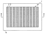
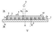
図1は、本発明に係る装飾体の第1の実施形態を示す平面図であり、図2は、図1に示されたII−II線に沿う断面図である。装飾体は、基材1と、複数の反射部2と、複数の透過部3とを含む。
1. First Embodiment FIG. 1 is a plan view showing a first embodiment of a decorative body according to the present invention, and FIG. 2 is a cross-sectional view taken along the line II-II shown in FIG. The decorative body includes a
基材1は、可視光透過性を有する無色のシート部材、またはパネル部材であり、装飾体の用途に応じて可撓性を備えるものであってもよい。基材1は、例えばポリカーボネイト、アクリル、ポリエステルなどの合成樹脂、あるいはガラスなどにより構成し得る。この基材1の厚みは、例えば0.1〜5.0mmである。
The
複数の反射部2と複数の透過部3は、基材1に設けられた発色領域10に形成されている。本実施形態において、発色領域10は、図示されるように矩形状に形成されているが、これに限定されることはなく、例えば、円形や三角形などの他の図形、複雑な図柄、あるいは文字形状などのデザイン性の高いものに形成してもよい。なお、基材1の大きさ、及び発色領域10の数や大きさは、用途に応じて適宜に決定される。
The plurality of
複数の反射部2は、基材1の一方の板面1bに、互いに間隙4をおいて線状に積層形成されている。一方、複数の透過部3は、図1に示されるように、基材1の板面1bを見たとき、複数の反射部2のなす間隙4と重なるように、基材1の板面1bに積層形成されている。言い換えれば、複数の透過部3の各々は、該間隙4を充填するように線状に形成されており、複数の透過部3と複数の反射部2は、図2に示されるように、板面1bにおいて、ストライプ模様をなすように、互いに隣接して交互に配置されている。もっとも、複数の透過部3と複数の反射部2の線がなす模様は、このようなストライプ模様に限定されるものではなく、例えば同心円状、波状、網状などの他の模様となし得る。
The plurality of reflecting
反射部2は、第1の色相を有するとともに、遮光性、及び可視光反射性を有している。反射部2は、汎用の有機顔料などの着色剤により第1の色相に着色されたものであって、例えば、不透明な反射色を有するインキを採用し得る。また、透過部3は、上記の第1の色相と異なる第2の色相を有するとともに、可視光透過性を有する。透過部3は、汎用の有機顔料などの着色剤により第2の色相に着色されたものであって、例えば、透明色を有するインキを採用し得る。複数の透過部3と複数の反射部2は、平板印刷、スクリーン印刷、凸版印刷、たこ印刷、デジタル印刷などの印刷手法、あるいは塗装手法によって、基材1の上に形成されている。
The
もっとも、反射部2と透過部3は、上述したような塗料に限定されず、例えば顔料などの着色剤により着色されたプラスチック基材であってもよい。この場合、反射部2と透過部3は、汎用の射出成形手段や接着手段を用いて形成される。
However, the
また、図1において、複数の透過部3と複数の反射部2の面積比は、1:9〜9:1の範囲であり、好ましくは4:6〜6:4である。複数の透過部3と複数の反射部2の幅寸法は、視認距離に応じて変動し、例えば視認距離が板面1bから25cmである場合、150〜500μmが好ましい。複数の透過部3と複数の反射部2の厚み寸法は、用途に応じて適宜に設定し得る。
Moreover, in FIG. 1, the area ratio of the some
このような装飾体によれば、次のような作用効果が得られる。すなわち、装飾体は、基材1が光透過性を有し、また、複数の反射部2がなす間隙4に可視光透過性を有する透過部3が重なっているから、基材1を挟んだ一方の側7Aに光源5がある場合、該間隙4を介して第2の色相の光5aが、基材の他方の側、すなわち視認側7Bに出射される。このとき、複数の反射部2は遮光性を有するから、該光源の光5bを遮断し、さらに、第2の色相の光5aによる、いわゆる逆光の効果のために第1の色相の光6は該視認側7Bにおいて視認され得ない。
According to such a decorative body, the following effects can be obtained. That is, in the decorative body, since the
また、基材1を挟んだ一方の側7Aに光源5がない場合、複数の反射部2は可視光反射性を有するから、基材1の視認側7Bから入射した光6が複数の反射部2により反射されて、第1の色相の光6が該視認側7Bにおいて視認される。このとき、該間隙4を介して第2の色相の光5aが視認側7Bに出射されることは実質的にないため、第2の色相の光5aは該視認側7Bにおいて視認され得ない。
In addition, when there is no
したがって、装飾体は、基材1を挟んだ一方の側7Aにおける光源5の有無に応じて、第1の色相、または第2の色相を選択的に発色することができる。
Therefore, the decorative body can selectively color the first hue or the second hue depending on the presence or absence of the
このような装飾体の典型的な適用例としては、携帯電話機などの電子機器の外装ケースがあり、この場合、上記の光源5として、この種の物品に備えられる液晶表示部のバックライトを使用することができる。この構成によれば、例えばメールや通話の着信時にバックライトが点灯したことを契機として、装飾体の発色領域10の色相を第1の色相から第2の色相に変化させることができる。もっとも、装飾体の適用例は、これに限られることはなく、健材、オーディオパネル、自動車などのメーターパネル、時計の文字盤なども含む。
As a typical application example of such a decorative body, there is an exterior case of an electronic device such as a mobile phone. In this case, a backlight of a liquid crystal display unit provided in this type of article is used as the
また、これまで基材1の色相、及び光源5が発する光の色相は無色であることを前提として説明してきたが、有色であってもよい。この場合、発色領域10の色相は、基材1の色相、及び/または光の色相と第1の色相、または第2の色相との混合色となる。なお、以下の実施形態についても、本実施形態と同様に、基材1の色相、及び光源5が発する光の色相は無色であるものとして説明する。
In the above description, the hue of the
2.第2の実施形態
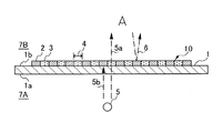
図3は、本発明に係る装飾体の第2の実施形態を示す平面図であり、図4は、図3に示されたIV−IV線に沿う断面図である。装飾体は、上述した実施形態と同様に、基材1と、複数の反射部2と、透過部3とを含み、個々の構成は同じであるが、透過部3の態様が異なっている。
2. Second Embodiment FIG. 3 is a plan view showing a second embodiment of a decorative body according to the present invention, and FIG. 4 is a cross-sectional view taken along line IV-IV shown in FIG. Similar to the above-described embodiment, the decorative body includes the
透過部3は、基材1において、複数の反射部2が設けられた板面1bの反対側の板面1aに積層されている。図1に示されるように、透過部3は、発色領域10の全体を含むように、基材1の板面1bを見たとき、複数の反射部2、及びそれらの間隙4と重なるように形成されている。
The
複数の反射部2は、基材1の一方の板面1bに、互いに間隙4をおいて線状に積層形成されている。該間隙4は、上述した実施形態とは異なり、空間である。
The plurality of reflecting
本実施形態の装飾体は、上述した実施形態と同様の作用効果を奏する。すなわち、透過部3が設けられた側7Aに光源5がある場合、透過部3、及び間隙4を通して第2の色相の光5aが視認側7Bに出射されて視認されるが、反射部2で反射された第1の色相の光6は視認されない。一方、光源5がない場合、視認側7Bにおいて、反射部2で反射された第1の色相の光6は視認されるが、第2の色相の光5aは視認側7Bに出射されない。
The decorative body of this embodiment has the same effects as the above-described embodiment. That is, when the
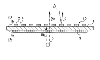
3.第3の実施形態
図5は、本発明に係る装飾体の第3の実施形態を示す断面図である。装飾体は、上述した実施形態と同様に、基材1と、複数の反射部2と、透過部3とを含み、個々の構成は同じであるが、反射部2と透過部3の態様が異なっている。
3. Third Embodiment FIG. 5 is a cross-sectional view showing a third embodiment of the decorative body according to the present invention. Similarly to the above-described embodiment, the decorative body includes the
すなわち、透過部3は、基材1の視認側7Bの板面1aに積層形成されており、この透過部3の表面に、複数の反射部2が間隙4をおいて積層形成されている。したがって、第2の実施形態と同様に、透過部3は、基材1の板面1aを見たとき、複数の反射部2、及びそれらの間隙4と重なるように形成されている。
That is, the
本実施形態の装飾体は、上述した実施形態と同様の作用効果を奏する。すなわち、基材1の一方の側7Aに光源5がある場合、透過部3、及び間隙4を通して第2の色相の光5aが視認側7Bに出射されて視認されるが、反射部2で反射された第1の色相の光6は視認されない。一方、光源5がない場合、視認側7Bにおいて、反射部2で反射された第1の色相の光6は視認されるが、第2の色相の光5aは視認側7Bに出射されない。
The decorative body of this embodiment has the same effects as the above-described embodiment. That is, when the
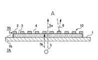
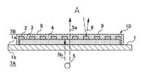
4.第4の実施形態
図6は、本発明に係る装飾体の第4の実施形態を示す断面図である。装飾体は、上述した実施形態と同様に、基材1と、複数の反射部2と、透過部3とを含み、個々の構成は同じであるが、反射部2と透過部3の態様が異なっている。
4). 4th Embodiment FIG. 6: is sectional drawing which shows 4th Embodiment of the decoration body which concerns on this invention. Similarly to the above-described embodiment, the decorative body includes the
すなわち、複数の反射部2は、基板1の一方の板面1aに間隙4をおいて積層形成され、透過部3は、複数の反射部2を覆って該間隙4を充填するように、基材1の板面1aに積層形成されている。したがって、第2の実施形態と同様に、透過部3は、基材1の板面1aを見たとき、複数の反射部2、及びそれらの間隙4と重なるように形成されている。なお、本実施形態では、これまでの実施形態とは異なり、視認側7Bは、基板1の他方の板面1bが面する側にある。
That is, the plurality of reflecting
本実施形態の装飾体は、上述した実施形態と同様の作用効果を奏する。すなわち、複数の反射部2と透過部3とが設けられた側7Aに光源5がある場合、透過部3、及び間隙4を通して第2の色相の光5aが視認側7Bに出射されて視認されるが、反射部2で反射された第1の色相の光6は視認されない。一方、光源5がない場合、視認側7Bにおいて、反射部2で反射された第1の色相の光6は視認されるが、第2の色相の光5aは視認側7Bに出射されない。
The decorative body of this embodiment has the same effects as the above-described embodiment. That is, when the
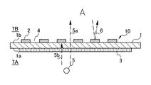
5.第5の実施形態
図7は、本発明に係る装飾体の第5の実施形態を示す断面図である。装飾体は、上述した実施形態と同様に、基材1と、複数の反射部2と、透過部3とを含み、反射部2を除き、個々の構成は同じである。
5. Fifth Embodiment FIG. 7 is a cross-sectional view showing a fifth embodiment of a decorative body according to the present invention. Similarly to the above-described embodiment, the decorative body includes the
これまでの実施形態では、反射部2が単一層により構成されているのに対し、本実施形態では、反射部2は、透明な第1層2bと、第1層2bに積層された不透明な第2層2aとを含んでいる。第1層2bは、第1の色相を有し、第2層2aは、遮光性、及び可視光反射性を有する。第1層2bとしては、例えば、可視光透過性、すなわち透明色を有するインキを採用し得る。第2層2aとしては、不透明白色のインキを採用し得る。もっとも、第1層2bと第2層2aは、上述したような塗料に限定されず、例えば顔料などの着色剤により着色されたプラスチック基材であってもよい。
In the embodiments so far, the reflecting
本実施形態の装飾体は、全体的構成は第4の実施形態と同じであるから、図示されるように、これと同様の作用効果を奏する。 Since the overall configuration of the decorative body of the present embodiment is the same as that of the fourth embodiment, the same effects as those shown in FIG.
6.第6の実施形態
図8は、本発明に係る装飾体の第6の実施形態を示す断面図である。装飾体は、上述した実施形態と同様に、基材1と、複数の反射部2と、透過部3とを含み、個々の構成は同じである。本実施形態の相違点は、装飾体がさらに複数の突起8を含む点にある。
6). Sixth Embodiment FIG. 8 is a cross-sectional view showing a sixth embodiment of a decorative body according to the present invention. Similarly to the above-described embodiment, the decorative body includes the
複数の突起8は、それぞれ、可視光透過性を有し、基材の板面1a,1bを見たとき、複数の反射部2の各々と重なるように基材1の視認側7Bの板面1bに形成されている。この突起8の形成には、平板印刷、スクリーン印刷、凸版印刷、たこ印刷、デジタル印刷などの印刷手法を用いることができる。なお、突起8は、必ずしも全ての反射部2と重なるように設ける必要はなく、その一部のみと重なるように設けてもよい。
Each of the plurality of protrusions 8 has visible light permeability, and the plate surface on the
本実施形態の装飾体は、全体的構成は第4の実施形態と同じであるから、図示されるように、これと同様の作用効果を奏するが、これに加えて、複数の突起8による作用効果を奏する。すなわち、複数の突起8は、光の屈折作用によって、視認側7Bの板面1bから所定距離だけ離れた位置に、見る方向によって模様が移動する立体的な像(いわゆる、ゆらぎ)を作り出すのである。
Since the overall configuration of the decorative body of this embodiment is the same as that of the fourth embodiment, as shown in the figure, the same effect is obtained, but in addition, the action of the plurality of protrusions 8 is achieved. There is an effect. In other words, the plurality of protrusions 8 create a three-dimensional image (so-called fluctuation) in which the pattern moves depending on the viewing direction at a position away from the
なお、複数の突起8は、図8とは異なり、透過部3の表面に形成してもよい。
Note that the plurality of protrusions 8 may be formed on the surface of the
7.第7の実施形態
図9は、本発明に係る装飾体の第7の実施形態を示す断面図である。装飾体は、上述した実施形態と同様に、基材1と、複数の反射部2と、透過部3とを含み、個々の構成は同じである。本実施形態の装飾体は、図5に示された構成に、さらに可視光透過性の保護膜9を設けたものである。
7). 7th Embodiment FIG. 9: is sectional drawing which shows 7th Embodiment of the decoration body which concerns on this invention. Similarly to the above-described embodiment, the decorative body includes the
保護膜9は、一液ニス、反応性二液ニス、UVニス、あるいは無色の透明フィルムなどにより構成され、複数の反射部2と透過部3とを覆うように発色領域10に形成されている。この保護膜9の形成には、周知の塗布手段、あるいは貼着手段を用いることができる。なお、保護膜9は、必ずしも発色領域10の全体を覆うように設ける必要はなく、その一部のみを覆うように設けてもよい。
The protective film 9 is composed of a one-part varnish, a reactive two-part varnish, a UV varnish, a colorless transparent film, or the like, and is formed in the
本実施形態の装飾体は、全体的構成は第3の実施形態と同じであるから、図示されるように、これと同様の作用効果を奏するが、これに加えて、保護膜9による作用効果を奏する。すなわち、保護膜9は、複数の反射部2と透過部3とを保護し、その劣化を妨げる。なお、保護膜9は、これまで述べた全ての実施形態、及び後述する実施形態にも適用することができる。
Since the overall configuration of the decorative body of the present embodiment is the same as that of the third embodiment, as shown in the figure, the same effect is obtained, but in addition, the effect of the protective film 9 is achieved. Play. That is, the protective film 9 protects the plurality of
8.第8の実施形態
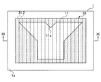
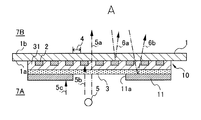
図10は、本発明に係る装飾体の第8の実施形態を示す平面図であり、図11は、図10に示されたXI−XI線に沿う断面図である。本実施形態の装飾体は、光源5がある場合に模式化した文字「Y」が発色領域10に表示されるように構成したものである。
8). Eighth Embodiment FIG. 10 is a plan view showing an eighth embodiment of a decorative body according to the present invention, and FIG. 11 is a cross-sectional view taken along the line XI-XI shown in FIG. The decorative body of the present embodiment is configured such that the character “Y” schematically displayed in the case where the
装飾体は、基材1と、複数の反射部2と、透過部3と、色相調整部31と、遮光部11とを含む。
The decorative body includes a
複数の反射部2は、基材1の一方の板面1aに、互いに間隙4をおいて積層形成されており、色相調整部31は、基材1の一方の板面1aに、複数の反射部2を覆うように積層形成されている。色相調整部31は、スモーク色などの比較的に暗い色相を有し、例えば可視光透過性インキで構成される。
The plurality of reflecting
また、透過部3は、色相調整部31の表面に積層形成され、遮光部11は、この透過部3の表面に積層形成され、基材1の表面1aを見たときに、模式化した文字「Y」を構成するように中抜き部分11aを有している。遮光部11は、例えばグレーなどの比較的に暗い色相を有し、例えば遮光性インキで構成される。もっとも、色相調整部31と遮光部11は、このような塗料に限定されず、例えば顔料などの着色剤により着色されたプラスチック基材であってもよい。
The
本実施形態の装飾体は、上述した実施形態と同様の作用効果を奏することにより、光源5がある場合に模式化した文字「Y」が発色領域10に表示され、光源5がない場合、文字が消えて反射部2の第1の色相が矩形状に発色領域10に表示される。
The decorative body of the present embodiment has the same effect as the above-described embodiment, so that the character “Y” schematically displayed when the
すなわち、透過部3などが設けられた側7Aに光源5がある場合、遮光部11の中抜き部分11a、透過部3、色相調整部31、間隙4、及び基材1を通して第2の色相の光5aが視認側7Bに出射される。このとき、複数の反射部2は遮光性を有するから、光源5の光5bを遮断し、遮光部11も遮光性を有するから、光源5の光5cを遮断する。また、第2の色相の光5aによる、いわゆる逆光の効果のために第1の色相の光6aは視認側7Bにおいて視認され得ない。
That is, when the
また、基材1を挟んだ一方の側7Aに光源5がない場合、複数の反射部2は可視光反射性を有するから、基材1の視認側7Bから入射した光が複数の反射部2により反射されて、第1の色相の光6aが視認側7Bにおいて視認される。このとき、複数の反射部2がなす間隙4を介して第2の色相の光5aが視認側7Bに出射されることは実質的にないため、第2の色相の光5aは視認側7Bにおいて視認され得ない。
Further, when there is no
したがって、本発明に係る装飾体は、基材1を挟んだ一方の側7Aにおける光源5の有無に応じて、第1の色相を有する矩形状、または第2の色相を有する文字「Y」を選択的に発色表示することができる。
Therefore, the decorative body according to the present invention has a rectangular shape having the first hue or the letter “Y” having the second hue depending on the presence or absence of the
本実施形態において、色相調整部31は、必須の構成ではないが、透過部3が赤などの比較的に明るい色相を有している場合に、透過部3の色相が間隙4から視認側7Bへ漏れることを妨げている。つまり、色相調整部31は、その暗い色相によって、視認側7Bから入射して遮光部11により反射された光6bの輝度を低下させているのである。これにより、光源5の有無に関わらず、透過部3の色相を有する光6bが、図10における遮光部11の中抜き部分11aの外側から出射されることはない。なお、光源5がある場合に、遮光部11の中抜き部分11aを透過する光5aは、輝度が高いために、実質的に色相調整部31による影響を受けることは無い。
In the present embodiment, the
9.第9の実施形態
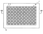
図12は、本発明に係る装飾体の第9の実施形態を示す平面図であり、図13は、図12に示されたXIII−XIII線に沿う断面図である。装飾体は、上述した実施形態と同様に、基材1と、複数の反射部2と、複数の透過部3とを含み、個々の構成は同じであるが、反射部2の態様が異なっている。
9. Ninth Embodiment FIG. 12 is a plan view showing a ninth embodiment of a decorative body according to the present invention, and FIG. 13 is a cross-sectional view taken along line XIII-XIII shown in FIG. Similarly to the above-described embodiment, the decorative body includes the
すなわち、これまで述べた実施形態における反射部2は平面視で線状に形成されていたのに対して、本実施形態における反射部2は、透過部3とともに矩形状に形成されている。具体的には、複数の反射部2と複数の透過部3は、基材1の一方の板面1bに積層され、市松模様をなすように、交互に隣接して形成されている。言い換えれば、複数の透過部3の各々は、複数の反射部2がなす矩形状の間隙4を充填するように形成されており、これまで述べた実施形態と同様に、基材1の板面1bを見たとき、複数の反射部2がなす間隙4と重なっている。
That is, the
本実施形態の装飾体は、上述した実施形態と同様の作用効果を奏する。すなわち、基材1の一方の側7Aに光源5がある場合、透過部3を通して第2の色相の光5aが視認側7Bに出射されて視認されるが、反射部2で反射された第1の色相の光6は視認されない。一方、光源5がない場合、視認側7Bにおいて、反射部2で反射された第1の色相の光6は視認されるが、第2の色相の光5aは視認側7Bに出射されない。
The decorative body of this embodiment has the same effects as the above-described embodiment. That is, when the
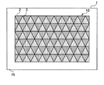
また、図14に示されるように、複数の反射部2と複数の透過部3を平面視で三角形状とし、交互に隣接するように基材1の板面1bに規則的に積層形成しても、同様の作用効果を奏することは言うまでもない。つまり、複数の反射部2と複数の透過部3のなす形状は、限定されないのである。
Further, as shown in FIG. 14, the plurality of
10.第10の実施形態
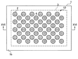
図15は、本発明に係る装飾体の第10の実施形態を示す平面図であり、図16は、図15に示されたXVI−XVI線に沿う断面図である。装飾体は、上述した実施形態と同様に、基材1と、複数の反射部2と、透過部3とを含み、個々の構成は同じであるが、反射部2と透過部3の態様が異なっている。
10. Tenth Embodiment FIG. 15 is a plan view showing a tenth embodiment of a decorative body according to the present invention, and FIG. 16 is a cross-sectional view taken along the line XVI-XVI shown in FIG. Similarly to the above-described embodiment, the decorative body includes the
すなわち、複数の反射部2は、平面視で円形状をなし、基材1の一方の板面1bに、互いに間隙4をおいて規則的に積層形成されている。この間隙4は、これまでの実施形態とは異なり、平面視で反射部2の周囲全体を取り囲む空間となっている。また、透過部3は、該板面1bの反対側の板面1aに積層されている。図15に示されるように、透過部3は、発色領域10の全体を含むように、基材1の板面1bを見たとき、複数の反射部2、及びそれらの間隙4と重なるように形成されている。
That is, the plurality of reflecting
本実施形態の装飾体は、上述した実施形態と同様の作用効果を奏する。すなわち、基材1の一方の側7Aに光源5がある場合、透過部3と間隙4とを通して第2の色相の光5aが視認側7Bに出射されて視認されるが、反射部2で反射された第1の色相の光6は視認されない。一方、光源5がない場合、視認側7Bにおいて、反射部2で反射された第1の色相の光6は視認されるが、第2の色相の光5aは視認側7Bに出射されない。
The decorative body of this embodiment has the same effects as the above-described embodiment. That is, when the
このように、反射部2と透過部3は、如何なる形状であっても、その積層形態は限定されず、図2、及び図3、さらには図5〜図8に示された何れの形態も採り得る。
As described above, the
なお、これまで述べた実施形態において、反射部2としてミラーインキを使用すると、光源5がない場合に、発色領域10があたかも鏡面のようになり、デザイン性を高めることができる。
In the embodiment described so far, when mirror ink is used as the
以上、好ましい実施例を参照して本発明の内容を具体的に説明したが、本発明の基本的技術思想及び教示に基づいて、当業者であれば、種々の変形態様を採り得ることは自明である。 Although the contents of the present invention have been specifically described above with reference to the preferred embodiments, it is obvious that those skilled in the art can take various modifications based on the basic technical idea and teachings of the present invention. It is.
1 基材
1a,1b 板面
2 反射部
2a,2b 第1層、第2層
3 透過部
4 間隙
8 突起
DESCRIPTION OF
Claims (6)
前記基材は、可視光透過性を有するシート部材、またはパネル部材であり、
前記複数の反射部は、第1の色相を有するとともに、遮光性、及び可視光反射性を有し、前記基材に互いに間隙をおいて形成されており、
前記1以上の透過部は、前記第1の色相と異なる第2の色相を有するとともに、可視光透過性を有し、前記基材の板面を見たとき、少なくとも部分的に前記間隙と重なるように、前記基材に形成されている、
装飾体。 A decorative body including a base material, a plurality of reflection portions, and one or more transmission portions,
The base material is a sheet member having visible light permeability, or a panel member,
The plurality of reflecting portions have a first hue, a light shielding property, and a visible light reflecting property, and are formed with a gap from each other on the base material.
The one or more transmissive portions have a second hue different from the first hue and have a visible light permeability, and at least partially overlap the gap when the plate surface of the substrate is viewed. As formed on the substrate,
Decorative body.
前記複数の反射部と前記1以上の透過部は、前記基材の一方の板面に積層され、
前記1以上の透過部の各々は、前記間隙を充填するように形成されている、
装飾体。 The decorative body according to claim 1,
The plurality of reflection portions and the one or more transmission portions are stacked on one plate surface of the base material,
Each of the one or more transmission parts is formed so as to fill the gap.
Decorative body.
前記複数の反射部は、前記基材の一方の板面に積層され、
前記1以上の透過部は、前記基材の他方の板面に積層された、
装飾体。 The decorative body according to claim 1,
The plurality of reflecting portions are laminated on one plate surface of the base material,
The one or more transmission parts are stacked on the other plate surface of the base material,
Decorative body.
前記1以上の透過部の1つは、前記基材の板面を見たとき、前記複数の反射部、及び前記間隙と重なるように形成されている、
装飾体。 A decorative body according to any one of claims 1 to 3,
One of the one or more transmission parts is formed so as to overlap the plurality of reflection parts and the gap when the plate surface of the base material is viewed.
Decorative body.
前記複数の反射部は、第1層と、前記第1層に積層された第2層とを含んでおり、
前記第1層は、前記第1の色相を有しており、
前記第2層は、遮光性、及び可視光反射性を有する、
装飾体。 A decorative body according to any one of claims 1 to 4,
The plurality of reflective portions include a first layer and a second layer stacked on the first layer,
The first layer has the first hue;
The second layer has a light blocking property and a visible light reflecting property.
Decorative body.
さらに複数の突起を含み、
前記複数の突起は、それぞれ、可視光透過性を有し、前記基材の板面を見たとき、前記複数の反射部の各々と重なるように前記基材に形成されている、
装飾体。 A decorative body according to any one of claims 1 to 5,
A plurality of protrusions,
Each of the plurality of protrusions has visible light permeability and is formed on the base material so as to overlap each of the plurality of reflection portions when the plate surface of the base material is viewed.
Decorative body.
Priority Applications (1)
| Application Number | Priority Date | Filing Date | Title |
|---|---|---|---|
| JP2011024552A JP2012162005A (en) | 2011-02-08 | 2011-02-08 | Decorative body |
Applications Claiming Priority (1)
| Application Number | Priority Date | Filing Date | Title |
|---|---|---|---|
| JP2011024552A JP2012162005A (en) | 2011-02-08 | 2011-02-08 | Decorative body |
Publications (1)
| Publication Number | Publication Date |
|---|---|
| JP2012162005A true JP2012162005A (en) | 2012-08-30 |
Family
ID=46841908
Family Applications (1)
| Application Number | Title | Priority Date | Filing Date |
|---|---|---|---|
| JP2011024552A Pending JP2012162005A (en) | 2011-02-08 | 2011-02-08 | Decorative body |
Country Status (1)
| Country | Link |
|---|---|
| JP (1) | JP2012162005A (en) |
Cited By (1)
| Publication number | Priority date | Publication date | Assignee | Title |
|---|---|---|---|---|
| JP2016221030A (en) * | 2015-06-01 | 2016-12-28 | 紀伊産業株式会社 | Decorative molded product and production method thereof |
Citations (3)
| Publication number | Priority date | Publication date | Assignee | Title |
|---|---|---|---|---|
| JPS6228600U (en) * | 1985-08-02 | 1987-02-20 | ||
| JP2001180198A (en) * | 1999-10-14 | 2001-07-03 | Takasago Electric Ind Co Ltd | Decorative display |
| JP2005169879A (en) * | 2003-12-12 | 2005-06-30 | Nakai Meihan Kk | Three-dimensional pattern decorative body |
-
2011
- 2011-02-08 JP JP2011024552A patent/JP2012162005A/en active Pending
Patent Citations (3)
| Publication number | Priority date | Publication date | Assignee | Title |
|---|---|---|---|---|
| JPS6228600U (en) * | 1985-08-02 | 1987-02-20 | ||
| JP2001180198A (en) * | 1999-10-14 | 2001-07-03 | Takasago Electric Ind Co Ltd | Decorative display |
| JP2005169879A (en) * | 2003-12-12 | 2005-06-30 | Nakai Meihan Kk | Three-dimensional pattern decorative body |
Cited By (1)
| Publication number | Priority date | Publication date | Assignee | Title |
|---|---|---|---|---|
| JP2016221030A (en) * | 2015-06-01 | 2016-12-28 | 紀伊産業株式会社 | Decorative molded product and production method thereof |
Similar Documents
| Publication | Publication Date | Title |
|---|---|---|
| CN100456100C (en) | Display device and manufacturing method thereof | |
| US10048538B1 (en) | Display device | |
| CN109551828B (en) | Optical decoration | |
| JP2012215621A (en) | Liquid crystal display device | |
| CN207274250U (en) | Decorative optical part | |
| JP2010201652A (en) | Decorative body and method for manufacturing the same | |
| JP2008185767A (en) | Optical film and manufacturing method thereof | |
| JP2008018631A (en) | Brilliantly shining decorative body and its manufacturing method | |
| JP7240619B2 (en) | Display devices with panels, interior and exterior materials, moving bodies and panels | |
| JP4690794B2 (en) | Multiple reflection panel | |
| JP2012212006A (en) | Information display panel and transportation device including information display panel | |
| JP5609138B2 (en) | LAMINATED SHEET FOR INFORMATION DISPLAY PANEL, INFORMATION DISPLAY PANEL, AND TRANSPORTATION EQUIPMENT HAVING THE INFORMATION DISPLAY PANEL | |
| WO2021162113A1 (en) | Decorative sheet, display device with decorative sheet, and article with decorative sheet | |
| JP3430951B2 (en) | Display device and electronic clock | |
| JP3970250B2 (en) | 3D printed material and 3D printing method | |
| JP2012162005A (en) | Decorative body | |
| WO2011013762A1 (en) | Information display panel and transport machine equipped with information display panel | |
| JP4997689B2 (en) | Display device and electronic device | |
| JP4748284B2 (en) | Information display panel and transportation equipment equipped with the information display panel | |
| JP5600998B2 (en) | Laminated sheet for information display panel, information display panel, and information display device | |
| JP3979076B2 (en) | Electronics | |
| CN107340628A (en) | A kind of display base plate and display device | |
| CN207181733U (en) | Optical thin film and its shell with the optical thin film | |
| WO2020115963A1 (en) | Display device | |
| JP7632174B2 (en) | Low-reflection member, display device with low-reflection member |
Legal Events
| Date | Code | Title | Description |
|---|---|---|---|
| A621 | Written request for application examination |
Free format text: JAPANESE INTERMEDIATE CODE: A621 Effective date: 20121019 |
|
| A871 | Explanation of circumstances concerning accelerated examination |
Free format text: JAPANESE INTERMEDIATE CODE: A871 Effective date: 20121019 |
|
| A02 | Decision of refusal |
Free format text: JAPANESE INTERMEDIATE CODE: A02 Effective date: 20130522 |