JP2012162012A - Liquid injection device - Google Patents
Liquid injection device Download PDFInfo
- Publication number
- JP2012162012A JP2012162012A JP2011024683A JP2011024683A JP2012162012A JP 2012162012 A JP2012162012 A JP 2012162012A JP 2011024683 A JP2011024683 A JP 2011024683A JP 2011024683 A JP2011024683 A JP 2011024683A JP 2012162012 A JP2012162012 A JP 2012162012A
- Authority
- JP
- Japan
- Prior art keywords
- liquid
- ejected
- ink
- ejection
- medium
- Prior art date
- Legal status (The legal status is an assumption and is not a legal conclusion. Google has not performed a legal analysis and makes no representation as to the accuracy of the status listed.)
- Granted
Links
Images
Landscapes
- Ink Jet (AREA)
- Particle Formation And Scattering Control In Inkjet Printers (AREA)
Abstract
【課題】噴射ヘッドを移動させることなくフラッシング動作を行うことが可能であり、且
つフラッシングによって噴射した液体を確実に回収可能な技術を提供する。
【解決手段】噴射ヘッドと被噴射媒体との間に発生させた電位差によって噴射ヘッドから
噴射された液体(帯電した液体)の速度を減速させた上で、減速した液体を液体吸引手段
によって吸引する。こうすれば、フラッシング動作によって噴射した液体を回収できるの
で、被噴射媒体に液体が付着して汚れる心配がない。また、フラッシング動作によって噴
射した液体は回収できるので、フラッシング動作のために噴射ヘッドを別の位置に移動さ
せる必要がない。その結果、噴射ヘッドの移動に伴う位置ずれが起こることがないので、
同じ位置にインクを噴射することが可能である。
【選択図】図4A technique capable of performing a flushing operation without moving an ejection head and capable of reliably collecting a liquid ejected by flushing.
The speed of a liquid (charged liquid) ejected from the ejection head is reduced by the potential difference generated between the ejection head and the ejection target medium, and the reduced liquid is sucked by the liquid suction means. . By doing so, the liquid ejected by the flushing operation can be collected, so there is no fear that the liquid adheres to the ejected medium and becomes dirty. Further, since the liquid ejected by the flushing operation can be collected, it is not necessary to move the ejection head to another position for the flushing operation. As a result, there is no misalignment that accompanies the movement of the ejection head,
It is possible to eject ink at the same position.
[Selection] Figure 4
Description
本発明は、インクなどの液体を噴射する液体噴射装置に関する。 The present invention relates to a liquid ejecting apparatus that ejects a liquid such as ink.
いわゆるインクジェットプリンターでは、印刷媒体上にインクを噴射することで画像を
印刷する。インクを噴射する位置や噴射量は極めて精度良く制御することが可能であるた
め、高画質な画像を印刷することができる。また、この技術を利用して各種の機能材料を
含んだ液体を基板上に噴射することにより、電極やセンサーなどの各種機能部品を形成す
ることも提案されている。
A so-called inkjet printer prints an image by ejecting ink onto a print medium. Since the position and amount of ink ejected can be controlled with extremely high accuracy, a high-quality image can be printed. It has also been proposed to form various functional parts such as electrodes and sensors by ejecting liquids containing various functional materials onto a substrate using this technique.
こうした液体噴射装置では、被噴射媒体(印刷媒体)上で噴射ヘッドを往復動(主走査
)させながら、被噴射媒体(印刷媒体)の位置を少しずつ移動(副走査)させることによ
って液体を噴射することが一般的であるが、その一方で、噴射ヘッドは移動させずに被噴
射媒体(印刷媒体)だけを少しずつ移動(副走査)させて液体を噴射する方法も提案され
ている。尚、本明細書中では、前者の噴射方式を「シリアル噴射方式」と呼び、後者の噴
射方式を「ライン噴射方式」と呼ぶこととする。
In such a liquid ejecting apparatus, the liquid is ejected by moving the position of the ejection target medium (printing medium) little by little (sub-scanning) while reciprocating (main scanning) the ejection head on the ejection target medium (printing medium). On the other hand, there is also proposed a method of ejecting liquid by moving (sub-scanning) only the ejected medium (print medium) little by little without moving the ejecting head. In the present specification, the former injection method is called “serial injection method”, and the latter injection method is called “line injection method”.
何れの噴射方式を採用した場合でも、噴射ノズル内の液体が徐々に増粘するので、定期
的に液体の噴射(フラッシング)を行うことにより、噴射ノズル内で増粘した液体を除去
する必要がある。噴射ヘッドを主走査させるシリアル噴射方式では、被噴射媒体が搬送さ
れる領域外にキャップ部材を設けておき、噴射ヘッドをここまで移動させてキャップ部材
に向かって液体を噴射することで増粘した液体を除去する。一方、ライン噴射方式の液体
噴射装置では、シリアル噴射方式と同様な方法でフラッシングを実行しようとすると、噴
射ヘッドをキャップ部材の位置から元の位置に戻す際に位置ずれが生ずることで、同じ位
置に液体を噴射することができなくなる場合がある。
Regardless of which injection method is used, the liquid in the injection nozzle gradually increases in viscosity, so it is necessary to remove the liquid that has increased in viscosity in the injection nozzle by periodically performing liquid flushing. is there. In the serial ejection method in which the ejection head is main-scanned, a cap member is provided outside the area where the ejection medium is conveyed, and the viscosity is increased by moving the ejection head so far and ejecting liquid toward the cap member. Remove liquid. On the other hand, in the liquid ejecting apparatus of the line ejecting method, if the flushing is executed by the same method as the serial ejecting method, a positional deviation occurs when the ejecting head is returned from the position of the cap member to the original position. In some cases, it becomes impossible to eject the liquid.
そこで、噴射ヘッドの隣に吸引手段を設けておき(特許文献1)、フラッシングによっ
て噴射した液体を吸引手段で吸い込むことで、噴射ヘッドを移動させずにフラッシングを
実行することが考えられる。
Therefore, it is conceivable to perform flushing without moving the ejection head by providing a suction means next to the ejection head (Patent Document 1) and sucking the liquid ejected by flushing with the suction means.
しかし、フラッシング中は液体が高速で噴射されるので、噴射した液体を吸引によって
確実に回収することは困難であるという問題があった。その結果、例えば噴射した液体が
被噴射媒体に付着して、被噴射媒体を汚してしまうことあるという問題があった。
However, since the liquid is ejected at high speed during the flushing, there is a problem that it is difficult to reliably collect the ejected liquid by suction. As a result, there has been a problem that, for example, the ejected liquid may adhere to the ejection medium and contaminate the ejection medium.
この発明は、従来の技術が有する上述した課題の少なくとも一部を解決するためになさ
れたものであり、噴射ヘッドを移動させることなくフラッシングを行うことが可能であり
、且つフラッシングによって噴射した液体を確実に回収する技術の提供を目的とする。
The present invention has been made in order to solve at least a part of the above-described problems of the prior art, and it is possible to perform flushing without moving the ejection head, and the liquid ejected by flushing can be used. The purpose is to provide technology for reliable collection.
上述した課題の少なくとも一部を解決するために、本発明の液体噴射装置は次の構成を
採用した。すなわち、
噴射ヘッドから被噴射媒体に向けて液体を噴射する液体噴射装置であって、
前記噴射ヘッドから噴射される前記液体を帯電させる液体帯電手段と、
前記噴射ヘッドから帯電された状態で噴射された前記液体が減速する方向の電位差を、
該噴射ヘッドと前記被噴射媒体との間に発生させる電位差発生手段と、
前記噴射ヘッドと前記被噴射媒体との間に存在する前記液体を吸引する液体吸引手段と
を備えることを要旨とする。
In order to solve at least a part of the problems described above, the liquid ejecting apparatus of the present invention employs the following configuration. That is,
A liquid ejecting apparatus that ejects liquid from an ejecting head toward an ejected medium,
Liquid charging means for charging the liquid ejected from the ejection head;
A potential difference in a direction in which the liquid ejected while being charged from the ejection head decelerates,
A potential difference generating means for generating between the ejection head and the ejection medium;
And a liquid suction means for sucking the liquid existing between the ejection head and the ejection target medium.
このような本発明の液体噴射装置においては、噴射ヘッドと被噴射媒体との間に発生さ
せた電位差によって噴射ヘッドから噴射された液体(帯電した液体)の速度を減速させた
上で、減速した液体を液体吸引手段によって吸引する。尚、液体を帯電させる場合には、
例えば液体を帯電させるための装置を用いて帯電させてもよいし、液体が通路を移動する
間に生ずる静電気によって帯電させてもよい。また、噴射ヘッドと被噴射媒体との間に電
位差を発生させる場合には、被噴射媒体側に液体と同じ極性の電圧を印加することで電位
差を発生させてもよいし、噴射ヘッド側に液体と逆極性の電圧を印加することで電位差を
発生させてもよい。
In such a liquid ejecting apparatus of the present invention, the speed of the liquid (charged liquid) ejected from the ejecting head is reduced by the potential difference generated between the ejecting head and the ejection target medium and then decelerated. Liquid is sucked by the liquid suction means. When charging the liquid,
For example, it may be charged using a device for charging the liquid, or may be charged by static electricity generated while the liquid moves through the passage. In addition, when a potential difference is generated between the ejection head and the ejection medium, the potential difference may be generated by applying a voltage having the same polarity as the liquid to the ejection medium side, or the liquid is generated on the ejection head side. A potential difference may be generated by applying a voltage having the opposite polarity.
こうすれば、フラッシング動作によって噴射された液体の速度を減速させることにより
、液体に対して液体吸引手段の吸引力を十分に作用させることができるので、噴射された
液体を回収することができる。従って、フラッシング動作時に噴射された液体によって被
噴射媒体が汚れてしまうことを回避することが可能である。また、このようにフラッシン
グ動作によって噴射された液体を回収可能とすれば、噴射ヘッドは元の位置(液体を噴射
する位置)から別の位置に移動させる必要がない。その結果、噴射ヘッドの移動に伴って
噴射ヘッドの位置ずれが生ずることを防ぐことができるので、フラッシング動作の前後で
同じ位置に液体を噴射することが可能となる。
In this way, by reducing the speed of the liquid ejected by the flushing operation, the suction force of the liquid suction means can sufficiently act on the liquid, so that the ejected liquid can be collected. Therefore, it is possible to avoid the ejection target medium from being contaminated by the liquid ejected during the flushing operation. Further, if the liquid ejected by the flushing operation can be collected in this manner, the ejection head does not need to be moved from the original position (position for ejecting the liquid) to another position. As a result, it is possible to prevent the displacement of the ejection head as the ejection head moves, so that it is possible to eject liquid to the same position before and after the flushing operation.
また、上述した本発明の液体噴射装置においては、噴射ヘッドに対して背面側から被噴
射媒体を支える媒体支持部と噴射ヘッドとの間に、噴射された液体の速度を減速させる方
向の電位差を発生させることとしてもよい。
Further, in the above-described liquid ejecting apparatus of the present invention, a potential difference in the direction of decelerating the speed of the ejected liquid is provided between the ejecting head and the medium support unit that supports the ejected medium from the back side with respect to the ejecting head. It may be generated.
噴射ヘッドと媒体支持部とは互いに対向する位置に設けられる。従って、噴射ヘッドと
媒体支持部との間に液体の速度を減速させる方向の電位差を発生させることとすれば、こ
のような電位差を容易に発生させることが可能となる。
The ejection head and the medium support portion are provided at positions facing each other. Therefore, if a potential difference is generated between the ejection head and the medium support portion in the direction in which the liquid speed is reduced, such a potential difference can be easily generated.
また、上述した本発明の液体噴射装置の液体吸引手段は、噴射ヘッドから噴射された液
体を被噴射媒体が搬送される方向から吸引することとしてもよい。
Further, the liquid suction unit of the liquid ejecting apparatus of the present invention described above may suck the liquid ejected from the ejecting head from the direction in which the ejected medium is conveyed.
被噴射媒体を搬送すると搬送方向に向かって気流が生ずるため、被噴射媒体を搬送しな
がらフラッシング動作を行った場合には、噴射ヘッドから噴射した液体が気流によって搬
送方向に移動する。従って、被噴射媒体が搬送される方向から液体を吸引することとすれ
ば、フラッシング動作によって噴射された液体を効率よく回収することが可能となる。
When the ejected medium is transported, an air flow is generated in the transport direction. Therefore, when a flushing operation is performed while transporting the ejected medium, the liquid ejected from the ejecting head moves in the transport direction by the air stream. Therefore, if the liquid is sucked from the direction in which the ejection target medium is conveyed, the liquid ejected by the flushing operation can be efficiently collected.
また、上述した本発明の液体噴射装置は、電位差発生手段によって電位差を発生させな
がら液体を噴射する第1動作状態と、電位差を発生させることなく液体を噴射する第2動
作状態とを切り換える切換制御手段を備えることとしてもよい。
The above-described liquid ejecting apparatus of the present invention is a switching control that switches between a first operating state in which liquid is ejected while generating a potential difference by the potential difference generating means and a second operating state in which liquid is ejected without generating a potential difference. Means may be provided.
このような切換制御手段を設けておけば、フラッシング動作を行う状態(すなわち第1
動作状態)と、被噴射媒体への液体の噴射を行う状態(すなわち第2動作状態)との切り
換えを迅速に行うことができる。従って、フラッシング動作後に被噴射媒体への液体の噴
射を迅速に再開することが可能となる。
If such a switching control means is provided, the state in which the flushing operation is performed (that is, the first operation is performed).
It is possible to quickly switch between the operation state) and the state in which the liquid is ejected onto the ejection target medium (that is, the second operation state). Accordingly, it is possible to quickly restart the ejection of the liquid onto the ejection target medium after the flushing operation.
以下では、上述した本願発明の内容を明確にするために、次のような順序に従って実施
例を説明する。
A.装置構成:
B.本実施例のインクの回収機構:
C.変形例:
C−1.第1変形例:
C−2.第2変形例:
C−3.第3変形例:
C−4.第4変形例:
Hereinafter, in order to clarify the contents of the present invention described above, examples will be described in the following order.
A. Device configuration:
B. Ink recovery mechanism of this embodiment:
C. Variations:
C-1. First modification:
C-2. Second modification:
C-3. Third modification:
C-4. Fourth modification:
A.装置構成 :
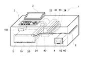
図1は、ラインプリンター1を例に用いて本実施例の液体噴射装置の大まかな構造を示
した説明図である。図示されているように、本実施例のラインプリンター1は、大まかに
は箱型の外形形状をしており、上面には、各種の情報を表示するモニター2や、ユーザー
が操作するための操作パネル3などが設けられている。また、ラインプリンター1の前面
には、インクカートリッジを交換するためのカートリッジ交換扉4や、印刷用紙を装填す
るための給紙扉5が設けられており、更に、向かって右側面には、印刷された印刷用紙が
排出される排紙口6が設けられている。
A. Device configuration :
FIG. 1 is an explanatory diagram showing a rough structure of a liquid ejecting apparatus according to the present embodiment using a
ラインプリンター1の内部には、各種の機能を実行する複数のユニットあるいは部品が
搭載されている。先ず、ラインプリンター1のほぼ中央の位置には、印刷用紙にインクを
噴射するヘッドユニット30が設けられており、ヘッドユニット30の直ぐ下の位置には
印刷用紙を背面から支持するプラテン40(媒体支持部)が設けられている。また、ヘッ
ドユニット30の右下の位置にはカートリッジホルダー60が設けられており、カートリ
ッジホルダー60には、インクが充填されたインクカートリッジ62が装着される。尚、
本実施例のラインプリンター1では、黒インク(Kインク)を使用して白黒印刷を行うラ
インプリンター1を例示しているが、ラインプリンター1は、Kインクの他に、シアンイ
ンク(Cインク)や、マゼンタインク(Mインク)、イエローインク(Yインク)など複
数のインクを用いてカラー印刷を行うプリンターであってもよい。
Inside the
In the
図1の紙面上でヘッドユニット30の左下の位置には、印刷用紙が装填される給紙カセ
ット10が設けられており、給紙カセット10の右端の上面に接する位置に、給紙ローラ
ー20が設けられている。給紙ローラー20の奥側には給紙モーター22が接続されてお
り、給紙モーター22を駆動して給紙ローラー20を回転させると、給紙カセット10か
ら印刷用紙が一枚、ヘッドユニット30に向かって搬送されるようになっている。尚、図
1には、印刷用紙の搬送経路が太い破線で示されている。
A
また、モニターパネル2や操作パネル3が設けられている部分の直ぐ下の位置には、ラ
インプリンター1の各種の動きを制御する制御ユニット100が搭載されている。さらに
、本実施例のラインプリンター1には、図1の紙面上でヘッドユニット30の右隣の位置
に吸引装置50が設けられている。詳細には後述するが、本実施例のラインプリンター1
では、ヘッドユニット30内で増粘したインクを除去する目的でヘッドユニット30から
インクを噴射する動作(フラッシング動作)が行われた際に、噴射されたインクを吸引装
置50によって回収するようになっている。
A
Then, when an operation (flushing operation) of ejecting ink from the
次に、図1を参照しながら本実施例のラインプリンター1の印刷動作を説明する。先ず
、給紙ローラー20によって給紙カセット10から取り出された印刷用紙は、給紙ローラ
ー20とヘッドユニット30との間に設けられたガイドローラー24にガイドされながら
ヘッドユニット30の下方(すなわちプラテン40上)に搬送される。ヘッドユニット3
0は、印刷用紙の搬送経路上に、印刷用紙を跨ぐような状態で設けられており、ヘッドユ
ニット30の底面側(印刷用紙に面する側)には噴射ヘッド(図2を参照)が設けられて
いる。ヘッドユニット30には、カートリッジホルダー60に装着されたインクカートリ
ッジ62から図示しないインク通路を介してインクが供給されており、ヘッドユニット3
0に設けられた噴射ヘッドから印刷用紙に向かってインクが噴射される。
Next, the printing operation of the
No. 0 is provided on the printing paper transport path so as to straddle the printing paper, and an ejection head (see FIG. 2) is provided on the bottom side of the head unit 30 (the side facing the printing paper). It has been. Ink is supplied to the
Ink is ejected from the ejection head provided at 0 toward the printing paper.
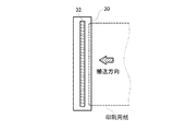
図2は、ヘッドユニット30を底面側から見たときの状態を示す説明図である。図示さ
れるように、本実施例のヘッドユニット30の底面には、細長い略矩形形状をした噴射ヘ
ッド32が設けられており、噴射ヘッド32には、インクを噴射する複数の噴射ノズルが
列状に設けられている。尚、噴射ノズルが設けられている噴射ヘッド32の面を「ノズル
面」と呼ぶことがあるものとする。
FIG. 2 is an explanatory view showing a state when the
このように噴射ヘッド32が設けられたヘッドユニット30からインクが噴射されると
、図1に示した搬送経路を通過中の印刷用紙上に画像が印刷される。こうして画像が印刷
された印刷用紙は、ヘッドユニット30の下流側に設けられたガイドローラー24にガイ
ドされて排紙口6からラインプリンター1の外に排出される。また、前述したように、本
実施例のラインプリンター1には、フラッシング動作によってヘッドユニット30から噴
射されたインクを回収する目的で次のような機構が設けられている。
When ink is ejected from the
B.本実施例のインクの回収機構 :
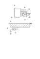
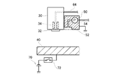
図3は、フラッシング動作によって噴射されたインクを回収する機構の構成を示した説
明図である。図3には、図1に示したラインプリンター1を正面から見たときのヘッドユ
ニット30周辺の構成の縦断面が示されている。
B. Ink recovery mechanism of this embodiment:
FIG. 3 is an explanatory diagram showing a configuration of a mechanism for collecting ink ejected by the flushing operation. FIG. 3 shows a longitudinal section of the configuration around the
本実施例のインクの回収機構は、大まかには、図3の紙面上でヘッドユニット30の右
隣に設けられた吸引装置50(液体吸引手段)と、プラテン40側に設けられた機構など
から構成される。吸引装置50は、プラテン40に向かって開口する吸引口52や、吸引
口52と図示しない廃インク容器とを接続する廃インク通路や、廃インク通路上に設けら
れて、吸引口52に印加するための負圧を発生させる負圧ポンプ54などから構成されて
いる。尚、図3に示されているように、吸引装置50は配線によって接地されている。
The ink recovery mechanism of the present embodiment is roughly based on a suction device 50 (liquid suction means) provided on the right side of the
また、プラテン40は、スイッチ72を介して電源70(電位差発生手段)に接続され
ている。このようなプラテン40側の機構では、スイッチ72をONにしてプラテン40
に電圧(本実施例ではマイナスの電圧)を印加すると、接地した吸引装置50側にプラス
の電荷が誘起されるとともに、プラテン40にマイナスの電荷が誘起されるようになって
いる。
The
When a voltage (a negative voltage in this embodiment) is applied to the platen, a positive charge is induced on the grounded
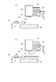
図4は、フラッシング動作によって噴射されたインクを本実施例の回収機構によって回
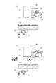
収する様子を示した説明図である。本実施例のラインプリンター1では、印刷中は、前述
した吸引装置50の負圧ポンプ54を停止しておくとともに、プラテン40と電源70と
の間のスイッチ72をOFFにした状態(図3に示した状態)にしておき、この状態で噴
射ノズルから印刷用紙に向かってインクを噴射することで印刷用紙上に画像を印刷する。
FIG. 4 is an explanatory view showing a state in which the ink ejected by the flushing operation is collected by the collection mechanism of the present embodiment. In the
一方、噴射ノズル内でインクの増粘が進み、フラッシング動作を行うことが必要となっ
た場合には、先ず、図4(a)に示されるように、負圧ポンプ54を駆動して吸引口52
からの吸引を開始するとともに、スイッチ72をONにしてプラテン40にマイナスの電
圧を印加する。ここで、本実施例のラインプリンター1では、インク通路64を通ってイ
ンクが噴射ヘッド32まで移動する間に、静電気によってインクがマイナスの電荷に帯電
する。このため、図4(b)に示されるように、プラテン40にマイナスの電圧を印加し
た状態でフラッシング動作を行うと、電気的な反発力によってインクの速度が減速する。
こうして減速したインクに吸引口52からの吸引力が及ぶことで吸引装置50にインクが
吸引される。その結果、フラッシング動作で噴射された全てのインクを回収することがで
きる。また、フラッシング動作によって噴射されたインクがプラテン40に付着すること
を防ぐことができるので、プラテン40上に搬送されてきた印刷用紙が汚れてしまうこと
もない。さらに、フラッシング動作中は、プラテン40と吸引装置50との間に電位差が
発生することにより(図3を参照)、吸引装置50がインクを吸い寄せる方向の電圧が印
加されているので、インクは電気的な引力設けて吸引装置50に回収されるようになって
いる。
On the other hand, when the ink viscosity increases in the ejection nozzle and it becomes necessary to perform the flushing operation, first, as shown in FIG. 52
The suction is started, and the
Ink is sucked into the
このように本実施例のラインプリンター1では、フラッシング動作によって噴射された
全てのインクを回収することができるので、フラッシング動作を実行する際にヘッドユニ
ット30を別の位置に移動させる必要がない。その結果、ヘッドユニット30をキャップ
部材の位置まで移動させた後にキャップ部材に向かってフラッシングを行う必要がないの
で、ヘッドユニット30の移動に伴ってヘッドユニット30の位置ずれが生ずることがな
い。このため、フラッシング動作の前後で同じ位置にインクを噴射することができる。
As described above, in the
また、本実施例のインクの回収機構では、ヘッドユニット30から見て印刷用紙の搬送
経路の下流側に吸引装置50が配置されている。このため、例えば画像の印刷を行わない
部分の印刷用紙を搬送しながらフラッシング動作を行うこととすれば、搬送方向に生じた
気流によって、吸引装置50の方向にインクを移動させることができる。その結果、フラ
ッシング動作によって噴射されたインクをより回収し易くすることが可能となる。
Further, in the ink collecting mechanism of the present embodiment, the
C.変形例 :
前述した実施例には、いくつかの変形例が考えられる。以下では、これらの変形例につ
いて簡単に説明する。尚、以下に説明する変形例において、上述した実施例と同様の構成
部分については、実施例と同様の符号を付し、その詳細な説明を省略する。
C. Modified example:
Several modifications can be considered in the above-described embodiment. Hereinafter, these modified examples will be briefly described. Note that, in the modification described below, the same components as those in the above-described embodiment are denoted by the same reference numerals as those in the embodiment, and detailed description thereof is omitted.
C−1.第1変形例 :
上述した実施例では、噴射ノズルから噴射するインクは、インクがインク通路64を通
ってヘッドユニット30に移動する間の静電気によって帯電するものと説明した。ここで
、インクをより確実に帯電させる目的で、ラインプリンター1にインクを帯電させる機構
を設けることとしてもよい。
C-1. First modification:
In the above-described embodiment, it has been described that the ink ejected from the ejection nozzle is charged by static electricity while the ink moves to the
図5は、第1変形例のインクの回収機構の構成を示した説明図である。図示した回収機
構では、噴射ヘッド32に至るヘッドユニット30の内部通路の途中に、内部通路を通過
するインクをマイナスの電荷に帯電させるための帯電装置34が設けられている。このよ
うな帯電装置34を設けておけば、噴射ノズルから噴射するインクを確実に帯電させるこ
とができるので、プラテン40からの電気的な反発力によって、インクの噴射速度を確実
に減速させることができる。その結果、比較的小さな吸引力でもインクを吸引することが
できるので、負圧ポンプ54を小型化し、延いては吸引装置50の小型化を図ることが可
能となる。
FIG. 5 is an explanatory diagram showing the configuration of the ink collection mechanism of the first modification. In the illustrated recovery mechanism, a charging
C−2.第2変形例 :
上述した実施例および第1変形例では、吸引装置50の負圧ポンプ54は、フラッシン
グ動作を実行するときに駆動するものと説明した。しかし、ラインプリンター1の稼働中
(すなわち電源ONの状態)は、常に負圧ポンプ54を駆動しておくこととしてもよい。
C-2. Second modification:
In the above-described embodiment and the first modification, it has been described that the
負圧ポンプ54の駆動を開始してから吸引装置50によって実際にインクが吸引可能と
なるまでには、ある程度の時間が必要となる。従って、負圧ポンプ54を常時駆動してお
くこととすれば、フラッシング動作を行う場合に、プラテン40をマイナスの電圧に帯電
させるだけで、迅速にフラッシング動作を開始することができる。また、負圧ポンプ54
で発生させる負圧の大きさを調整することにより、吸引装置50の吸引力が印刷中のイン
クの噴射に影響を与えないようにしておけば、吸引によって印刷画質が低下することもな
い。
A certain amount of time is required from the start of driving of the
If the suction force of the
C−3.第3変形例 :
上述した第2変形例では、ラインプリンター1の稼働中は負圧ポンプ54を常時駆動し
ておくことにより、フラッシング動作を迅速に開始可能とするものと説明した。ここで、
負圧ポンプ54を常時駆動する構成を採用する場合には、以下のような構成をラインプリ
ンター1に追加することとしてもよい。
C-3. Third modification:
In the second modification described above, it has been described that the flushing operation can be started quickly by always driving the
When adopting a configuration in which the
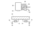
図6は、第3変形例のラインプリンター1のヘッドユニット30周辺の構成を示した説
明図である。図示した第3変形例のラインプリンター1では、図3を用いて前述したライ
ンプリンター1のプラテン40に対して、スイッチ76を介してプラテン40にプラスの
電圧を印加するための電源74が追加されている。このようなラインプリンター1では、
印刷用紙に向かってインクを噴射する場合に、スイッチ76をONにすることでプラテン
40にプラスの電圧を印加することができる。こうすれば、噴射ノズルから噴射したイン
クを印刷用紙の方向により確実に導くことができる。従って、前述したように常時負圧ポ
ンプ54を駆動する構成を採用した場合であっても、噴射されたインクへの影響を考慮し
て吸引装置50の吸引力を抑制する必要がない。その結果、迅速にフラッシング動作を開
始可能としながら、十分な吸引力によって噴射したインクを回収することが可能となる。
FIG. 6 is an explanatory diagram showing a configuration around the
When ink is ejected toward the printing paper, a positive voltage can be applied to the
C−4.第4変形例 :
上述した実施例および変形例では、プラテン40をマイナスの電圧に帯電させることに
より、フラッシング動作によって噴射されたインクの噴射速度を減速させるものと説明し
た。ここで、インクの噴射速度を減速させる構成としては、以下のような構成も考えられ
る。
C-4. Fourth modification:
In the above-described embodiments and modifications, it has been described that the ejection speed of the ink ejected by the flushing operation is reduced by charging the
図7は、第4変形例のインクの回収機構の構成を示した説明図である。図7(a)に示
した第4変形例のインクの回収機構では、前述したように、プラテン40に対して電源7
0の電圧を印加する構成(図3を参照)を採用する代わりに、噴射ノズルとプラテン40
との間で開閉可能に設けられたシャッター機構80のシャッター部材82に対して、電源
70の電圧を印加する構成となっている。
FIG. 7 is an explanatory diagram showing the configuration of the ink collection mechanism of the fourth modified example. In the ink recovery mechanism of the fourth modification shown in FIG. 7A, as described above, the power supply 7 is connected to the
Instead of adopting a configuration in which a voltage of 0 is applied (see FIG. 3), the injection nozzle and the
The voltage of the
このように構成されるインクの回収機構では、印刷中はシャッター部材82をインクの
噴射経路外に退避しておき、フラッシング動作を行う場合には、図7(b)に示されるよ
うに、シャッター部材82を展開した状態でシャッター部材82にマイナスの電荷を誘起
する。これにより、図3を用いて前述した場合と同様に、電気的な反発力によってフラッ
シング動作によって噴射されたインクの速度を減速させることができる。また、図7に示
したインクの回収機構では、フラッシング動作中はシャッター部材82によって噴射ノズ
ルとプラテン40との間が遮られる。従って、仮に負圧ポンプ54が故障したり、あるい
はシャッター部材82に電圧を印加する機構に故障が生ずるなどしてインクの回収に支障
が生じた場合でも、噴射されたインクをシャッター部材82で受け止めることができる。
その結果、噴射されたインクによってプラテン40が汚れることをより確実に回避するこ
とが可能となる。
In the ink collecting mechanism configured as described above, when the
As a result, it is possible to more reliably avoid contamination of the
以上、本願発明の実施例について説明したが、本発明は上記に限られるものではなく、
その要旨を逸脱しない範囲において種々の態様で実施することが可能である。例えば、上
述した実施例および変形例では、フラッシング動作を行う際にはプラテンにマイナスの電
圧を印加するものと説明したが、プラテンに印加する電圧はインクの電荷と同じ極性の電
圧であればよく、インクの電荷がプラスの電荷であれば、プラテンに印加する電圧はプラ
スでもよい。
As mentioned above, although the Example of this invention was described, this invention is not limited above,
The present invention can be implemented in various modes without departing from the gist thereof. For example, in the above-described embodiments and modifications, it has been described that a negative voltage is applied to the platen when performing the flushing operation. However, the voltage applied to the platen may be a voltage having the same polarity as the charge of the ink. If the charge of the ink is positive, the voltage applied to the platen may be positive.
また、上述した実施例および変形例では、プラテン側にインクと同じ極性の電圧を印加
するものと説明したが、この他にも、例えば噴射ヘッド側にインクと逆極性の電圧を印加
するようにしてもよい。こうすれば、フラッシング動作時に噴射したインクをインクの噴
射方向とは逆方向(すなわち噴射ヘッドの方向)に引き戻すことで、インクの速度を減速
させることができる。その結果、プラテン側にインクと同じ極性の電圧を印加した場合と
同様に、吸引装置によってインクを回収し易くすることが可能となる。
In the above-described embodiments and modifications, it has been described that a voltage having the same polarity as the ink is applied to the platen side. However, for example, a voltage having a polarity opposite to that of the ink is applied to the ejection head side. May be. In this way, the ink speed can be reduced by pulling back the ink ejected during the flushing operation in the direction opposite to the ink ejection direction (that is, the direction of the ejection head). As a result, the ink can be easily collected by the suction device as in the case where a voltage having the same polarity as the ink is applied to the platen side.
1…ラインプリンター、 30…ヘッドユニット、 32…噴射ヘッド、
34…帯電装置、 40…プラテン、 50…吸引装置、
52…吸引口、 54…負圧ポンプ、 62…インクカートリッジ、
64…インク通路、 70…電源、 72…スイッチ、
74…電源、 76…スイッチ、 80…シャッター機構、
82…シャッター部材、 100…制御ユニット
1 ... Line printer, 30 ... Head unit, 32 ... Ejecting head,
34 ... Charging device, 40 ... Platen, 50 ... Suction device,
52 ... Suction port, 54 ... Negative pressure pump, 62 ... Ink cartridge,
64 ... ink passage, 70 ... power supply, 72 ... switch,
74 ... Power supply, 76 ... Switch, 80 ... Shutter mechanism,
82 ... Shutter member, 100 ... Control unit
Claims (4)
前記噴射ヘッドから噴射される前記液体を帯電させる液体帯電手段と、
前記噴射ヘッドから帯電された状態で噴射された前記液体が減速する方向の電位差を、
該噴射ヘッドと前記被噴射媒体との間に発生させる電位差発生手段と、
前記噴射ヘッドと前記被噴射媒体との間に存在する前記液体を吸引する液体吸引手段と
を備える液体噴射装置。 A liquid ejecting apparatus that ejects liquid from an ejecting head toward an ejected medium,
Liquid charging means for charging the liquid ejected from the ejection head;
A potential difference in a direction in which the liquid ejected while being charged from the ejection head decelerates,
A potential difference generating means for generating between the ejection head and the ejection medium;
A liquid ejecting apparatus comprising: a liquid sucking unit that sucks the liquid existing between the ejecting head and the ejected medium.
前記噴射ヘッドに対して背面側から前記被噴射媒体を支える媒体支持部を備え、
前記電位差発生手段は、前記噴射ヘッドと前記媒体支持部との間に前記電位差を発生さ
せる手段である液体噴射装置。 The liquid ejecting apparatus according to claim 1,
A medium support part for supporting the ejection medium from the back side with respect to the ejection head;
The liquid ejecting apparatus, wherein the potential difference generating unit is a unit that generates the potential difference between the ejecting head and the medium support unit.
前記液体が噴射される位置から前記被噴射媒体を所定方向に搬送する媒体搬送手段を備
え、
前記液体吸引手段は、前記被噴射媒体が搬送される方向から前記液体を吸引する手段で
ある液体噴射装置。 The liquid ejecting apparatus according to claim 1 or 2,
Medium transport means for transporting the ejected medium in a predetermined direction from a position at which the liquid is ejected;
The liquid ejecting apparatus, wherein the liquid sucking unit is a unit that sucks the liquid from a direction in which the ejected medium is conveyed.
前記電位差発生手段を用いて前記電位差を発生させながら前記液体を噴射する第1動作
状態と、該電位差発生手段の動作を停止して該電位差を発生させることなく前記液体を噴
射する第2動作状態とに切り換える切換制御手段を備える液体噴射装置。 The liquid ejecting apparatus according to any one of claims 1 to 3,
A first operation state in which the liquid is ejected while generating the potential difference using the potential difference generation means; and a second operation state in which the liquid is ejected without generating the potential difference by stopping the operation of the potential difference generation means. A liquid ejecting apparatus comprising switching control means for switching between the two.
Priority Applications (1)
| Application Number | Priority Date | Filing Date | Title |
|---|---|---|---|
| JP2011024683A JP5807335B2 (en) | 2011-02-08 | 2011-02-08 | Liquid ejector |
Applications Claiming Priority (1)
| Application Number | Priority Date | Filing Date | Title |
|---|---|---|---|
| JP2011024683A JP5807335B2 (en) | 2011-02-08 | 2011-02-08 | Liquid ejector |
Publications (2)
| Publication Number | Publication Date |
|---|---|
| JP2012162012A true JP2012162012A (en) | 2012-08-30 |
| JP5807335B2 JP5807335B2 (en) | 2015-11-10 |
Family
ID=46841914
Family Applications (1)
| Application Number | Title | Priority Date | Filing Date |
|---|---|---|---|
| JP2011024683A Expired - Fee Related JP5807335B2 (en) | 2011-02-08 | 2011-02-08 | Liquid ejector |
Country Status (1)
| Country | Link |
|---|---|
| JP (1) | JP5807335B2 (en) |
Citations (5)
| Publication number | Priority date | Publication date | Assignee | Title |
|---|---|---|---|---|
| JPH0483645A (en) * | 1990-07-27 | 1992-03-17 | Canon Inc | Ink jet recorder |
| JP2003094685A (en) * | 2001-09-21 | 2003-04-03 | Hitachi Koki Co Ltd | Inkjet recording device |
| JP2004009471A (en) * | 2002-06-06 | 2004-01-15 | Hitachi Printing Solutions Ltd | Ink jet recording device |
| JP2004058372A (en) * | 2002-07-26 | 2004-02-26 | Hitachi Printing Solutions Ltd | Inkjet recorder |
| JP2010234818A (en) * | 2010-07-30 | 2010-10-21 | Konica Minolta Medical & Graphic Inc | Image recorder |
-
2011
- 2011-02-08 JP JP2011024683A patent/JP5807335B2/en not_active Expired - Fee Related
Patent Citations (5)
| Publication number | Priority date | Publication date | Assignee | Title |
|---|---|---|---|---|
| JPH0483645A (en) * | 1990-07-27 | 1992-03-17 | Canon Inc | Ink jet recorder |
| JP2003094685A (en) * | 2001-09-21 | 2003-04-03 | Hitachi Koki Co Ltd | Inkjet recording device |
| JP2004009471A (en) * | 2002-06-06 | 2004-01-15 | Hitachi Printing Solutions Ltd | Ink jet recording device |
| JP2004058372A (en) * | 2002-07-26 | 2004-02-26 | Hitachi Printing Solutions Ltd | Inkjet recorder |
| JP2010234818A (en) * | 2010-07-30 | 2010-10-21 | Konica Minolta Medical & Graphic Inc | Image recorder |
Also Published As
| Publication number | Publication date |
|---|---|
| JP5807335B2 (en) | 2015-11-10 |
Similar Documents
| Publication | Publication Date | Title |
|---|---|---|
| JP5935338B2 (en) | Image forming apparatus | |
| JP2014108595A (en) | Image formation device | |
| JP2014065293A (en) | Image forming apparatus | |
| JP2009274386A (en) | Liquid droplet discharge device | |
| US9409400B2 (en) | Image forming apparatus configured to include nozzle face capping control | |
| JP2012179814A (en) | Image forming apparatus | |
| JP2015168080A (en) | Liquid ejecting apparatus and maintenance method | |
| JP2016150555A (en) | Liquid discharge device | |
| JP2009262492A (en) | Image forming apparatus | |
| WO2018159044A1 (en) | Recording head restoration system, ink jet recording apparatus provided with same, and recording head restoration method | |
| JP5807335B2 (en) | Liquid ejector | |
| JP5222759B2 (en) | Fluid ejection device and fluid ejection device cleaning method | |
| JP2008246953A (en) | Inkjet recorder | |
| JP5262365B2 (en) | Liquid discharge recording apparatus and ink jet recording apparatus | |
| JP6579090B2 (en) | Recording head and ink jet recording apparatus provided with the same | |
| JP2007283624A (en) | Image forming apparatus | |
| JP2011121260A (en) | Liquid jetting apparatus | |
| JP4860810B2 (en) | Ink jet recording apparatus and discharge recovery method | |
| KR20080093346A (en) | Inkjet image forming apparatus | |
| JP4899490B2 (en) | Droplet discharge device | |
| JP6662279B2 (en) | Printhead recovery system, ink jet printing apparatus including the same, and printhead recovery method | |
| JP6323595B2 (en) | Inkjet recording device | |
| JP5719398B2 (en) | Fluid ejection device | |
| JP2012196932A (en) | Liquid ejection apparatus | |
| JP6135576B2 (en) | Inkjet recording device |
Legal Events
| Date | Code | Title | Description |
|---|---|---|---|
| A621 | Written request for application examination |
Free format text: JAPANESE INTERMEDIATE CODE: A621 Effective date: 20131212 |
|
| A131 | Notification of reasons for refusal |
Free format text: JAPANESE INTERMEDIATE CODE: A131 Effective date: 20140617 |
|
| A977 | Report on retrieval |
Free format text: JAPANESE INTERMEDIATE CODE: A971007 Effective date: 20140618 |
|
| A521 | Request for written amendment filed |
Free format text: JAPANESE INTERMEDIATE CODE: A523 Effective date: 20140812 |
|
| RD04 | Notification of resignation of power of attorney |
Free format text: JAPANESE INTERMEDIATE CODE: A7424 Effective date: 20150106 |
|
| A131 | Notification of reasons for refusal |
Free format text: JAPANESE INTERMEDIATE CODE: A131 Effective date: 20150127 |
|
| A521 | Request for written amendment filed |
Free format text: JAPANESE INTERMEDIATE CODE: A523 Effective date: 20150323 |
|
| TRDD | Decision of grant or rejection written | ||
| A01 | Written decision to grant a patent or to grant a registration (utility model) |
Free format text: JAPANESE INTERMEDIATE CODE: A01 Effective date: 20150811 |
|
| A61 | First payment of annual fees (during grant procedure) |
Free format text: JAPANESE INTERMEDIATE CODE: A61 Effective date: 20150824 |
|
| R150 | Certificate of patent or registration of utility model |
Ref document number: 5807335 Country of ref document: JP Free format text: JAPANESE INTERMEDIATE CODE: R150 |
|
| S531 | Written request for registration of change of domicile |
Free format text: JAPANESE INTERMEDIATE CODE: R313531 |
|
| R350 | Written notification of registration of transfer |
Free format text: JAPANESE INTERMEDIATE CODE: R350 |
|
| LAPS | Cancellation because of no payment of annual fees |