JP2012162017A - Kneader - Google Patents
Kneader Download PDFInfo
- Publication number
- JP2012162017A JP2012162017A JP2011024810A JP2011024810A JP2012162017A JP 2012162017 A JP2012162017 A JP 2012162017A JP 2011024810 A JP2011024810 A JP 2011024810A JP 2011024810 A JP2011024810 A JP 2011024810A JP 2012162017 A JP2012162017 A JP 2012162017A
- Authority
- JP
- Japan
- Prior art keywords
- housing
- shafts
- ring gear
- carrier
- gear
- Prior art date
- Legal status (The legal status is an assumption and is not a legal conclusion. Google has not performed a legal analysis and makes no representation as to the accuracy of the status listed.)
- Granted
Links
- 230000008878 coupling Effects 0.000 claims abstract description 11
- 238000010168 coupling process Methods 0.000 claims abstract description 11
- 238000005859 coupling reaction Methods 0.000 claims abstract description 11
- 238000004898 kneading Methods 0.000 description 7
- 239000002994 raw material Substances 0.000 description 7
- 239000000463 material Substances 0.000 description 3
- 239000011347 resin Substances 0.000 description 3
- 229920005989 resin Polymers 0.000 description 3
- 239000000565 sealant Substances 0.000 description 3
- 238000004140 cleaning Methods 0.000 description 2
- 239000004519 grease Substances 0.000 description 2
- 238000012423 maintenance Methods 0.000 description 2
- 230000002093 peripheral effect Effects 0.000 description 2
- 230000005540 biological transmission Effects 0.000 description 1
- 239000000498 cooling water Substances 0.000 description 1
- 239000008187 granular material Substances 0.000 description 1
- 239000007788 liquid Substances 0.000 description 1
- 238000004519 manufacturing process Methods 0.000 description 1
- 239000000843 powder Substances 0.000 description 1
- 239000002904 solvent Substances 0.000 description 1
- 238000003756 stirring Methods 0.000 description 1
Images
Landscapes
- Processing And Handling Of Plastics And Other Materials For Molding In General (AREA)
- Mixers With Rotating Receptacles And Mixers With Vibration Mechanisms (AREA)
- Mixers Of The Rotary Stirring Type (AREA)
Abstract
Description
本発明は、混練機に関する。 The present invention relates to a kneader.
粉体、粒体、および液体などの原材料を混練する機械として、特許文献1に記載されているような、いわゆる二軸連続式の混練機が知られている。
この種の混練機は、ハウジング内に一対のシャフトを平行に軸支し、両回転シャフトの外周に多数のパドル(攪拌羽根)およびスクリュを取り付けて構成されている。
As a machine for kneading raw materials such as powder, granules, and liquid, a so-called biaxial continuous kneader as described in Patent Document 1 is known.
This type of kneader is configured by supporting a pair of shafts in parallel in a housing and attaching a large number of paddles (stirring blades) and screws to the outer periphery of both rotating shafts.
ハウジングは、その長手方向の一端に投入口が他端に排出口が、それぞれ設けられている。投入口を通じてハウジング内に投入された原材料は、両シャフトの回転に伴い、パドルにより攪拌されまたスクリュにより排出口に向けて送られて、最終的にその排出口から混練物が排出されることになる。 The housing is provided with an input port at one end in the longitudinal direction and a discharge port at the other end. The raw materials introduced into the housing through the inlet are agitated by the paddles and sent to the outlet by the screw as the two shafts rotate, and finally the kneaded material is discharged from the outlet. Become.
ここで原材料として、樹脂溶液など漏洩しやすいものが選択される場合には、ハウジング内に高い気密性が要求されるため、シャフトに軸シールが用いられる。
二軸連続式の混練機の場合には、高真空用の軸シールとしてメカニカルシールを用いるのが一般的である。
Here, when a material that easily leaks, such as a resin solution, is selected as a raw material, since a high airtightness is required in the housing, a shaft seal is used for the shaft.
In the case of a biaxial continuous kneader, a mechanical seal is generally used as a shaft seal for high vacuum.
しかし通常は、メカニカルシールは構造が複雑であるためコストが嵩むし、混練機全体の大型化にもつながる。特にセルフクリーニング型の二軸混練機の場合、軸間距離が一定以内に制限されるため、シールの種類が限られるとともに高い機密性を保つためには特殊な設計が必要となり、一層コスト高となる。
またメカニカルシールの場合、その内部圧力を制御するシーラントの管理が必要となるため、シーラントの供給循環装置のメインテナンスにも手間とコストがかかる。
However, the mechanical seal usually has a complicated structure, which increases costs and leads to an increase in the size of the entire kneader. In particular, in the case of a self-cleaning type twin-screw kneader, the distance between the shafts is limited within a certain range, so the types of seals are limited and a special design is required to maintain high confidentiality, which further increases the cost. Become.
Further, in the case of a mechanical seal, since it is necessary to manage a sealant that controls its internal pressure, maintenance of the sealant supply and circulation device also takes time and cost.
そこで本発明の解決すべき課題は、二軸連続式の混練機について、メカニカルシールを用いることなく、ハウジング内の気密性を簡易な手段で確保することである。 Therefore, the problem to be solved by the present invention is to ensure airtightness in the housing with a simple means without using a mechanical seal for the biaxial continuous kneader.
上記した課題を解決するため、発明にかかる混練機では、シャフトを含むハウジング内の機構とハウジング外に配置された回転駆動するキャリアとの間に磁気カップリングを形成することで、シャフトをハウジングに密封された状態で回転可能としたのである。 In order to solve the above-described problems, in the kneader according to the invention, a magnetic coupling is formed between the mechanism in the housing including the shaft and the rotationally driven carrier disposed outside the housing, so that the shaft is attached to the housing. It can be rotated in a sealed state.
より具体的には、発明にかかる混練機を、長手方向の一端に投入口を有し他端に排出口を有するハウジングと、前記ハウジング内にハウジング長手方向に沿って平行にかつ回転可能に支持されかつ密封され、外周にその軸方向に並列する複数のパドルおよびスクリュを有する一対のシャフトと、前記両シャフトを回転させる磁気カップリング機構と、を備え、前記磁気カップリング機構は、両シャフトの軸端に互いに軸方向に間隔をあくように設けられたギア部と、前記ハウジング内に両シャフトの軸端の外周に被さるように回転可能に支持され、その内周に前記両シャフトのギア部にそれぞれかみ合うギア部を有し、その外周にマグネット部を有する円筒形のリングギアと、前記ハウジング外に前記リングギアと同心上に回転可能に支持され、その内周にマグネット部を有する円筒形のキャリアと、からなる構成を採用したのである。 More specifically, the kneader according to the invention is supported in a housing that has an inlet at one end in the longitudinal direction and an outlet at the other end, and is rotatably supported in the housing along the longitudinal direction of the housing. And a pair of shafts having a plurality of paddles and screws arranged in parallel in the axial direction on the outer periphery, and a magnetic coupling mechanism for rotating both the shafts, the magnetic coupling mechanism comprising: A gear portion provided at the shaft end so as to be spaced apart from each other in the axial direction, and a gear portion of the shafts of the both shafts which are rotatably supported in the housing so as to cover the outer periphery of the shaft ends of the shafts. And a cylindrical ring gear having a magnet portion on the outer periphery thereof, and rotatably supported concentrically with the ring gear outside the housing. It was adopted as a carrier of a cylindrical shape having a magnet portion its inner periphery, a structure consisting of.
発明にかかる混練機を以上のように構成して、ハウジング外のキャリアを駆動させると、対向するマグネット部間の磁力の作用で、ハウジング内のリングギアが回転し、ついでギア部同士のかみ合いにより、シャフトが回転する。
ハウジングの内外で磁気カップリング機構を形成し、シャフトをハウジングに密封した状態で回転可能に構成したので、簡易な手段で機密性が確保される。
When the kneader according to the invention is configured as described above and the carrier outside the housing is driven, the ring gear in the housing rotates due to the action of the magnetic force between the opposing magnet parts, and then the gear parts mesh with each other. The shaft rotates.
Since the magnetic coupling mechanism is formed inside and outside the housing and is configured to be rotatable with the shaft sealed in the housing, confidentiality is ensured by simple means.
以下、図面を参照しつつ本発明の実施形態について説明する。 Hereinafter, embodiments of the present invention will be described with reference to the drawings.
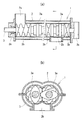
図1に示す実施形態の混練機1は、溶媒中で重合される樹脂や脱モノマーが必要な樹脂溶液など、漏洩しやすく気密性が要求される原材料を混練する際に好適に用いられる。
図示のように、混練機1は、ハウジング2と、ハウジング2内に密封される一対のシャフト3と、を備える。
さらに混練機1は、シャフト3を回転させるための磁気カップリング機構を備える。
The kneading machine 1 of the embodiment shown in FIG. 1 is suitably used when kneading raw materials that are likely to leak and require airtightness, such as a resin that is polymerized in a solvent or a resin solution that requires demonomerization.
As illustrated, the kneading machine 1 includes a
Further, the kneader 1 includes a magnetic coupling mechanism for rotating the
図1のように、二連円筒形のハウジング2は、その外周面の一端上部に原材料の投入口2aを有し、外周面の他端下部に混練物の排出口2bを有する。
また、ハウジング2の長手方向の端部には、軸受が組み込まれた軸受箱2cが取り付けられている。
As shown in FIG. 1, the double
In addition, a
一対の回転シャフト3は、2連円筒形をなすハウジング2の各円筒内にハウジング2の長手方向に沿ってそれぞれ配置され、平行をなしている。
各回転シャフト3は、ハウジング2両端面の軸受箱2c内の軸受2dにより回転可能に支持されており、その外周には軸方向に並列する複数のパドル3aおよびスクリュ3bが取り付けられている。軸受箱2cとシャフト3の間は、オイルシール2eがなされている。
The pair of rotating
Each
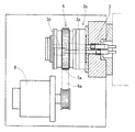
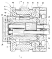
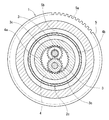
図2から図4のように、ハウジング2の軸受箱2cに収納された両シャフト3の軸端には、それぞれギア部3cが設けられている。両ギア部3cはシャフト3の軸方向に間隔をあけて設けられており、互いに干渉しないようになっている。
As shown in FIGS. 2 to 4,
また、ハウジング2の軸受箱2c内には、両シャフト3の軸端に被さるように、円筒形のリングギア4が回転可能に支持されている。軸受箱2cとリングギア4の間は、オイルシール2fがなされている。
リングギア4は、その内周にギア部4aを有し、両シャフト3のギア部3cのそれぞれとかみ合っている。また、その外周には永久磁石が固定されて、円筒状のマグネット部4bが形成されている。
A
The
さらに、軸受箱2cの外には、リングギア4と同心上に円筒形のキャリア5が回転可能に支持されている。
キャリア5は、その外周にギア部5aを有し、その内周に永久磁石が固定されて、円筒状のマグネット部5bが形成されている。軸受箱2cとキャリア5の間は、オイルシール2gがなされている。
Further, a
The
図2のように、キャリア5と電動機6に、タイミングベルト6aが掛け渡され、電動機6からキャリア5に回転が伝達されるようになっている。
なお、軸受箱2c内には、グリスの供給排出口2hおよび冷却水の流路が適宜設けられているものとする。
As shown in FIG. 2, a
It is assumed that a grease supply /
実施形態の混練機の構成は以上のようであり、ハウジング2の外にあるキャリア5が回転すると、ハウジング2の内にあるリングギア4は、マグネット部5bとマグネット部4b間の磁力の作用により、キャリア5とともに回転を開始する。
The configuration of the kneading machine of the embodiment is as described above. When the
リングギア4が回転すると、ギア部4aとギア部3cとのかみ合いにより、両シャフト3は同方向に回転を開始する。
このようにして磁気カップリング機構は、軸受箱2cの内部にあるシャフト3のギア部3cおよびリングギア4、ならびに壁を隔てて軸受箱2cの外部にあるキャリア5、から構成されている。
When the
In this way, the magnetic coupling mechanism includes the
ここでハウジング2の投入口2aから原材料を投入すると、シャフト3と一体に回転するパドル3aにより原材料は攪拌されて混練物となる。これがシャフト3と一体に回転するスクリュ3bによりハウジング2内を排出口2bに向けて送られ、最後は排出口2bから混練物が排出されることになる。
Here, when the raw material is charged from the
シャフト3はハウジング2内に密封され、磁気カップリング機構を用いて壁を隔てて動力伝達をおこなうため、簡易な構成で気密性が確保される。
簡易な構成であるため、気密性確保のためメカニカルシール等を用いる場合に比べて、製造コストを抑えられ、また混練機1全体の小型化が図られる。
小型化が図られるため、セルフクリーニング型の二軸混練機のような、軸間距離が一定以内に制限される場合にも、メカニカルシールと異なり、特殊な設計を必要としない。
メカニカルシールのようなシーラントの管理が不要であるため、メインテナンスの手間と費用も抑えることができる。
Since the
Since the structure is simple, the manufacturing cost can be suppressed and the size of the entire kneader 1 can be reduced as compared with the case where a mechanical seal or the like is used to ensure airtightness.
Since a reduction in size is achieved, unlike a mechanical seal, a special design is not required even when the distance between axes is limited within a certain range, such as a self-cleaning type twin-screw kneader.
Since management of a sealant such as a mechanical seal is unnecessary, maintenance labor and costs can be reduced.
1 実施形態の混練機
2 ハウジング
2a 投入口
2b 排出口
2c 軸受箱
2d 軸受
2e、2f、2g オイルシール
2g グリス供給排出口
3 シャフト
3a パドル
3b スクリュ
3c ギア部
4 リングギア
4a ギア部
4b マグネット部
5 キャリア
5a ギア部
5b マグネット部
6 電動機
6a タイミングベルト
DESCRIPTION OF SYMBOLS 1
Claims (1)
前記ハウジング2内にハウジング長手方向に沿って平行にかつ回転可能に支持されかつ密封され、外周にその軸方向に並列する複数のパドル3aおよびスクリュ3bを有する一対のシャフト3と、
前記両シャフト3を回転させる磁気カップリング機構と、を備え、
前記磁気カップリング機構は、
前記両シャフト3の軸端に互いに軸方向に間隔をあくように設けられたギア部3cと、
前記ハウジング2内に両シャフト3の軸端の外周に被さるように回転可能に支持され、その内周に前記両シャフト3のギア部3cにそれぞれかみ合うギア部4aを有し、その外周にマグネット部4bを有する円筒形のリングギア4と、
前記ハウジング2外に前記リングギア4と同心上に回転可能に支持され、その内周にマグネット部5bを有する円筒形のキャリア5と、からなる混練機。 A housing 2 having an inlet 2a at one end in the longitudinal direction and an outlet 2b at the other end;
A pair of shafts 3 having a plurality of paddles 3a and screws 3b which are supported and sealed in parallel in the longitudinal direction of the housing 2 in the housing 2 and sealed, and arranged on the outer periphery in parallel in the axial direction;
A magnetic coupling mechanism for rotating the shafts 3;
The magnetic coupling mechanism is
Gear portions 3c provided at axial ends of the shafts 3 so as to be spaced apart from each other in the axial direction;
The housing 2 is rotatably supported so as to cover the outer periphery of the shaft ends of both shafts 3, and has gear portions 4 a that mesh with the gear portions 3 c of the both shafts 3 on the inner periphery, and a magnet portion on the outer periphery thereof. A cylindrical ring gear 4 having 4b;
A kneader comprising: a cylindrical carrier 5 that is rotatably supported concentrically with the ring gear 4 outside the housing 2 and has a magnet portion 5b on the inner periphery thereof.
Priority Applications (1)
| Application Number | Priority Date | Filing Date | Title |
|---|---|---|---|
| JP2011024810A JP5466186B2 (en) | 2011-02-08 | 2011-02-08 | Kneading machine |
Applications Claiming Priority (1)
| Application Number | Priority Date | Filing Date | Title |
|---|---|---|---|
| JP2011024810A JP5466186B2 (en) | 2011-02-08 | 2011-02-08 | Kneading machine |
Publications (2)
| Publication Number | Publication Date |
|---|---|
| JP2012162017A true JP2012162017A (en) | 2012-08-30 |
| JP5466186B2 JP5466186B2 (en) | 2014-04-09 |
Family
ID=46841918
Family Applications (1)
| Application Number | Title | Priority Date | Filing Date |
|---|---|---|---|
| JP2011024810A Active JP5466186B2 (en) | 2011-02-08 | 2011-02-08 | Kneading machine |
Country Status (1)
| Country | Link |
|---|---|
| JP (1) | JP5466186B2 (en) |
Cited By (2)
| Publication number | Priority date | Publication date | Assignee | Title |
|---|---|---|---|---|
| CN104175410A (en) * | 2014-08-02 | 2014-12-03 | 青岛科高橡塑机械技术装备有限公司 | Novel dual experimental mixer |
| CN116277582A (en) * | 2023-04-14 | 2023-06-23 | 南通范氏机械有限公司 | A kind of continuous kneading machine and kneading method |
Families Citing this family (1)
| Publication number | Priority date | Publication date | Assignee | Title |
|---|---|---|---|---|
| CN110201570A (en) * | 2019-05-23 | 2019-09-06 | 佛山市思特四通化工有限公司 | A kind of Production of Ceramics mica powder process equipment and preparation method thereof |
Citations (5)
| Publication number | Priority date | Publication date | Assignee | Title |
|---|---|---|---|---|
| JPH02194826A (en) * | 1989-01-23 | 1990-08-01 | Nikku Ind Co Ltd | Continuous mixer without shaft seal mechanism |
| JPH02265635A (en) * | 1989-04-04 | 1990-10-30 | Satake Kagaku Kikai Kogyo Kk | Rotating driving gear |
| JPH037306A (en) * | 1989-06-05 | 1991-01-14 | Ube Ind Ltd | Driving device of biaxial kneader |
| JP2006521942A (en) * | 2003-04-03 | 2006-09-28 | ブラッハ、ヨーゼフ・アー | Gear device for driving a multi-shaft extruder |
| JP2011519756A (en) * | 2008-05-07 | 2011-07-14 | ブラハ・フェアバルツングス・ゲーエムベーハー・ウント・コー・カーゲー | Extruder transmission device |
-
2011
- 2011-02-08 JP JP2011024810A patent/JP5466186B2/en active Active
Patent Citations (5)
| Publication number | Priority date | Publication date | Assignee | Title |
|---|---|---|---|---|
| JPH02194826A (en) * | 1989-01-23 | 1990-08-01 | Nikku Ind Co Ltd | Continuous mixer without shaft seal mechanism |
| JPH02265635A (en) * | 1989-04-04 | 1990-10-30 | Satake Kagaku Kikai Kogyo Kk | Rotating driving gear |
| JPH037306A (en) * | 1989-06-05 | 1991-01-14 | Ube Ind Ltd | Driving device of biaxial kneader |
| JP2006521942A (en) * | 2003-04-03 | 2006-09-28 | ブラッハ、ヨーゼフ・アー | Gear device for driving a multi-shaft extruder |
| JP2011519756A (en) * | 2008-05-07 | 2011-07-14 | ブラハ・フェアバルツングス・ゲーエムベーハー・ウント・コー・カーゲー | Extruder transmission device |
Cited By (2)
| Publication number | Priority date | Publication date | Assignee | Title |
|---|---|---|---|---|
| CN104175410A (en) * | 2014-08-02 | 2014-12-03 | 青岛科高橡塑机械技术装备有限公司 | Novel dual experimental mixer |
| CN116277582A (en) * | 2023-04-14 | 2023-06-23 | 南通范氏机械有限公司 | A kind of continuous kneading machine and kneading method |
Also Published As
| Publication number | Publication date |
|---|---|
| JP5466186B2 (en) | 2014-04-09 |
Similar Documents
| Publication | Publication Date | Title |
|---|---|---|
| JP5466186B2 (en) | Kneading machine | |
| CN105921224B (en) | A kind of dispersed grinder of multi-functional middle capacity and its method of work | |
| CN212680781U (en) | Novel heated board powder mixes device | |
| WO2013183100A1 (en) | Kneading machine | |
| JP5173787B2 (en) | Dust seal structure of hermetic kneader | |
| CN104668029A (en) | Chemical material grinding device and using method thereof | |
| KR20170004562A (en) | Mixer For Complex Material | |
| TWI531457B (en) | Rotor for kneading and kneading machine | |
| CN205627809U (en) | Two dimensional motion mixer is used in medicine processing | |
| CN104190303A (en) | Stirring device | |
| CN104260203B (en) | Decelerating mechanism for vertical axis planetary stirrer | |
| CN203281264U (en) | Stirrer | |
| JP2014001714A (en) | Uniaxial eccentric screw pump | |
| CN204841513U (en) | Low temperature agitating unit | |
| CN220589750U (en) | Mineral powder mixing equipment | |
| JP2016028799A (en) | Kneading and stirring device | |
| CN104542771A (en) | Dough mixer | |
| CN105561861B (en) | A kind of mixer discharging sealing device | |
| CN208612349U (en) | A kind of fluid mixer | |
| CN203725150U (en) | Fully sealed acid pickling kettle adopting internal rotor stirring | |
| CN203803417U (en) | Disc heating and stirring distributor | |
| CN206254350U (en) | A kind of material mixing device | |
| CN208177278U (en) | Blender and industrial equipment with the blender | |
| CN211133744U (en) | Vertical mixer is used in chemical fertilizer production | |
| CN104998573A (en) | Low-temperature stirring device and low-temperature stirring method |
Legal Events
| Date | Code | Title | Description |
|---|---|---|---|
| A621 | Written request for application examination |
Free format text: JAPANESE INTERMEDIATE CODE: A621 Effective date: 20121010 |
|
| A977 | Report on retrieval |
Free format text: JAPANESE INTERMEDIATE CODE: A971007 Effective date: 20131211 |
|
| TRDD | Decision of grant or rejection written | ||
| A01 | Written decision to grant a patent or to grant a registration (utility model) |
Free format text: JAPANESE INTERMEDIATE CODE: A01 Effective date: 20140107 |
|
| A61 | First payment of annual fees (during grant procedure) |
Free format text: JAPANESE INTERMEDIATE CODE: A61 Effective date: 20140123 |
|
| R150 | Certificate of patent or registration of utility model |
Ref document number: 5466186 Country of ref document: JP Free format text: JAPANESE INTERMEDIATE CODE: R150 Free format text: JAPANESE INTERMEDIATE CODE: R150 |