JP2012162108A - Vehicle front structure - Google Patents
Vehicle front structure Download PDFInfo
- Publication number
- JP2012162108A JP2012162108A JP2011022000A JP2011022000A JP2012162108A JP 2012162108 A JP2012162108 A JP 2012162108A JP 2011022000 A JP2011022000 A JP 2011022000A JP 2011022000 A JP2011022000 A JP 2011022000A JP 2012162108 A JP2012162108 A JP 2012162108A
- Authority
- JP
- Japan
- Prior art keywords
- vehicle
- panel member
- crash box
- width direction
- vehicle front
- Prior art date
- Legal status (The legal status is an assumption and is not a legal conclusion. Google has not performed a legal analysis and makes no representation as to the accuracy of the status listed.)
- Pending
Links
Images







Landscapes
- Body Structure For Vehicles (AREA)
Abstract
【課題】車両走行時にクラッシュボックスに左右モーメントが作用した際に、クラッシュボックスの左右方向への変形を抑制することができる車両前部構造を得る。
【解決手段】フロントサイドメンバ12とフロントバンパリインフォースメント24との間に左右一対のクラッシュボックス16が設けられている。クラッシュボックス16は、筒状の衝撃吸収部18と連結板20とを備えている。衝撃吸収部18は、車両内向きに開口される断面略コ字状の第1パネル部材30と、車両外向きに開口される断面略コ字状の第2パネル部材32とを備えており、第1パネル部材30と第2パネル部材32の上下の重ね部34、36がスポット溶接40により接合され、閉断面とされている。車両平面視にて衝撃吸収部18は左右対称であり、上下の重ね部34、36における溶接部は、左右一対のクラッシュボックス16の異なる対角方向に配置されている。
【選択図】図1A vehicle front structure capable of suppressing deformation of a crash box in the left-right direction when a left-right moment is applied to the crash box during vehicle travel is obtained.
A pair of left and right crash boxes 16 are provided between a front side member 12 and a front bumper reinforcement 24. The crash box 16 includes a cylindrical impact absorbing portion 18 and a connecting plate 20. The shock absorbing portion 18 includes a first panel member 30 having a substantially U-shaped cross section that is opened inward of the vehicle, and a second panel member 32 having a substantially U-shaped cross section that is opened outward of the vehicle. The upper and lower overlapping portions 34 and 36 of the first panel member 30 and the second panel member 32 are joined by spot welding 40 to form a closed cross section. The impact absorbing portion 18 is bilaterally symmetric in plan view of the vehicle, and the welded portions in the upper and lower overlapping portions 34 and 36 are arranged in different diagonal directions of the pair of left and right crash boxes 16.
[Selection] Figure 1
Description
本発明は、車両前部構造に関する。 The present invention relates to a vehicle front structure.
下記特許文献1には、それぞれ断面凹み形状に屈曲してなる第1パネル部材と第2パネル部材の両端部同士を、断面凹み形状を向かい合わせにした状態で重畳して接合することにより、車両前後方向に延在する閉断面を形成したクラッシュボックス構造が開示されている。 In the following Patent Document 1, a vehicle is obtained by overlapping and joining both end portions of a first panel member and a second panel member that are bent into a cross-sectionally recessed shape with the cross-sectionally recessed shapes facing each other. A crash box structure having a closed cross section extending in the front-rear direction is disclosed.
上記特許文献1に記載の構造では、断面の効率化や高張力鋼板の使用により、クラッシュボックスが薄肉化された場合に、剛性の低下が懸念される。例えば、車両走行時にクラッシュボックスに左右モーメントが作用した際、車両平面視にて略長方形状のクラッシュボックスが容易に略平行四辺形状に変形しやすくなり、操縦安定性に影響する。 In the structure described in Patent Document 1, when the crash box is thinned due to the efficiency of the cross section or the use of a high-tensile steel plate, there is a concern that the rigidity may be lowered. For example, when a left / right moment acts on the crash box when the vehicle is traveling, the substantially rectangular crash box is easily deformed into a substantially parallelogram in a plan view of the vehicle, which affects steering stability.
本発明は上記事実を考慮し、車両走行時にクラッシュボックスに左右モーメントが作用した際に、クラッシュボックスの左右方向への変形を抑制することができる車両前部構造を得ることが目的である。 An object of the present invention is to obtain a vehicle front structure that can suppress the deformation of the crash box in the left-right direction when a left-right moment is applied to the crash box when the vehicle is traveling.
請求項1の発明に係る車両前部構造は、車両前部において車両前後方向に延在される左右一対のサイドメンバと、前記サイドメンバに対して車両前方側に設けられ、車両幅方向に沿って配設されるバンパリインフォースと、前記サイドメンバと前記バンパリインフォースとの間に設けられ、車両幅方向外側に配置される断面略コ字状の第1パネル部材と、車両幅方向内側に配置される断面略コ字状の第2パネル部材とを備えると共に、前記第1パネル部材と前記第2パネル部材との両端部同士を車両上下面に設けられた重ね部で接合して車両前後方向に延在する閉断面が形成される左右一対のクラッシュボックスと、を有すると共に、前記重ね部における接合部が、車両平面視において左右一対の前記クラッシュボックスの異なる対角方向に配置されているものである。 The vehicle front structure according to the invention of claim 1 is provided on the front side of the vehicle with respect to the pair of left and right side members extending in the vehicle front-rear direction at the vehicle front portion, and along the vehicle width direction. A bumper reinforcement disposed between the side member and the bumper reinforcement, a first panel member having a substantially U-shaped cross section disposed on the outer side in the vehicle width direction, and disposed on the inner side in the vehicle width direction. A second panel member having a substantially U-shaped cross section, and joining both ends of the first panel member and the second panel member with overlapping portions provided on the upper and lower surfaces of the vehicle in the vehicle longitudinal direction. A pair of left and right crash boxes in which an extended closed cross section is formed, and the joint portion in the overlapping portion is in a different diagonal direction of the pair of left and right crash boxes in a vehicle plan view. Those which are location.
請求項2の発明は、請求項1に記載の車両前部構造において、前記重ね部における接合部は、車両平面視において車両前方に開くハの字状に配置されているものである。 According to a second aspect of the present invention, in the vehicle front portion structure according to the first aspect, the joint portion in the overlapping portion is arranged in a square shape that opens forward of the vehicle in a plan view of the vehicle.
請求項3の発明は、請求項1又は請求項2に記載の車両前部構造において、前記重ね部における接合部は、不連続溶接により接合され、その溶接部間の少なくとも一部に前記クラッシュボックスの長手方向と直交する段部が設けられているものである。 According to a third aspect of the present invention, in the vehicle front portion structure according to the first or second aspect, the joint portion in the overlap portion is joined by discontinuous welding, and the crash box is provided at least at a part between the weld portions. The step part orthogonal to the longitudinal direction is provided.
請求項1記載の本発明によれば、サイドメンバとバンパリインフォースとの間に設けられる左右一対のクラッシュボックスは、車両幅方向外側に配置される断面略コ字状の第1パネル部材と、車両幅方向内側に配置される断面略コ字状の第2パネル部材とを備えており、第1パネル部材と第2パネル部材との両端部同士を車両上下面に設けられた重ね部で接合して車両前後方向に延在する閉断面とされている。クラッシュボックスの第1パネル部材と第2パネル部材との重ね部における接合部を、車両平面視において左右一対のクラッシュボックスの異なる対角方向に配置することで、クラッシュボックスの図心がクラッシュボックスの長手方向(軸方向)に対して傾いて設定される。これによって、走行による左右モーメントが作用した際に、左右一対のうちの一方のクラッシュボックスの図心は仮想的に伸び、他方のクラッシュボックスの図心は仮想的に縮むため、左右一対のクラッシュボックスで図心の線長が異なることになる。したがって、横変形時の左右のクラッシュボックスの図心の回転半径が異なり、クラッシュボックスが左右方向に変形しにくい。 According to the first aspect of the present invention, the pair of left and right crash boxes provided between the side member and the bumper reinforcement includes a first panel member having a substantially U-shaped cross section disposed outside the vehicle width direction, and the vehicle. A second panel member having a substantially U-shaped cross section disposed on the inner side in the width direction, and joining both ends of the first panel member and the second panel member with overlapping portions provided on the upper and lower surfaces of the vehicle. Thus, the cross section extends in the vehicle longitudinal direction. The centroid of the crash box is made to be the centroid of the crash box by arranging the joint portion in the overlapping portion of the first panel member and the second panel member of the crash box in different diagonal directions of the pair of left and right crash boxes in the vehicle plan view. It is set to be inclined with respect to the longitudinal direction (axial direction). As a result, when the left and right moments due to running are applied, the centroid of one of the left and right crash boxes virtually expands and the centroid of the other crash box virtually contracts. The centroid line length will be different. Therefore, the rotation radii of the centroids of the left and right crash boxes at the time of lateral deformation are different, and the crash boxes are difficult to deform in the left-right direction.
請求項2記載の本発明によれば、クラッシュボックスの第1パネル部材と第2パネル部材との重ね部における接合部が、車両平面視において車両前方に開くハの字状に配置されていることで、車両の斜め外方向からの衝突に対してクラッシュボックスの図心の方向で荷重を受けることができ、クラッシュボックスを曲げずに軸圧縮変形させることができる。 According to the second aspect of the present invention, the joint portion in the overlapping portion of the first panel member and the second panel member of the crash box is arranged in a square shape that opens forward in the vehicle plan view. Thus, it is possible to receive a load in the direction of the centroid of the crash box with respect to a collision from the obliquely outward direction of the vehicle, and to axially deform the crash box without bending it.
請求項3記載の本発明によれば、クラッシュボックスの第1パネル部材と第2パネル部材との重ね部における接合部が、不連続溶接により接合され、その溶接部間の少なくとも一部にクラッシュボックスの長手方向と直交する段部が設けられており、クラッシュボックスを段部で長手方向に変形させることができる。したがって、重ね部における接合部をクラッシュボックスの稜線に対し斜めに設けても、衝突時にクラッシュボックスをより確実に軸圧壊させることができる。 According to this invention of Claim 3, the junction part in the overlap part of the 1st panel member and 2nd panel member of a crash box is joined by discontinuous welding, and a crash box is at least partially between the weld parts. A step portion orthogonal to the longitudinal direction is provided, and the crush box can be deformed in the longitudinal direction at the step portion. Therefore, even if the joint portion in the overlapping portion is provided obliquely with respect to the ridge line of the crash box, the crash box can be more reliably axially collapsed at the time of collision.
以上説明したように、請求項1記載の本発明に係る車両前部構造は、車両走行時にクラッシュボックスに左右モーメントが作用した際に、クラッシュボックスの左右方向への変形を抑制することができるという優れた効果を有する。 As described above, the vehicle front structure according to the first aspect of the present invention can suppress deformation of the crash box in the left-right direction when a left-right moment is applied to the crash box during vehicle travel. Has an excellent effect.
請求項2記載の本発明に係る車両前部構造は、車両の斜め外方向からの衝突に対してクラッシュボックスを曲げずに軸圧縮変形させることができるという優れた効果を有する。 The vehicle front structure according to the second aspect of the present invention has an excellent effect that the crash box can be subjected to axial compression deformation without bending the crash box against a collision from the oblique outer direction of the vehicle.
請求項3記載の本発明に係る車両前部構造は、衝突時にクラッシュボックスをより確実に軸圧壊させることができるという優れた効果を有する。 The vehicle front structure according to the third aspect of the present invention has an excellent effect that the crash box can be more reliably axially collapsed in the event of a collision.
以下、図1〜図8を用いて、本発明に係る車両前部構造の第1実施形態について説明する。なお、これらの図において適宜示される矢印FRは車両前方側を示しており、矢印UPは車両上方側を示しており、矢印OUTは車両幅方向外側を示している。 Hereinafter, a first embodiment of a vehicle front structure according to the present invention will be described with reference to FIGS. In these drawings, an arrow FR appropriately shown indicates the vehicle front side, an arrow UP indicates the vehicle upper side, and an arrow OUT indicates the vehicle width direction outer side.
図1には、本実施形態に係る車両前部構造が適用された車両の前部が示されている。この図に示されるように、自動車の車両10の前部両サイドには、車両前後方向に延在する車両骨格部材としての左右一対のフロントサイドメンバ(サイドメンバ)12が配設されている。フロントサイドメンバ12の車両前方には、補強板14を挟んで衝撃吸収部材としてのクラッシュボックス16が配設されている。クラッシュボックス16は、衝突荷重の入力時に軸方向に圧縮変形することによって衝突エネルギーを吸収する筒状の衝撃吸収部18と、この衝撃吸収部18を補強板14に取り付けるための連結板20と、を備えている。
FIG. 1 shows a front portion of a vehicle to which the vehicle front structure according to the present embodiment is applied. As shown in this figure, a pair of left and right front side members (side members) 12 as vehicle skeleton members extending in the vehicle front-rear direction are disposed on both front sides of a
クラッシュボックス16の車両前方側には、車両幅方向に延在するバンパ骨格部材としてのフロントバンパリインフォースメント(バンパリインフォース)24がブラケット22を介して取り付けられている。すなわち、クラッシュボックス16は、車両平面視にてフロントサイドメンバ12とフロントバンパリインフォースメント24との間に、ブラケット22、補強板14を介して設けられている。フロントサイドメンバ12、補強板14、衝撃吸収部18と連結板20とを備えたクラッシュボックス16、ブラケット22は、車両幅方向一端側と他端側に各1個ずつ左右対称に設けられている。なお、フロントバンパリインフォースメント24の車両前方側には、車両幅方向に沿ってフロントバンパカバー(図示省略)が取り付けられている。
A front bumper reinforcement (bumper reinforcement) 24 as a bumper skeleton member extending in the vehicle width direction is attached to the front side of the
フロントサイドメンバ12は、車両前後方向の断面形状が中空矩形である筒状のフレームで構成されており、フロントサイドメンバ12の車両前後方向の前端部12Aを閉塞するように車両幅方向に沿って補強板14が取り付けられている。補強板14は、フロントサイドメンバ12の前端部12Aに溶接等により結合されている。
The
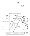
図2〜図4に示されるように、クラッシュボックス16の衝撃吸収部18は、車両幅方向外側に配置される第1パネル部材30と、車両幅方向内側に配置される第2パネル部材32と、を備えている。図2、図3では、車両正面視にて車両幅方向左側に配置されるクラッシュボックス16が図示されている。左右一対のクラッシュボックス16(衝撃吸収部18)は、左右対称に形成されているため、車両正面視にて車両幅方向右側に配置されるクラッシュボックス16については図示を省略する。
As shown in FIGS. 2 to 4, the
第1パネル部材30は、車両前後方向に沿って配置される断面略コ字状の部材であり、車両幅方向内向きに開口されている。すなわち、第1パネル部材30は、車両幅方向に沿って配置される上面部30Aと、上面部30Aの車両幅方向外側端部から車両下方に沿って配置される縦壁部30Bと、縦壁部30Bの下端部から車両幅方向内側に沿って配置される下面部30Cと、を備えている。上面部30Aの内側端縁と下面部30Cの内側端縁は、前端部から車両後方側に向かって車両幅方向内側に延出するように斜め方向に形成されている。言い換えると、上面部30Aの内側端縁と下面部30Cの内側端縁は、車両平面視にて略長方形状のクラッシュボックス16の略対角方向であって、前端部が車両幅方向外側で後端部が車両幅方向内側となるように配置されている。
The
第2パネル部材32は、車両前後方向に沿って配置される断面略コ字状の部材であり、車両幅方向外向きに開口されている。すなわち、第2パネル部材32は、車両幅方向に沿って配置される上面部32Aと、上面部32Aの車両幅方向内側端部から車両下方に沿って配置される縦壁部32Bと、縦壁部32Bの下端部から車両幅方向外側に沿って配置される下面部32Cと、を備えている。上面部32Aの外側端縁と下面部32Cの外側端縁は、前端部から車両後方側に向かって車両幅方向内側に後退するように斜め方向に形成されている。言い換えると、上面部32Aの内側端縁と下面部32Cの内側端縁は、車両平面視にて略長方形状のクラッシュボックス16の略対角方向であって、前端部が車両幅方向外側で後端部が車両幅方向内側となるように配置されている。
The
衝撃吸収部18は、第2パネル部材32の上面部32Aの外側端部の車両下方に第1パネル部材30の上面部30Aの内側端部を重ね合わせた重ね部34が設けられると共に、第2パネル部材32の下面部32Cの外側端部の車両上方に第1パネル部材30の下面部30Cの内側端部を重ね合わせた重ね部36が設けられている。第1パネル部材30と第2パネル部材32の上下の重ね部34、36は、それぞれスポット溶接(不連続溶接)40により接合されている。これによって、衝撃吸収部18は、第1パネル部材30と第2パネル部材32とにより車両前後方向に延在する閉断面とされている。
The
図2及び図3に示されるように、衝撃吸収部18の上側の重ね部34には、車両上側に突出する複数(本実施形態では2個)の凸部42が形成されている。凸部42の前端と後端は、重ね部34の一般部から車両上方に屈曲された段部42Aとされている。凸部42は、車両平面視において略平行四辺形状に形成されており、段部42Aは、クラッシュボックス16の長手方向(軸方向)に対して直交するように設けられている。凸部42における段部42Aの間は略平面状とされており、その平面状の部位がスポット溶接40により接合されている。すなわち、スポット溶接40による溶接部の間に、段部42Aが配置されている。凸部42は、第1パネル部材30の上面部30Aと第2パネル部材32の上面部32Aの両方に設けられており、重ね部34で凸部42が上下に重ね合わされることで、スポット溶接40による溶接部の面精度を確保している。
As shown in FIGS. 2 and 3, a plurality (two in this embodiment) of
同様に、衝撃吸収部18における下側の重ね部36にも、車両下方に突出する複数(本実施形態では2個)の凸部42が形成されている。凸部42の前端と後端は、重ね部36の一般部から車両下方に屈曲された段部42Aとされており、段部42Aは、クラッシュボックス16の長手方向(軸方向)に対して直交するように設けられている。凸部42における段部42Aの間の平面状の部位はスポット溶接40により接合されている。凸部42は、第1パネル部材30の下面部30Cと第2パネル部材32の下面部32Cの両方に設けられており、重ね部36で凸部42が上下に重ね合わされることで、スポット溶接40による溶接部の面精度を確保している。
Similarly, a plurality (two in this embodiment) of
クラッシュボックス16の衝撃吸収部18の上面と下面に、衝撃吸収部18の長手方向(軸方向)に対して直交する複数の段部42Aを設けることで、衝撃吸収部18の重ね部34、36を衝撃吸収部18の稜線に対して斜めに設けても、車両衝突時に衝撃吸収部18を軸圧縮変形(軸圧壊)させることができるようになっている。
By providing a plurality of
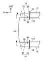
上下の重ね部34、36は、車両平面視において前端部が車両幅方向外側で後端部が車両幅方向内側となるように斜め方向に配置されることで、図4及び図5に示されるように、クラッシュボックス16の衝撃吸収部18の図心50が衝撃吸収部18の長手方向(軸方向)に対して傾いて配置されている。
The upper and lower overlapping
また、図1に示されるように、クラッシュボックス16の衝撃吸収部18は左右対称であるため、上下の重ね部34、36は、車両平面視において左右一対の衝撃吸収部18の異なる対角方向に配置されている。本実施形態では、上下の重ね部34、36は、車両平面視において車両前方に開く略ハの字状に配置されている。これによって、図5に示されるように、衝撃吸収部18の図心50は、衝撃吸収部18の長手方向(軸方向)に対して車両前方に開く略ハの字状に傾いて配置されている。
Further, as shown in FIG. 1, since the
また、図2に示されるように、衝撃吸収部18は、縦壁部30B、32Bの稜線間の距離が長く、重ね部34、36でそれぞれ接合された上面部30A、32A及び下面部30C、32Cの稜線間の距離が、縦壁部30B、32Bよりも短い構成とされている。衝撃吸収部18の後端部には、縦壁部30B、32Bの縁部をそれぞれ外方に屈曲させた左右一対のフランジ部30D、32Dと、上面部30A及び下面部30Cの縁部をそれぞれ外方に屈曲させた上下一対のフランジ部30E(下側は図示省略)と、が形成されている。
As shown in FIG. 2, the
連結板20は、平面部20Aの周縁部を車両前方側に屈曲した屈曲部20Bを備えている。衝撃吸収部18の左右一対のフランジ部30D、32Dと上下一対のフランジ部30Eは、連結板20の平面部20Aに面接触状態で配置されており、フランジ部30D、32D及びフランジ部30Eの縁部と平面部20Aとが溶接(本実施形態ではアーク溶接)によって接合されている。
The connecting
クラッシュボックス16を構成する衝撃吸収部18は、断面の効率化等のために高張力鋼板の使用により薄板化、軽量化されている。また、連結板20の後面部は補強板14の前面部に面接触状態で配置されており(図1参照)、連結板20と補強板14とは締結具等により結合されている。
The
次に、本実施形態の作用並びに効果について説明する。 Next, the operation and effect of this embodiment will be described.
図2等に示されるように、クラッシュボックス16を構成する衝撃吸収部18は、車両幅方向外側に配置される断面略コ字状の第1パネル部材30と、車両幅方向内側に配置される断面略コ字状の第2パネル部材32との上下の重ね部34、36をスポット溶接40で接合することにより、車両前後方向に延在する閉断面が形成されている。図1及び図5に示されるように、クラッシュボックス16の衝撃吸収部18における第1パネル部材30と第2パネル部材32との上下の重ね部34、36を、車両平面視において左右一対のクラッシュボックス16(衝撃吸収部18)の異なる対角方向に配置することで、クラッシュボックス16(衝撃吸収部18)の図心50が衝撃吸収部18の長手方向(軸方向)に対して傾いて設定されている。本実施形態では、第1パネル部材30と第2パネル部材32との上下の重ね部34、36が、車両平面視において車両前方に開くハの字状に配置されており、クラッシュボックス16(衝撃吸収部18)の図心50が車両前方に開くハの字状に設定されている。
As shown in FIG. 2 and the like, the
ここで、車両10の前部に走行による左右モーメントが作用した際のクラッシュボックス16の状態について説明する。図6には、車両背面視にて車両10の右方向から荷重が作用した際の左右一対のクラッシュボックス16の図心50の状態が模式的に示されている。また、図7(A)には、車両10の横方向から荷重が作用した際の車両背面視にて右側のクラッシュボックス16の図心50の状態が模式的に示されており、図7(B)には、車両背面視にて左側のクラッシュボックス16の図心50の状態が模式的に示されている。
Here, the state of the
図7(A)、図7(B)では、車両前後方向に沿った線に対するクラッシュボックス16の図心50の傾きを角度θとしたとき、車両10の横方向からの入力Fを分解した状態が示されている。図6及び図7(B)に示されるように、車両背面視にて車両10の右方向から荷重が作用すると、車両背面視にて左側のクラッシュボックス16の図心50は仮想的に伸び、図6及び図7(A)に示されるように、車両背面視にて右側のクラッシュボックス16の図心50は仮想的に縮むため、左右一対のクラッシュボックス16で図心50の線長が異なる(線長差が生じる)ことになる。したがって、クラッシュボックス16(衝撃吸収部18)の横変形時の図心50の回転半径が異なり、車両背面視にて右側の図心50が突っ張るため、クラッシュボックス16が左右方向(横方向)に変形しにくい。このため、走行による左右モーメントが作用した際に、車両平面視において略長方形状の衝撃吸収部18が左右方向に変形することを抑制することができ、操縦安定性が向上する。
7A and 7B, the input F from the lateral direction of the
また、クラッシュボックス16の第1パネル部材30と第2パネル部材32との上下の重ね部34、36における溶接部が、車両平面視において車両前方に開くハの字状に配置されていることで(図1及び図5を参照)、図8に示されるように、例えば、車両背面視にて車両右側の斜め外方向から衝突体60と前面衝突したときに、衝突側のクラッシュボックス16(衝撃吸収部18)の図心50の方向で荷重を受けることができる。このため、クラッシュボックス16を曲げずに軸圧縮変形させることができる。
Further, the welded portions in the upper and lower overlapping
さらに、クラッシュボックス16の第1パネル部材30と第2パネル部材32との上下の重ね部34、36が、スポット溶接40により接合され、その溶接部間にクラッシュボックス16の長手方向(軸方向)と直交する段部42Aが設けられていることで、車両衝突時にクラッシュボックス16(衝撃吸収部18)を段部42Aで長手方向に変形させることができる。したがって、第1パネル部材30と第2パネル部材32との上下の重ね部34、36をクラッシュボックス16の稜線に対し斜めに設けても、クラッシュボックス16をより確実に軸圧壊させることができる。
Furthermore, the upper and lower overlapping
次に、図9〜図12を用いて、比較例に係る車両前部構造100について説明する。
Next, a
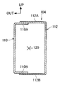
図9及び図10に示されるように、クラッシュボックス102を構成する衝撃吸収部104は、車両幅方向外側に配置される断面略コ字状の第1パネル部材110と、車両幅方向内側に配置される断面略コ字状の第2パネル部材112と、を備えている。第1パネル部材110は、車両幅方向内向きに開口しており、上面部110Aの内側縁部及び下面部110Bの内側縁部は車両前後方向に沿って配置されている。第2パネル部材112は、車両幅方向外向きに開口しており、上面部112Aの外側縁部及び下面部112Bの外側縁部は車両前後方向に沿って配置されている。
As shown in FIG. 9 and FIG. 10, the
第2パネル部材112の上面部112Aの車両下方に第1パネル部材110の上面部110Aが重ね合わされてスポット溶接により接合されると共に、第2パネル部材112の下面部112Bの車両上方に第1パネル部材110の下面部110Bが重ね合わされてスポット溶接により接合されることで、閉断面が形成されている。
The
図10に示されるように、衝撃吸収部104は、第1パネル部材110と第2パネル部材112の断面形状が車両前後方向でほぼ同一に形成されており、第1パネル部材110と第2パネル部材112のスポット溶接(図示省略)による接合部が衝撃吸収部104の稜線に沿って配置されている。図10及び図11に示されるように、このクラッシュボックス102では、衝撃吸収部104の図心120が衝撃吸収部104の長手方向(軸方向)に沿って配置されている。すなわち、車両平面視において左右一対の衝撃吸収部104の図心120は、衝撃吸収部104の長手方向に沿ってほぼ平行に配置されており、左右の図心120の線長が等しい。
As shown in FIG. 10, in the
このような車両前部構造100では、図11及び図12に示されるように、走行による左右モーメントが作用した際に、左右一対の衝撃吸収部104で図心120の線長が等しいため、横変形時の図心120の回転半径が等しく、クラッシュボックス102が左右方向(横方向)に変形しやすい。このため、車両走行時にフロントサイドメンバ12が左右方向に振られたとき、フロントバンパリインフォースメント24、クラッシュボックス102も合わせて左右方向に振られる可能性がある。
In such a
これに対して、本実施形態では、車両10の走行による左右モーメントが作用した際に、左右一対の衝撃吸収部18で図心50の線長差が生じ、衝撃吸収部18が左右方向に変形しにくい。このため、クラッシュボックス16が左右方向に変形することを抑制することができ、操縦安定性が向上する。
On the other hand, in the present embodiment, when a left / right moment due to traveling of the
なお、本実施形態では、車両平面視において左右一対のクラッシュボックス16の図心50が車両前方に開く略ハの字状に設定されているが、これに限定されず、車両平面視において左右一対のクラッシュボックス16の図心50が車両前方に狭まる略ハの字状(逆ハの字状)に設定してもよい。
In the present embodiment, the
また、本実施形態では、スポット溶接40による溶接部間の段部42Aは、第1パネル部材30と第2パネル部材32の両方に設けられているが、これに限定されず、第1パネル部材30及び第2パネル部材32のいずれか一方に設ける構成でもよい。また、スポット溶接40による溶接部間の段部42Aは、衝撃吸収部18の上面と下面の両方に設けられているが、これに限定されず、衝撃吸収部18の上面及び下面のいずれか一方に設ける構成でもよい。また、段部42Aは、スポット溶接40による溶接部間の少なくとも一部に設けられていればよい。
Further, in the present embodiment, the stepped
また、本実施形態では、第2パネル部材32の上面部32A及び第1パネル部材30の上面部30A、第2パネル部材32の下面部32C及び第1パネル部材30の下面部30Cを車両平面視にて対角方向にカットした形状であるが、このような形状に限らず、第2パネル部材32の上面部及び第1パネル部材30の上面部、第2パネル部材32の下面部及び第1パネル部材30の下面部の溶接点が対角方向にあればよい。
In the present embodiment, the
また、本実施形態では、第2パネル部材32の上面部32Aの車両下方に第1パネル部材30の上面部30Aを重ね合わせて接合し、第2パネル部材32の下面部32Cの車両上方に第1パネル部材30の下面部30Cを重ね合わせて接合したが、これに限定されず、上面部32Aと上面部30Aの重ね部、下面部32Cと下面部30Cの重ね部の上下関係を変更してもよい。
In the present embodiment, the
10 車両
12 フロントサイドメンバ(サイドメンバ)
16 クラッシュボックス
18 衝撃吸収部
24 フロントバンパリインフォースメント(バンパリインフォース)
30 第1パネル部材
30A 上面部
30C 下面部
32 第2パネル部材
32A 上面部
32C 下面部
34 重ね部
36 重ね部
40 スポット溶接(溶接部)
42 突出部
42A 段部
50 図心
10
16
30
42
Claims (3)
前記サイドメンバに対して車両前方側に設けられ、車両幅方向に沿って配設されるバンパリインフォースと、
前記サイドメンバと前記バンパリインフォースとの間に設けられ、車両幅方向外側に配置される断面略コ字状の第1パネル部材と、車両幅方向内側に配置される断面略コ字状の第2パネル部材とを備えると共に、前記第1パネル部材と前記第2パネル部材との両端部同士を車両上下面に設けられた重ね部で接合して車両前後方向に延在する閉断面が形成される左右一対のクラッシュボックスと、
を有すると共に、
前記重ね部における接合部が、車両平面視において左右一対の前記クラッシュボックスの異なる対角方向に配置されている車両前部構造。 A pair of left and right side members extending in the vehicle front-rear direction at the front of the vehicle;
Bumper reinforcement provided on the vehicle front side with respect to the side member and disposed along the vehicle width direction;
A first panel member that is provided between the side member and the bumper reinforcement and is disposed on the outer side in the vehicle width direction, and a second panel having a substantially U-shaped cross section that is disposed on the inner side in the vehicle width direction. And a closed section that extends in the vehicle front-rear direction is formed by joining both ends of the first panel member and the second panel member with overlapping portions provided on the upper and lower surfaces of the vehicle. A pair of left and right crash boxes,
And having
The vehicle front part structure in which the junction part in the said overlap part is arrange | positioned in the diagonal direction from which a pair of left and right said crush boxes differ in planar view of a vehicle.
Priority Applications (1)
| Application Number | Priority Date | Filing Date | Title |
|---|---|---|---|
| JP2011022000A JP2012162108A (en) | 2011-02-03 | 2011-02-03 | Vehicle front structure |
Applications Claiming Priority (1)
| Application Number | Priority Date | Filing Date | Title |
|---|---|---|---|
| JP2011022000A JP2012162108A (en) | 2011-02-03 | 2011-02-03 | Vehicle front structure |
Publications (1)
| Publication Number | Publication Date |
|---|---|
| JP2012162108A true JP2012162108A (en) | 2012-08-30 |
Family
ID=46841978
Family Applications (1)
| Application Number | Title | Priority Date | Filing Date |
|---|---|---|---|
| JP2011022000A Pending JP2012162108A (en) | 2011-02-03 | 2011-02-03 | Vehicle front structure |
Country Status (1)
| Country | Link |
|---|---|
| JP (1) | JP2012162108A (en) |
Cited By (5)
| Publication number | Priority date | Publication date | Assignee | Title |
|---|---|---|---|---|
| WO2014083926A1 (en) * | 2012-11-30 | 2014-06-05 | アイシン精機株式会社 | Crush box |
| WO2015053075A1 (en) * | 2013-10-09 | 2015-04-16 | 新日鐵住金株式会社 | Crush box and method for manufacturing same |
| JP2015189317A (en) * | 2014-03-28 | 2015-11-02 | 富士重工業株式会社 | shock absorbing structure |
| KR20160125191A (en) * | 2015-04-21 | 2016-10-31 | 주식회사 성우하이텍 | Bumper stay unit for vehicle |
| KR101689581B1 (en) * | 2015-12-01 | 2016-12-26 | 주식회사 성우하이텍 | Bumper stay unit for vehicles |
Citations (4)
| Publication number | Priority date | Publication date | Assignee | Title |
|---|---|---|---|---|
| JPH08324454A (en) * | 1995-03-28 | 1996-12-10 | Mazda Motor Corp | Frame structure of automobile body |
| JP2008120324A (en) * | 2006-11-15 | 2008-05-29 | Toyotomi Kiko Co Ltd | Energy absorption member for vehicles |
| JP2009029409A (en) * | 2007-07-28 | 2009-02-12 | Dr Ing Hcf Porsche Ag | Crash equipment |
| JP2010125884A (en) * | 2008-11-25 | 2010-06-10 | Honda Motor Co Ltd | Front vehicle body structure |
-
2011
- 2011-02-03 JP JP2011022000A patent/JP2012162108A/en active Pending
Patent Citations (4)
| Publication number | Priority date | Publication date | Assignee | Title |
|---|---|---|---|---|
| JPH08324454A (en) * | 1995-03-28 | 1996-12-10 | Mazda Motor Corp | Frame structure of automobile body |
| JP2008120324A (en) * | 2006-11-15 | 2008-05-29 | Toyotomi Kiko Co Ltd | Energy absorption member for vehicles |
| JP2009029409A (en) * | 2007-07-28 | 2009-02-12 | Dr Ing Hcf Porsche Ag | Crash equipment |
| JP2010125884A (en) * | 2008-11-25 | 2010-06-10 | Honda Motor Co Ltd | Front vehicle body structure |
Cited By (9)
| Publication number | Priority date | Publication date | Assignee | Title |
|---|---|---|---|---|
| WO2014083926A1 (en) * | 2012-11-30 | 2014-06-05 | アイシン精機株式会社 | Crush box |
| WO2015053075A1 (en) * | 2013-10-09 | 2015-04-16 | 新日鐵住金株式会社 | Crush box and method for manufacturing same |
| JPWO2015053075A1 (en) * | 2013-10-09 | 2017-03-09 | 新日鐵住金株式会社 | Crash box and manufacturing method thereof |
| TWI583579B (en) * | 2013-10-09 | 2017-05-21 | Nippon Steel & Sumitomo Metal Corp | Collision box and manufacturing method thereof |
| US10363892B2 (en) | 2013-10-09 | 2019-07-30 | Nippon Steel Corporation | Crash box and method for producing the same |
| JP2015189317A (en) * | 2014-03-28 | 2015-11-02 | 富士重工業株式会社 | shock absorbing structure |
| KR20160125191A (en) * | 2015-04-21 | 2016-10-31 | 주식회사 성우하이텍 | Bumper stay unit for vehicle |
| KR101689574B1 (en) | 2015-04-21 | 2016-12-26 | 주식회사 성우하이텍 | Bumper stay unit for vehicle |
| KR101689581B1 (en) * | 2015-12-01 | 2016-12-26 | 주식회사 성우하이텍 | Bumper stay unit for vehicles |
Similar Documents
| Publication | Publication Date | Title |
|---|---|---|
| JP5920486B2 (en) | Vehicle end structure | |
| JP6236046B2 (en) | Body structure | |
| JP5487236B2 (en) | Car body side structure | |
| CN109923002B (en) | Impact absorbing structure for vehicle | |
| CN106585542A (en) | Vehicle body structure with impact absorbing part | |
| JP2014108755A (en) | Vehicle body front part structure | |
| JP6577978B2 (en) | Body structure | |
| JP6616000B2 (en) | Body frame structure | |
| JP2015209111A (en) | Vehicle front structure | |
| CN109906174B (en) | Shock Absorbing Structure for Vehicles | |
| WO2014156065A1 (en) | Bumper joining structure and crush box | |
| JP6265247B1 (en) | Vehicle shock absorption structure | |
| JP2023030757A (en) | Vehicle body lower part structure | |
| JP2012162108A (en) | Vehicle front structure | |
| JP2015147536A (en) | Vehicular bumper beam | |
| CN110884567B (en) | Front body structure of vehicle | |
| JP5857921B2 (en) | Front pillar structure | |
| CN116529148B (en) | Front longitudinal beam of vehicle | |
| JP5803819B2 (en) | Vehicle front structure | |
| JP5918092B2 (en) | Bumper beam for vehicles | |
| CN103223910B (en) | For the preposition energy absorption device of vehicle frame with have its vehicle frame, automobile | |
| JP2013147189A (en) | Vehicle body front structure | |
| JP6471768B2 (en) | Front body structure of the vehicle | |
| JP6642480B2 (en) | Side member tip structure | |
| JP2015189406A (en) | Bumper device of vehicle |
Legal Events
| Date | Code | Title | Description |
|---|---|---|---|
| A621 | Written request for application examination |
Free format text: JAPANESE INTERMEDIATE CODE: A621 Effective date: 20131017 |
|
| A977 | Report on retrieval |
Free format text: JAPANESE INTERMEDIATE CODE: A971007 Effective date: 20140709 |
|
| A131 | Notification of reasons for refusal |
Free format text: JAPANESE INTERMEDIATE CODE: A131 Effective date: 20140722 |
|
| A521 | Written amendment |
Free format text: JAPANESE INTERMEDIATE CODE: A523 Effective date: 20140917 |
|
| A02 | Decision of refusal |
Free format text: JAPANESE INTERMEDIATE CODE: A02 Effective date: 20150303 |