JP2012164094A - Gas alarm and heater voltage setting method of gas sensor in gas alarm - Google Patents
Gas alarm and heater voltage setting method of gas sensor in gas alarm Download PDFInfo
- Publication number
- JP2012164094A JP2012164094A JP2011023322A JP2011023322A JP2012164094A JP 2012164094 A JP2012164094 A JP 2012164094A JP 2011023322 A JP2011023322 A JP 2011023322A JP 2011023322 A JP2011023322 A JP 2011023322A JP 2012164094 A JP2012164094 A JP 2012164094A
- Authority
- JP
- Japan
- Prior art keywords
- heater
- voltage
- gas
- value
- circuit unit
- Prior art date
- Legal status (The legal status is an assumption and is not a legal conclusion. Google has not performed a legal analysis and makes no representation as to the accuracy of the status listed.)
- Granted
Links
Images

Landscapes
- Investigating Or Analyzing Materials By The Use Of Fluid Adsorption Or Reactions (AREA)
- Emergency Alarm Devices (AREA)
Abstract
【課題】ガス警報器におけるセンサ電圧調整技術に関し、ヒータ電圧の初期設定の工数を削減する。
【解決手段】ガス警報器の初期設定時に以下の制御が実行される。まず、制御回路部104は、定電圧回路部110を介してガスセンサ101内のヒータ抵抗103にヒータ電圧を印加する。制御回路部104は、AD変換入力端子AD1とAD2を介して、ヒータ抵抗両端の電圧値と電流値を算出し、それらの積としてヒータ電力を算出する。制御回路部104は、ヒータ電力が所定設定値になるようにヒータ電圧を制御する。
【選択図】図1The present invention relates to a sensor voltage adjustment technique in a gas alarm device, and reduces the man-hour for initial setting of a heater voltage.
The following control is executed at the time of initial setting of a gas alarm. First, the control circuit unit 104 applies a heater voltage to the heater resistor 103 in the gas sensor 101 via the constant voltage circuit unit 110. The control circuit unit 104 calculates the voltage value and the current value at both ends of the heater resistor via the AD conversion input terminals AD1 and AD2, and calculates the heater power as the product of them. The control circuit unit 104 controls the heater voltage so that the heater power becomes a predetermined set value.
[Selection] Figure 1
Description
本発明は、ガス警報器におけるガスセンサのヒータ電圧の調整技術に関する。 The present invention relates to a technology for adjusting a heater voltage of a gas sensor in a gas alarm device.
ガス警報器においては、都市ガスやLPガスなどの検知対象ガスを検知するためにガスセンサが用いられている。ガスセンサは、ガスを検知するために、ヒータ抵抗に電圧を印加してヒータ温度をたとえば400℃など所定温度に加熱して使用される。そして、検知ガスとの反応により変化するセンサ抵抗の変化を測定することにより、ガス検知を行っている。 In the gas alarm device, a gas sensor is used to detect a detection target gas such as city gas or LP gas. The gas sensor is used by applying a voltage to the heater resistance and heating the heater temperature to a predetermined temperature such as 400 ° C. in order to detect gas. And gas detection is performed by measuring the change of the sensor resistance which changes with reaction with detection gas.
ヒータ温度は、ヒータ部に注入する電力量(電圧×電流)によって制御することができる。ヒータ温度が所定の値よりも低い場合は、検知ガスに対するセンサの感度が不十分だったり、検知ガス以外のガスに対して高感度化したりする。ヒータ温度が所定の値よりも高い場合は、ガスに対する感度変化の他にセンサ自体を故障させてしまう恐れもある。そのため、ヒータ温度を常に一定に保つ必要がある。 The heater temperature can be controlled by the amount of electric power (voltage × current) injected into the heater section. When the heater temperature is lower than a predetermined value, the sensitivity of the sensor with respect to the detection gas is insufficient, or the sensitivity is increased with respect to gases other than the detection gas. If the heater temperature is higher than a predetermined value, the sensor itself may be damaged in addition to a change in sensitivity to gas. Therefore, it is necessary to keep the heater temperature constant.
また、ヒータは、金属系の材料で製造されるが、製造上のバラツキなどによりヒータの抵抗値を一定に生産することが困難であり、全てのセンサに同じヒータ電圧を印加してもヒータに流れる電流が一定とならないため、ヒータ温度が一定とならない問題がある。 In addition, although the heater is manufactured from a metal-based material, it is difficult to produce a constant heater resistance value due to manufacturing variations, etc., and even if the same heater voltage is applied to all sensors, Since the flowing current is not constant, there is a problem that the heater temperature is not constant.
このため、従来は、センサ個々のヒータ抵抗値のバラツキに起因するヒータ温度のバラツキを補正し、ヒータ温度を一定に保つ為に、ガスセンサのヒータ電圧を1台毎に調整し警報器本体に記憶させる必要があった。 For this reason, conventionally, in order to correct the heater temperature variation caused by variations in the heater resistance value of each sensor and to keep the heater temperature constant, the heater voltage of each gas sensor is adjusted and stored in the main body of the alarm device. It was necessary to let them.
図3は、従来技術におけるヒータ電圧の制御処理を示すフローチャートである。
まず、通常使用モードか、ヒータを調整するモードかを判定する(図3のS1)。ガス警報器は、通常のガスもれを検知するモードとは別に、警報器の各種設定を行うためのモードを備えている。
FIG. 3 is a flowchart showing a heater voltage control process in the prior art.
First, it is determined whether the mode is the normal use mode or the mode for adjusting the heater (S1 in FIG. 3). The gas alarm device has a mode for performing various settings of the alarm device in addition to a mode for detecting a normal gas leak.
そして、ヒータ調整モードの場合(図3のS1の判定がYesの場合)は、ガスセンサのヒータ部へ印加するヒータ電圧を外部から設定できるようにしている。
まず、目標値のヒータ温度になるようなヒータ電圧設定値を、ガス警報器の外部に接続された調整信号設定器より、ガス警報器内部の調整信号入力部を介して制御回路部(マイコン)に設定する(図3のS2)。
In the heater adjustment mode (when the determination of S1 in FIG. 3 is Yes), the heater voltage applied to the heater part of the gas sensor can be set from the outside.
First, a heater circuit voltage setting value that makes the target heater temperature reach the control circuit unit (microcomputer) from the adjustment signal setting unit connected to the outside of the gas alarm device via the adjustment signal input unit inside the gas alarm device (S2 in FIG. 3).
制御回路部は、設定されたヒータ電圧設定値に基づき、ヒータ電圧をガスセンサに印加する(図3のS3)。
このときのヒータ電圧を測定し(図3のS4)、測定されたヒータ電圧とヒータ電圧設定値が同一であるか否かを判定する(図3のS5)。
The control circuit unit applies the heater voltage to the gas sensor based on the set heater voltage setting value (S3 in FIG. 3).
The heater voltage at this time is measured (S4 in FIG. 3), and it is determined whether or not the measured heater voltage is the same as the heater voltage setting value (S5 in FIG. 3).
上記判定結果が不一致である場合は、図3のS2に戻りヒータ電圧変更して再度ヒータ電圧設定値を設定して、図3のS2からS5までの処理を、図3のS5で測定されたヒータ電圧とヒータ電圧設定値が一致するまで繰り返し実行する。 If the determination result is inconsistent, the process returns to S2 in FIG. 3 to change the heater voltage and set the heater voltage setting value again, and the processes from S2 to S5 in FIG. 3 are measured in S5 in FIG. The process is repeated until the heater voltage matches the heater voltage setting value.
図3のS5で測定されたヒータ電圧とヒータ電圧設定値の一致が判定されると(S5の判定がYes)、そのときのヒータ電圧設定値をEEPROMに書き込み、ヒータ電圧の制御処理を終了する(図3のS6)。 When it is determined that the heater voltage measured in S5 of FIG. 3 matches the heater voltage setting value (Yes in S5), the heater voltage setting value at that time is written to the EEPROM, and the heater voltage control process is terminated. (S6 in FIG. 3).
しかし、図3に示される制御方法では、図3のS4のヒータ電圧の測定と、S5の測定されたヒータ電圧とヒータ電圧設定値の一致判定は、従来、製造者が測定器を使って1台1台確認していた。このため、1台1台の初期設定の工数が多くかかってしまうという問題点を有していた。 However, in the control method shown in FIG. 3, the measurement of the heater voltage in S <b> 4 in FIG. 3 and the coincidence determination between the measured heater voltage and the heater voltage set value in S <b> 5 are conventionally performed by a manufacturer using a measuring instrument. I confirmed one unit. For this reason, there has been a problem that the number of man-hours for the initial setting of each unit increases.
また、ヒータ部の抵抗値のばらつきに応じて微妙な電力調整を製造者が手動でおこなっていたため、調整コストが増大するだけでなく調整ミスなどが発生する懸念もあった。
そこで、本発明の課題は、ヒータ電圧の初期設定の工数を削減し、調整時のミスがなく確実な調整が行えるようにすることにある。
Further, since the manufacturer manually performs delicate power adjustment according to the variation in the resistance value of the heater unit, there is a concern that not only the adjustment cost increases but also an adjustment error occurs.
Accordingly, an object of the present invention is to reduce the man-hours for initial setting of the heater voltage so that a reliable adjustment can be performed without any error during adjustment.
態様の一例では、ヒータ温度を一定に保つ必要があるガスセンサを備えるガス警報器として実現され、以下の構成を有する。
ヒータ電圧印加部は、ガスセンサ内のヒータ抵抗にヒータ電圧を印加する。
In an example, the embodiment is realized as a gas alarm including a gas sensor that needs to keep the heater temperature constant, and has the following configuration.
The heater voltage application unit applies a heater voltage to the heater resistance in the gas sensor.
ヒータ電力算出部は、ヒータ抵抗両端の電圧値と電流値を算出してヒータ電力を算出する。
ヒータ電圧可変部は、初期設定時に、ヒータ電力が所定設定値になるようにヒータ電圧を制御する。
The heater power calculation unit calculates the heater power by calculating the voltage value and the current value across the heater resistance.
The heater voltage variable unit controls the heater voltage so that the heater power becomes a predetermined set value at the time of initial setting.
算出されたヒータ電圧をヒータ電圧印加部よりヒータ抵抗に印加することにより、ヒータ温度を一定に保つ制御が実現でき、ガスもれの検出精度を向上させることができる。 By applying the calculated heater voltage to the heater resistance from the heater voltage application unit, it is possible to achieve control to keep the heater temperature constant, and to improve the accuracy of detection of gas leakage.
ガス警報器の1台毎にヒータ電圧を人手で調整する必要がなくなり、初期設定の工数の削減が可能となる。
また、人手による調整のミスがなくなり、確実な調整が行えるようになる。
It is no longer necessary to manually adjust the heater voltage for each gas alarm device, and the initial setting man-hours can be reduced.
In addition, there is no manual adjustment error, and reliable adjustment can be performed.
以下、本発明を実施するための形態について図面を参照しながら詳細に説明する。
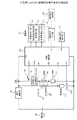
図1は、本発明によるガス警報器の実施形態の構成図である。
ガスセンサ101は、ガスを検出するためのセンサ抵抗102と、センサを加熱するためのヒータ抵抗103を備える。
Hereinafter, embodiments for carrying out the present invention will be described in detail with reference to the drawings.
FIG. 1 is a configuration diagram of an embodiment of a gas alarm device according to the present invention.
The
電池部105は3ボルトの電源を供給する。昇圧回路部106は、電池部105からの3ボルトの電圧を所定の定電圧にし、定電圧をガスセンサ101内のセンサ抵抗102と、負荷抵抗107と、SW2 108とからなるセンサ系回路に供給する。また、定電圧を、SW1 109と、定電圧回路部110と、ヒータ抵抗103と、シャント抵抗111とからなるヒータ系回路に供給する。さらに、定電圧を、制御回路部104の電源端子VDDに供給する。
The
制御回路部104は、ガス警報器全体の動作を制御するマイコンである。制御回路部104は、出力端子OUT1およびOUT3を介してトランジスタスイッチであるSW1 109およびSW2 108をオンする。この結果、ガスセンサ101内のセンサ抵抗102と、負荷抵抗107と、SW2 108とからなるセンサ系回路と、SW1 109と、定電圧回路部110と、ヒータ抵抗103と、シャント抵抗111とからなるヒータ系回路を動作させる。また、制御回路部104は、AD(アナログ−ディジタル)変換入力端子AD3を介して、ガスセンサ101のセンサ出力電圧を検出することにより、ガスもれ判定を行う。さらに、制御回路部104は、出力端子OUT2を介して定電圧回路部110にヒータ電圧値を供給する。OUT2は、DA(ディジタル−アナログ)出力やPWM(パルス幅変調)出力であり所定の電圧を定電圧回路部110に供給する。また、制御回路部104は、ガス警報器の初期設定時に、AD変換入力端子AD1,AD2からの制御出力に基づいてヒータ電力を自動測定しながら、測定されたヒータ電力が所定のヒータ電力設定値に一致するように定電圧回路部110に供給するヒータ電圧を徐々に可変させる。上述のヒータ電力設定値は、制御回路部104のマイコンソフトウエアに記載されている値や調整信号設定器118から調整信号入力部116および入力端子IN1を介して設定した値とする。
The control circuit unit 104 is a microcomputer that controls the operation of the entire gas alarm device. The control circuit unit 104 turns on
周囲温度検出部117は、本実施形態では詳細な説明を省略するが、AD変換入力端子AD4を介して周囲温度値を制御回路部104に入力し、制御回路部104に周囲温度に基づくヒータ電圧の制御を実施させる。 Although the detailed description is omitted in this embodiment, the ambient temperature detection unit 117 inputs an ambient temperature value to the control circuit unit 104 via the AD conversion input terminal AD4, and the heater voltage based on the ambient temperature is input to the control circuit unit 104. To implement the control.
警報部112は、警報音出力部113、警報表示部114、外部警報出力部115を備える。警報音出力部113は、警報音等の音を発する部分であり、例えばブザーやスピーカなどで構成される。警報音出力部113は、制御回路部104からの制御に基づいて、電子音や音声メッセージでガスもれ状態を知らせたりする。警報表示部114は、LED(発光ダイオード)で構成されており、監視時には、LEDを点灯、警報時にはLEDを点滅等、警報器の状態をLEDで知らせる。外部警報出力部115は、ガスメータや集中監視盤などの外部機器へ警報信号の出力を行う。
The
上述の構成において、制御回路部104と定電圧回路部110とかなる部分がヒータ電圧印加部を構成し、シャント抵抗111と制御回路部104とからなる部分がヒータ電力算出部を構成し、制御回路部104がさらにヒータ電圧可変部を構成する。
In the above-described configuration, a portion including the control circuit unit 104 and the constant
本実施形態では、20〜60秒のセンサ駆動周期で、100ms(ミリ秒)程度のセンサ駆動時間ずつ、ガスセンサ101を駆動する。具体的には、特には図示しないタイマによる制御に基づいてセンサ駆動周期でセンサ駆動時間ずつの割込みが発生する毎に、図1の制御回路部104が、以下の動作を実行する。すなわち、制御回路部104は、まず、SW1 109をオンすることにより、SW1 109と、定電圧回路部110と、ガスセンサ101内のヒータ抵抗103と、シャント抵抗111とからなるヒータ系回路を動作せる。このとき、定電圧回路部110には、後述する初期設定時に算出されEEPROMに保持されているヒータ電圧設定値が印加される。これにより、センサ駆動時間内にガスセンサ101が加熱される。続いて、制御回路部104は、SW2 108をオンすることにより、ガスセンサ101内のセンサ抵抗102と、負荷抵抗107と、SW2 108とからなるセンサ系回路を動作させる。これにより、センサ駆動時間内に、制御回路部104が、ガスもれ検知動作を実行する。
In the present embodiment, the
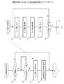
図2は、実施形態によるヒータ電圧調整処理のフローチャートである。ここで、図2(a)の、ヒータ駆動電圧を調整するための全体処理を示すフローチャートの処理が、ガス警報器の初期設定時に、制御回路部104によって実行される。 FIG. 2 is a flowchart of the heater voltage adjustment process according to the embodiment. Here, the process of the flowchart which shows the whole process for adjusting a heater drive voltage of Fig.2 (a) is performed by the control circuit part 104 at the time of the initialization of a gas alarm device.
まず、通常使用モードか、ヒータを調整するモードかを判定する(図2(a)のS1)。本実施形態のガス警報器は、従来技術と同様に、通常のモードとは別に、警報器の各種設定を行うためのモードを備えている。ガス警報器の初期設定時には、まず、ヒータ調整モードが設定される。 First, it is determined whether the mode is the normal use mode or the mode for adjusting the heater (S1 in FIG. 2A). The gas alarm device of the present embodiment includes a mode for performing various settings of the alarm device in addition to the normal mode, as in the conventional technology. When the gas alarm device is initially set, the heater adjustment mode is first set.
S1の判定の結果、ヒータ調整モードでない場合(図2(a)のS1の判定がNoの場合)には、ヒータ調整の処理は実行されない。
ガス警報器の初期設定時にヒータ調整モードが設定された場合(図2(a)のS1の判定がYesの場合)は、さらに、図1の制御回路部104の外部から、ヒータ調整コマンドが投入されるまで待機状態となる(図2(a)のS2の判定がNoの繰り返し)。
If the result of the determination in S1 is not the heater adjustment mode (when the determination in S1 in FIG. 2A is No), the heater adjustment process is not executed.
When the heater adjustment mode is set at the initial setting of the gas alarm (when the determination of S1 in FIG. 2A is Yes), a heater adjustment command is further input from the outside of the control circuit unit 104 in FIG. It will be in a standby state until it is performed (determination of S2 of Fig.2 (a) is No repetition).
ヒータ調整コマンドが投入されると(図2(a)のS2の判定がYes)、制御回路部104は、ヒータ電圧の自動設定処理を開始する(図2(a)のS3)。図2(b)は、このS3の処理の詳細を示すフローチャートである。 When the heater adjustment command is input (Yes in S2 in FIG. 2A), the control circuit unit 104 starts the heater voltage automatic setting process (S3 in FIG. 2A). FIG. 2B is a flowchart showing details of the process of S3.
まず、図1において、制御回路部104は、出力端子OUT2を介して定電圧回路部110に、ヒータ電圧値を供給する。この結果、定電圧回路部110は、制御回路部104から供給されたヒータ電圧値に対応するヒータ電圧を、ガスセンサ101内のヒータ抵抗103に印加する(図2(b)のS1)。この場合、最初に印加されるヒータ電圧は、ガスセンサ101が正常に動作すべき電圧よりも少し低い電圧となるように制御される。そして、2回目以降に図2(b)のS1が実行されるときには、電圧が徐々に高くなるように、定電圧回路部110に供給されるヒータ電圧値が調整される。
First, in FIG. 1, the control circuit unit 104 supplies a heater voltage value to the constant
次に、制御回路部104は、ガスセンサ101のヒータ抵抗103の両端に印加されるヒータ電圧値を読み込む。具体的には、AD変換入力端子AD1に入力される値からAD変換入力端子AD2に入力される値を減算して得られる値が、算出されたヒータ電圧値とされる(図2(b)のS2)。
Next, the control circuit unit 104 reads the heater voltage value applied to both ends of the
続いて、制御回路部104は、シャント抵抗111の電圧値を、AD変換入力端子AD2から読み込み、その電圧値を換算して電流値を算出する(図2(b)のS3)。なお、実際には、シャント抵抗111の両端の電圧がオペアンプで増幅されて測定される。また、シャント抵抗による電流検知は、たとえば電流を検知してガスセンサ101内のヒータ抵抗103の異常を検知し、故障警報を発報するような目的でも使用される。
Subsequently, the control circuit unit 104 reads the voltage value of the shunt resistor 111 from the AD conversion input terminal AD2, converts the voltage value, and calculates a current value (S3 in FIG. 2B). In practice, the voltage across the shunt resistor 111 is amplified by an operational amplifier and measured. The current detection by the shunt resistor is also used for the purpose of, for example, detecting a current to detect an abnormality of the
さらに、制御回路部104は、図2(b)のS2で算出されたヒータ電圧値と図2(b)のS3で算出された電流値の積を算出することにより、ヒータ電力を算出する(図2(b)のS4)。 Further, the control circuit unit 104 calculates heater power by calculating the product of the heater voltage value calculated in S2 of FIG. 2B and the current value calculated in S3 of FIG. S4 in FIG.
そして、制御回路部104は、図2(b)のS4で算出されたヒータ電力が、所定電力値(例えば30mW(ミリワット))であるか否かを判定する(図2(b)のS5)。この所定電力値は、図1の調整信号設定器118から調整信号入力部116および入力端子IN1を介して、制御回路部104内のメモリに保持されている。
Then, the control circuit unit 104 determines whether or not the heater power calculated in S4 of FIG. 2B is a predetermined power value (for example, 30 mW (milliwatt)) (S5 of FIG. 2B). . The predetermined power value is held in the memory in the control circuit unit 104 from the adjustment
この判定の結果、ヒータ電力が所定電力値と不一致であれば(図2(b)のS5の判定がNo)、出力端子OUT2を介して定電圧回路部110に供給されるヒータ電圧値が若干高くされて、図2(b)のS1の処理から繰り返される。
As a result of the determination, if the heater power does not match the predetermined power value (No in S5 in FIG. 2B), the heater voltage value supplied to the constant
以上の図2(b)のS1からS5までの一連の処理が、ヒータ電力が所定電力値と一致するまで繰り返し実行される。
ヒータ電力が所定電力値と一致すると(図2(b)のS5の判定がYes)、図2(a)のS3のヒータ電圧の自動設定処理を終了し、S3で自動設定されたヒータ電圧の設定値が制御回路部104内のメモリや外部のEEPROMに保存される(図2(a)のS4)。これにより、制御回路部104は、図3のフローチャートで示される制御処理を終了する。
The series of processes from S1 to S5 in FIG. 2B is repeatedly executed until the heater power matches the predetermined power value.
When the heater power matches the predetermined power value (Yes in S5 in FIG. 2B), the heater voltage automatic setting process in S3 in FIG. 2A is terminated, and the heater voltage automatically set in S3 is determined. The set value is stored in a memory in the control circuit unit 104 or an external EEPROM (S4 in FIG. 2A). Thereby, the control circuit unit 104 ends the control process shown in the flowchart of FIG.
以上のようにして、本実施形態では、ガス警報器の初期設定時に、ヒータ調整コマンドを実行するだけで、ヒータ電圧の設定値が自動で調整される。この結果、1台毎にヒータ電圧を人手で調整する必要がなくなり、初期設定の工数の削減が可能となる。 As described above, in the present embodiment, the heater voltage setting value is automatically adjusted by simply executing the heater adjustment command at the initial setting of the gas alarm device. As a result, it is not necessary to manually adjust the heater voltage for each unit, and the number of initial settings can be reduced.
101 ガスセンサ
102 センサ抵抗
103 ヒータ抵抗
104 制御回路部
105 電池部
106 昇圧回路部
107 負荷抵抗
108 SW2
109 SW1
110 定電圧回路部
111 シャント抵抗
112 警報部
113 警報音出力部
114 警報表示部
115 外部警報出力部
116 調整信号入力部
117 周囲温度検出部
118 調整信号設定器
DESCRIPTION OF
109 SW1
110 Constant Voltage Circuit Unit
Claims (4)
前記ガスセンサ内のヒータ抵抗にヒータ電圧を印加するヒータ電圧印加部と、
前記ヒータ抵抗両端の電圧値と電流値を算出してヒータ電力を算出するヒータ電力算出部と、
初期設定時に、前記ヒータ電力が所定設定値になるように前記ヒータ電圧を制御するヒータ電圧可変部と、
を備えることを特徴とするガス警報器。 In a gas alarm equipped with a gas sensor that needs to keep the heater temperature constant,
A heater voltage application unit for applying a heater voltage to the heater resistance in the gas sensor;
A heater power calculator that calculates a heater power by calculating a voltage value and a current value across the heater resistance; and
A heater voltage variable unit for controlling the heater voltage so that the heater power becomes a predetermined set value at the time of initial setting;
A gas alarm device comprising:
ことを特徴とする請求項1に記載のガス警報器。 The heater voltage application unit includes a constant voltage circuit unit.
The gas alarm device according to claim 1.
ことを特徴とする請求項1に記載のガス警報器。 The heater power calculation unit detects a voltage value and a current value at both ends of the heater resistor via a shunt resistor connected to the heater resistor, and calculates the heater power as a product of the voltage value and the current value.
The gas alarm device according to claim 1.
前記ガスセンサ内のヒータ抵抗にヒータ電圧を印加し、
前記ヒータ抵抗両端の電圧値と電流値を算出してヒータ電力を算出し、
前記ヒータ電力が所定設定値になるように前記ヒータ電圧を制御する、
ことを特徴とするガス警報器におけるガスセンサのヒータ電圧設定方法。
At the initial setting of a gas alarm equipped with a gas sensor that needs to keep the heater temperature constant,
Applying a heater voltage to the heater resistance in the gas sensor;
Calculate the heater power by calculating the voltage value and current value across the heater resistance,
Controlling the heater voltage so that the heater power becomes a predetermined set value;
A heater voltage setting method for a gas sensor in a gas alarm device.
Priority Applications (1)
| Application Number | Priority Date | Filing Date | Title |
|---|---|---|---|
| JP2011023322A JP5788188B2 (en) | 2011-02-04 | 2011-02-04 | Gas alarm, heater voltage setting method for gas sensor in gas alarm |
Applications Claiming Priority (1)
| Application Number | Priority Date | Filing Date | Title |
|---|---|---|---|
| JP2011023322A JP5788188B2 (en) | 2011-02-04 | 2011-02-04 | Gas alarm, heater voltage setting method for gas sensor in gas alarm |
Publications (2)
| Publication Number | Publication Date |
|---|---|
| JP2012164094A true JP2012164094A (en) | 2012-08-30 |
| JP5788188B2 JP5788188B2 (en) | 2015-09-30 |
Family
ID=46843431
Family Applications (1)
| Application Number | Title | Priority Date | Filing Date |
|---|---|---|---|
| JP2011023322A Active JP5788188B2 (en) | 2011-02-04 | 2011-02-04 | Gas alarm, heater voltage setting method for gas sensor in gas alarm |
Country Status (1)
| Country | Link |
|---|---|
| JP (1) | JP5788188B2 (en) |
Citations (8)
| Publication number | Priority date | Publication date | Assignee | Title |
|---|---|---|---|---|
| JPS63223552A (en) * | 1987-03-13 | 1988-09-19 | Osaka Gas Co Ltd | Semiconductor type gas sensor |
| JPH06331584A (en) * | 1993-05-21 | 1994-12-02 | Nohmi Bosai Ltd | Environmental sensor |
| JPH0712771A (en) * | 1993-06-29 | 1995-01-17 | Ricoh Seiki Co Ltd | Gas detector |
| JPH11248661A (en) * | 1998-03-04 | 1999-09-17 | Fuji Electric Co Ltd | Gas detection alarm |
| JP2006118490A (en) * | 2004-09-27 | 2006-05-11 | Toyota Motor Corp | Sensor abnormality detection device |
| JP2008046007A (en) * | 2006-08-17 | 2008-02-28 | Fuji Electric Fa Components & Systems Co Ltd | Anomaly detection method for thin film gas sensor |
| JP2009210341A (en) * | 2008-03-03 | 2009-09-17 | Osaka Gas Co Ltd | Gas detection device |
| JP2010127487A (en) * | 2008-11-25 | 2010-06-10 | Ngk Spark Plug Co Ltd | Heater energization control apparatus |
-
2011
- 2011-02-04 JP JP2011023322A patent/JP5788188B2/en active Active
Patent Citations (8)
| Publication number | Priority date | Publication date | Assignee | Title |
|---|---|---|---|---|
| JPS63223552A (en) * | 1987-03-13 | 1988-09-19 | Osaka Gas Co Ltd | Semiconductor type gas sensor |
| JPH06331584A (en) * | 1993-05-21 | 1994-12-02 | Nohmi Bosai Ltd | Environmental sensor |
| JPH0712771A (en) * | 1993-06-29 | 1995-01-17 | Ricoh Seiki Co Ltd | Gas detector |
| JPH11248661A (en) * | 1998-03-04 | 1999-09-17 | Fuji Electric Co Ltd | Gas detection alarm |
| JP2006118490A (en) * | 2004-09-27 | 2006-05-11 | Toyota Motor Corp | Sensor abnormality detection device |
| JP2008046007A (en) * | 2006-08-17 | 2008-02-28 | Fuji Electric Fa Components & Systems Co Ltd | Anomaly detection method for thin film gas sensor |
| JP2009210341A (en) * | 2008-03-03 | 2009-09-17 | Osaka Gas Co Ltd | Gas detection device |
| JP2010127487A (en) * | 2008-11-25 | 2010-06-10 | Ngk Spark Plug Co Ltd | Heater energization control apparatus |
Also Published As
| Publication number | Publication date |
|---|---|
| JP5788188B2 (en) | 2015-09-30 |
Similar Documents
| Publication | Publication Date | Title |
|---|---|---|
| TW201246138A (en) | Battery-powered gas alarm and control device thereof | |
| JP4624511B2 (en) | Controller for linear oxygen sensor | |
| JP6446894B2 (en) | Gas alarm and its control device | |
| JP5788188B2 (en) | Gas alarm, heater voltage setting method for gas sensor in gas alarm | |
| JP5755899B2 (en) | Gas alarm device and heater power control method for gas sensor in gas alarm device | |
| JP7127591B2 (en) | TEMPERATURE CONTROL DEVICE, TEMPERATURE CONTROL METHOD, AND PROGRAM | |
| JP5111180B2 (en) | Thermal flow meter | |
| JP2017037835A (en) | Method to ensure the operation of the heating device | |
| JP5755898B2 (en) | Gas alarm, gas sensor heater temperature control method in gas alarm | |
| JP6229383B2 (en) | Gas alarm | |
| JP3700379B2 (en) | Gas detection alarm | |
| WO2019244475A1 (en) | Gas detection device and gas detection method | |
| JP5608761B2 (en) | Battery-powered alarm | |
| JP2009295094A (en) | Gas leak alarm | |
| JP3700378B2 (en) | Gas detection alarm | |
| JP5184221B2 (en) | Gas leak alarm | |
| JP5546848B2 (en) | Gas leak alarm | |
| JPH0510571B2 (en) | ||
| JP2015158790A (en) | alarm | |
| JPH08249565A (en) | Gas leak alarm | |
| JP2000155879A (en) | Fire alarm, inspection method and recording medium | |
| JPH04284514A (en) | Alarm level setting device for control object | |
| JP4353999B1 (en) | Gas sensor device | |
| JP5185700B2 (en) | Gas leak alarm | |
| KR100705461B1 (en) | Artificial intelligence gas alarm and alarm method |
Legal Events
| Date | Code | Title | Description |
|---|---|---|---|
| A621 | Written request for application examination |
Free format text: JAPANESE INTERMEDIATE CODE: A621 Effective date: 20130913 |
|
| A977 | Report on retrieval |
Free format text: JAPANESE INTERMEDIATE CODE: A971007 Effective date: 20140305 |
|
| A131 | Notification of reasons for refusal |
Free format text: JAPANESE INTERMEDIATE CODE: A131 Effective date: 20140311 |
|
| A521 | Request for written amendment filed |
Free format text: JAPANESE INTERMEDIATE CODE: A523 Effective date: 20140509 |
|
| A131 | Notification of reasons for refusal |
Free format text: JAPANESE INTERMEDIATE CODE: A131 Effective date: 20141125 |
|
| A521 | Request for written amendment filed |
Free format text: JAPANESE INTERMEDIATE CODE: A523 Effective date: 20150126 |
|
| TRDD | Decision of grant or rejection written | ||
| A01 | Written decision to grant a patent or to grant a registration (utility model) |
Free format text: JAPANESE INTERMEDIATE CODE: A01 Effective date: 20150707 |
|
| A61 | First payment of annual fees (during grant procedure) |
Free format text: JAPANESE INTERMEDIATE CODE: A61 Effective date: 20150729 |
|
| R150 | Certificate of patent or registration of utility model |
Ref document number: 5788188 Country of ref document: JP Free format text: JAPANESE INTERMEDIATE CODE: R150 |
|
| R250 | Receipt of annual fees |
Free format text: JAPANESE INTERMEDIATE CODE: R250 |
|
| R250 | Receipt of annual fees |
Free format text: JAPANESE INTERMEDIATE CODE: R250 |
|
| R250 | Receipt of annual fees |
Free format text: JAPANESE INTERMEDIATE CODE: R250 |
|
| R250 | Receipt of annual fees |
Free format text: JAPANESE INTERMEDIATE CODE: R250 |
|
| R250 | Receipt of annual fees |
Free format text: JAPANESE INTERMEDIATE CODE: R250 |
|
| R250 | Receipt of annual fees |
Free format text: JAPANESE INTERMEDIATE CODE: R250 |
|
| R250 | Receipt of annual fees |
Free format text: JAPANESE INTERMEDIATE CODE: R250 |
|
| R250 | Receipt of annual fees |
Free format text: JAPANESE INTERMEDIATE CODE: R250 |
|
| S111 | Request for change of ownership or part of ownership |
Free format text: JAPANESE INTERMEDIATE CODE: R313117 |
|
| R350 | Written notification of registration of transfer |
Free format text: JAPANESE INTERMEDIATE CODE: R350 |