JP2012166865A - Step for escalator and escalator display system - Google Patents
Step for escalator and escalator display system Download PDFInfo
- Publication number
- JP2012166865A JP2012166865A JP2011026846A JP2011026846A JP2012166865A JP 2012166865 A JP2012166865 A JP 2012166865A JP 2011026846 A JP2011026846 A JP 2011026846A JP 2011026846 A JP2011026846 A JP 2011026846A JP 2012166865 A JP2012166865 A JP 2012166865A
- Authority
- JP
- Japan
- Prior art keywords
- escalator
- display
- riser
- tread
- generator
- Prior art date
- Legal status (The legal status is an assumption and is not a legal conclusion. Google has not performed a legal analysis and makes no representation as to the accuracy of the status listed.)
- Withdrawn
Links
- 230000007246 mechanism Effects 0.000 claims description 19
- 238000001514 detection method Methods 0.000 claims description 10
- 230000001174 ascending effect Effects 0.000 claims description 2
- 230000003028 elevating effect Effects 0.000 abstract 1
- 230000006870 function Effects 0.000 description 17
- 239000011159 matrix material Substances 0.000 description 5
- 230000004907 flux Effects 0.000 description 3
- 239000011347 resin Substances 0.000 description 3
- 229920005989 resin Polymers 0.000 description 3
- 230000005540 biological transmission Effects 0.000 description 2
- 230000004397 blinking Effects 0.000 description 2
- 230000005611 electricity Effects 0.000 description 2
- 238000010248 power generation Methods 0.000 description 2
- 230000003014 reinforcing effect Effects 0.000 description 2
- 230000001133 acceleration Effects 0.000 description 1
- 230000003321 amplification Effects 0.000 description 1
- 239000003990 capacitor Substances 0.000 description 1
- 230000008859 change Effects 0.000 description 1
- 238000006243 chemical reaction Methods 0.000 description 1
- 238000010586 diagram Methods 0.000 description 1
- 230000000694 effects Effects 0.000 description 1
- 239000000835 fiber Substances 0.000 description 1
- 239000004973 liquid crystal related substance Substances 0.000 description 1
- 239000000463 material Substances 0.000 description 1
- 239000002184 metal Substances 0.000 description 1
- 238000000034 method Methods 0.000 description 1
- 238000003199 nucleic acid amplification method Methods 0.000 description 1
- 230000009467 reduction Effects 0.000 description 1
- 230000000007 visual effect Effects 0.000 description 1
Images


Landscapes
- Escalators And Moving Walkways (AREA)
Abstract
Description
本発明は、エスカレータ用ステップ及びエスカレータ表示システムに係り、特に、表示機能を有するエスカレータ用ステップ及びそのステップを用いるエスカレータ表示システムに関する。 The present invention relates to an escalator step and an escalator display system, and more particularly to an escalator step having a display function and an escalator display system using the step.
エスカレータは、乗客が乗る踏板と蹴上げに相当するライザとを含む複数のステップを無端状に接続して、予め定めた昇降傾斜角度で、下層階乗場と上層階乗場の間に配置される昇降装置である。この踏板およびライザは、人目に触れるものであるので、これらを広告媒体等として用いようとする考えがある。 The escalator is an elevator that is connected between a lower floor landing and an upper floor landing at a predetermined elevation inclination angle by connecting a plurality of steps including a step board on which a passenger rides and a riser corresponding to a kick-up in an endless manner. It is. Since the tread board and the riser are in contact with human eyes, there is an idea of using them as an advertising medium or the like.
例えば特許文献1には、エスカレータのステップにおいて、踏板の両側下部に設けられて踏板を下方から支持するブラケットの間に渡って開口部が形成された金属製補強板を設け、その開口を覆うように透光性を有する繊維強化樹脂製のライザを固定することが開示されている。そして、ライザの裏面に任意の図柄、文字等を印刷し、これをエスカレータ内部に設けた照明器具で照明することで、意匠性を向上させることが述べられている。 For example, in Patent Document 1, a metal reinforcing plate having openings formed between brackets that are provided at lower portions on both sides of a tread board and support the tread board from below is provided in an escalator step so as to cover the opening. It is disclosed to fix a riser made of fiber reinforced resin having translucency. And it is described that arbitrary design, characters, etc. are printed on the back surface of the riser, and this is illuminated with a lighting fixture provided inside the escalator to improve the design.
また、特許文献2には、エスカレータの踏段照明装置として、踏板上面に太陽電池と発光ダイオードを埋め込むことが開示されている。これによって、太陽光あるいは電灯で太陽電池が発電し、これを蓄電池に蓄電しスイッチを介して発光ダイオードを発光させ踏段を照明することが述べられている。 Patent Document 2 discloses that a solar cell and a light-emitting diode are embedded on the top surface of a tread board as a step lighting device for an escalator. Accordingly, it is described that a solar cell generates electricity with sunlight or an electric lamp, stores this in a storage battery, and emits a light emitting diode through a switch to illuminate a step.
また、非特許文献1には、LEDを使用したエスカレータ乗場安全装置として、ステップチェーン等のエスカレータが動くと動作する機器に小型の発電機を取り付け、この発電を利用して、乗場付近に設けた緑色のLED、踏段への乗口付近に設けた赤色のLEDを発光させることが述べられている。 In addition, in Non-Patent Document 1, as an escalator landing safety device using an LED, a small generator is attached to a device that operates when an escalator such as a step chain moves, and is provided near the landing using this power generation. It is described that a green LED and a red LED provided near the entrance to the step are made to emit light.
エスカレータのステップを広告媒体等に用いることができる表示機能を付与するには、乗客が乗る踏板の強度、ステップの表示部に供給する電源をどのように確保するかが課題である。また、ステップは無端状に接続され、複数のステップのうち、約半数は床下に隠れて人目に触れないので、不必要な表示を行わない工夫等も必要である。 In order to provide a display function that can use an escalator step for an advertising medium or the like, how to secure the strength of the tread board on which the passenger rides and the power supplied to the display unit of the step is a problem. In addition, since the steps are connected endlessly, and about half of the plurality of steps are hidden under the floor and cannot be seen by the human eye, it is necessary to devise a technique for preventing unnecessary display.
本発明の目的は、表示機能を付与するために特別な外部電源を必要としないエスカレータ用ステップ及びそのステップを用いるエスカレータ表示システムを提供することである。また、他の目的は、エスカレータ全体としての効果的な表示を可能とするエスカレータ表示システムを提供することである。 An object of the present invention is to provide an escalator step that does not require a special external power source for providing a display function, and an escalator display system using the step. Another object is to provide an escalator display system that enables effective display of the escalator as a whole.
本発明に係るエスカレータ用ステップは、エスカレータの乗客が乗る踏板と、踏板の下部に配置されて踏板を下方から支持するフレームと、フレームに配置され、エスカレータの傾斜部での蹴上げに相当するライザと、フレームのライザ側下部に回動可能に設けられ、エスカレータが昇降動作すると共に回転する一対のステップローラと、ステップローラの回転速度を増速する増速機構と、増速機構に接続され、回転速度に応じた発電電力を出力する発電機と、発電電力を蓄電する蓄電装置と、踏板またはライザに設けられ、蓄電装置からの電力によって表示を行う表示部と、を備えることを特徴とする。 The escalator step according to the present invention includes a step board on which an escalator passenger rides, a frame that is disposed at a lower part of the tread board and supports the tread from below, a riser that is disposed on the frame and corresponds to kicking at an inclined part of the escalator, A pair of step rollers which are rotatably provided at the lower part of the riser side of the frame and rotate while the escalator moves up and down, a speed increasing mechanism for increasing the rotation speed of the step rollers, and a speed increasing mechanism for rotation. It is characterized by comprising a generator that outputs generated power according to speed, a power storage device that stores the generated power, and a display unit that is provided on a tread board or a riser and performs display using power from the power storage device.
また、本発明に係るエスカレータ用ステップにおいて、表示部は、踏板またはライザの背後に設けられ、表示部が設けられる踏板またはライザは、表示部からの光を通す透光孔部を有することが好ましい。 Further, in the escalator step according to the present invention, it is preferable that the display unit is provided behind the step board or the riser, and the step board or the riser on which the display unit is provided has a light transmitting hole portion through which light from the display unit passes. .
また、本発明に係るエスカレータ用ステップにおいて、踏板周辺の明るさまたはライザ周辺の明るさを検知する検知部と、検知部の検知結果に応じ、表示部に対する表示制御を行う表示制御回路と、を備えることが好ましい。 Further, in the escalator step according to the present invention, a detection unit that detects the brightness around the tread board or the brightness around the riser, and a display control circuit that performs display control on the display unit according to the detection result of the detection unit, It is preferable to provide.
また、本発明に係るエスカレータ用ステップにおいて、増速機構は、ステップローラの回転軸と同軸に設けられローラ側回転子と、発電機の入力軸に同軸に設けられ、ローラ側回転子の外径に対し予め定めた増速比で定まる外径を有する発電機側回転子と、を含むことが好ましい。 Further, in the escalator step according to the present invention, the speed increasing mechanism is provided coaxially with the rotation shaft of the step roller and provided with the roller side rotor and the input shaft of the generator, and the outer diameter of the roller side rotor. And a generator-side rotor having an outer diameter determined by a predetermined speed increasing ratio.
また、本発明に係るエスカレータ表示システムは、乗客が乗る踏板と蹴上げに相当するライザとを含む複数のステップを無端状に接続して、予め定めた昇降傾斜角度で、下層階乗場と上層階乗場の間に配置されるエスカレータと、各ステップの踏板またはライザに設けられる表示部と、エスカレータの運行に合わせ、下層階乗場と上層階乗場との間で乗客が乗ることができるステップである複数の利用ステップに設けられる表示部のみを表示する制御を行う表示制御部と、を備え、ステップは、エスカレータが昇降動作すると共に回転する一対のステップローラと、ステップローラの回転速度を増速する増速機構と、増速機構に接続され、回転速度に応じた発電電力を出力する発電機と、発電電力を蓄電し、表示部に表示電力を供給する蓄電装置と、を含むことを特徴とする。 In addition, the escalator display system according to the present invention includes a plurality of steps including a step board on which a passenger rides and a riser corresponding to a kick-up, connected endlessly, at a predetermined up-and-down inclination angle, and a lower floor landing and an upper floor landing Escalators arranged between, a display unit provided on the step board or riser of each step, and a plurality of steps that passengers can ride between the lower floor landing and the upper floor landing according to the operation of the escalator A display control unit that performs control to display only the display unit provided in the use step, and the step includes a pair of step rollers that rotate while the escalator moves up and down, and an acceleration that increases the rotation speed of the step roller And a generator connected to the speed increasing mechanism and outputting the generated power corresponding to the rotation speed, and storing the generated power and supplying the display power to the display unit Characterized in that it comprises a location, a.
また、本発明に係るエスカレータ表示システムにおいて、表示制御部は、複数の利用ステップのそれぞれの表示部の表示を独立としながら全体として1つの表示内容を表示する全体表示制御を行うことが好ましい。 Moreover, in the escalator display system according to the present invention, it is preferable that the display control unit performs overall display control for displaying one display content as a whole while independently displaying each display unit of the plurality of usage steps.
上記構成の少なくとも1つにより、エスカレータ用ステップは、エスカレータが昇降動作すると共に回転する一対のステップローラの回転速度を増速して、回転エネルギを発電電力に変換する発電機を備え、その発電電力を蓄電し、踏板またはライザに設けられる表示部に供給して表示を行う。 According to at least one of the above-described configurations, the escalator step includes a generator that converts the rotational energy into generated power by increasing the rotational speed of the pair of step rollers that rotate while the escalator moves up and down. Is stored and supplied to a display unit provided on the tread board or riser for display.
ステップローラから表示用のエネルギを得ても、エスカレータの運行にはほとんど影響しない。しかしながら、エスカレータの昇降速度は、例えば30m/s程度であって、ステップローラの回転速度は、せいぜい、毎分数回転に過ぎない。磁束の変化を電流に変換して発電する機械電気変換を用いる発電機では、毎分数回転程度では、十分な発電電力を得ることができない。上記構成では、増速機能を設けたので、表示部の電源として十分な電力の発電を行うことができる。このように、各ステップごとに独立の発電機を設けるので、各ステップに表示機能を付与するために特別な外部電源を必要としない。 Obtaining energy for display from the step roller has little effect on the operation of the escalator. However, the ascending / descending speed of the escalator is, for example, about 30 m / s, and the rotational speed of the step roller is at most only a few revolutions per minute. In a generator that uses a mechanical electrical conversion that generates a power by converting a change in magnetic flux into a current, sufficient generated power cannot be obtained at several revolutions per minute. In the above configuration, since the speed increasing function is provided, it is possible to generate electric power sufficient as a power source for the display portion. Thus, since an independent generator is provided for each step, a special external power supply is not required to give a display function to each step.
また、エスカレータ用ステップにおいて、表示部は、踏板またはライザの背後に設けられ、踏板またはライザには、表示部からの光を通す透光孔部が設けられる。例えば、透光孔部の大きさ、配置を適切に設定することによって、踏板およびライザに要求される強度を確保することができる。 In the escalator step, the display unit is provided behind the tread board or the riser, and the tread board or the riser is provided with a light transmitting hole part through which light from the display unit passes. For example, the strength required for the tread board and the riser can be ensured by appropriately setting the size and arrangement of the light transmitting holes.
また、エスカレータ用ステップにおいて、踏板周辺の明るさまたはライザ周辺の明るさを検知し、その検知結果に応じ、表示部に対する表示制御を行う。例えば、エスカレータに乗客が乗っていて、表示を行ってもあまり効果がないときには、表示をしないことにすることで、表示部の消費電力を抑制することができる。 Further, in the escalator step, the brightness around the tread board or the brightness around the riser is detected, and display control is performed on the display unit according to the detection result. For example, when a passenger is on an escalator and the display is not very effective, the power consumption of the display unit can be suppressed by not displaying the display.
また、エスカレータ用ステップにおいて、ステップローラの回転軸に設けられローラ側回転子と、発電機の入力軸に設けられる発電機側回転子について、適当にそれぞれの外径を設定して、増幅機構とすることができる。ローラ側回転子と発電機側回転子の間は、ベルト等の動力伝達部材で接続してもよく、歯車機構を用いて直結してもよい。 Further, in the escalator step, the outer diameter of the roller side rotor provided on the rotary shaft of the step roller and the generator side rotor provided on the input shaft of the generator are appropriately set, and the amplification mechanism and can do. The roller-side rotor and the generator-side rotor may be connected by a power transmission member such as a belt, or may be directly connected using a gear mechanism.
また、エスカレータ表示システムは、各ステップの踏板またはライザに表示部を設け、エスカレータの運行に合わせ、下層階乗場と上層階乗場との間で乗客が乗ることができるステップである複数の利用ステップに設けられる表示部のみを表示する。このようにすることで、効果的な表示をしながら、不必要な表示を省略することができ、消費電力を抑制できる。 In addition, the escalator display system is provided with a display unit on the step board or riser of each step, and in accordance with the operation of the escalator, a plurality of usage steps that are steps in which passengers can ride between the lower floor landing and the upper floor landing Only the provided display part is displayed. In this way, unnecessary display can be omitted while effective display is performed, and power consumption can be suppressed.
また、エスカレータ表示システムにおいて、複数の利用ステップのそれぞれの表示部の表示を独立としながら全体として1つの表示内容を表示する全体表示制御を行う。これによって、エスカレータ全体としての広い表示面積と、エスカレータの移動に伴う動く広告としての機能を付与でき、効果的な広告媒体とすることができる。 Further, in the escalator display system, overall display control for displaying one display content as a whole is performed while independently displaying each display unit of the plurality of usage steps. Thus, a wide display area as a whole of the escalator and a function as a moving advertisement accompanying the movement of the escalator can be provided, and an effective advertising medium can be obtained.
以下に図面を用いて本発明に係る実施の形態につき、詳細に説明する。また、以下では、ステップの踏板、ライザのそれぞれが表示機能を有するものとして説明するが、勿論、踏板のみ、あるいはライザのみが表示機能を有するものとしてもよい。また、以下では、表示部として、複数の発光素子を2次元的マトリクス状に整列した表示パネルを説明するが、予め定めた文字、模様等を表示するように、固定的に発光素子を配列した表示パネルとしてもよい。また、表示素子として発光素子以外のものを用いてもよい。例えば、液晶表示パネルを用いてもよい。その場合には、バックライトを設けるものとしてもよい。あるいは、複数の小型電球を配列したものを用いてもよい。 Embodiments according to the present invention will be described below in detail with reference to the drawings. In the following description, each of the stepping board and the riser is described as having a display function. However, of course, only the treadboard or only the riser may have a display function. In the following description, a display panel in which a plurality of light emitting elements are arranged in a two-dimensional matrix will be described as the display unit. However, the light emitting elements are fixedly arranged so as to display predetermined characters, patterns, and the like. A display panel may be used. Further, a display element other than the light emitting element may be used. For example, a liquid crystal display panel may be used. In that case, a backlight may be provided. Alternatively, an array of a plurality of small light bulbs may be used.
また、以下で説明する形状、寸法、材質等は、説明のための一例であって、生体用音響センサが適用される状況に応じ、適宜変更することができる。 Moreover, the shape, dimension, material, etc. which are demonstrated below are examples for description, and can be suitably changed according to the situation where the biological acoustic sensor is applied.
以下では、全ての図面において同様の要素には同一の符号を付し、重複する説明を省略する。また、本文中の説明においては、必要に応じそれ以前に述べた符号を用いるものとする。 Below, the same code | symbol is attached | subjected to the same element in all the drawings, and the overlapping description is abbreviate | omitted. In the description in the text, the symbols described before are used as necessary.
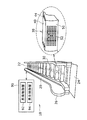
図1は、エスカレータ表示システム10の構成を説明する図である。このエスカレータ表示システム10は、エスカレータ20と制御装置90とを含み、エスカレータ20の各ステップ30に表示機能を付与したものである。
FIG. 1 is a diagram illustrating the configuration of the
エスカレータ20は、上層階乗場22と下層階乗場24の間に、複数のステップ30を無端状に接続したものを、予め定めた昇降傾斜角度で配置した昇降装置である。複数のステップ30は、制御装置90の昇降制御部92の制御の下で移動する。図1に示される欄干26は、複数のステップ30が移動する昇降路の両側に設けられ、ステップ30に乗る乗客が手で掴むことができる移動手摺を支持するものである。
The
ステップ30は、図1の右側に拡大図で示されるように、乗客が乗る踏板40と、エスカレータ20の傾斜部での蹴上げに相当するライザ50とを含む。踏板40には、滑り止め等のために、クリートと呼ばれる複数の凹凸が設けられ、これに対応して、ライザ50には、噛みこみを防ぐ等のための凹凸が設けられるが、図1の拡大図では、いずれも図示を省略してある。
As shown in an enlarged view on the right side of FIG. 1, the
ステップ30の構成については、図2以下で詳細に説明するが、ここでは、表示機能について述べる。踏板40に設けられる表示用の透光孔部44は、踏板40の背後に設けられる表示部からの表示光を導くための孔である。同様に、ライザ50に設けられる表示用の透光孔部44は、ライザ50の背後に設けられる表示部からの表示光を導くための孔である。
The configuration of
ここでは、踏板40において、欄干26側の端部に表示用の透光孔部44が設けられる。例えば、エスカレータ20が昇降運行をするときに、この表示用の透光孔部44から黄色光を点滅させるようにすることで、乗客にこの部分を踏まないようにする誘導表示の機能をもたせることができる。
Here, in the
また、ライザ50において、その表面の中央部に、マトリクス状に2次元的に整列配置された表示用の透光孔部52が設けられる。拡大図で示される例では、ライザ50の背後に設けられる表示部の「M」の文字が、複数の表示用の透光孔部52を通して認識できる。このように、ライザ50のマトリクス状に2次元配置された表示用の透光孔部52は、その背後の表示部の文字、模様をライザ50の表面に浮かび上がらせて表示する機能を有する。
Further, in the
各ライザ50における表示は、それぞれ独立に行われるが、エスカレータ20の全体として、複数のライザ50の表示を一体としてまとまったものとすることができる。図1の例では、「WELCOME」の文字が、エスカレータ20の複数のライザ50の表面に表示されている。
Although the display on each
制御装置90は、昇降制御部92と、表示制御部94を含む。昇降制御部92は、エスカレータ20におけるステップ30と欄干26の移動手摺の運行を全体として制御する。具体的には、予め設定される移動速度で、ステップ30を移動させ、これに合わせて欄干26の移動手摺を移動させる機能を有する。予め設定される移動速度としては、約30m/s等とすることができる。
The
表示制御部94は、各ステップ30に設けられる表示部の動作を全体として制御する機能を有する。後述するように、各ステップ30にはそれぞれ表示制御回路が設けられるので、制御装置90の表示制御部94は、各ステップ30の表示制御回路を全体として制御する。ここでは、予め定めた表示内容を表示部の画面に表示させる一般的な表示制御の他に、昇降制御部92と協働して、エスカレータ20の運行に合わせた表示制御を行う。
The
1つ目は、エスカレータ20の運行に合わせ、上層階乗場22と下層階乗場24との間で乗客が乗ることができるステップ30である複数の利用ステップに設けられる表示部のみを表示する。これにより、無端状に接続される複数のステップ30のうち、床下に隠れて人目につかないステップ30については表示を行わないようにでき、エスカレータ20の全体としての表示部の消費電力を抑制することができる。
The first displays only the display units provided in a plurality of usage steps, which is
2つ目は、複数の利用ステップのそれぞれの表示部の表示を独立としながら、エスカレータ20の全体として1つの表示内容を表示する全体表示制御を行う。図1の「WELCOME」表示はその1例である。
Second, overall display control for displaying one display content as the whole of the
次に、ステップ30の詳細構成について、図2から図4を用いて説明する。個々のステップ30は、それぞれが独立の部品として扱うことができるように構成される。図2は、ステップ30の側面図であり、図3は、ステップ30の正面図で、ライザ50を正面から見た図であり、図4は、ステップ30の上面図で、踏板40を上面から見た図である。
Next, the detailed configuration of
ステップ30におけるフレーム32は、踏板40の長手方向両側の下部にそれぞれ設けられる一対のブラケットと、この一対のブラケットを踏板40の長手方向に渡って接続する複数の渡し棒部材とを組み合わせた枠部材である。フレーム32は、踏板40の下部に配置されて踏板40を下方から支持する。また、フレーム32は、正面側の枠の部分で、ライザ50を裏面から支持する。また、フレーム32には、発電機側回転子74,75、
発電機増速機76,77、発電機78,79、蓄電装置80、回路基板82が取り付けられる。
The
図2において、フレーム32のライザ50の側と反対側で、踏板40の下部のところに、踏板40の長手方向の両側にそれぞれ設けられる連結部34,35は、図示されていないステップ軸が連結される部分である。このステップ軸の両端には駆動ローラがそれぞれ設けられる。駆動ローラは、エスカレータ20が昇降動作するときに、エスカレータ20の床下に延設される転送レールに案内されながら回転する。これによって、無端状に接続されたステップ30は、転送レールによって規定されるループ状の軌道に沿って移動することになる。
In FIG. 2, on the opposite side of the
ステップローラ36,37は、フレーム32のライザ50側下部に設けられ、回転軸38,39の周りに回動可能な円板状の回転部材である。ステップローラ36,37は上記の駆動ローラと異なり、ステップ30が移動することで転送レール上を転がる従動ローラで、部品としてのステップ30の構成要素である。ステップローラ36,37の直径は約75mmである。エスカレータ20の移動速度を30cm/sとすれば、ステップローラ36,37の回転数は、毎分1.27回転である。
The
回転軸38,39を介してステップローラ36,37と同軸に配置されるローラ側回転子70,71は、ベルト72,73を掛けるためのローラ側プーリである。ローラ側回転子70,71は、エスカレータ20の転送レールと干渉しない大きさに設定される。
Roller-side rotors 70 and 71 arranged coaxially with the
発電機側回転子74,75は、フレーム32に対し回転可能に支持されるプーリである。発電機側回転子74,75は、ローラ側回転子70,71との間に掛け渡されるベルト72,73を介して、ステップローラ36,37の回転エネルギを動力として受け取る機能を有する。このように、ベルト72,73は、ローラ側回転子70,71と発電機側回転子74,75の間に掛け渡されて、ステップローラ36,37側の動力を伝達する機能を有する動力伝達手段である。
The generator-
発電機側回転子74,75の直径は、ローラ側回転子70,71の直径よりも小さく設定される。(ローラ側回転子70,71の直径)/(発電機側回転子74,75の直径)=(発電機側回転子74,75の回転数)/(ローラ側回転子70,71の回転数)=(発電機側回転子74,75の回転数)/(ステップローラ36,37の回転数)=増速比となる。このように、ローラ側回転子70,71、ベルト72,73、発電機側回転子74,75は、増速機構を構成する。この増速機構を次の発電機増速機76,77と区別して、ローラ側増速機構と呼ぶことにする。ローラ側増速機構によって、発電機側回転子74,75は、ステップローラ36,37の回転数に増速比を乗じた回転数で回転する。例えば、増速比として、5程度とすることができる。
The diameter of the generator-
発電機側回転子74,75と発電機78,79との間に設けられる発電機増速機76,77は、発電機側回転子74,75の入力軸の回転数をさらに増速する機構である。具体的には、歯車式増速機構を用いることができる。発電機増速機76,77の増速比は、10から20程度とすることができる。このように、ローラ側増速機構と、発電機増速機76,77によって、ステップローラ36,37の回転数は、数十倍から百倍程度に増速され、発電に適した回転数となる。
フレーム32に取り付けられる発電機79は、入力軸の回転数に応じた発電電力を出力する回転電機である。具体的には、入力軸に永久磁石が取り付けられて回転子を構成し、モータケースにコイルが設けられて固定子を構成する。永久磁石が回転することで、固定子のコイルに鎖交する磁束が時間と共に変化し、フレミングの法則に従って、コイルに誘起電流が流れる。これによって発電が行われる。誘起電流である発電電流の大きさは磁束の時間変化の大きさに比例するので、入力軸の回転数が大きいほど、発電電流が大きくなる。上記のように、ローラ側増速機構と、発電機増速機76,77によって、ステップローラ36,37の回転数は、数十倍から百倍程度に増速されるので、発電電流も、その分大きくなる。
A
蓄電装置80は、発電電力を蓄電し、蓄電された電力を負荷に供給する充放電可能な2次電池である。蓄電装置としては、キャパシタ、蓄電池等を用いることができる。
The
回路基板82は、表示制御回路84が搭載される基板で、表示制御回路84には蓄電装置80から電力が供給される。
The
表示制御回路84は、ライザ50の背面に取り付けられる表示パネル60の動作を制御する回路である。具体的には、表示パネル60を構成する複数の発光素子62を作動させる駆動回路と、駆動回路の動作を制御する制御ICとで構成される。制御ICは、エスカレータ20の制御装置90の表示制御部94からの制御信号によって駆動回路を制御する。また、これとは別に、表示プログラムを内蔵するメモリを有し、その表示プログラムに従って駆動回路の動作を制御するものとしてもよい。
The
表示制御回路84は、ステップ30の周辺の明るさに応じて、駆動回路の動作を制御する機能を有する。ステップ30の周辺の明るさは、踏板40周辺の明るさを検出するセンサ、ライザ50周辺の明るさを検出するセンサを用い、これらのセンサの検出結果に応じて、駆動回路の動作を停止し、あるいは発光素子62の輝度を調整する。
The
これによって、踏板40やライザ周辺が暗いときは発光素子の輝度を低くし、踏板40やライザ周辺が明るいときは発光素子の輝度を高くする。このようにすることで、踏板40における表示、ライザ50における表示が人間の目の視認の観点から十分なものとしつつ、表示パネル60に関する消費電力を抑制することができる。
Thus, the brightness of the light emitting element is lowered when the area around the
エスカレータ20に乗客が多く乗って、その足や身体によってライザ50の表示があまり視認できないことが生じる。そのような状況のときは、踏板40の周辺、ライザ50の周辺が暗くなるので、明るさ検出のためのセンサによって検出ができる。その他に、踏板40やライザ50に反射光検出センサを設け、踏板40の上に乗客の足があるか否かを検出するものとしてもよい。これらの手段によって、ライザ50の表示があまり視認できない状況であると判断されるときには、表示制御回路84は、表示パネル60の動作を停止させる。これによって、無駄な表示を行わず、消費電力を抑制することができる。
A large number of passengers ride on the
表示パネル60は、図2に示されるように、ライザ50の背面に取り付けられる表示部である。具体的には、図3に示されるように、マトリクス状に、発光素子62を2次元的に整列配置したパネルである。発光素子62としては、発光ダイオードを用いることができる。図3の例では、6行13列の合計78個の発光素子62が配列されている。各発光素子62は、それぞれ表示制御回路64によって動作が制御される。
As shown in FIG. 2, the
図3において、ライザ50に設けられる表示用の透光孔部52は、表示部である表示パネル60の発光素子62の表示光を外部に導くための孔である。したがって、エスカレータ20を利用する乗客は、この表示用の透光孔部52を通して、表示部である表示パネル60の表示内容を視認する。その観点では、表示用の透光孔部52がライザ50における表示部ということもできるが、ここでは、表示部はあくまでライザ50の背後にある表示パネル60であって、透光孔部52は、その表示部の表示光を外部に導くための孔にすぎない。
In FIG. 3, a
透光孔部52は、ライザ50の表面の凹凸の溝部の部分に貫通して設けられる。透光孔部52は、貫通孔に異物等が入って透光性を妨げないように、適当な透光性を有する樹脂等が充填されることが好ましい。ライザ50における透光孔部52の配置は、表示パネル60の発光素子62の2次元整列配置と同じ配列ピッチである。換言すれば、ライザ50に表示パネル60を取り付けると、表示パネル60の各発光素子62の位置に対応する位置にそれぞれ透光孔部52が来る。なお、透光孔部52の直径の大きさは、表示パネル60に配置される発光素子62の発光面積に相当する直径よりも小さく設定することがよい。
The light
このように透光孔部52をライザ50に設けることで、ライザ50の背後の表示パネル60の各発光素子62の点滅による表示内容が、エスカレータ20を利用する乗客によって、そのまま、ライザ50の表面に視認される。
By providing the
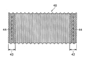
図4は、踏板40における表示用の透光孔部44の配置を説明する図である。踏板40の背後には、この透光孔部44の配置に対応して発光素子が配置される表示パネルが表示部として設けられることは、ライザ50の場合と同様である。
FIG. 4 is a view for explaining the arrangement of the light transmitting
踏板40における透光孔部44は、図1でも述べたように、踏板40の欄干26側の両端部に設けられる。一般的なエスカレータにおいて、踏板40の欄干26側の両端部は、例えば、黄色く塗装されたセフティライン42,43が設けられる。このセフティライン42,43は、そこに乗客が乗ると、欄干26側と乗客の足等が干渉することがあるので、そのことを注意するために、色を異ならせてある。
As described in FIG. 1, the light transmitting
踏板40における透光孔部44は、このセフティライン42,43の範囲における表面の凹凸の溝部の部分に貫通して設けられる。透光孔部44に適当な透光性樹脂を充填することが好ましいこともライザ50における透光孔部52と同様である。このように、セフティライン42の範囲に透光孔部44を設け、その背後の表示部において発光素子を点灯または点滅させることで、その範囲に乗らないように、乗客により一層注意を促すことができる。
The
ライザ50の場合と同様に、踏板40にもマトリクス状に2次元的に透光孔部を整列配置することもできる。この場合、ライザ50には乗客の体重が掛からないのに対し、踏板40には乗客の体重が掛かるので、強度的な配慮が必要である。例えば、透光孔部の配置ピッチを広げて、踏板40に要求される強度を確保するようにしてもよい。あるいは、踏板40の背後に補強板を配置して、透光孔部による強度低下を補うようにしてもよい。
As in the case of the
本発明に係るエスカレータ用ステップ及びこれを用いるエスカレータ表示システムは、一般乗客が利用するエスカレータに用いることができる。 The escalator step according to the present invention and the escalator display system using the escalator step can be used for an escalator used by general passengers.
10 エスカレータ表示システム、20 エスカレータ、22 上層階乗場、24 下層階乗場、26 欄干、30 ステップ、32 フレーム、34,35 連結部、36,37 ステップローラ、38,39 回転軸、40 踏板、42,43 セフティライン、44,52 透光孔部、50 ライザ、60 表示パネル、62 発光素子、64 表示制御回路、70,71 ローラ側回転子、72,73 ベルト、74,75 発電機側回転子、76,77 発電機増速機、78,79 発電機、80 蓄電装置、82 回路基板、84 表示制御回路、90 制御装置、92 昇降制御部、94 表示制御部。 10 escalator display system, 20 escalator, 22 upper floor landing, 24 lower floor landing, 26 balustrade, 30 steps, 32 frames, 34, 35 connecting portion, 36, 37 step rollers, 38, 39 rotating shaft, 40 tread, 42, 43 safety lines, 44, 52 light-transmitting hole, 50 riser, 60 display panel, 62 light emitting element, 64 display control circuit, 70, 71 roller side rotor, 72, 73 belt, 74, 75 generator side rotor, 76,77 generator speed increaser, 78,79 generator, 80 power storage device, 82 circuit board, 84 display control circuit, 90 control device, 92 lift control unit, 94 display control unit.
Claims (6)
踏板の下部に配置されて踏板を下方から支持するフレームと、
フレームに配置され、エスカレータの傾斜部での蹴上げに相当するライザと、
フレームのライザ側下部に回動可能に設けられ、エスカレータが昇降動作すると共に回転する一対のステップローラと、
ステップローラの回転速度を増速する増速機構と、
増速機構に接続され、回転速度に応じた発電電力を出力する発電機と、
発電電力を蓄電する蓄電装置と、
踏板またはライザに設けられ、蓄電装置からの電力によって表示を行う表示部と、
を備えることを特徴とするエスカレータ用ステップ。 A tread on which passengers on the escalator ride,
A frame that is arranged at the bottom of the tread and supports the tread from below;
A riser which is arranged in the frame and corresponds to kicking in the inclined part of the escalator;
A pair of step rollers that are rotatably provided at the lower part of the riser side of the frame, and the escalator moves up and down, and rotate,
A speed increasing mechanism for increasing the rotation speed of the step roller;
A generator that is connected to the speed increasing mechanism and outputs generated power according to the rotational speed;
A power storage device for storing generated power; and
A display unit that is provided on the tread board or the riser and performs display by the electric power from the power storage device;
An escalator step comprising:
表示部は、踏板またはライザの背後に設けられ、
表示部が設けられる踏板またはライザは、表示部からの光を通す透光孔部を有することを特徴とするエスカレータ用ステップ。 In the escalator step according to claim 1,
The display is provided behind the tread or riser,
The step board or riser provided with a display part has a translucent hole part through which the light from a display part passes, The step for escalators characterized by the above-mentioned.
踏板周辺の明るさまたはライザ周辺の明るさを検知する検知部と、
検知部の検知結果に応じ、表示部に対する表示制御を行う表示制御回路と、
を備えることを特徴とするエスカレータ用ステップ。 In the escalator step according to claim 2,
A detection unit for detecting the brightness around the tread board or the brightness around the riser;
A display control circuit that performs display control on the display unit according to the detection result of the detection unit;
An escalator step comprising:
増速機構は、
ステップローラの回転軸と同軸に設けられローラ側回転子と、
発電機の入力軸に同軸に設けられ、ローラ側回転子の外径に対し予め定めた増速比で定まる外径を有する発電機側回転子と、
を含むことを特徴とするエスカレータ用ステップ。 In the escalator step according to claim 3,
The speed increasing mechanism
A roller side rotor provided coaxially with the rotation axis of the step roller;
A generator-side rotor which is provided coaxially with the input shaft of the generator and has an outer diameter determined by a predetermined speed increasing ratio with respect to the outer diameter of the roller-side rotor;
Step for escalator characterized by including.
各ステップの踏板またはライザに設けられる表示部と、
エスカレータの運行に合わせ、下層階乗場と上層階乗場との間で乗客が乗ることができるステップである複数の利用ステップに設けられる表示部のみを表示する制御を行う表示制御部と、
を備え、
ステップは、
エスカレータが昇降動作すると共に回転する一対のステップローラと、
ステップローラの回転速度を増速する増速機構と、
増速機構に接続され、回転速度に応じた発電電力を出力する発電機と、
発電電力を蓄電し、表示部に表示電力を供給する蓄電装置と、
を含むことを特徴とするエスカレータ表示システム。 An escalator disposed between the lower floor landing and the upper floor landing at a predetermined ascending / descending inclination angle by connecting a plurality of steps including a step board on which a passenger rides and a riser corresponding to a kick-up in an endless manner,
A display provided on the step board or riser of each step;
In accordance with the operation of the escalator, a display control unit that performs control to display only the display unit provided in a plurality of usage steps that are steps in which passengers can ride between the lower floor landing and the upper floor landing,
With
The steps are
A pair of step rollers rotating as the escalator moves up and down;
A speed increasing mechanism for increasing the rotation speed of the step roller;
A generator that is connected to the speed increasing mechanism and outputs generated power according to the rotational speed;
A power storage device that stores generated power and supplies display power to the display unit;
An escalator display system comprising:
表示制御部は、
複数の利用ステップのそれぞれの表示部の表示を独立としながら全体として1つの表示内容を表示する全体表示制御を行うことを特徴とするエスカレータ表示システム。 In the escalator display system according to claim 5,
The display control unit
An escalator display system characterized by performing overall display control for displaying one display content as a whole while independently displaying each display unit of a plurality of usage steps.
Priority Applications (1)
| Application Number | Priority Date | Filing Date | Title |
|---|---|---|---|
| JP2011026846A JP2012166865A (en) | 2011-02-10 | 2011-02-10 | Step for escalator and escalator display system |
Applications Claiming Priority (1)
| Application Number | Priority Date | Filing Date | Title |
|---|---|---|---|
| JP2011026846A JP2012166865A (en) | 2011-02-10 | 2011-02-10 | Step for escalator and escalator display system |
Publications (1)
| Publication Number | Publication Date |
|---|---|
| JP2012166865A true JP2012166865A (en) | 2012-09-06 |
Family
ID=46971413
Family Applications (1)
| Application Number | Title | Priority Date | Filing Date |
|---|---|---|---|
| JP2011026846A Withdrawn JP2012166865A (en) | 2011-02-10 | 2011-02-10 | Step for escalator and escalator display system |
Country Status (1)
| Country | Link |
|---|---|
| JP (1) | JP2012166865A (en) |
Cited By (6)
| Publication number | Priority date | Publication date | Assignee | Title |
|---|---|---|---|---|
| EP2716589A1 (en) * | 2012-10-02 | 2014-04-09 | Inventio AG | Displaying information using escalator steps |
| US9346654B2 (en) * | 2014-05-29 | 2016-05-24 | Goldstein Biomedical Consultants Llc | Regenerative power capture system for endless track escalators and moving walkways |
| WO2020012541A1 (en) * | 2018-07-09 | 2020-01-16 | 三菱電機株式会社 | Display control system and display control method |
| DE102020132019A1 (en) | 2020-12-02 | 2022-06-02 | Tk Elevator Innovation And Operations Gmbh | Safety device for an escalator |
| KR20240159125A (en) * | 2023-04-28 | 2024-11-05 | 한순환 | Advertising system for escalators |
| JP7659748B1 (en) | 2024-04-09 | 2025-04-10 | フジテック株式会社 | Man Conveyor |
-
2011
- 2011-02-10 JP JP2011026846A patent/JP2012166865A/en not_active Withdrawn
Cited By (17)
| Publication number | Priority date | Publication date | Assignee | Title |
|---|---|---|---|---|
| EP2716589A1 (en) * | 2012-10-02 | 2014-04-09 | Inventio AG | Displaying information using escalator steps |
| CN107074505B (en) * | 2014-05-29 | 2019-03-12 | 戈德斯坦生物医学顾问有限责任公司 | Regenerative power capture system for endless track escalators and moving walks |
| US10752468B2 (en) * | 2014-05-29 | 2020-08-25 | Goldstein Biomedical Consultants Llc | Regenerative power capture system for endless track escalators and moving walkways |
| CN107074505A (en) * | 2014-05-29 | 2017-08-18 | 戈德斯坦生物医学顾问有限责任公司 | Regenerative Power Capture System for Endless Track Escalators and Moving Walkways |
| JP2017526594A (en) * | 2014-05-29 | 2017-09-14 | ゴールドスタイン バイオメディカル コンサルタンツ リミテッド ライアビリティ カンパニー | Regenerative power capture system for endless truck escalators and moving walkways |
| US10017360B2 (en) * | 2014-05-29 | 2018-07-10 | Goldstein Biomedical Consultants Llc | Regenerative power capture system for endless track escalators and moving walkways |
| EP3148918A4 (en) * | 2014-05-29 | 2018-10-17 | Goldstein, Harold, A. | Regenerative power capture system for endless track escalators and moving walkways |
| US20160311660A1 (en) * | 2014-05-29 | 2016-10-27 | Goldstein Biomedical Consultants Llc | Regenerative power capture system for endless track escalators and moving walkways |
| US20180297819A1 (en) * | 2014-05-29 | 2018-10-18 | Goldstein Biomedical Consultants Llc | Regenerative power capture system for endless track escalators and moving walkways |
| CN110092278A (en) * | 2014-05-29 | 2019-08-06 | 戈德斯坦生物医学顾问有限责任公司 | Regenerating power capture systems for endless track escalator and moving elevator |
| US9346654B2 (en) * | 2014-05-29 | 2016-05-24 | Goldstein Biomedical Consultants Llc | Regenerative power capture system for endless track escalators and moving walkways |
| WO2020012541A1 (en) * | 2018-07-09 | 2020-01-16 | 三菱電機株式会社 | Display control system and display control method |
| DE102020132019A1 (en) | 2020-12-02 | 2022-06-02 | Tk Elevator Innovation And Operations Gmbh | Safety device for an escalator |
| KR20240159125A (en) * | 2023-04-28 | 2024-11-05 | 한순환 | Advertising system for escalators |
| KR102914315B1 (en) * | 2023-04-28 | 2026-01-20 | 한순환 | Advertising system for escalators |
| JP7659748B1 (en) | 2024-04-09 | 2025-04-10 | フジテック株式会社 | Man Conveyor |
| JP2025159820A (en) * | 2024-04-09 | 2025-10-22 | フジテック株式会社 | Man Conveyor |
Similar Documents
| Publication | Publication Date | Title |
|---|---|---|
| JP2012166865A (en) | Step for escalator and escalator display system | |
| US8641073B2 (en) | Apparatus for adjusting the height of a saddle for a bicycle | |
| KR101238068B1 (en) | Safety device of elevator door for hand protection using plastic optical sheet | |
| KR101036096B1 (en) | Exercise bike | |
| US6755283B2 (en) | Spiral propeller | |
| KR200453025Y1 (en) | Rail bike | |
| US9356477B2 (en) | Rotation assistance mechanism and rotating power mechanism equipped with same | |
| CN101948072B (en) | Gravitation energy-saving escalator for ascending and descending | |
| JP5781466B2 (en) | Passenger conveyor step lighting system | |
| KR101181472B1 (en) | Step running machine | |
| CN106698171A (en) | passenger conveyor | |
| CN205591617U (en) | Two -layer parking equipment's two -speed motor ball screw pulls elevating gear | |
| KR100930542B1 (en) | Self-powered health game device applied to parks, children's playgrounds and landscaping | |
| CN204952073U (en) | Take treadmill of thought -read rate function | |
| CN100404091C (en) | Outer rail tower jumping machine | |
| CN2741942Y (en) | Full actuating building window and balcony taking and collecting newspaper and cargo machine | |
| CN201269035Y (en) | Electric self-balancing door curtain | |
| JP2009113891A (en) | Power converter of elevator | |
| WO2009034630A1 (en) | Elevator | |
| JP5448946B2 (en) | Passenger conveyor | |
| JP5638226B2 (en) | Parking gate | |
| CN211169681U (en) | Vertical elevator | |
| CN102678859A (en) | Transmission structure of flagpole movement | |
| JPH11209056A (en) | Escalator | |
| CN117899416B (en) | Exercise rowing machine |
Legal Events
| Date | Code | Title | Description |
|---|---|---|---|
| A300 | Withdrawal of application because of no request for examination |
Free format text: JAPANESE INTERMEDIATE CODE: A300 Effective date: 20140513 |