JP2012167601A - Control device of internal combustion engine - Google Patents
Control device of internal combustion engine Download PDFInfo
- Publication number
- JP2012167601A JP2012167601A JP2011029186A JP2011029186A JP2012167601A JP 2012167601 A JP2012167601 A JP 2012167601A JP 2011029186 A JP2011029186 A JP 2011029186A JP 2011029186 A JP2011029186 A JP 2011029186A JP 2012167601 A JP2012167601 A JP 2012167601A
- Authority
- JP
- Japan
- Prior art keywords
- internal combustion
- combustion engine
- exhaust
- control
- intake
- Prior art date
- Legal status (The legal status is an assumption and is not a legal conclusion. Google has not performed a legal analysis and makes no representation as to the accuracy of the status listed.)
- Pending
Links
Images



Classifications
-
- Y—GENERAL TAGGING OF NEW TECHNOLOGICAL DEVELOPMENTS; GENERAL TAGGING OF CROSS-SECTIONAL TECHNOLOGIES SPANNING OVER SEVERAL SECTIONS OF THE IPC; TECHNICAL SUBJECTS COVERED BY FORMER USPC CROSS-REFERENCE ART COLLECTIONS [XRACs] AND DIGESTS
- Y02—TECHNOLOGIES OR APPLICATIONS FOR MITIGATION OR ADAPTATION AGAINST CLIMATE CHANGE
- Y02T—CLIMATE CHANGE MITIGATION TECHNOLOGIES RELATED TO TRANSPORTATION
- Y02T10/00—Road transport of goods or passengers
- Y02T10/10—Internal combustion engine [ICE] based vehicles
- Y02T10/12—Improving ICE efficiencies
Landscapes
- Exhaust-Gas Circulating Devices (AREA)
- Output Control And Ontrol Of Special Type Engine (AREA)
Abstract
【課題】EGR装置を備えた過給機付きエンジンにおいて、EGRガスによる減速時の失火を防止できるようにする。
【解決手段】エンジン11の減速時に排気圧を低下させる排気圧低下制御(例えばウェイストゲートバルブ27を開弁させる制御や排気バルブの閉弁時期を上死点近傍へ遅角する制御等)を実行することで、内部EGRガス(気筒内に残留する燃焼ガス)の排気を促進して、内部EGRガス量を減少させる。これにより、減速時に吸気管12内に滞留する外部EGRガス(EGR装置28により還流されたEGRガス)が過剰に多い状態であっても、気筒内に充填される総EGRガス量(外部EGRガス量+内部EGRガス量)の増加を抑制するか又は気筒内に充填される総EGRガス量を減少させて、燃料カット制御を実施できない状況でもEGRガスによる減速時の失火を防止する。
【選択図】図1In a supercharged engine equipped with an EGR device, misfire at the time of deceleration due to EGR gas can be prevented.
Exhaust pressure reduction control for reducing exhaust pressure when the engine 11 is decelerated (for example, control for opening a waste gate valve 27 or control for delaying the closing timing of the exhaust valve to near the top dead center). As a result, exhaust of internal EGR gas (combustion gas remaining in the cylinder) is promoted, and the amount of internal EGR gas is reduced. Thereby, even if the external EGR gas (EGR gas recirculated by the EGR device 28) staying in the intake pipe 12 during deceleration is excessively large, the total amount of EGR gas (external EGR gas) charged in the cylinder Increase in the amount + internal EGR gas amount) or the total amount of EGR gas charged in the cylinder is reduced to prevent misfire during deceleration due to EGR gas even in a situation where fuel cut control cannot be performed.
[Selection] Figure 1
Description
本発明は、内燃機関の排気通路から排出ガスの一部をEGRガスとして吸気通路へ還流させるEGR装置を備えた内燃機関の制御装置に関する発明である。 The present invention relates to an internal combustion engine control device including an EGR device that recirculates a part of exhaust gas from an exhaust passage of an internal combustion engine to an intake passage as EGR gas.
近年、車両に搭載される内燃機関(エンジン)においては、出力性能を確保しながら燃費を向上させるために、小排気量のエンジンに過給機を搭載した過給ダウンサイジングエンジンを採用するようにしたものがある。この過給ダウンサイジングエンジンは、高負荷運転の頻度が増加してノックが発生し易くなるため、排気通路から排出ガスの一部をEGRガスとして吸気通路へ還流させるEGR装置を搭載してノックの発生を抑制するようにしたものがある。 In recent years, internal combustion engines (engines) mounted on vehicles have adopted supercharged downsizing engines that are equipped with a supercharger in a small displacement engine in order to improve fuel efficiency while ensuring output performance. There is what I did. Since this supercharged downsizing engine increases the frequency of high-load operation and is likely to generate knock, an EGR device that recirculates a part of the exhaust gas from the exhaust passage as EGR gas to the intake passage is installed. Some have been designed to suppress the occurrence.
しかし、EGR装置を搭載したエンジンは、減速時にスロットル開度(スロットルバルブの開度)を閉じ側に制御したときに、EGR弁を閉弁するようにしても、スロットルバルブの上流側の吸気通路内にEGRガスが滞留して、EGRガスが過剰に多い状態となるため、失火が発生し易くなるという問題がある。 However, in an engine equipped with an EGR device, the intake passage on the upstream side of the throttle valve may be closed even if the EGR valve is closed when the throttle opening (throttle valve opening) is controlled to the closed side during deceleration. There is a problem that misfire is likely to occur because the EGR gas stays inside and the EGR gas becomes excessively large.
この対策として、例えば、特許文献1(特開2010−77898号公報)に記載されているように、EGR装置を搭載したエンジンにおいて、減速時に燃料カット制御(燃料噴射を停止する制御)を実施する時期を早くすることで、EGRガスによる減速時の失火を防止するようにしたものがある。 As a countermeasure, for example, as described in Patent Document 1 (Japanese Patent Laid-Open No. 2010-77898), in an engine equipped with an EGR device, fuel cut control (control to stop fuel injection) is performed during deceleration. There is one that prevents misfire during deceleration by EGR gas by making the timing earlier.
しかし、上記特許文献1の技術では、過給ダウンサイジングエンジンのように低回転高負荷運転状態でEGR装置を作動させる場合、低回転高負荷運転からの減速時に、燃料カット制御を実施する時期を早くして失火を防止しようとしても、エンジン回転速度が低いため燃料カット制御を実施することができず、EGRガスによる減速時の失火を防止できない可能性がある。 However, in the technique of the above-mentioned Patent Document 1, when the EGR device is operated in a low-rotation and high-load operation state like a supercharged downsizing engine, the timing for performing the fuel cut control at the time of deceleration from the low-rotation and high-load operation is determined. Even if it tries to prevent misfire early, fuel cut control cannot be performed because the engine rotation speed is low, and misfire during deceleration due to EGR gas may not be prevented.
そこで、本発明が解決しようとする課題は、燃料カット制御を実施できない状況でもEGRガスによる減速時の失火を防止することができる内燃機関の制御装置を提供することにある。 Therefore, the problem to be solved by the present invention is to provide a control device for an internal combustion engine that can prevent misfire during deceleration by EGR gas even in a situation where fuel cut control cannot be performed.
上記課題を解決するために、請求項1に係る発明は、内燃機関の排気通路から排出ガスの一部をEGRガスとして吸気通路へ還流させるEGR装置を備えた内燃機関の制御装置において、内燃機関の減速時に排気圧を低下させる排気圧低下制御を実行する制御手段を備えた構成としたものである。 In order to solve the above-mentioned problems, an invention according to claim 1 is directed to an internal combustion engine control apparatus including an EGR device that recirculates a part of exhaust gas from an exhaust passage of an internal combustion engine to an intake passage as EGR gas. The control means for executing the exhaust pressure lowering control for reducing the exhaust pressure at the time of deceleration is provided.
減速時に排気圧低下制御を実行して排気圧を低下させれば、内部EGRガス(気筒内に残留する燃焼ガス)の排気を促進して、内部EGRガス量を減少させることができる。これにより、減速時に吸気通路内に滞留する外部EGRガス(EGR装置により還流されたEGRガス)が過剰に多い状態であっても、気筒内に充填される総EGRガス量(外部EGRガス量+内部EGRガス量)の増加を抑制するか又は気筒内に充填される総EGRガス量を減少させることができ、燃料カット制御を実施できない状況でもEGRガスによる減速時の失火を防止することができる。 If exhaust pressure reduction control is executed during deceleration to reduce exhaust pressure, exhaust of internal EGR gas (combustion gas remaining in the cylinder) can be promoted to reduce the amount of internal EGR gas. Thus, even when the amount of external EGR gas (EGR gas recirculated by the EGR device) staying in the intake passage during deceleration is excessively large, the total amount of EGR gas charged in the cylinder (external EGR gas amount + The increase in the internal EGR gas amount) can be suppressed or the total EGR gas amount charged in the cylinder can be reduced, and misfire during deceleration due to EGR gas can be prevented even in a situation where fuel cut control cannot be performed. .
具体的には、請求項2のように、排気通路に設けられた排気タービンで吸気通路に設けられたコンプレッサを駆動して吸入空気を過給する過給機と、排気タービンをバイパスする排気バイパス通路を開閉するウェイストゲートバルブとを備えたシステムでは、減速時にウェイストゲートバルブを開弁させることで排気圧低下制御を実行するようにしても良い。ウェイストゲートバルブを開弁させれば、排気タービンをバイパスして流れる排出ガス量を増加させて、排気圧を低下させることができ、内部EGRガスの排気を促進することができる。 Specifically, as in claim 2, a turbocharger that supercharges intake air by driving a compressor provided in the intake passage by an exhaust turbine provided in the exhaust passage, and an exhaust bypass that bypasses the exhaust turbine In a system including a waste gate valve that opens and closes a passage, exhaust pressure reduction control may be executed by opening the waste gate valve during deceleration. If the waste gate valve is opened, the amount of exhaust gas flowing by bypassing the exhaust turbine can be increased, the exhaust pressure can be lowered, and the exhaust of the internal EGR gas can be promoted.
また、請求項3のように、内燃機関の排気バルブのバルブ開閉特性(例えば、リフト量、作用角、開閉時期等)を変化させる可変バブル機構を備えたシステムでは、減速時に可変バブル機構により排気バルブのバルブ開閉特性を排気圧の低下方向に変化させることで排気圧低下制御を実行するようにしても良い。この場合、例えば、排気バルブのリフト量を増加させる、或は、排気バルブの作用角を広くする、或は、排気バルブの閉弁時期を上死点から遠ざかるよう進角する。このようにすれば、気筒内から排気バルブのバルブ開口部を通して排出ガスが排出される際の圧損を小さくして、排気圧を低下させることができ、内部EGRガスの排気を促進することができる。 Further, in a system having a variable bubble mechanism for changing the valve opening / closing characteristics (for example, lift amount, operating angle, opening / closing timing, etc.) of the exhaust valve of the internal combustion engine as in claim 3, the variable bubble mechanism is used for exhausting during deceleration. The exhaust pressure reduction control may be executed by changing the valve opening / closing characteristics of the valve in the direction of decreasing the exhaust pressure. In this case, for example, the lift amount of the exhaust valve is increased, the working angle of the exhaust valve is increased, or the closing timing of the exhaust valve is advanced to move away from the top dead center. In this way, it is possible to reduce the pressure loss when exhaust gas is exhausted from the cylinder through the valve opening of the exhaust valve, reduce the exhaust pressure, and promote the exhaust of the internal EGR gas. .
また、本発明は、請求項4のように、内燃機関の排気通路から排出ガスの一部をEGRガスとして吸気通路へ還流させるEGR装置を備えた内燃機関の制御装置において、内燃機関の減速時に吸気通路内のEGRガスが吸入空気に交換される速度を上昇させる交換速度上昇制御を実行する制御手段を備えた構成としても良い。 According to a fourth aspect of the present invention, there is provided a control device for an internal combustion engine comprising an EGR device that recirculates a part of exhaust gas from the exhaust passage of the internal combustion engine to the intake passage as EGR gas. It is good also as a structure provided with the control means which performs the exchange speed raise control which raises the speed by which EGR gas in an intake passage is exchanged with intake air.
減速時に交換速度上昇制御を実行して吸気通路内のEGRガスが吸入空気に交換される速度(EGRガスが吸入空気に入れ替わる速度)を上昇させれば、吸気通路内に滞留するEGRガスの掃気を促進することができる。これにより、減速時に吸気通路内のEGRガスを速やかに減少させて、気筒内に充填されるEGRガス量を早期に減少させることができ、燃料カット制御を実施できない状況でも減速時の早期からEGRガスによる失火を防止することができる。 If the exchange speed increase control is executed at the time of deceleration to increase the speed at which the EGR gas in the intake passage is replaced with the intake air (the speed at which the EGR gas is replaced with the intake air), the scavenging of the EGR gas staying in the intake passage Can be promoted. As a result, the EGR gas in the intake passage can be quickly reduced during deceleration, and the amount of EGR gas charged in the cylinder can be reduced early. Even in a situation where fuel cut control cannot be performed, EGR is started from the early stage during deceleration. Misfire due to gas can be prevented.
具体的には、請求項5のように、内燃機関の吸入空気を冷却する吸入空気冷却手段を備えたシステムでは、減速時に吸入空気冷却手段の冷却能力を高めることで交換速度上昇制御を実行するようにしても良い。吸入空気冷却手段(例えばインタークーラ等)の冷却能力を高めれば、吸入空気の温度を低下させて吸入空気の体積を減少させることができ、その分、気筒内に吸入可能なEGRガス量を増加させて、吸気通路内のEGRガスが吸入空気に交換される速度を上昇させることができ、吸気通路内に滞留するEGRガスの掃気を促進することができる。 Specifically, as described in claim 5, in the system including the intake air cooling means for cooling the intake air of the internal combustion engine, the exchange speed increase control is executed by increasing the cooling capacity of the intake air cooling means at the time of deceleration. You may do it. If the cooling capacity of the intake air cooling means (for example, intercooler) is increased, the intake air temperature can be decreased to reduce the volume of the intake air, and the amount of EGR gas that can be sucked into the cylinder is increased accordingly. Thus, the speed at which the EGR gas in the intake passage is exchanged with the intake air can be increased, and scavenging of the EGR gas staying in the intake passage can be promoted.
また、請求項6のように、EGRガスを冷却するEGRガス冷却手段を備えたシステムでは、減速時にEGRガス冷却手段の冷却能力を高めることで交換速度上昇制御を実行するようにしても良い。EGRガス冷却手段の冷却能力を高めれば、EGRガスの温度を低下させてEGRガスの体積を減少させることができ、その分、気筒内に吸入可能なEGRガス量を増加させて、吸気通路内のEGRガスが吸入空気に交換される速度を上昇させることができ、吸気通路内に滞留するEGRガスの掃気を促進することができる。 Further, in the system having the EGR gas cooling means for cooling the EGR gas as in the sixth aspect, the replacement speed increase control may be executed by increasing the cooling capacity of the EGR gas cooling means at the time of deceleration. If the cooling capacity of the EGR gas cooling means is increased, the temperature of the EGR gas can be lowered to reduce the volume of the EGR gas, and the amount of EGR gas that can be sucked into the cylinder is increased accordingly, and the inside of the intake passage is increased. The rate at which the EGR gas is exchanged with the intake air can be increased, and scavenging of the EGR gas staying in the intake passage can be promoted.
更に、請求項7のように、減速時に内燃機関の回転速度を上昇させることで交換速度上昇制御を実行するようにしても良い。内燃機関の回転速度を上昇させれば、単位時間当りに気筒内に吸入可能なEGRガス量を増加させて、吸気通路内のEGRガスが吸入空気に交換される速度を上昇させることができ、吸気通路内に滞留するEGRガスの掃気を促進することができる。 Further, as described in claim 7, the replacement speed increase control may be executed by increasing the rotational speed of the internal combustion engine during deceleration. If the rotational speed of the internal combustion engine is increased, the amount of EGR gas that can be sucked into the cylinder per unit time can be increased, and the speed at which the EGR gas in the intake passage is exchanged with intake air can be increased. The scavenging of EGR gas staying in the intake passage can be promoted.
また、本発明は、請求項8のように、内燃機関の排気通路から排出ガスの一部をEGRガスとして吸気通路へ還流させるEGR装置を備えた内燃機関の制御装置において、内燃機関の減速時に吸気抵抗を低下させる吸気抵抗低下制御を実行する制御手段を備えた構成としても良い。 According to another aspect of the present invention, there is provided a control device for an internal combustion engine comprising an EGR device that recirculates a part of exhaust gas from the exhaust passage of the internal combustion engine to the intake passage as EGR gas. It is good also as a structure provided with the control means which performs the intake resistance fall control which reduces an intake resistance.
減速時に吸気抵抗低下制御を実行して吸気抵抗を低下させれば、吸入空気(新気)の導入を促進して、吸気通路内に滞留するEGRガスの掃気を促進することができる。これにより、減速時に吸気通路内のEGRガスを速やかに減少させて、気筒内に充填されるEGRガス量を早期に減少させることができ、燃料カット制御を実施できない状況でも減速時の早期からEGRガスによる失火を防止することができる。 If intake resistance lowering control is executed during deceleration to reduce intake resistance, introduction of intake air (fresh air) can be promoted and scavenging of EGR gas staying in the intake passage can be promoted. As a result, the EGR gas in the intake passage can be quickly reduced during deceleration, and the amount of EGR gas charged in the cylinder can be reduced early. Even in a situation where fuel cut control cannot be performed, EGR is started from the early stage during deceleration. Misfire due to gas can be prevented.
具体的には、請求項9のように、内燃機関の吸気バルブのバルブ開閉特性(例えば、リフト量、作用角、開閉時期等)を変化させる可変バブル機構を備えたシステムでは、減速時に可変バブル機構により吸気バルブのバルブ開閉特性を吸気抵抗の低下方向に変化させることで吸気抵抗低下制御を実行するようにしても良い。この場合、例えば、吸気バルブのリフト量を増加させる、或は、吸気バルブの作用角を広くする、或は、吸気バルブの開弁時期を上死点近傍へ進角する。このようにすれば、吸気バルブのバルブ開口部を通して気筒内へ吸入空気が吸入される際の吸気抵抗を低下させることができ、これにより、吸入空気(新気)の導入を促進して、吸気通路内に滞留するEGRガスの掃気を促進することができる。 Specifically, as in claim 9, in a system including a variable bubble mechanism that changes the valve opening / closing characteristics (for example, lift amount, operating angle, opening / closing timing, etc.) of an intake valve of an internal combustion engine, The intake resistance reduction control may be executed by changing the valve opening / closing characteristics of the intake valve in the direction of decreasing the intake resistance by a mechanism. In this case, for example, the lift amount of the intake valve is increased, the operating angle of the intake valve is increased, or the opening timing of the intake valve is advanced to the vicinity of the top dead center. In this way, it is possible to reduce the intake resistance when the intake air is drawn into the cylinder through the valve opening of the intake valve, thereby promoting the introduction of the intake air (fresh air) and the intake air. The scavenging of the EGR gas staying in the passage can be promoted.
また、本発明は、請求項10のように、内燃機関の排気通路から排出ガスの一部をEGRガスとして吸気通路へ還流させるEGR装置を備えた内燃機関の制御装置において、内燃機関の減速時に吸気通路へ強制的に新気(空気)を導入する新気導入制御を実行する制御手段を備えた構成としても良い。 According to a tenth aspect of the present invention, there is provided a control device for an internal combustion engine including an EGR device that recirculates a part of exhaust gas from the exhaust passage of the internal combustion engine to the intake passage as EGR gas when the internal combustion engine is decelerated. A configuration may be provided that includes control means for executing fresh air introduction control for forcibly introducing fresh air (air) into the intake passage.
減速時に新気導入制御を実行して強制的に新気を導入すれば、強制的に導入した新気によって、吸気通路内に滞留するEGRガスの掃気を促進することができる。これにより、減速時に吸気通路内のEGRガスを速やかに減少させて、気筒内に充填されるEGRガス量を早期に減少させることができ、燃料カット制御を実施できない状況でも減速時の早期からEGRガスによる失火を防止することができる。 When new air is forcibly introduced by executing the fresh air introduction control at the time of deceleration, the scavenging of the EGR gas staying in the intake passage can be promoted by the forcibly introduced new air. As a result, the EGR gas in the intake passage can be quickly reduced during deceleration, and the amount of EGR gas charged in the cylinder can be reduced early. Even in a situation where fuel cut control cannot be performed, EGR is started from the early stage during deceleration. Misfire due to gas can be prevented.
具体的には、請求項11のように、内燃機関の吸入空気を過給する過給機を備えたシステムでは、減速時に過給機により吸入空気(新気)を過給することで新気導入制御を実行するようにしても良い。このようにすれば、過給機により吸気通路へ強制的に吸入空気(新気)を導入することができ、吸気通路内に滞留するEGRガスの掃気を促進することができる。
Specifically, in a system having a supercharger that supercharges intake air of an internal combustion engine as in
また、請求項12のように、吸気通路へ外気を導入する外気導入装置を備えたシステムでは、減速時に外気導入装置により吸気通路へ外気(新気)を導入することで新気導入制御を実行するようにしても良い。このようにすれば、外気導入装置により吸気通路へ強制的に外気(新気)を導入することができ、吸気通路内に滞留するEGRガスの掃気を促進することができる。
Further, in the system having the outside air introduction device for introducing outside air into the intake passage as in
更に、請求項13のように、内燃機関の吸気バルブと排気バルブの少なくとも一方のバルブ開閉特性を変化させる可変バブル機構を備えたシステムでは、減速時に可変バブル機構により吸気バルブと排気バルブの両方が開弁した状態となるバルブオーバーラップ期間を設けた状態で新気導入制御を実行するようにしても良い。このようにすれば、強制的に導入した新気によって、バルブオーバーラップ期間中に吸気通路内のEGRガスを気筒内を通過させて排気通路へ排出することができ、EGRガスの掃気を更に促進することができる。
Further, in a system having a variable bubble mechanism that changes the valve opening / closing characteristics of at least one of an intake valve and an exhaust valve of an internal combustion engine as in
本発明は、請求項14のように、排気通路に設けられた排気タービンで吸気通路に設けられたコンプレッサを駆動して吸入空気を過給する過給機を備え、EGR装置として、排気通路のうちの排気タービンの下流側に設けられた排出ガス浄化用の触媒の下流側から吸気通路のうちのコンプレッサの上流側へEGRガスを還流させる低圧ループ方式(LPL方式)のEGR装置を採用した過給機付き内燃機関に適用しても良い。このようにすれば、LPL方式のEGR装置を採用した過給機付き内燃機関において、EGRガスによる減速時の失火を防止することができる。 The present invention includes a supercharger that supercharges intake air by driving a compressor provided in the intake passage by an exhaust turbine provided in the exhaust passage, as an EGR device. An excessively low pressure loop type (LPL type) EGR device that recirculates EGR gas from the downstream side of the exhaust gas purifying catalyst provided on the downstream side of the exhaust turbine to the upstream side of the compressor in the intake passage. You may apply to an internal combustion engine with a feeder. If it does in this way, in the internal combustion engine with a supercharger which employ | adopted the EGR apparatus of the LPL system, the misfire at the time of the deceleration by EGR gas can be prevented.
或は、請求項15のように、排気通路に設けられた排気タービンで吸気通路に設けられたコンプレッサを駆動して吸入空気を過給する過給機を備え、EGR装置として、排気通路のうちの排気タービンの上流側から吸気通路のうちのスロットルバルブの下流側へEGRガスを還流させる高圧ループ方式(HPL方式)のEGR装置を採用した過給機付き内燃機関に適用しても良い。このようにすれば、HPL方式のEGR装置を採用した過給機付き内燃機関において、EGRガスによる減速時の失火を防止することができる。
Alternatively, as in
以下、本発明を実施するための形態を過給機付き内燃機関に適用して具体化した幾つかの実施例を説明する。 Hereinafter, some embodiments in which the mode for carrying out the present invention is applied to an internal combustion engine with a supercharger will be described.
本発明の実施例1を図1乃至図4に基づいて説明する。
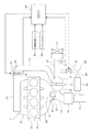
まず、図1に基づいて過給機付きエンジン制御システムの構成を概略的に説明する。
内燃機関であるエンジン11の吸気管12(吸気通路)の最上流部には、エアクリーナ13が設けられ、このエアクリーナ13の下流側に、吸入空気量を検出するエアフローメータ14が設けられている。一方、エンジン11の排気管15(排気通路)には、排出ガス中のCO,HC,NOx等を浄化する三元触媒等の触媒16が設置されている。
A first embodiment of the present invention will be described with reference to FIGS.
First, the configuration of the engine control system with a supercharger will be schematically described with reference to FIG.
An
このエンジン11には、吸入空気を過給する排気タービン駆動式の過給機17が搭載されている。この過給機17は、排気管15のうちの触媒16の上流側に排気タービン18が配置され、吸気管12のうちのエアフローメータ14の下流側にコンプレッサ19が配置されている。この過給機17は、排気タービン18とコンプレッサ19とが一体的に回転するように連結され、排出ガスの運動エネルギで排気タービン18を回転駆動することでコンプレッサ19を回転駆動して吸入空気を過給するようになっている。
The
吸気管12のうちのコンプレッサ19の下流側には、モータ20によって開度調節されるスロットルバルブ21と、このスロットルバルブ21の開度(スロットル開度)を検出するスロットル開度センサ22とが設けられている。
A
更に、スロットルバルブ21の下流側には、吸入空気を冷却するインタークーラ23(吸入空気冷却手段)が設けられている。このインタークーラ23の下流側に、エンジン11の各気筒に空気を導入する吸気マニホールド24が設けられ、各気筒毎に吸気ポート噴射又は筒内噴射を行う燃料噴射弁(図示せず)が取り付けられている。エンジン11のシリンダヘッドには、各気筒毎に点火プラグ(図示せず)が取り付けられ、各点火プラグの火花放電によって各気筒内の混合気に着火される。
Further, an intercooler 23 (intake air cooling means) for cooling the intake air is provided on the downstream side of the
エンジン11の各気筒の排気口には排気マニホールド25が接続され、各気筒の排気マニホールド25の下流側の集合部が排気タービン18の上流側の排気管15に接続されている。また、排気タービン18の上流側と下流側とをバイパスさせる排気バイパス通路26が設けられ、この排気バイパス通路26に、排気バイパス通路26を開閉するウェイストゲートバルブ(以下「WGV」と表記する)27が設けられている。
An
このエンジン11には、排気管15から排出ガスの一部をEGRガスとして吸気管12へ還流させるLPL方式(低圧ループ方式)のEGR装置28が搭載されている。このEGR装置28は、排気管15のうちの触媒16の下流側と吸気管12のうちのコンプレッサ19の上流側との間にEGR配管29が接続され、このEGR配管29に、EGRガスを冷却するEGRクーラ30(EGRガス冷却手段)と、EGRガス流量を制御するEGR弁31が設けられている。このEGR弁31は、モータ等のアクチュエータ(図示せず)によって開度が調整され、EGR弁31を開弁することで排気管15のうちの触媒16の下流側から吸気管12のうちのコンプレッサ19の上流側へEGRガスを還流させるようになっている。
The
また、エンジン11には、吸気バルブ(図示せず)のバルブタイミング(開閉タイミング)を変化させる吸気側可変バルブタイミング機構32と、排気バルブ(図示せず)のバルブタイミングを変化させる排気側可変バルブタイミング機構33が設けられている。その他、エンジン11には、冷却水温を検出する冷却水温センサ34や、クランク軸(図示せず)が所定クランク角回転する毎にパルス信号を出力するクランク角センサ35等が設けられ、クランク角センサ35の出力信号に基づいてクランク角やエンジン回転速度が検出される。
The
これら各種センサの出力は、電子制御ユニット(以下「ECU」と表記する)36に入力される。このECU36は、マイクロコンピュータを主体として構成され、内蔵されたROM(記憶媒体)に記憶された各種のエンジン制御用のプログラムを実行することで、エンジン運転状態に応じて、燃料噴射量、点火時期、スロットル開度(吸入空気量)等を制御する。
Outputs of these various sensors are input to an electronic control unit (hereinafter referred to as “ECU”) 36. The
また、ECU36は、エンジン運転状態(例えばエンジン負荷とエンジン回転速度等)に応じて目標EGR率を算出し、この目標EGR率を実現するようにEGR弁31の開度を制御する。
Further, the
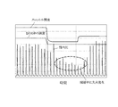
しかし、図2に示すように、EGR装置28を搭載したエンジン11は、減速時にスロットル開度を閉じ側に制御したときに、EGR弁30を閉弁するようにしても、スロットルバルブ21の上流側の吸気管12内にEGRガスが滞留して、EGRガスが過剰に多い状態となるため、そのままでは失火が発生し易くなるという問題がある。
However, as shown in FIG. 2, the
この対策として、本実施例1では、ECU36により後述する図3の減速時失火防止制御ルーチンを実行することで、エンジン11の減速時に排気圧を低下させる排気圧低下制御(例えばWGV27を開弁させる制御)を実行する。減速時に排気圧低下制御を実行して排気圧を低下させれば、内部EGRガス(気筒内に残留する燃焼ガス)の排気を促進して、内部EGRガス量を減少させることができる。これにより、減速時に吸気管12内に滞留する外部EGRガス(EGR装置28により還流されたEGRガス)が過剰に多い状態であっても、気筒内に充填される総EGRガス量(外部EGRガス量+内部EGRガス量)の増加を抑制するか又は気筒内に充填される総EGRガス量を減少させて、EGRガスによる減速時の失火を防止する。
As a countermeasure against this, in the first embodiment, the
以下、本実施例1でECU36が実行する図3の減速時失火防止制御ルーチンの処理内容を説明する。
図3に示す減速時失火防止制御ルーチンは、ECU36の電源オン期間中(イグニッションスイッチのオン期間中)に所定周期で繰り返し実行され、特許請求の範囲でいう制御手段としての役割を果たす。本ルーチンが起動されると、まず、ステップ101で、減速中であるか否かを、例えば、アクセルオフ(アクセル開度=0)であるか否か等によって判定する。
The processing contents of the deceleration misfire prevention control routine of FIG. 3 executed by the
The deceleration misfire prevention control routine shown in FIG. 3 is repeatedly executed at a predetermined cycle during the power-on period of the ECU 36 (while the ignition switch is on), and serves as a control means in the claims. When this routine is started, first, in
このステップ101で、減速中ではないと判定された場合には、ステップ102に進み、エンジン運転状態(例えばエンジン負荷とエンジン回転速度等)に応じて目標EGR率をマップ等により算出した後、ステップ103に進み、目標EGR率を実現するようにEGR弁31の開度を制御する。
If it is determined in
一方、上記ステップ101で、減速中であると判定された場合には、ステップ104に進み、目標EGR率を「0」に設定した後、ステップ105に進み、目標EGR率を実現するようにEGR弁31の開度を制御する(EGR弁31を閉弁する)。
On the other hand, if it is determined in
この後、ステップ106に進み、EGRガスによる減速時の失火を防止するために、排気圧を低下させる排気圧低下制御を実行する。この排気圧低下制御として、例えば、WGV27を開弁させる制御を実行する。WGV27を開弁させれば、排気タービン18をバイパスして流れる排出ガス量を増加させて、排気圧を低下させることができ、内部EGRガスの排気を促進することができる。
Thereafter, the routine proceeds to step 106, where exhaust pressure lowering control for lowering the exhaust pressure is executed in order to prevent misfire during deceleration due to EGR gas. As this exhaust pressure reduction control, for example, control for opening the
尚、排気圧低下制御は、WGV27を開弁させる制御に限定されず、適宜変更しても良く、例えば、排気圧低下制御として、排気側可変バルブタイミング機構33により排気バルブの閉弁時期を上死点から遠ざかるよう進角する制御を実行するようにしても良い。また、排気バルブのリフト量や作用角を変化させる排気側可変バルブ機構を備えたシステムでは、排気圧低下制御として、排気側可変バルブ機構により排気バルブのリフト量を増加させる制御や排気バルブの作用角を広くする制御を実行するようにしても良い。このようにすれば、気筒内から排気バルブのバルブ開口部を通して排出ガスが排出される際の圧損を小さくして、排気圧を低下させることができ、内部EGRガスの排気を促進することができる。
The exhaust pressure lowering control is not limited to the control for opening the
以上説明した本実施例1では、エンジン11の減速時に排気圧を低下させる排気圧低下制御(例えばWGV27を開弁させる制御)を実行するようにしたので、内部EGRガスの排気を促進して、内部EGRガス量を減少させることができ、これにより、減速時に吸気管12内に滞留する外部EGRガスが過剰に多い状態であっても、気筒内に充填される総EGRガス量(外部EGRガス量+内部EGRガス量)の増加を抑制するか又は気筒内に充填される総EGRガス量を減少させることができ、燃料カット制御を実施できない状況でもEGRガスによる減速時の失火を防止することができる。
In the first embodiment described above, exhaust pressure lowering control (for example, control for opening WWGV 27) for reducing the exhaust pressure when the
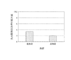
図4に示すように、本発明者らの実験結果によると、減速時に排気圧低下制御(例えばWGV27を開弁させる制御)を実行することにより、低負荷運転時には失火限界EGR率(失火が発生しないEGR率の上限値)を約3%拡大でき、高負荷運転時には失火限界EGR率を約2%拡大できることが確認された。 As shown in FIG. 4, according to the experimental results of the present inventors, by performing exhaust pressure reduction control (for example, control for opening the WGV 27) during deceleration, a misfire limit EGR rate (misfire occurs during low load operation). It was confirmed that the upper limit value of the EGR rate not to be increased) can be increased by about 3%, and the misfire limit EGR rate can be increased by about 2% during high-load operation.
次に、図5を用いて本発明の実施例2を説明する。但し、前記実施例1と実質的に同一部分については説明を省略又は簡略化し、主として前記実施例1と異なる部分について説明する。 Next, Embodiment 2 of the present invention will be described with reference to FIG. However, description of substantially the same parts as those in the first embodiment will be omitted or simplified, and different parts from the first embodiment will be mainly described.
本実施例2では、ECU36により後述する図5の減速時失火防止制御ルーチンを実行することで、エンジン11の減速時に吸気管12内のEGRガスが吸入空気に交換される速度(EGRガスが吸入空気に入れ替わる速度)を上昇させる交換速度上昇制御(例えばインタークーラ23の冷却能力を高める制御)を実行する。減速時に交換速度上昇制御を実行して吸気管12内のEGRガスが吸入空気に交換される速度を上昇させれば、吸気管12内に滞留するEGRガスの掃気を促進することができる。これにより、減速時に吸気管12内のEGRガスを速やかに減少させて、気筒内に充填されるEGRガス量を早期に減少させて、減速時の早期からEGRガスによる失火を防止する。
In the second embodiment, the
本実施例2で実行する図5のルーチンは、前記実施例1で説明した図3のルーチンのステップ106の処理を、ステップ106aの処理に変更したものであり、それ以外の各ステップの処理は図3と同じである。
The routine of FIG. 5 executed in the second embodiment is obtained by changing the process of
図5の減速時失火防止制御ルーチンでは、ステップ101で、減速中であると判定された場合には、目標EGR率を「0」に設定して、EGR弁31を閉弁する(ステップ104、105)。
In the deceleration misfire prevention control routine of FIG. 5, if it is determined in
この後、ステップ106aに進み、EGRガスによる減速時の失火を防止するために、吸気管12内のEGRガスが吸入空気に交換される速度を上昇させる交換速度上昇制御を実行する。この交換速度上昇制御として、例えば、吸入空気の目標温度を低下させてインタークーラ23の冷却能力を高める制御を実行する。インタークーラ23の冷却能力を高めれば、吸入空気の温度を低下させて吸入空気の体積を減少させることができ、その分、気筒内に吸入可能なEGRガス量を増加させて、吸気管12内のEGRガスが吸入空気に交換される速度を上昇させることができ、吸気管12内に滞留するEGRガスの掃気を促進することができる。
Thereafter, the process proceeds to step 106a, and exchange speed increase control for increasing the speed at which the EGR gas in the
尚、交換速度上昇制御は、インタークーラ23の冷却能力を高める制御に限定されず、適宜変更しても良く、例えば、交換速度上昇制御として、EGRクーラ30に循環させる冷却水量を増加させてEGRクーラ30の冷却能力を高める制御を実行するようにしても良い。EGRクーラ30の冷却能力を高めれば、EGRガスの温度を低下させてEGRガスの体積を減少させることができ、その分、気筒内に吸入可能なEGRガス量を増加させて、吸気管12内のEGRガスが吸入空気に交換される速度を上昇させることができ、吸気管12内に滞留するEGRガスの掃気を促進することができる。
The replacement speed increase control is not limited to the control for increasing the cooling capacity of the
或は、交換速度上昇制御として、シフトダウンしてエンジン回転速度を上昇させる制御を実行するようにしても良い。エンジン回転速度を上昇させれば、単位時間当りに気筒内に吸入可能なEGRガス量を増加させて、吸気管12内のEGRガスが吸入空気に交換される速度を上昇させることができ、吸気管12内に滞留するEGRガスの掃気を促進することができる。
Alternatively, as the replacement speed increase control, control for shifting down and increasing the engine rotation speed may be executed. If the engine speed is increased, the amount of EGR gas that can be sucked into the cylinder per unit time can be increased, and the speed at which the EGR gas in the
以上説明した本実施例2では、エンジン11の減速時に吸気管12内のEGRガスが吸入空気に交換される速度を上昇させる交換速度上昇制御(例えばインタークーラ23の冷却能力を高める制御)を実行するようにしたので、吸気管12内に滞留するEGRガスの掃気を促進することができ、これにより、減速時に吸気管12内のEGRガスを速やかに減少させて、気筒内に充填されるEGRガス量を早期に減少させることができ、燃料カット制御を実施できない状況でも減速時の早期からEGRガスによる失火を防止することができる。
In the second embodiment described above, exchange speed increase control (for example, control for increasing the cooling capacity of the intercooler 23) is executed to increase the speed at which the EGR gas in the
次に、図6を用いて本発明の実施例3を説明する。但し、前記実施例1と実質的に同一部分については説明を省略又は簡略化し、主として前記実施例1と異なる部分について説明する。 Next, Embodiment 3 of the present invention will be described with reference to FIG. However, description of substantially the same parts as those in the first embodiment will be omitted or simplified, and different parts from the first embodiment will be mainly described.
本実施例3では、ECU36により後述する図6の減速時失火防止制御ルーチンを実行することで、エンジン11の減速時に吸気抵抗を低下させる吸気抵抗低下制御(例えば吸気側可変バルブタイミング機構32により吸気バルブの開弁時期を上死点近傍へ進角する制御)を実行する。減速時に吸気抵抗低下制御を実行して吸気抵抗を低下させれば、吸入空気(新気)の導入を促進して、吸気管12内に滞留するEGRガスの掃気を促進することができる。これにより、減速時に吸気管12内のEGRガスを速やかに減少させて、気筒内に充填されるEGRガス量を早期に減少させて、減速時の早期からEGRガスによる失火を防止する。
In the present third embodiment, the
本実施例3で実行する図6のルーチンは、前記実施例1で説明した図3のルーチンのステップ106の処理を、ステップ106bの処理に変更したものであり、それ以外の各ステップの処理は図3と同じである。
The routine of FIG. 6 executed in the third embodiment is obtained by changing the process of
図6の減速時失火防止制御ルーチンでは、ステップ101で、減速中であると判定された場合には、目標EGR率を「0」に設定して、EGR弁31を閉弁する(ステップ104、105)。
In the deceleration misfire prevention control routine of FIG. 6, if it is determined in
この後、ステップ106bに進み、EGRガスによる減速時の失火を防止するために、吸気抵抗を低下させる吸気抵抗低下制御を実行する。この吸気抵抗低下制御として、例えば、吸気側可変バルブタイミング機構32により吸気バルブの開弁時期を上死点近傍へ進角する制御を実行する。このようにすれば、吸気バルブのバルブ開口部を通して気筒内へ吸入空気が吸入される際の吸気抵抗を低下させることができ、これにより、吸入空気(新気)の導入を促進して、吸気管12内に滞留するEGRガスの掃気を促進することができる。
Thereafter, the process proceeds to step 106b, and intake resistance lowering control for reducing the intake resistance is executed in order to prevent misfire during deceleration by EGR gas. As the intake resistance lowering control, for example, the intake side variable
尚、吸気抵抗低下制御は、吸気側可変バルブタイミング機構32により吸気バルブの開弁時期を上死点近傍へ進角する制御に限定されず、適宜変更しても良く、例えば、吸気バルブのリフト量や作用角を変化させる吸気側可変バルブ機構を備えたシステムでは、吸気抵抗低下制御として、吸気側可変バルブ機構により吸気バルブのリフト量を増加させる制御や吸気バルブの作用角を広くする制御を実行するようにしても良い。このようにしても、吸気バルブのバルブ開口部を通して気筒内へ吸入空気が吸入される際の吸気抵抗を低下させることができ、これにより、吸入空気(新気)の導入を促進して、吸気管12内に滞留するEGRガスの掃気を促進することができる。
The intake resistance lowering control is not limited to the control for advancing the opening timing of the intake valve to near the top dead center by the intake side variable
以上説明した本実施例3では、エンジン11の減速時に吸気抵抗を低下させる吸気抵抗低下制御(例えば吸気側可変バルブタイミング機構32により吸気バルブの開弁時期を上死点近傍へ進角する制御)を実行するようにしたので、吸入空気(新気)の導入を促進して、吸気管12内に滞留するEGRガスの掃気を促進することができ、これにより、減速時に吸気管12内のEGRガスを速やかに減少させて、気筒内に充填されるEGRガス量を早期に減少させることができ、燃料カット制御を実施できない状況でも減速時の早期からEGRガスによる失火を防止することができる。
In the third embodiment described above, intake resistance reduction control for reducing the intake resistance when the
次に、図7を用いて本発明の実施例4を説明する。但し、前記実施例1と実質的に同一部分については説明を省略又は簡略化し、主として前記実施例1と異なる部分について説明する。 Next, Embodiment 4 of the present invention will be described with reference to FIG. However, description of substantially the same parts as those in the first embodiment will be omitted or simplified, and different parts from the first embodiment will be mainly described.
本実施例4では、エンジン11に、図示しない電動式の過給機(例えば、電動式のターボチャージャ)が搭載されている。そして、ECU36により後述する図7の減速時失火防止制御ルーチンを実行することで、エンジン11の減速時に吸気管12へ強制的に新気(空気)を導入する新気導入制御(例えば電動式の過給機により吸入空気を過給する制御)を実行する。減速時に新気導入制御を実行して強制的に新気を導入すれば、強制的に導入した新気によって、吸気管12内に滞留するEGRガスの掃気を促進することができる。これにより、減速時に吸気管12内のEGRガスを速やかに減少させて、気筒内に充填されるEGRガス量を早期に減少させて、減速時の早期からEGRガスによる失火を防止する。
In the fourth embodiment, the
本実施例4で実行する図7のルーチンは、前記実施例1で説明した図3のルーチンのステップ106の処理を、ステップ110〜112の処理に変更したものであり、それ以外の各ステップの処理は図3と同じである。
The routine of FIG. 7 executed in the fourth embodiment is obtained by changing the process of
図7の減速時失火防止制御ルーチンでは、ステップ101で、減速中であると判定された場合には、目標EGR率を「0」に設定して、EGR弁31を閉弁する(ステップ104、105)。
In the deceleration misfire prevention control routine of FIG. 7, when it is determined in
この後、ステップ110に進み、減速開始から所定時間(例えば1sec)以内であるか否かを判定し、減速開始から所定時間以内であると判定されれば、ステップ111に進み、吸気側可変バブルタイミング機構32により吸気バルブの開弁時期がTDC(上死点)よりも進角側になるように吸気バルブのバルブタイミングを進角させると共に、排気側可変バブルタイミング機構33により排気バルブの閉弁時期がTDCよりも遅角側になるように排気バルブのバルブタイミングを遅角させて、吸気バルブと排気バルブの両方が開弁した状態となるバルブオーバーラップ期間を設定する。尚、吸気バルブと排気バルブのうちの一方のバルブタイミングのみを制御してバルブオーバーラップ期間を設定するようにしても良い。
Thereafter, the process proceeds to step 110, where it is determined whether or not it is within a predetermined time (for example, 1 sec) from the start of deceleration. If it is determined that it is within the predetermined time from the start of deceleration, the process proceeds to step 111 and the intake side variable bubble is determined. The
この後、ステップ112に進み、EGRガスによる減速時の失火を防止するために、バルブオーバーラップ期間を設けた状態で、吸気管12へ強制的に新気(空気)を導入する新気導入制御を実行する。この新気導入制御として、例えば、電動式の過給機のモータ回転速度を上昇させて電動式の過給機により吸入空気(新気)を過給する制御を実行する。このようにすれば、過給機により吸気管12へ強制的に吸入空気(新気)を導入することができ、吸気管12内に滞留するEGRガスの掃気を促進することができる。
Thereafter, the process proceeds to step 112, and fresh air introduction control for forcibly introducing fresh air (air) into the
尚、新気導入制御は、電動式の過給機により吸入空気を過給する制御に限定されず、適宜変更しても良く、例えば、吸気管12へ外気を導入する外気導入装置を備えたシステムでは、新気導入制御として、外気導入装置により吸気管12へ外気(新気)を導入する制御を実行するようにしても良い。ここで、外気導入装置としては、例えば、外気を導入する機能を備えた燃料噴射弁(エアブラスト・インジェクション)を用いることができる。このようにすれば、外気導入装置により吸気管12へ強制的に外気(新気)を導入することができ、吸気管12内に滞留するEGRガスの掃気を促進することができる。
The fresh air introduction control is not limited to the control of supercharging the intake air by the electric supercharger, and may be changed as appropriate. For example, the outside air introduction device for introducing the outside air into the
この後、上記ステップ110で、減速開始から所定時間以内ではない(減速開始から所定時間以上が経過した)と判定された時点で、吸気バルブや排気バルブのバルブタイミングをエンジン運転状態に応じた通常位置に戻すと共に、新気導入制御を停止して、減速感が鈍ることを防止する。
After that, when it is determined in
以上説明した本実施例4では、エンジン11の減速時に吸気管12へ強制的に新気(空気)を導入する新気導入制御(例えば電動式の過給機により吸入空気を過給する制御)を実行するようにしたので、強制的に導入した新気によって、吸気管12内に滞留するEGRガスの掃気を促進することができ、これにより、減速時に吸気管12内のEGRガスを速やかに減少させて、気筒内に充填されるEGRガス量を早期に減少させることができ、燃料カット制御を実施できない状況でも減速時の早期からEGRガスによる失火を防止することができる。
In the fourth embodiment described above, fresh air introduction control for forcibly introducing fresh air (air) into the
しかも、本実施例4では、吸気バルブと排気バルブの両方が開弁した状態となるバルブオーバーラップ期間を設けた状態で新気導入制御を実行するようにしたので、強制的に導入した新気によって、バルブオーバーラップ期間中に吸気管12内のEGRガスを気筒内を通過させて排気管12へ排出することができ、EGRガスの掃気を更に促進することができる。
Moreover, in the fourth embodiment, the fresh air introduction control is executed in a state where the valve overlap period in which both the intake valve and the exhaust valve are opened is provided. Thus, during the valve overlap period, the EGR gas in the
尚、上記各実施例1〜4では、排気管15のうちの触媒16の下流側から吸気管12のうちのコンプレッサ19の上流側へEGRガスを還流させる低圧ループ方式(LPL方式)のEGR装置を採用した過給機付きエンジンに本発明を適用したので、LPL方式のEGR装置を採用した過給機付きエンジンにおいて、EGRガスによる減速時の失火を防止することができる。
In the first to fourth embodiments, a low-pressure loop type (LPL type) EGR device that recirculates EGR gas from the downstream side of the
しかしながら、本発明は、LPL方式のEGR装置を採用した過給機付きエンジンに限定されず、排気管のうちの排気タービンの上流側から吸気管のうちのスロットルバルブの下流側へEGRガスを還流させる高圧ループ方式(HPL方式)のEGR装置を採用した過給機付きエンジンに適用しても良く、このようにすれば、HPL方式のEGR装置を採用した過給機付きエンジンにおいて、EGRガスによる減速時の失火を防止することができる。 However, the present invention is not limited to an engine with a supercharger that employs an LPL type EGR device, and recirculates EGR gas from the upstream side of the exhaust turbine in the exhaust pipe to the downstream side of the throttle valve in the intake pipe. It may be applied to an engine with a supercharger that uses an EGR device of a high-pressure loop method (HPL method), and in this way, in an engine with a supercharger that uses an HPL method of EGR, Misfire during deceleration can be prevented.
更に、本発明は、排気タービン駆動式の過給機(いわゆるターボチャージャ)を搭載したエンジンに限定されず、機械駆動式の過給機(いわゆるスーパーチャージャ)や電動式の過給機(例えば、電動式のターボチャージャや電動式のスーパーチャージャ)を搭載したエンジンに適用しても良い。 Furthermore, the present invention is not limited to an engine equipped with an exhaust turbine-driven supercharger (so-called turbocharger), but a machine-driven supercharger (so-called supercharger) or an electric supercharger (for example, The present invention may be applied to an engine equipped with an electric turbocharger or an electric supercharger.
その他、本発明は、過給機付きエンジンに限定されず、過給機を搭載していない自然吸気エンジン(NAエンジン)に適用しても良く、この場合、排気管のうちの触媒の上流側又は下流側から吸気管のうちのスロットルバルブの下流側へEGRガスを還流させるEGR装置を採用した自然吸気エンジンに適用しても良い。 In addition, the present invention is not limited to an engine with a supercharger, and may be applied to a naturally aspirated engine (NA engine) not equipped with a supercharger. In this case, the upstream side of the catalyst in the exhaust pipe Alternatively, the present invention may be applied to a naturally aspirated engine that employs an EGR device that recirculates EGR gas from the downstream side to the downstream side of the throttle valve in the intake pipe.
11…エンジン(内燃機関)、12…吸気管(吸気通路)、15…排気管(排気通路)、16…触媒、17…過給機、18…排気タービン、19…コンプレッサ、21…スロットルバルブ、23…インタークーラ(吸入空気冷却手段)、26…排気バイパス通路、27…WGV、28…EGR装置、29…EGR配管、30…EGRクーラ(EGRガス冷却手段)、31…EGR弁31、32…吸気側可変バルブタイミング機構、33…排気側可変バルブタイミング機構、36…ECU(制御手段)
DESCRIPTION OF
Claims (15)
前記内燃機関の減速時に排気圧を低下させる排気圧低下制御を実行する制御手段を備えていることを特徴とする内燃機関の制御装置。 In a control device for an internal combustion engine provided with an EGR device that recirculates a part of exhaust gas from an exhaust passage of the internal combustion engine to an intake passage as EGR gas,
A control device for an internal combustion engine, comprising control means for executing exhaust pressure reduction control for reducing the exhaust pressure when the internal combustion engine is decelerated.
前記制御手段は、前記減速時に前記ウェイストゲートバルブを開弁させることで前記排気圧低下制御を実行することを特徴とする請求項1に記載の内燃機関の制御装置。 A turbocharger that supercharges intake air by driving a compressor provided in the intake passage with an exhaust turbine provided in the exhaust passage, and a waste gate valve that opens and closes an exhaust bypass passage that bypasses the exhaust turbine. Prepared,
2. The control apparatus for an internal combustion engine according to claim 1, wherein the control means executes the exhaust pressure reduction control by opening the waste gate valve during the deceleration.
前記制御手段は、前記減速時に前記可変バブル機構により前記排気バルブのバルブ開閉特性を排気圧の低下方向に変化させることで前記排気圧低下制御を実行することを特徴とする請求項1又は2に記載の内燃機関の制御装置。 A variable bubble mechanism for changing a valve opening / closing characteristic of an exhaust valve of the internal combustion engine,
The said control means performs the said exhaust pressure fall control by changing the valve opening / closing characteristic of the said exhaust valve to the fall direction of exhaust pressure by the said variable bubble mechanism at the time of the said deceleration. The internal combustion engine control device described.
前記内燃機関の減速時に前記吸気通路内のEGRガスが吸入空気に交換される速度を上昇させる交換速度上昇制御を実行する制御手段を備えていることを特徴とする内燃機関の制御装置。 In a control device for an internal combustion engine provided with an EGR device that recirculates a part of exhaust gas from an exhaust passage of the internal combustion engine to an intake passage as EGR gas,
A control apparatus for an internal combustion engine, comprising control means for executing exchange speed increase control for increasing a speed at which EGR gas in the intake passage is exchanged with intake air when the internal combustion engine is decelerated.
前記制御手段は、前記減速時に前記吸入空気冷却手段の冷却能力を高めることで前記交換速度上昇制御を実行することを特徴とする請求項4に記載の内燃機関の制御装置。 Intake air cooling means for cooling the intake air of the internal combustion engine,
5. The control apparatus for an internal combustion engine according to claim 4, wherein the control means executes the replacement speed increase control by increasing a cooling capacity of the intake air cooling means during the deceleration.
前記制御手段は、前記減速時に前記EGRガス冷却手段の冷却能力を高めることで前記交換速度上昇制御を実行することを特徴とする請求項4又は5に記載の内燃機関の制御装置。 EGR gas cooling means for cooling the EGR gas,
6. The control device for an internal combustion engine according to claim 4, wherein the control unit executes the replacement speed increase control by increasing a cooling capacity of the EGR gas cooling unit during the deceleration.
前記内燃機関の減速時に吸気抵抗を低下させる吸気抵抗低下制御を実行する制御手段を備えていることを特徴とする内燃機関の制御装置。 In a control device for an internal combustion engine provided with an EGR device that recirculates a part of exhaust gas from an exhaust passage of the internal combustion engine to an intake passage as EGR gas,
A control device for an internal combustion engine, comprising control means for performing intake resistance reduction control for reducing intake resistance during deceleration of the internal combustion engine.
前記制御手段は、前記減速時に前記可変バブル機構により前記吸気バルブのバルブ開閉特性を吸気抵抗の低下方向に変化させることで前記吸気抵抗低下制御を実行することを特徴とする請求項8に記載の内燃機関の制御装置。 A variable bubble mechanism for changing the valve opening and closing characteristics of the intake valve of the internal combustion engine,
The said control means performs the said intake resistance fall control by changing the valve opening / closing characteristic of the said intake valve to the fall direction of an intake resistance by the said variable bubble mechanism at the time of the said deceleration. Control device for internal combustion engine.
前記内燃機関の減速時に前記吸気通路へ強制的に新気を導入する新気導入制御を実行する制御手段を備えていることを特徴とする内燃機関の制御装置。 In a control device for an internal combustion engine provided with an EGR device that recirculates a part of exhaust gas from an exhaust passage of the internal combustion engine to an intake passage as EGR gas,
A control device for an internal combustion engine, comprising: control means for executing fresh air introduction control for forcibly introducing fresh air into the intake passage during deceleration of the internal combustion engine.
前記制御手段は、前記減速時に前記過給機により吸入空気を過給することで前記新気導入制御を実行することを特徴とする請求項10に記載の内燃機関の制御装置。 A supercharger for supercharging intake air of the internal combustion engine;
11. The control apparatus for an internal combustion engine according to claim 10, wherein the control means executes the fresh air introduction control by supercharging intake air by the supercharger during the deceleration.
前記制御手段は、前記減速時に前記外気導入装置により前記吸気通路へ外気を導入することで前記新気導入制御を実行することを特徴とする請求項10又は11に記載の内燃機関の制御装置。 An outside air introduction device for introducing outside air into the intake passage;
The control device for an internal combustion engine according to claim 10 or 11, wherein the control means executes the fresh air introduction control by introducing outside air into the intake passage by the outside air introduction device during the deceleration.
前記制御手段は、前記減速時に前記可変バブル機構により前記吸気バルブと前記排気バルブの両方が開弁した状態となるバルブオーバーラップ期間を設けた状態で前記新気導入制御を実行することを特徴とする請求項10乃至12のいずれかに記載の内燃機関の制御装置。 A variable bubble mechanism that changes a valve opening / closing characteristic of at least one of an intake valve and an exhaust valve of the internal combustion engine,
The control means performs the fresh air introduction control in a state in which a valve overlap period is set in which both the intake valve and the exhaust valve are opened by the variable bubble mechanism during the deceleration. The control device for an internal combustion engine according to any one of claims 10 to 12.
前記EGR装置は、前記排気通路のうちの前記排気タービンの下流側に設けられた排出ガス浄化用の触媒の下流側から前記吸気通路のうちの前記コンプレッサの上流側へEGRガスを還流させる低圧ループ方式のEGR装置であることを特徴とする請求項1乃至13のいずれかに記載の内燃機関の制御装置。 A supercharger for supercharging intake air by driving a compressor provided in the intake passage by an exhaust turbine provided in the exhaust passage;
The EGR device is a low-pressure loop that recirculates EGR gas from a downstream side of an exhaust gas purifying catalyst provided downstream of the exhaust turbine in the exhaust passage to an upstream side of the compressor in the intake passage. 14. The internal combustion engine control device according to claim 1, wherein the control device is an EGR device of a type.
前記EGR装置は、前記排気通路のうちの前記排気タービンの上流側から前記吸気通路のうちのスロットルバルブの下流側へEGRガスを還流させる高圧ループ方式のEGR装置であることを特徴とする請求項1乃至13のいずれかに記載の内燃機関の制御装置。 A supercharger for supercharging intake air by driving a compressor provided in the intake passage by an exhaust turbine provided in the exhaust passage;
The EGR device is a high-pressure loop type EGR device that recirculates EGR gas from an upstream side of the exhaust turbine in the exhaust passage to a downstream side of a throttle valve in the intake passage. The control apparatus for an internal combustion engine according to any one of 1 to 13.
Priority Applications (1)
| Application Number | Priority Date | Filing Date | Title |
|---|---|---|---|
| JP2011029186A JP2012167601A (en) | 2011-02-14 | 2011-02-14 | Control device of internal combustion engine |
Applications Claiming Priority (1)
| Application Number | Priority Date | Filing Date | Title |
|---|---|---|---|
| JP2011029186A JP2012167601A (en) | 2011-02-14 | 2011-02-14 | Control device of internal combustion engine |
Related Child Applications (1)
| Application Number | Title | Priority Date | Filing Date |
|---|---|---|---|
| JP2014013827A Division JP2014101886A (en) | 2014-01-28 | 2014-01-28 | Control device of internal combustion engine |
Publications (1)
| Publication Number | Publication Date |
|---|---|
| JP2012167601A true JP2012167601A (en) | 2012-09-06 |
Family
ID=46971978
Family Applications (1)
| Application Number | Title | Priority Date | Filing Date |
|---|---|---|---|
| JP2011029186A Pending JP2012167601A (en) | 2011-02-14 | 2011-02-14 | Control device of internal combustion engine |
Country Status (1)
| Country | Link |
|---|---|
| JP (1) | JP2012167601A (en) |
Cited By (3)
| Publication number | Priority date | Publication date | Assignee | Title |
|---|---|---|---|---|
| JP2015078627A (en) * | 2013-10-16 | 2015-04-23 | ダイハツ工業株式会社 | Control device of internal combustion engine |
| US9803612B2 (en) | 2013-04-17 | 2017-10-31 | Denso Corporation | Control device for internal combustion engine |
| JP2017223179A (en) * | 2016-06-16 | 2017-12-21 | トヨタ自動車株式会社 | Control device of internal combustion engine |
Citations (3)
| Publication number | Priority date | Publication date | Assignee | Title |
|---|---|---|---|---|
| JP2009156055A (en) * | 2007-12-25 | 2009-07-16 | Toyota Motor Corp | Exhaust control device for internal combustion engine |
| JP2010174859A (en) * | 2009-02-02 | 2010-08-12 | Toyota Motor Corp | Control device of internal combustion engine with supercharger |
| JP2010249002A (en) * | 2009-04-15 | 2010-11-04 | Toyota Motor Corp | Control system for internal combustion engine |
-
2011
- 2011-02-14 JP JP2011029186A patent/JP2012167601A/en active Pending
Patent Citations (3)
| Publication number | Priority date | Publication date | Assignee | Title |
|---|---|---|---|---|
| JP2009156055A (en) * | 2007-12-25 | 2009-07-16 | Toyota Motor Corp | Exhaust control device for internal combustion engine |
| JP2010174859A (en) * | 2009-02-02 | 2010-08-12 | Toyota Motor Corp | Control device of internal combustion engine with supercharger |
| JP2010249002A (en) * | 2009-04-15 | 2010-11-04 | Toyota Motor Corp | Control system for internal combustion engine |
Cited By (3)
| Publication number | Priority date | Publication date | Assignee | Title |
|---|---|---|---|---|
| US9803612B2 (en) | 2013-04-17 | 2017-10-31 | Denso Corporation | Control device for internal combustion engine |
| JP2015078627A (en) * | 2013-10-16 | 2015-04-23 | ダイハツ工業株式会社 | Control device of internal combustion engine |
| JP2017223179A (en) * | 2016-06-16 | 2017-12-21 | トヨタ自動車株式会社 | Control device of internal combustion engine |
Similar Documents
| Publication | Publication Date | Title |
|---|---|---|
| CN103958861B (en) | The control device of internal combustion engine | |
| JP4517515B2 (en) | 4-cycle engine for automobiles | |
| US8201406B2 (en) | Control apparatus for internal combustion engine | |
| JP4816812B2 (en) | Control device for internal combustion engine | |
| JP5579023B2 (en) | Internal combustion engine | |
| JP5610873B2 (en) | Internal combustion engine | |
| JP2014169644A (en) | Control device for internal combustion engine | |
| JP5092962B2 (en) | Control device for an internal combustion engine with a supercharger | |
| JP5348338B2 (en) | Engine control device | |
| JP2009235920A (en) | Fuel injection control device of cylinder injection internal combustion engine with supercharger | |
| JP2014034959A (en) | Exhaust gas recirculation device of engine with supercharger | |
| JP2009019611A (en) | Control device for an internal combustion engine with a supercharger | |
| JP5126424B1 (en) | Control device for internal combustion engine | |
| JP2012097639A (en) | Control device for internal combustion engine | |
| JP2012167601A (en) | Control device of internal combustion engine | |
| JP5924254B2 (en) | Turbocharged engine | |
| JP6127906B2 (en) | Control device for internal combustion engine | |
| JP2009299623A (en) | Control device for internal combustion engine | |
| JP2013130121A (en) | Exhaust gas recirculation system for spark-ignition-type internal combustion engine | |
| JP2014190264A (en) | Device for controlling internal combustion engine | |
| JP2011241713A (en) | Control device of internal combustion engine | |
| JP5338709B2 (en) | Control device for internal combustion engine | |
| JP2014101886A (en) | Control device of internal combustion engine | |
| JP2014231821A (en) | Controller for internal combustion engine equipped with supercharger | |
| JP2014080897A (en) | Engine with turbo supercharger |
Legal Events
| Date | Code | Title | Description |
|---|---|---|---|
| A621 | Written request for application examination |
Free format text: JAPANESE INTERMEDIATE CODE: A621 Effective date: 20130311 |
|
| A977 | Report on retrieval |
Free format text: JAPANESE INTERMEDIATE CODE: A971007 Effective date: 20131216 |
|
| A131 | Notification of reasons for refusal |
Free format text: JAPANESE INTERMEDIATE CODE: A131 Effective date: 20131218 |
|
| A02 | Decision of refusal |
Free format text: JAPANESE INTERMEDIATE CODE: A02 Effective date: 20140502 |