JP2012167724A - Vehicular disk brake - Google Patents
Vehicular disk brake Download PDFInfo
- Publication number
- JP2012167724A JP2012167724A JP2011028135A JP2011028135A JP2012167724A JP 2012167724 A JP2012167724 A JP 2012167724A JP 2011028135 A JP2011028135 A JP 2011028135A JP 2011028135 A JP2011028135 A JP 2011028135A JP 2012167724 A JP2012167724 A JP 2012167724A
- Authority
- JP
- Japan
- Prior art keywords
- hole
- claw
- friction pad
- reaction
- reaction force
- Prior art date
- Legal status (The legal status is an assumption and is not a legal conclusion. Google has not performed a legal analysis and makes no representation as to the accuracy of the status listed.)
- Granted
Links
Images


Landscapes
- Braking Arrangements (AREA)
Abstract
【課題】反力爪の偏摩耗を防止し、キャリパボディの耐久力を向上させると共に、コストの低減化を図る。
【解決手段】シリンダ孔7を有する作用部5aと、一対の反力爪5i,5iを有し、隣接する反力爪間にシリンダ孔切削用通孔5hを有する反作用部5bとをディスクロータ2の外周を跨ぐブリッジ部5cで連結してキャリパボディ5を形成する。作用部5aと反作用部5bとの間に、ディスクロータ2を挟んで一対の摩擦パッド6,6を配置する。反力爪5i,5iのディスクロータ側面5kに、反作用部側の摩擦パッド6を押圧する補強プレート10を着脱可能に装着する。
【選択図】図1An object of the present invention is to prevent uneven wear of a reaction force claw, improve the durability of a caliper body, and reduce the cost.
A disk rotor includes an action portion having a cylinder hole and a reaction portion having a pair of reaction force claws and a cylinder hole cutting hole between adjacent reaction force claws. The caliper body 5 is formed by connecting with a bridge portion 5c straddling the outer periphery of the caliper. A pair of friction pads 6 and 6 are disposed between the action portion 5a and the reaction portion 5b with the disk rotor 2 interposed therebetween. A reinforcing plate 10 that presses the friction pad 6 on the reaction portion side is detachably attached to the disk rotor side surface 5k of the reaction force claws 5i, 5i.
[Selection] Figure 1
Description
本発明は、車両用ディスクブレーキに関し、詳しくは、シリンダ孔を有する作用部と、シリンダ孔切削用通孔の両側に形成される反力爪を有する反作用部とをブリッジ部で連結してキャリパボディを形成したピンスライド型の車両用ディスクブレーキに関する。 The present invention relates to a disk brake for a vehicle, and more specifically, a caliper body in which an action part having a cylinder hole and a reaction part having reaction force claws formed on both sides of a cylinder hole cutting through hole are connected by a bridge part. The present invention relates to a pin slide type disk brake for vehicles.
ピンスライド型の車両用ディスクブレーキでは、シリンダ孔を有する作用部と、シリンダ孔切削用通孔の両側に形成される反力爪を有する反作用部とをブリッジ部で連結してキャリパボディが形成されており、制動時には、昇圧した作動液によりピストンがシリンダ孔を前進し、作用部側の摩擦パッドを、ディスクロータの一側面に押圧すると共に、この反力によって、キャリパボディがスライドピンに案内されながら、作用部方向へ移動し、反力爪が反作用部側の摩擦パッドをディスクロータの他側面へ押圧する(例えば、特許文献1参照。)。 In a pin slide type vehicle disc brake, a caliper body is formed by connecting an action part having a cylinder hole and a reaction part having reaction force claws formed on both sides of a cylinder hole cutting through hole at a bridge part. During braking, the piston moves forward through the cylinder hole by the pressurized hydraulic fluid, and the friction pad on the working side is pressed against one side of the disk rotor, and this reaction force guides the caliper body to the slide pin. While moving in the direction of the action part, the reaction force claw presses the friction pad on the reaction part side against the other side of the disk rotor (for example, see Patent Document 1).
しかし、上述のような多くのピンスライド型の車両用ディスクブレーキでは、反力爪はシリンダ孔切削用通孔を挟んで形成されるため、爪のパッド当接面積が小さくなってしまい、ピストンからの推力を小さい面積で受けなければならないと共に、振動の影響も受けることから反力爪が摩耗する虞があり、摩耗が進むと反作用部側の摩擦パッドを適正な状態でディスクロータへ押圧できないことがあった。さらに、反力爪の摩耗が進んだ際には、キャリパボディ全体を交換しなくてはならないことからコストが嵩んでいた。 However, in many pin slide type vehicle disc brakes as described above, the reaction force claw is formed with the cylinder hole cutting through hole interposed therebetween. The thrust of the reaction force must be received in a small area and the reaction force claw may be worn due to the influence of vibration, and if the wear progresses, the friction pad on the reaction part side cannot be pressed to the disc rotor in an appropriate state was there. Further, when the reaction force claws are worn, the entire caliper body must be replaced, which increases costs.
そこで本発明は、ピストンからの推力及び振動を低減できるように、反力爪のパッド当接面積を確保して、反力爪の摩耗を防止し、キャリパボディの耐久力を向上させると共に、コストの低減化を図ることのできる車両用ディスクブレーキを提供することを目的としている。 Accordingly, the present invention secures the pad contact area of the reaction force claw so as to reduce the thrust and vibration from the piston, prevents the reaction force claw from being worn, improves the durability of the caliper body, and reduces the cost. An object of the present invention is to provide a vehicular disc brake capable of reducing the above.
上記目的を達成するため、本発明の車両用ディスクブレーキは、シリンダ孔を有する作用部と、複数の反力爪を有し、隣接する反力爪間にシリンダ孔切削用通孔を有する反作用部とをディスクロータの外周を跨ぐブリッジ部で連結したキャリパボディの前記作用部と反作用部との間に、ディスクロータを挟んで一対の摩擦パッドを配置した車両用ディスクブレーキにおいて、前記反力爪のディスクロータ側面に、反作用部側の摩擦パッドを押圧する補強プレートを装着したことを特徴とし、前記補強プレートは、前記反力爪のディスクロータ側面に着脱可能に装着されると好適である、
また、前記反力爪のディスクロータ側面は、前記補強プレートの反ディスクロータ側に突出形成した嵌入部を嵌め込むための凹部を有し、前記補強プレートは、前記嵌入部を前記凹部に嵌入させた状態で前記反力爪に締結部材にて取り付けられると良好で、さらに、前記補強プレートは、反ディスクロータ側に、前記シリンダ孔切削用通孔の内周に嵌合するリング状の突出部を有していると好適である。また、前記補強プレートは、前記シリンダ孔切削用通孔に対応した位置に、シリンダ孔切削用通孔より小径の係止孔を設けると共に、反作用部側の摩擦パッドの裏板に、前記係止孔の内側を通過可能な大きさの係止部材を反ディスクロータ側に突設し、該係止部材の先端部を前記係止孔に挿通して反作用部側の摩擦パッドの裏板を前記補強プレートのディスクロータ側に当接させた状態で摩擦パッドを前記キャリパボディへの組付け位置に移動させることにより前記係止孔の内周部と前記係止部材の先端部とが係止状態となるものでも良く、さらに、前記シリンダ孔内に内挿されたピストンの先端内周に、リング状の爪部を全周に亘って形成し、前記爪部の内径を前記係止孔と同径に形成すると共に、作用部側の摩擦パッドの裏板に、前記爪部の内側を通過可能な大きさの係止部材をピストン内周壁方向に突設し、該係止部材の先端部を前記爪部の内側に挿通して作用部側の摩擦パッドの裏板を前記爪部のディスクロータ側に当接させた状態で摩擦パッドを前記キャリパボディへの組付け位置に移動させることにより前記爪部と前記係止部材の先端部とが係止状態となるものでも良い。
In order to achieve the above object, a disk brake for a vehicle according to the present invention has an action part having a cylinder hole and a reaction part having a plurality of reaction force claws and a cylinder hole cutting through hole between adjacent reaction force claws. In a vehicle disc brake in which a pair of friction pads is arranged with the disc rotor interposed between the action portion and the reaction portion of the caliper body connected by a bridge portion straddling the outer periphery of the disc rotor, the reaction force claw A reinforcing plate for pressing the friction pad on the reaction part side is mounted on the disk rotor side surface, and the reinforcing plate is preferably mounted detachably on the disk rotor side surface of the reaction force claw.
Further, the disk rotor side surface of the reaction force claw has a concave portion for fitting an insertion portion that protrudes from the reinforcing plate toward the opposite disk rotor side, and the reinforcing plate allows the insertion portion to be inserted into the concave portion. In this state, it is preferable that the reinforcing plate is attached to the reaction force claw with a fastening member. It is preferable to have The reinforcing plate is provided with a locking hole having a diameter smaller than that of the cylinder hole cutting through hole at a position corresponding to the cylinder hole cutting through hole, and the back plate of the friction pad on the reaction part side is provided with the locking plate. A locking member having a size capable of passing through the inside of the hole is provided on the side opposite to the disk rotor, and the tip of the locking member is inserted into the locking hole so that the back plate of the friction pad on the reaction part side is The friction pad is moved to the assembly position to the caliper body while being in contact with the disk rotor side of the reinforcing plate, whereby the inner peripheral portion of the locking hole and the distal end portion of the locking member are locked. Furthermore, a ring-shaped claw portion is formed over the entire inner periphery of the tip of the piston inserted in the cylinder hole, and the inner diameter of the claw portion is the same as that of the locking hole. The nail is formed on the back plate of the friction pad on the working part side. A locking member having a size that can pass through the inside of the piston protrudes toward the inner peripheral wall of the piston, and the front end of the locking member is inserted into the claw portion to attach the back plate of the friction pad on the working portion side. The friction pad may be moved to the assembly position to the caliper body in a state where the claw portion is in contact with the disk rotor side, and the claw portion and the distal end portion of the locking member may be locked. .
本発明の車両用ディスクブレーキによれば、補強プレートが、摩擦パッドの裏板のピストンに対向する部分に当接して、ディスクロータへの押圧力を受け、さらに、パッド当接面積が確保されることから、この押圧力を良好に受けることができ、反力爪が摩耗することがない。また、反力爪のディスクロータ側面に、補強プレートの嵌入部を嵌め込む凹部を形成し、補強プレートは、嵌入部を凹部に嵌め込んだ状態で反作用部に締結部材で固着されることにより、補強プレートをキャリパボディに簡単に装着することができる。さらに、補強プレートが摩耗した際には、補強プレートのみを交換すれば良く、コストの低減化を図ることができる。また、補強プレートの反ディスクロータ側に、シリンダ孔切削用通孔の内周に嵌合するリング状の突出部を設けたことにより、補強プレートを所定位置に確実に固定することができる。 According to the vehicle disc brake of the present invention, the reinforcing plate comes into contact with the portion of the back plate of the friction pad facing the piston, receives the pressing force to the disc rotor, and further secures the pad contact area. Therefore, this pressing force can be satisfactorily received, and the reaction force claw is not worn. Further, a concave portion for fitting the insertion portion of the reinforcing plate is formed on the side surface of the disk rotor of the reaction force claw, and the reinforcing plate is fixed to the reaction portion with a fastening member in a state where the insertion portion is fitted into the concave portion, The reinforcing plate can be easily attached to the caliper body. Furthermore, when the reinforcing plate is worn, it is only necessary to replace the reinforcing plate, and the cost can be reduced. Further, by providing a ring-shaped protrusion that fits to the inner periphery of the cylinder hole cutting through hole on the side opposite to the disk rotor of the reinforcing plate, the reinforcing plate can be securely fixed at a predetermined position.
さらに、補強プレートのシリンダ孔切削用通孔に対応した位置に、シリンダ孔切削用通孔より小径の係止孔を形成し、反作用部側の摩擦パッドの裏板に、前記係止孔の内側を通過可能な大きさの係止部材を反ディスクロータ側に突設し、該係止部材の先端部を係止孔に挿通して反作用部側の摩擦パッドの裏板を補強プレートのディスクロータ側に当接させた状態で摩擦パッドをキャリパボディへの組付け位置に移動させることにより係止孔の内周部と係止部材の先端部とを係止状態とすることにより、組み付けの際に反作用部側の摩擦パッドがディスクロータに対して傾くことがなく、組み付け性の向上を図ることができると共に、制動解除時に反作用部側の摩擦パッドを反力爪と一体的に移動させることができる。 Further, a locking hole having a smaller diameter than the cylinder hole cutting through hole is formed at a position corresponding to the cylinder hole cutting through hole of the reinforcing plate, and the inner side of the locking hole is formed on the back plate of the friction pad on the reaction part side. A locking member of a size that can pass through the disk rotor is provided on the side opposite to the disk rotor, the tip of the locking member is inserted into the locking hole, and the back plate of the friction pad on the reaction side is used as the disk rotor of the reinforcing plate In the state of assembling, the friction pad is moved to the assembly position to the caliper body while being in contact with the side, so that the inner peripheral portion of the locking hole and the tip of the locking member are locked. The friction pad on the reaction part side is not inclined with respect to the disk rotor, so that the assembly can be improved and the friction pad on the reaction part side can be moved integrally with the reaction force claw when the brake is released. it can.
また、シリンダ孔内に内挿されたピストンの先端内周に、リング状の爪部を全周に亘って形成し、前記爪部の内径を前記係止孔と同径に形成すると共に、作用部側の摩擦パッドの裏板に、前記爪部の内側を通過可能な大きさの係止部材をピストン内周壁方向に突設し、該係止部材の先端部を前記爪部の内側に挿通して作用部側の摩擦パッドの裏板を前記爪部のディスクロータ側に当接させた状態で摩擦パッドを前記キャリパボディへの組付け位置に移動させることにより前記爪部と前記係止部材の先端部とを係止状態とすることにより、組み付けの際に作用部側の摩擦パッドがディスクロータに対して傾くことがなく、組み付け性の向上を図ることができると共に、制動解除時に作用部側の摩擦パッドをピストンと一体的に移動させることができる。また、爪部の内径を係止孔と同径に形成したことにより、作用部側の摩擦パッドと反作用部側の摩擦パッドに同一の係止部材を用いることができる。 In addition, a ring-shaped claw portion is formed over the entire circumference on the inner periphery of the tip of the piston inserted into the cylinder hole, and the inner diameter of the claw portion is formed to be the same diameter as the locking hole. On the back plate of the friction pad on the part side, a locking member of a size that can pass through the inside of the claw part is projected in the direction of the inner peripheral wall of the piston, and the tip of the locking member is inserted into the inside of the claw part. Then, the claw portion and the locking member are moved by moving the friction pad to the assembly position on the caliper body in a state where the back plate of the friction pad on the working portion side is in contact with the disc rotor side of the claw portion. By engaging the front end of the disc, the friction pad on the working portion side does not tilt with respect to the disc rotor during assembly, so that the assembly can be improved and the working portion can be released when braking is released. Side friction pad can be moved together with the piston Kill. Further, since the inner diameter of the claw portion is formed to be the same as that of the locking hole, the same locking member can be used for the friction pad on the action portion side and the friction pad on the reaction portion side.
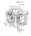
図1乃至図6は本発明の車両用ディスクブレーキの一形態例を示す図で、矢印Aは車両前進時に前輪と一体に回転するディスクロータの回転方向であり、以下で述べるディスク回出側及びディスク回入側とは車両前進時におけるものとする。 FIGS. 1 to 6 are views showing one embodiment of the disk brake for a vehicle according to the present invention. An arrow A indicates a rotation direction of a disk rotor that rotates integrally with a front wheel when the vehicle moves forward. The disk entry side is when the vehicle is moving forward.
この車両用ディスクブレーキ1は、前進時に車輪と一体に矢印A方向へ回転するディスクロータ2と、該ディスクロータ2の一側部で車体に固設されるキャリパブラケット3と、該キャリパブラケット3に一対のスライドピン4a,4bを介してディスク軸方向へスライド可能に支持されるピンスライド型のキャリパボディ5と、該キャリパボディ5の作用部5aと反作用部5bの間に、ディスクロータ2を挟んで対向配置される一対の摩擦パッド6,6とを備えている。
The
キャリパブラケット3は、ディスク回出側のディスク外周側に、ディスクロータ2の外側をディスク軸と平行に跨ぐキャリパ支持腕3aが延設され、該キャリパ支持腕3aに一方のスライドピン4aが装着され、また、キャリパブラケット3のディスク回入側で且つディスク内周側に、他方のスライドピン4bが装着される。さらに、キャリパブラケット3のディスク回出側で且つディスク内周側には、車体取付孔3b,3bが設けられている。また、キャリパ支持腕3aのディスク半径方向内側には、断面コ字状のトルク受け溝3cが形成されている。
The caliper bracket 3 has a
キャリパボディ5は、ディスクロータ2の両側部に対向配置される上述の作用部5aと反作用部5bと、ディスクロータ2の外側を跨いでこれらをつなぐブリッジ部5cとからなっている。作用部5aには、シリンダ孔5dと一対の車体取り付け腕5e,5eと、ユニオン孔5f及びブリーダスクリュ5gとが設けられ、シリンダ孔5dには、ピストン7がピストンシール8を介して内挿され、ピストン7とシリンダ孔5dの底壁との間には、液圧室9が画成されている。ピストン7は、有底円筒状のコップ形に形成され、先端開口面にピストン内周側に突出する爪部7aが全周に亘ってリング状に形成されている。
The
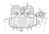
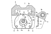
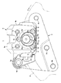
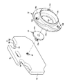
反作用部5bにはシリンダ孔切削用通孔5hの両側に一対の反力爪5i,5iが設けられている。さらに、反力爪5i,5iのディスクロータ側面5kのシリンダ孔切削用通孔5hの周囲にはダルマ状の凹部5mが形成され、該凹部5mに、ディスクロータ側面5kよりもディスクロータ側に突出し、反作用部側の摩擦パッド6の裏板6aに当接する補強プレート10が着脱可能に取り付けられている。また、反力爪5i,5iの反ディスクロータ側面には、シリンダ孔切削用通孔5h側の反力爪先端側とブリッジ部側の3箇所に、ボルト装着用凹部5nが形成され、各ボルト装着用凹部5nにボルト孔5pがそれぞれ穿設されている。
The
補強プレート10は、摩擦パッド6の裏板6aに当接する略半円状の当接部10aと、該当接部10aの反ディスクロータ側に形成され、前記凹部5mに嵌め込まれるダルマ状の嵌入部10bと、該嵌入部10bの反ディスクロータ側に形成され、シリンダ孔切削用通孔5hの内周に嵌合されるリング状の突出部10cとを備え、双方の反力爪先端側とブリッジ部側の3箇所に、嵌入部10bと当接部10aとに亘る雌ねじ孔10dが前記ボルト孔5pと同軸に形成され、さらに、当接部10aのシリンダ孔切削用通孔5hに対応した位置に、シリンダ孔切削用通孔5hよりも小径となる係止孔10eが穿設されている。また、係止孔10eの径は、前記ピストン7に形成された爪部7aの内径と同一に形成されている。
The reinforcing
各摩擦パッド6は、金属製の裏板6aの一側面に、ディスクロータ2の側面と摺接するライニング6bを接合して構成され、裏板6aの上部中央には吊下げ片6cが突設され、該吊下げ片6cの両側部にハンガーピン11,11を挿通するハンガーピン挿通溝6d,6dが形成されている。また、裏板6aのディスク回出側には、前記トルク受け溝3cに挿入される耳片6eが突設され、さらに、裏板6aの他側面のディスクロータ周方向中央部に、係止部材12を取り付けるための雌ねじ孔6fが形成されている。各摩擦パッド6は、前記ハンガーピン挿通溝6d,6dに、作用部5aと反作用部5bとに形成されたハンガーピン装着孔に架け渡されるハンガーピン11,11をそれぞれ挿通し、前記耳片6eをリテーナ13を介して前記トルク受け溝3cに挿入することにより、ディスク軸方向に移動可能に吊持される。
Each
各係止部材12は、裏板6aの前記雌ねじ孔6fに螺着される雄ねじ部12aを備えた軸部12bと、該軸部12bの反ディスクロータ側先端に形成され、作用部側ではピストン7の爪部7aに、反作用部側では補強プレート10の係止孔10eの内周部にそれぞれ係止するフランジ部12cを備えている。軸部12bの長さは、前記爪部7a及び前記当接部10aの厚さと等しいか、僅かに大きく設定されている。また、フランジ部12cは、爪部7aや係止孔10eの内側を通過可能なように、爪部7aや係止孔10eの内径より小径に形成されている。
Each locking
上述のように形成された摩擦パッド6,6のキャリパボディ5への組み付けは、まず、反力爪5i,5iのディスクロータ側面側から、補強プレート10の突出部10cをシリンダ孔切削用通孔5hの周壁に沿わせながら挿入し、前記凹部5mに嵌入部10bを嵌め込み、反力爪5iの反ディスクロータ側から各ボルト孔5pに取付ボルト14(本発明の締結部材)をそれぞれ挿入すると共に、前記雌ねじ孔10dに、取付ボルト14の雄ねじ部14aを螺合させることにより、反力爪5i,5iに補強プレート10を取り付ける。次に、作用部側では、摩擦パッド6の裏板6aに取り付けられた係止部材12のフランジ部12cを爪部7aのピストン底部側に配置させてフランジ部12cと爪部7aとを係止させ、反作用部側では、摩擦パッド6の裏板6aに取り付けられた係止部材12のフランジ部12cを係止孔10eの突出部10c側に配置させてフランジ部12cと係止孔10eの内周部とを係止させ、前記ハンガーピン挿通溝6d,6dに前記ハンガーピン11,11を挿通して摩擦パッド6,6をキャリパボディ5に吊持する。
Assembling of the
本形態例の車両用ディスクブレーキ1によれば、制動時に、図示しない周知の液圧マスタシリンダで発生した液圧が、ユニオン孔5fを介して液圧室9に供給されると、ピストン7がシリンダ孔5dをディスクロータ方向へ前進して、作用部側の摩擦パッド6をディスクロータ2の一側面へ押圧する。次に、この反力によって、キャリパボディ5がスライドピン4,4に案内されながら作用部5a方向へ移動し、反作用部側の反力爪5i,5iが補強プレート10を介して反作用部側の摩擦パッド6をディスクロータ2の他側面へ押圧する。この時、補強プレート10の当接部10aは、シリンダ孔切削用通孔5hの内径方向の一部を覆っていることから、摩擦パッド6の裏板6aのピストン7に対向する中央部分に当接して、反力爪5i,5iで受けるよりも広い面積でピストン7からの押圧力を受けることができ、反力爪5i,5iが摩耗することがない。また、補強プレート10が摩耗した際には、補強プレート10のみを交換すれば良く、コストの低減化を図ることができる。
According to the
さらに、反作用部5bのディスクロータ側面5kに補強プレート10を嵌め込む凹部5mを形成し、該凹部5mに嵌入部10bを嵌着し、取付ボルト14を螺着することにより、補強プレート10を反力爪5iに簡単に装着することができ、また、取付ボルト14を取り外すことにより、補強プレート10を簡単に取り外すことができる。さらに、凹部5mと嵌入部10bとをダルマ状に形成すると共に、補強プレート10に、シリンダ孔切削用通孔5hの内周に嵌合する突出部10cを設けたことにより、補強プレート10をキャリパボディ5に簡単、且つ、確実に装着させることができる。
Further, a
また、摩擦パッド6,6をキャリパボディ5に組み付けた状態では、作用部側の摩擦パッド6は、係止部材12がピストンに形成した爪部7aに係止してピストン7に保持され、反作用部側の摩擦パッド6は、係止部材12が補強プレート10の係止孔10eの内周部に係止して補強プレート10に保持されていることから、組み付けの際に、摩擦パッド6,6がディスクロータ2に対して傾くことがなく、ディスクロータ2の付いた車輪を車体に良好に組み付けることができる。また、制動解除時には、ピストン7や反力爪5iと共に摩擦パッド6,6をディスクロータ2から引き離すことができることから、摩擦パッド6,6の引き摺りを抑制することができる。また、爪部の内径と係止孔とを同径に形成したことにより、作用部側の摩擦パッドと反作用部側の摩擦パッドに同一の係止部材を用いることができる。
Further, in a state where the
尚、本発明は上述の形態例に限るものではなく、多ポットのピンスライド型ディスクブレーキにも適用することができ、補強プレートは、適宜、反力爪のディスクロータ側面に取り付ければ良い。また、補強プレートは、突出部を備えていなくても良い。また、係止部材や係止孔やピストンの爪部を備えていない物でも良く、さらに、反作用部に設ける凹部や補強プレートに設ける嵌入部を省略することもでき、当接部を直接反力爪のディスクロータ側面に取り付けるようにしても良い。 The present invention is not limited to the above-described embodiment, but can be applied to a multi-pot pin slide type disc brake. The reinforcing plate may be appropriately attached to the side surface of the disc rotor of the reaction force claw. Further, the reinforcing plate may not include the protruding portion. Moreover, the thing which does not have a latching member, a latching hole, or the nail | claw part of a piston may be sufficient, Furthermore, the recessed part provided in a reaction part and the insertion part provided in a reinforcement plate can also be abbreviate | omitted, and a contact part is made direct reaction force. You may make it attach to the disk rotor side surface of a nail | claw.
1…車両用ディスクブレーキ、2…ディスクロータ、3…キャリパブラケット、3a…車体取付孔、3b…ピン取付孔、3c…トルク受け溝、4a,4b…スライドピン、5…キャリパボディ、5a…作用部、5b…反作用部、5c…ブリッジ部、5d…シリンダ孔、5e…車体取り付け腕、5f…ユニオン孔、5g…ブリーダスクリュ、5h…シリンダ孔切削用通孔、5i…反力爪、5k…ディスクロータ側面、5m…凹部、5n…ボルト装着用凹部、5p…ボルト孔、6…摩擦パッド、6a…裏板、6b…ライニング、6c…吊下げ片、6d…ハンガーピン挿通溝、6e…耳片、6f…雌ねじ孔、7…ピストン、7a…爪部、8…ピストンシール、9…液圧室、10…補強プレート、10a…当接部、10b…嵌入部、10c…突出部、10d…雌ねじ孔、10e…係止孔、11…ハンガーピン、12…係止部材、12a…雄ねじ部、12b…軸部、12c…フランジ部、13…リテーナ、14…取付ボルト、14a…雄ねじ部
DESCRIPTION OF
Claims (6)
Priority Applications (1)
| Application Number | Priority Date | Filing Date | Title |
|---|---|---|---|
| JP2011028135A JP5603797B2 (en) | 2011-02-14 | 2011-02-14 | Vehicle disc brake |
Applications Claiming Priority (1)
| Application Number | Priority Date | Filing Date | Title |
|---|---|---|---|
| JP2011028135A JP5603797B2 (en) | 2011-02-14 | 2011-02-14 | Vehicle disc brake |
Publications (2)
| Publication Number | Publication Date |
|---|---|
| JP2012167724A true JP2012167724A (en) | 2012-09-06 |
| JP5603797B2 JP5603797B2 (en) | 2014-10-08 |
Family
ID=46972074
Family Applications (1)
| Application Number | Title | Priority Date | Filing Date |
|---|---|---|---|
| JP2011028135A Expired - Fee Related JP5603797B2 (en) | 2011-02-14 | 2011-02-14 | Vehicle disc brake |
Country Status (1)
| Country | Link |
|---|---|
| JP (1) | JP5603797B2 (en) |
Cited By (1)
| Publication number | Priority date | Publication date | Assignee | Title |
|---|---|---|---|---|
| DE102022212780A1 (en) * | 2022-11-29 | 2024-05-29 | Hl Mando Corporation | Disc brake system |
Citations (6)
| Publication number | Priority date | Publication date | Assignee | Title |
|---|---|---|---|---|
| JPS59113328A (en) * | 1982-12-07 | 1984-06-30 | アルフレツド・テヴエス・ゲ−エムベ−ハ− | Brake caliper housing and its manufacturing method |
| JPS60110734U (en) * | 1983-12-29 | 1985-07-27 | 日信工業株式会社 | Insulator with wear alarm for vehicle disc brake device |
| JPS62151441U (en) * | 1986-03-18 | 1987-09-25 | ||
| JPH02138238U (en) * | 1989-04-21 | 1990-11-19 | ||
| JPH0654930U (en) * | 1993-01-11 | 1994-07-26 | 日信工業株式会社 | Caliper body for vehicle disc brakes |
| JP2010121721A (en) * | 2008-11-20 | 2010-06-03 | Akebono Brake Ind Co Ltd | Floating caliper type disc brake |
-
2011
- 2011-02-14 JP JP2011028135A patent/JP5603797B2/en not_active Expired - Fee Related
Patent Citations (6)
| Publication number | Priority date | Publication date | Assignee | Title |
|---|---|---|---|---|
| JPS59113328A (en) * | 1982-12-07 | 1984-06-30 | アルフレツド・テヴエス・ゲ−エムベ−ハ− | Brake caliper housing and its manufacturing method |
| JPS60110734U (en) * | 1983-12-29 | 1985-07-27 | 日信工業株式会社 | Insulator with wear alarm for vehicle disc brake device |
| JPS62151441U (en) * | 1986-03-18 | 1987-09-25 | ||
| JPH02138238U (en) * | 1989-04-21 | 1990-11-19 | ||
| JPH0654930U (en) * | 1993-01-11 | 1994-07-26 | 日信工業株式会社 | Caliper body for vehicle disc brakes |
| JP2010121721A (en) * | 2008-11-20 | 2010-06-03 | Akebono Brake Ind Co Ltd | Floating caliper type disc brake |
Cited By (1)
| Publication number | Priority date | Publication date | Assignee | Title |
|---|---|---|---|---|
| DE102022212780A1 (en) * | 2022-11-29 | 2024-05-29 | Hl Mando Corporation | Disc brake system |
Also Published As
| Publication number | Publication date |
|---|---|
| JP5603797B2 (en) | 2014-10-08 |
Similar Documents
| Publication | Publication Date | Title |
|---|---|---|
| JP5847561B2 (en) | Disc brake | |
| JP7572418B2 (en) | Vehicle disc brakes | |
| EP3680504B1 (en) | Vehicular disc brake | |
| JP5726151B2 (en) | Vehicle disc brake | |
| WO2016080451A1 (en) | Disc brake device | |
| WO2014175388A1 (en) | Disc brake device | |
| JP5919316B2 (en) | Vehicle disc brake | |
| JP5332014B2 (en) | Decorative plate mounting structure | |
| JP5879032B2 (en) | Disc brake | |
| JP5603797B2 (en) | Vehicle disc brake | |
| JP2016028215A (en) | Disc brake | |
| JP2009133356A (en) | Floating caliper type disc brake | |
| JP2016017558A (en) | Disc brake device | |
| JP6182435B2 (en) | Vehicle disc brake | |
| JP4880250B2 (en) | Vehicle disc brake | |
| WO2010137715A1 (en) | Disc brake for vehicles | |
| JP5544263B2 (en) | Brake pads | |
| JP2015007439A (en) | Disc brake for vehicle | |
| JP2020159369A (en) | Vehicle disc brakes | |
| JP4387852B2 (en) | Vehicle disc brake | |
| JP5436387B2 (en) | Vehicle disc brake | |
| JP2012072843A (en) | Floating type disc brake | |
| JP2013190035A (en) | Vehicle disk brake | |
| JP5607015B2 (en) | Vehicle disc brake | |
| JP4590427B2 (en) | Pin slide type vehicle disc brake |
Legal Events
| Date | Code | Title | Description |
|---|---|---|---|
| A621 | Written request for application examination |
Free format text: JAPANESE INTERMEDIATE CODE: A621 Effective date: 20130415 |
|
| A977 | Report on retrieval |
Free format text: JAPANESE INTERMEDIATE CODE: A971007 Effective date: 20131212 |
|
| A131 | Notification of reasons for refusal |
Free format text: JAPANESE INTERMEDIATE CODE: A131 Effective date: 20140107 |
|
| A521 | Request for written amendment filed |
Free format text: JAPANESE INTERMEDIATE CODE: A523 Effective date: 20140307 |
|
| TRDD | Decision of grant or rejection written | ||
| A01 | Written decision to grant a patent or to grant a registration (utility model) |
Free format text: JAPANESE INTERMEDIATE CODE: A01 Effective date: 20140812 |
|
| A61 | First payment of annual fees (during grant procedure) |
Free format text: JAPANESE INTERMEDIATE CODE: A61 Effective date: 20140822 |
|
| R150 | Certificate of patent or registration of utility model |
Ref document number: 5603797 Country of ref document: JP Free format text: JAPANESE INTERMEDIATE CODE: R150 |
|
| R250 | Receipt of annual fees |
Free format text: JAPANESE INTERMEDIATE CODE: R250 |
|
| R250 | Receipt of annual fees |
Free format text: JAPANESE INTERMEDIATE CODE: R250 |
|
| R250 | Receipt of annual fees |
Free format text: JAPANESE INTERMEDIATE CODE: R250 |
|
| R250 | Receipt of annual fees |
Free format text: JAPANESE INTERMEDIATE CODE: R250 |
|
| LAPS | Cancellation because of no payment of annual fees |