JP2012168432A - Developing device and image forming apparatus - Google Patents
Developing device and image forming apparatus Download PDFInfo
- Publication number
- JP2012168432A JP2012168432A JP2011030600A JP2011030600A JP2012168432A JP 2012168432 A JP2012168432 A JP 2012168432A JP 2011030600 A JP2011030600 A JP 2011030600A JP 2011030600 A JP2011030600 A JP 2011030600A JP 2012168432 A JP2012168432 A JP 2012168432A
- Authority
- JP
- Japan
- Prior art keywords
- toner
- magnetic
- developer
- rotator
- roller
- Prior art date
- Legal status (The legal status is an assumption and is not a legal conclusion. Google has not performed a legal analysis and makes no representation as to the accuracy of the status listed.)
- Withdrawn
Links
Images


Landscapes
- Dry Development In Electrophotography (AREA)
Abstract
【課題】飛散トナー捕捉カバーに捕捉して堆積された飛散トナーがトナー担持回転体の表面に付着して現像されることを抑制できる現像装置を提供する。
【解決手段】磁気ブラシ194が形成される現像剤担持回転体130と、現像剤担持回転体130から供給されるトナー192を担持して磁気ブラシ194によりトナー層193を形成するトナー担持回転体150と、トナー担持回転体150と像担持体2aとの間に現像バイアス電圧を印加する電圧印加部と、先端部142を現像剤担持回転体130に近接させることにより、現像剤担持回転体130に担持される現像剤190の量を規制する規制部材140と、飛散トナー捕捉カバー141と、を備え、トナー担持回転体150の回転方向Cが、現像剤担持回転体130の回転方向Bに対して順方向の回転方向に設定されている。
【選択図】図3The present invention provides a developing device capable of suppressing the scattered toner trapped and deposited on a scattered toner capturing cover from adhering to the surface of a toner-carrying rotating body and developing.
A developer carrying rotator 130 on which a magnetic brush 194 is formed, and a toner carrying rotator 150 carrying a toner 192 supplied from the developer carrying rotator 130 and forming a toner layer 193 by the magnetic brush 194. And a voltage applying unit for applying a developing bias voltage between the toner carrying rotator 150 and the image carrying member 2a, and a tip 142 close to the developer carrying rotator 130, thereby allowing the developer carrying rotator 130 to A regulating member 140 that regulates the amount of developer 190 carried and a scattered toner capturing cover 141 are provided, and the rotation direction C of the toner carrying rotary body 150 is relative to the rotation direction B of the developer carrying rotary body 130. The forward rotation direction is set.
[Selection] Figure 3
Description
本発明は、電子写真方式により形成された静電潜像を現像するための現像装置、及び該現像装置を備える画像形成装置に関する。 The present invention relates to a developing device for developing an electrostatic latent image formed by an electrophotographic method, and an image forming apparatus including the developing device.
近年、少なくともキャリア及びトナーを含む2成分現像剤を、現像剤担持回転体の表面に担持させて磁気ブラシを形成し、磁気ブラシからトナー担持回転体に供給されるトナーにより、トナー担持回転体の表面にトナー層を形成し、トナー層から像担持体にトナーを飛翔させることにより、像担持体の表面の静電潜像をトナー画像として現像する、いわゆる、タッチダウン方式(ハイブリッド方式とも言われる。)の現像装置が注目されている。 In recent years, a two-component developer containing at least a carrier and a toner is supported on the surface of a developer-carrying rotator to form a magnetic brush, and toner supplied from the magnetic brush to the toner-carrying rotator A so-called touch-down method (also called a hybrid method) is developed in which an electrostatic latent image on the surface of the image carrier is developed as a toner image by forming a toner layer on the surface and causing the toner to fly from the toner layer to the image carrier. )) Is attracting attention.
タッチダウン方式の現像装置においては、一般的に、先端部を現像剤担持回転体の表面に近接させて、現像剤担持回転体に担持される現像剤の量を規制する規制部材と、規制部材の上方に配置されて、現像剤担持回転体から外方へ飛散されるトナーを捕捉して堆積させる飛散トナー捕捉カバーと、を備えている。そのため、長時間に亘って連続的に現像が行われた場合、飛散トナー捕捉カバーに捕捉されて堆積されるトナーの量が次第に増加し、堆積されたトナー量が一定以上に増えると、帯電性の低いトナーが現像剤担持回転体の表面の磁気ブラシと接触して、磁気ブラシにより汲み上げられる。そして、磁気ブラシに汲み上げられた帯電性の低いトナーの一部は、トナー担持回転体へ移行(供給)された後、像担持体の表面の静電潜像に飛翔されて現像されることになる。そのため、現像時において、帯電性の低いトナーが現像領域に落下する、いわゆる、トナー落ちによって画像不良が発生しやすい。 In a touch-down type developing device, generally, a regulating member that regulates the amount of developer carried on the developer-carrying rotator by bringing the tip portion close to the surface of the developer-carrying rotator, and a regulating member And a scattered toner capturing cover for capturing and depositing toner scattered outward from the developer carrying rotator. Therefore, when the development is continuously performed for a long time, the amount of toner trapped and deposited on the scattering toner trap cover gradually increases, and when the deposited toner amount increases beyond a certain level, The low-toner toner comes into contact with the magnetic brush on the surface of the developer-carrying rotating body and is pumped up by the magnetic brush. Then, a part of the low-chargeable toner pumped up by the magnetic brush is transferred (supplied) to the toner-carrying rotator, and then jumped to the electrostatic latent image on the surface of the image-carrying member and developed. Become. For this reason, at the time of development, a toner with low chargeability falls to the development region, and so-called toner drop tends to cause image defects.
従来、現像剤担持回転体からのトナーの飛散対策として、現像剤担持回転体とトナー担持回転体との間に、内部に磁性部材(磁石)が配設されたトナー回収ローラを配置し、トナー回収ローラにより現像剤担持回転体及びトナー担持回転体の近傍に浮遊する飛散トナーを捕集し、その捕集した飛散トナーを現像装置の内部に戻すようにした現像装置が提案されている(例えば、特許文献1参照)。 Conventionally, as a countermeasure against scattering of toner from a developer carrying rotator, a toner collecting roller having a magnetic member (magnet) disposed therein is disposed between the developer carrying rotator and the toner carrying rotator. There has been proposed a developing device that collects scattered toner floating in the vicinity of the developer carrying rotator and the toner carrying rotator by a collecting roller and returns the collected scattered toner to the inside of the developing device (for example, , See Patent Document 1).
しかし、特許文献1に記載される現像装置においても、トナー回収ローラにより飛散トナーの全てを捕集して現像装置の内部に戻すことはできず、そのため、現像時間が長くなると、飛散トナー捕捉カバーに飛散トナーが堆積し、堆積したトナーが現像剤担持回転体により汲み上げられる。そして、特許文献1に記載される現像装置においては、現像剤担持回転体の表面とトナー担持回転体の表面とが、両担持回転体の対向位置において互いに反対方向に回転移動するカウンタ回転式に構成されている。そのため、現像剤担持回転体により汲み上げられたトナーは、両担持回転体のギャップ間を通過せずに、両担持回転体のギャップ間に形成される磁界の影響を受けて、トナー担持回転体の表面に付着する。その結果、前述したようなトナー落ちによる画像不良の発生が生じてしまう。 However, even in the developing device described in Patent Document 1, it is not possible to collect all of the scattered toner by the toner recovery roller and return it to the inside of the developing device. The scattered toner accumulates on the surface, and the accumulated toner is pumped up by the developer carrying rotor. In the developing device described in Patent Document 1, the surface of the developer-carrying rotator and the surface of the toner-carrying rotator are rotated in a counter-rotation manner in which the surfaces of both the carrying rotators are rotated in opposite directions. It is configured. For this reason, the toner pumped up by the developer-carrying rotator does not pass between the gaps of both the supported rotators, but is affected by the magnetic field formed between the gaps of the two supported rotators, Adhere to the surface. As a result, the above-described image failure occurs due to toner dropping.
本発明は、飛散トナー捕捉カバーに捕捉して堆積された飛散トナーがトナー担持回転体の表面に付着して現像されることに起因するトナー落ち等の画像不良の発生を抑制することができる現像装置を提供することを目的とする。
また、本発明は、前記現像装置を備える画像形成装置を提供することを目的とする。
The present invention is a development that can suppress the occurrence of image defects such as toner dropping due to the scattered toner trapped and deposited on the scattered toner trapping cover adhering to the surface of the toner carrying rotor. An object is to provide an apparatus.
Another object of the present invention is to provide an image forming apparatus including the developing device.
本発明は、少なくともキャリア及びトナーを含む2成分現像剤を担持し、該2成分現像剤に含まれるキャリアによる磁気ブラシが表面に形成される現像剤担持回転体と、前記現像剤担持回転体の上方に対向配置され、前記現像剤担持回転体から供給されるトナーを担持して前記磁気ブラシによりトナー層を形成するトナー担持回転体と、前記トナー担持回転体に担持されたトナーを像担持体の表面の静電潜像に飛翔させて静電潜像をトナー画像として現像するために、前記トナー担持回転体と前記像担持体との間に現像バイアス電圧を印加する電圧印加部と、前記現像剤担持回転体の回転中心を通る水平面よりも下方に位置し、先端部を前記現像剤担持回転体の表面に近接させることにより、該現像剤担持回転体に担持される現像剤の量を規制する規制部材と、前記規制部材の上方に配置されて、前記現像剤担持回転体から外方へ飛散するトナーを捕捉して堆積させる飛散トナー捕捉カバーと、を備え、前記トナー担持回転体の回転方向が、前記現像剤担持回転体の回転方向に対して順方向の回転方向に設定されている現像装置に関する。 The present invention provides a developer-carrying rotator that carries a two-component developer containing at least a carrier and a toner, a magnetic brush formed of a carrier contained in the two-component developer is formed on the surface, and the developer-carrying rotator. A toner-carrying rotator that is arranged to face the upper side and carries toner supplied from the developer-carrying rotator and forms a toner layer by the magnetic brush; and the toner carried by the toner-carrying rotator and the image carrier A voltage applying unit for applying a developing bias voltage between the toner carrying rotator and the image carrying member in order to fly the electrostatic latent image on the surface of the toner and developing the electrostatic latent image as a toner image; The amount of the developer carried on the developer-carrying rotator is reduced by positioning the tip part close to the surface of the developer-carrying rotator, which is located below the horizontal plane passing through the rotation center of the developer-carrying rotator. Rule And a scattering toner capturing cover that is disposed above the restricting member and captures and deposits toner scattered outward from the developer-carrying rotator, and rotates the toner-carrying rotator. The present invention relates to a developing device in which a direction is set to a forward rotation direction with respect to a rotation direction of the developer carrying rotator.
また、前記トナー担持回転体と前記現像剤担持回転体とが最も接近する最接近位置よりも両担持回転体の上流側の位置に、第2の磁気ブラシ回転体を、更に備えることが好ましい。 In addition, it is preferable that a second magnetic brush rotator is further provided at a position upstream of the two carrying rotators from the closest position where the toner carrying rotator and the developer carrying rotator are closest to each other.
また、前記第2の磁気ブラシ回転体の回転方向は、前記トナー担持回転体の回転方向に対して順方向の回転方向に設定されていることが好ましい。 The rotation direction of the second magnetic brush rotator is preferably set to a forward rotation direction with respect to the rotation direction of the toner carrying rotator.
また、前記第2の磁気ブラシ回転体の直径は、前記現像剤担持回転体の直径の2分の1以下に設定されていることが好ましい。 In addition, it is preferable that the diameter of the second magnetic brush rotator is set to be equal to or less than half of the diameter of the developer carrying rotator.
また、前記第2の磁気ブラシ回転体は、その回転速度を、前記現像剤担持回転体の回転速度に対して2倍以上の速度に変更可能に、構成されていることが好ましい。 Further, it is preferable that the second magnetic brush rotator is configured to be capable of changing its rotation speed to a speed twice or more that of the developer carrying rotator.
また、本発明は、前記現像装置と、表面に静電潜像が形成されると共に、前記現像装置の前記トナー層からトナーの供給を受けて静電潜像にトナー画像が形成される1又は複数の像担持体と、前記像担持体に形成されたトナー画像を直接的又は間接的にシート状の被転写材に転写する転写部と、転写されたトナー画像をシート状の被転写材に定着する定着部と、を備える画像形成装置に関する。 According to the present invention, an electrostatic latent image is formed on the surface of the developing device, and a toner image is formed on the electrostatic latent image by receiving toner from the toner layer of the developing device. A plurality of image carriers, a transfer unit that directly or indirectly transfers a toner image formed on the image carrier to a sheet-like transfer material, and the transferred toner image on a sheet-like transfer material The present invention relates to an image forming apparatus including a fixing unit for fixing.
本発明によれば、飛散トナー捕捉カバーに捕捉して堆積された飛散トナーがトナー担持回転体の表面に付着して現像されることに起因するトナー落ち等の画像不良の発生を抑制することができる現像装置を提供することができる。
また、本発明によれば、前記現像装置を備える画像形成装置を提供することができる。
According to the present invention, it is possible to suppress the occurrence of image defects such as toner dropping due to the scattered toner trapped and accumulated on the scattered toner capturing cover adhering to the surface of the toner carrying rotor. A developing device capable of being provided can be provided.
In addition, according to the present invention, an image forming apparatus including the developing device can be provided.
以下、図面を参照して本発明の実施形態を説明する。
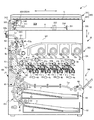
図1により、本実施形態における画像形成装置としてのコピー機1における全体構造を説明する。図1は、コピー機1の各構成要素の配置を説明するための図である。
Hereinafter, embodiments of the present invention will be described with reference to the drawings.
With reference to FIG. 1, the overall structure of a copier 1 as an image forming apparatus in the present embodiment will be described. FIG. 1 is a diagram for explaining the arrangement of each component of the copier 1.
図1に示すように、画像形成装置としてのコピー機1は、コピー機1における上下方向Zの上方側に配置される画像読取装置300と、コピー機1における上下方向Zの下方側に配置され画像読取装置300により読み取られた画像情報に基づいてシート状の被画像形成材としての用紙Tにトナー画像を形成する装置本体Mと、を備える。
なお、コピー機1の説明において、副走査方向Xをコピー機1の「左右方向」ともいい、主走査方向Y(図1を貫く方向)をコピー機1の「前後方向」ともいう。コピー機1の上下方向Zは、副走査方向X及び主走査方向Yと直交する。
As shown in FIG. 1, a copier 1 as an image forming apparatus is disposed on an upper side in the vertical direction Z of the copier 1 and on a lower side of the copier 1 in the vertical direction Z. An apparatus main body M that forms a toner image on a sheet T as a sheet-like image forming material based on image information read by the
In the description of the copying machine 1, the sub-scanning direction X is also referred to as “left-right direction” of the copying machine 1, and the main scanning direction Y (direction passing through FIG. 1) is also referred to as “front-back direction” of the copying machine 1. The vertical direction Z of the copier 1 is orthogonal to the sub-scanning direction X and the main scanning direction Y.
まず、画像読取装置300について説明する。
図1に示すように、画像読取装置300は、蓋部材70と、原稿Gの画像を読み取る読取部301と、を備える。
蓋部材70は、読取部301に対して不図示の連結部により開閉可能に連結されている。蓋部材70は、後述する読取面302Aを保護する機能を有する。
First, the
As shown in FIG. 1, the
The lid member 70 is connected to the
読取部301は、筐体306と、筐体306の上方側に配置される読取面302Aと、を備える。また、読取部301は、筐体306の内部空間304に、光源を含む照明部340と、複数のミラー321、322及び323と、副走査方向Xに移動する第1枠体311及び第2枠体312と、結像レンズ357と、読取装置としてのCCD358と、CCD358により読み取られた画像情報に対して所定の処理をすると共に該画像情報を装置本体M側に出力させるCCD基板361と、を備える。照明部340及び第1ミラー321は、第1枠体311に収容される。第2ミラー322及び第3ミラー323は、第2枠体312に収容される。
The
読取面302Aは、副走査方向X及び主走査方向Yと直交する方向に拡がり、読取部301における副走査方向Xの大部分に亘っている。原稿Gは、読取面302Aに載置される。第1枠体311及び第2枠体312それぞれは、後述する光路Hの長さ(光路長)を一定に保持しながら副走査方向Xに移動する。これにより、読取面302Aに載置された原稿Gの画像が読み取られる。
The
筐体306の内部空間304において、複数のミラー321、322及び323は、原稿Gからの光を結像レンズ357に入光させるための光路Hを形成する。また、第1枠体311が副走査方向Xに一定速度Aで移動すると共に、第2枠体312が副走査方向Xに一定速度A/2で移動するため、画像読み取り動作時においても、光路Hの長さは一定に維持される。これにより、読取面302Aに載置された原稿Gの画像が読取面302Aに読み取られる。
In the
次に、装置本体Mについて説明する。
装置本体Mは、所定の画像情報に基づいて用紙Tに所定のトナー画像を形成する画像形成部GKと、用紙Tを画像形成部GKに給紙すると共にトナー画像が形成された用紙Tを排紙する給排紙部KHとを有する。
装置本体Mにおける外形は、筐体部としてのケース体BDにより構成される。
Next, the apparatus main body M will be described.
The main body M of the apparatus forms an image forming unit GK that forms a predetermined toner image on the paper T based on predetermined image information, and feeds the paper T to the image forming unit GK and discharges the paper T on which the toner image is formed. A paper supply / discharge unit KH for paper.
The outer shape of the apparatus main body M is configured by a case body BD as a casing.
図1に示すように、画像形成部GKは、像担持体(感光体)としての感光体ドラム2a、2b、2c、2dと、帯電部10a、10b、10c、10dと、露光ユニットとしてのレーザスキャナユニット4a、4b、4c、4dと、現像装置16a、16b、16c、16dと、トナーカートリッジ5a、5b、5c、5dと、トナー供給部6a、6b、6c、6dと、ドラムクリーニング部11a、11b、11c、11dと、除電器12a、12b、12c、12dと、中間転写ベルト7と、1次転写ローラ37a、37b、37c、37dと、2次転写ローラ8と、対向ローラ18と、定着部9と、を備える。
As shown in FIG. 1, the image forming unit GK includes
図1に示すように、給排紙部KHは、給紙カセット52と、手差し給紙部64と、用紙Tの搬送路Lと、レジストローラ対80と、第1排紙部50aと、第2排紙部50bとを備える。なお、搬送路Lは、後述するように、第1搬送路L1と、第2搬送路L2と、第3搬送路L3と、手差し搬送路Laと、戻り搬送路Lbと、後処理搬送路Lcとの集合体である。
As shown in FIG. 1, the paper feed / discharge unit KH includes a
以下、画像形成部GK及び給排紙部KHの各構成について詳細に説明する。
まず、画像形成部GKについて説明する。
画像形成部GKにおいては、感光体ドラム2a、2b、2c、2dそれぞれの表面に沿って上流側から下流側に順に、帯電部10a、10b、10c、10dによる帯電、レーザスキャナユニット4a、4b、4c、4dによる露光、現像装置16a、16b、16c、16dによる現像、中間転写ベルト7及び1次転写ローラ37a、37b、37c、37dによる1次転写、除電器12a、12b、12c、12dによる除電、及びドラムクリーニング部11a、11b、11c、11dによるクリーニングが行われる。
また、画像形成部GKにおいては、中間転写ベルト7、2次転写ローラ8及び対向ローラ18による2次転写、並びに定着部9による定着が行われる。
Hereinafter, each configuration of the image forming unit GK and the paper supply / discharge unit KH will be described in detail.
First, the image forming unit GK will be described.
In the image forming unit GK, charging by the charging
Further, in the image forming unit GK, secondary transfer by the intermediate transfer belt 7, the secondary transfer roller 8 and the
感光体ドラム2a、2b、2c、2dそれぞれは、円筒形状の部材からなり、感光体又は像担持体として機能する。感光体ドラム2a、2b、2c、2dそれぞれは、中間転写ベルト7の進行方向に対して直交する方向に延びる機軸を中心に矢印の方向に回転可能に配置される。感光体ドラム2a、2b、2c、2dそれぞれにおける表面には、静電潜像が形成され得る。
Each of the
帯電部10a、10b、10c、10dそれぞれは、感光体ドラム2a、2b、2c、2dそれぞれの表面に対向して配置される。帯電部10a、10b、10c、10dそれぞれは、感光体ドラム2a、2b、2c、2dそれぞれの表面を一様に負(マイナス極性)又は正(プラス極性)に帯電させる。
Each of the charging
レーザスキャナユニット4a、4b、4c、4dは、露光ユニットとして機能するものであり、感光体ドラム2a、2b、2c、2dそれぞれの表面から離間して配置される。レーザスキャナユニット4a、4b、4c、4dそれぞれは、不図示のレーザ光源、ポリゴンミラー、ポリゴンミラー駆動用モータ等を有して構成される。
The
レーザスキャナユニット4a、4b、4c、4dそれぞれは、読取部301により読み込まれた画像に関する画像情報に基づいて感光体ドラム2a、2b、2c、2dそれぞれの表面を走査露光する。レーザスキャナユニット4a、4b、4c、4dそれぞれにより走査露光されることで、感光体ドラム2a、2b、2c、2dそれぞれの表面の露光された部分の電荷が除去される。これにより、感光体ドラム2a、2b、2c、2dそれぞれの表面に静電潜像が形成される。
Each of the
現像装置16a、16b、16c、16dそれぞれは、感光体ドラム2a、2b、2c、2dにそれぞれ対応して設けられ、感光体ドラム2a、2b、2c、2dの表面に対向して配置される。現像装置16a、16b、16c、16dそれぞれは、感光体ドラム2a、2b、2c、2dそれぞれの表面に形成された静電潜像に各色のトナーを付着させて、カラーのトナー画像を感光体ドラム2a、2b、2c、2dそれぞれの表面に形成する。現像装置16a、16b、16c、16dそれぞれは、イエロー、シアン、マゼンタ、ブラックの4つの色に対応する。現像装置16a、16b、16c、16dそれぞれの詳細については後述する。
The developing
トナーカートリッジ5a、5b、5c、5dそれぞれは、現像装置16a、16b、16c、16dそれぞれに対応して設けられており、現像装置16a、16b、16c、16dそれぞれに対して供給される各色のトナーを収容する。トナーカートリッジ5a、5b、5c、5dそれぞれは、イエローのトナー、シアンのトナー、マゼンタのトナー、ブラックのトナーを収容する。
The
トナー供給部6a、6b、6c、6dそれぞれは、トナーカートリッジ5a、5b、5c、5d及び現像装置16a、16b、16c、16dにそれぞれ対応して設けられており、トナーカートリッジ5a、5b、5c、5dそれぞれに収容された各色のトナーを、現像装置16a、16b、16c、16dそれぞれに対して供給する。トナー供給部6a、6b、6c、6dそれぞれと現像装置16a、16b、16c、16dそれぞれとは、不図示のトナー供給路により結ばれている。
The
中間転写ベルト7には、感光体ドラム2a、2b、2c、2dに形成された各色のトナー画像が順次1次転写される。中間転写ベルト7は、従動ローラ35、駆動ローラからなる対向ローラ18、テンションローラ36等に掛け渡される。テンションローラ36が中間転写ベルト7を内側から外側に付勢するため、中間転写ベルト7には所定の張力が与えられる。
To the intermediate transfer belt 7, the toner images of the respective colors formed on the
中間転写ベルト7を挟んで感光体ドラム2a、2b、2c、2dと反対の側には、1次転写ローラ37a、37b、37c、37dそれぞれが対向して配置される。
中間転写ベルト7における所定部分は、1次転写ローラ37a、37b、37c、37dそれぞれと、感光体ドラム2a、2b、2c、2dそれぞれとにより挟み込まれる。この挟み込まれた所定部分は、感光体ドラム2a、2b、2c、2dそれぞれにおける表面に押し当てられる。感光体ドラム2a、2b、2c、2dそれぞれと1次転写ローラ37a、37b、37c、37dそれぞれとの間で、それぞれ1次転写ニップN1a、N1b、N1c、N1dが形成される。1次転写ニップN1a、N1b、N1c、N1dそれぞれにおいて、感光体ドラム2a、2b、2c、2dそれぞれに現像された各色のトナー画像が中間転写ベルト7に順次1次転写される。これにより、中間転写ベルト7には、フルカラーのトナー画像が形成される。
A predetermined portion of the intermediate transfer belt 7 is sandwiched between the
1次転写ローラ37a、37b、37c、37dそれぞれには、不図示の1次転写バイアス印加部により、感光体ドラム2a、2b、2c、2dそれぞれに形成された各色のトナー画像を中間転写ベルト7に転写させるための1次転写バイアスが印加される。
To the
除電器12a、12b、12c、12dそれぞれは、感光体ドラム2a、2b、2c、2dそれぞれの表面に対向して配置される。除電器12a、12b、12c、12dそれぞれは、感光体ドラム2a、2b、2c、2dそれぞれの表面に光を照射することにより、1次転写が行われた後の感光体ドラム2a、2b、2c、2dそれぞれの表面を除電する(電荷を除去する)。
The
ドラムクリーニング部11a、11b、11c、11dそれぞれは、感光体ドラム2a、2b、2c、2dそれぞれの表面に対向して配置される。ドラムクリーニング部11a、11b、11c、11dそれぞれは、感光体ドラム2a、2b、2c、2dそれぞれの表面に残存したトナーや付着物を除去すると共に、除去されたトナー等を所定の回収機構へ搬送して、回収させる。
The
2次転写ローラ8は、中間転写ベルト7に1次転写されたフルカラーのトナー画像を用紙Tに2次転写させる。2次転写ローラ8には、不図示の2次転写バイアス印加部により、中間転写ベルト7に形成されたフルカラーのトナー画像を用紙Tに転写させるための2次転写バイアスが印加される。 The secondary transfer roller 8 secondarily transfers the full-color toner image primarily transferred to the intermediate transfer belt 7 onto the paper T. A secondary transfer bias for transferring the full color toner image formed on the intermediate transfer belt 7 to the paper T is applied to the secondary transfer roller 8 by a secondary transfer bias applying unit (not shown).
2次転写ローラ8は、中間転写ベルト7に対して当接したり離間したりする。具体的には、2次転写ローラ8は、中間転写ベルト7に当接される当接位置と中間転写ベルト7から離間する離間位置とに移動可能に構成される。詳細には、2次転写ローラ8は、中間転写ベルト7の表面に1次転写されたフルカラ−のトナー画像を用紙Tに2次転写させる場合には当接位置に配置され、他の場合には離間位置に配置される。 The secondary transfer roller 8 contacts or separates from the intermediate transfer belt 7. Specifically, the secondary transfer roller 8 is configured to be movable between a contact position where the secondary transfer roller 8 is in contact with the intermediate transfer belt 7 and a spaced position where the secondary transfer roller 8 is separated from the intermediate transfer belt 7. Specifically, the secondary transfer roller 8 is disposed at the contact position when the full-color toner image primarily transferred onto the surface of the intermediate transfer belt 7 is secondarily transferred to the paper T, and in other cases. Are arranged at spaced positions.
中間転写ベルト7における2次転写ローラ8とは反対側には、対向ローラ18が配置される。中間転写ベルト7における所定部分は、2次転写ローラ8と対向ローラ18とによって挟み込まれる。そして、用紙Tは中間転写ベルト7の外面(トナー画像が1次転写された面)に押し当てられる。中間転写ベルト7と2次転写ローラ8との間で2次転写ニップN2が形成される。2次転写ニップN2において、中間転写ベルト7に1次転写されたフルカラーのトナー画像が用紙Tに2次転写される。
A
定着部9は、用紙Tに2次転写されたトナー画像を構成する各色のトナーを溶融及び加熱して、用紙Tに定着させる。定着部9は、ヒータにより加熱される加熱回転体9aと、加熱回転体9aに圧接される加圧回転体9bと、を備える。加熱回転体9aと加圧回転体9bとは、トナー画像が2次転写された用紙Tを挟み込んで加圧すると共に、搬送する。加熱回転体9aと加圧回転体9bとの間に挟まれた状態で用紙Tが搬送されることによって、用紙Tに転写されたトナーは、溶融及び加圧されることで、用紙Tに定着される。
The fixing unit 9 melts and heats the toner of each color constituting the toner image secondarily transferred onto the paper T and fixes the toner on the paper T. The fixing unit 9 includes a
次に、給排紙部KHについて説明する。
図1に示すように、装置本体Mの下部には、用紙Tを収容する2個の給紙カセット52が上下に配列されて配置される。給紙カセット52は、装置本体Mの筐体から水平方向に引き出し可能に構成される。給紙カセット52には、用紙Tが載置される載置板60が配置される。給紙カセット52には、用紙Tが載置板60の上に積層された状態で収容される。載置板60に載置された用紙Tは、給紙カセット52における用紙送り出し側の端部(図1において左側の端部)に配置されるカセット給紙部51により搬送路Lに送り出される。カセット給紙部51は、載置板60上の用紙Tを取り出すための前送りコロ61と、用紙Tを1枚ずつ搬送路Lに送り出すための給紙ローラ対63とからなる重送防止機構を備える。
Next, the paper supply / discharge unit KH will be described.
As shown in FIG. 1, in the lower part of the apparatus main body M, two
装置本体Mの右側面(図1において右側)には、手差し給紙部64が設けられる。手差し給紙部64は、給紙カセット52にセットされる用紙Tとは異なる大きさや種類の用紙Tを装置本体Mに供給することを主目的として設けられる。手差し給紙部64は、閉状態において装置本体Mの右側面の一部を構成する手差しトレイ65と、給送ローラとしての給紙コロ66とを備える。手差しトレイ65は、開状態において1又は複数の用紙Tを載置可能な載置部として機能し、その下端が給紙コロ66の近傍に回動自在(開閉自在)に取り付けられる。給紙コロ66は、開状態の手差しトレイ65に載置された用紙Tを筐体306の内部の手差し搬送路Laに向けて送り出す(給紙する)。
A manual
装置本体Mにおける上方側には、第1排紙部50a及び第2排紙部50bが設けられる。第1排紙部50a及び第2排紙部50bは、用紙Tを装置本体Mの外部に排紙する。第1排紙部50a及び第2排紙部50bの詳細については後述する。
A first
用紙Tを搬送する搬送路Lは、カセット給紙部51から2次転写ニップN2までの第1搬送路L1と、2次転写ニップN2から定着部9までの第2搬送路L2と、定着部9から第1排紙部50aまでの第3搬送路L3と、手差し給紙部64から供給される用紙を第1搬送路L1に合流させる手差し搬送路Laと、第3搬送路L3を上流側から下流側へ搬送する用紙を表裏反転させて第1搬送路L1に戻す戻り搬送路Lbと、第3搬送路L3を上流側から下流側へ搬送する用紙を第2排紙部50bに接続された後処理装置(図示せず)に搬送する後処理搬送路Lcと、を備える。
The conveyance path L for conveying the paper T includes a first conveyance path L1 from the cassette paper feeding unit 51 to the secondary transfer nip N2, a second conveyance path L2 from the secondary transfer nip N2 to the fixing unit 9, and a fixing unit. 9 to the first
また、第1搬送路L1の途中には、第1合流部P1及び第2合流部P2が設けられている。第3搬送路L3の途中には、第1分岐部Q1が設けられている。
第1合流部P1は、手差し搬送路Laが第1搬送路L1に合流する合流部である。第2合流部P2は、戻り搬送路Lbが第1搬送路L1に合流する合流部である。
第1分岐部Q1は、後処理搬送路Lcが第3搬送路L3から分岐する分岐部である。第1分岐部Q1には、整流部材58が設けられている。整流部材58は、定着部9から搬出された用紙Tの搬送方向を、第1排紙部50aに向かう第3搬送路L3又は第2排紙部50bに向かう後処理搬送路Lcに整流させる(切り換える)。
Moreover, the 1st junction part P1 and the 2nd junction part P2 are provided in the middle of the 1st conveyance path L1. A first branch portion Q1 is provided in the middle of the third transport path L3.
The first joining part P1 is a joining part where the manual feed path La joins the first transport path L1. The second junction P2 is a junction where the return conveyance path Lb merges with the first conveyance path L1.
The first branch portion Q1 is a branch portion where the post-processing transport path Lc branches from the third transport path L3. A rectifying
第1搬送路L1の途中(詳細には、第2合流部P2と2次転写ローラ8との間)には、用紙Tを検出するためのセンサと、用紙Tのスキュー(斜め給紙)補正や画像形成部GKにおけるトナー画像の形成とタイミングを合わせるためのレジストローラ対80とが配置される。センサは、用紙Tの搬送方向におけるレジストローラ対80の直前(搬送方向における上流側)に配置される。レジストローラ対80は、センサからの検出信号情報に基づいて上述の補正やタイミング調整をして用紙Tを搬送する。
In the middle of the first transport path L1 (specifically, between the second joining portion P2 and the secondary transfer roller 8), a sensor for detecting the paper T and correction of the skew (oblique paper feeding) of the paper T In addition, a
戻し搬送路Lbは、用紙Tに両面印刷を行う際に、既に印刷されている面とは反対面(未印刷面)を中間転写ベルト7に対向させるために設けられる搬送路である。戻し搬送路Lbによれば、第1分岐部Q1から第1排紙部50a側に搬送された用紙Tを表裏反転させて第1搬送路L1に戻して、2次転写ローラ8の上流側に配置されたレジストローラ対80の上流側に搬送させることができる。戻し搬送路Lbにより表裏反転された用紙Tには、2次転写ニップN2において未印刷面に対して所定のトナー画像が転写される。
The return conveyance path Lb is a conveyance path that is provided to make the opposite surface (unprinted surface) opposite to the already printed surface to the intermediate transfer belt 7 when performing duplex printing on the paper T. According to the return conveyance path Lb, the sheet T conveyed from the first branching section Q1 to the first
第3搬送路L3における端部には、第1排紙部50aが形成される。第1排紙部50aは、装置本体Mにおける上方側に配置される。第1排紙部50aは、装置本体Mの右側面側(図1において右側、手差し給紙部64側)に向けて開口している。第1排紙部50aは、第3搬送路L3を搬送される用紙Tを装置本体Mの外部に排紙する。
A first
第1排紙部50aにおける開口側には、排紙集積部M1が形成される。排紙集積部M1は、装置本体Mにおける上面(外面)に形成される。排紙集積部M1は、装置本体Mにおける上面が下方に窪んで形成された部分である。排紙集積部M1の底面は、装置本体Mにおける上面の一部を構成する。排紙集積部M1には、所定のトナー画像が形成され第1排紙部50aから排紙された用紙Tが積層して集積される。
On the opening side of the first
後処理搬送路Lcにおける端部には、第2排紙部50bが形成される。第2排紙部50bは、装置本体Mにおける上方側に配置される。第2排紙部50bは、装置本体Mの左側面側(図1において左側、後処理装置が連結される側)に向けて開口している。第2排紙部50bは、後処理搬送路Lcを搬送される用紙Tを装置本体Mの外部に排紙する。
第2排紙部50bにおける開口側には、後処理装置(図示せず)が連結される。後処理装置は、画像形成装置(コピー機1)から排出される用紙の後処理(ステープル、パンチ等)を行うものである。
なお、各搬送路の所定位置には用紙検出用のセンサが配置される。
A second
A post-processing device (not shown) is connected to the opening side of the second
A paper detection sensor is disposed at a predetermined position on each conveyance path.
次に、主搬送路L1からL3(第1搬送路L1、第2搬送路L2及び第3搬送路L3を合わせて以下「主搬送路」ともいう)及び戻り搬送路Lbにおける紙詰まり(JAM)を解消するための構造について簡単に説明する。
図1に示すように、装置本体Mの左側面側(図1において左側)には、主搬送路L1からL3及び戻り搬送路Lbが主に上下方向に延びるように並列している。装置本体Mの左側面側(図1において左側)には、装置本体Mの側面の一部を形成するように、カバー体40が設けられている。カバー体40は、その下端部において、支点軸43を介して装置本体Mに連結されている。支点軸43は、その軸方向が主搬送路L1からL3及び戻り搬送路Lbを横断する方向に沿って配設されている。カバー体40は、支点軸43を中心として閉位置(図1に示す位置)と開位置(図示せず)との間を回動自在に構成されている。
Next, a paper jam (JAM) in the main transport path L1 to L3 (the first transport path L1, the second transport path L2, and the third transport path L3 are collectively referred to as “main transport path” hereinafter) and the return transport path Lb. A structure for eliminating the problem will be briefly described.
As shown in FIG. 1, on the left side surface of the apparatus main body M (left side in FIG. 1), main conveyance paths L1 to L3 and a return conveyance path Lb are arranged in parallel so as to mainly extend in the vertical direction. A
カバー体40は、支点軸43によって装置本体Mに回動自在に連結された第1のカバー部41と、同じ支点軸43によって装置本体Mに回動自在に連結された第2のカバー部42とから構成されている。第1のカバー部41は、第2のカバー部42よりも装置本体Mの外側(側面側)に位置する。なお、図1において、左下がりの破線でハッチングされた部分が第1のカバー部41であり、右下がりの破線でハッチングされた部分が第2のカバー部42である。
The
カバー体40が閉位置に位置する状態において、第1のカバー部41は、その外面側が装置本体Mの外面(側面)の一部を形成している。
また、カバー体40が閉位置に位置する状態において、第2のカバー部42は、その内面側(装置本体M側)が主搬送路L1からL3の一部を形成している。
更に、カバー体40が閉位置に位置する状態において、第1のカバー部41の内面側と第2のカバー部42の外面側とが、戻り搬送路Lbの少なくとも一部を形成している。つまり、戻り搬送路Lbは、第1のカバー部41と第2のカバー部42との間に形成されている。
In the state where the
In the state where the
Further, in a state where the
本実施形態のコピー機1は、このような構成のカバー体40を備えることにより、主搬送路L1からL3で紙詰まり(JAM)が発生した際には、カバー体40を図1に示す閉位置から、開位置(図示せず)に回動して主搬送路L1からL3を開放することにより、主搬送路L1からL3に詰まった用紙を処理することができる。一方、戻り搬送路Lbで紙詰まりが発生した際には、カバー体40を開位置に回動した後、支点軸43を中心に第2のカバー部42を装置本体M側(図1において右側)に回動させて戻り搬送路Lbを開放することにより、戻り搬送路Lbに詰まった用紙を処理することができる。
The copying machine 1 of the present embodiment includes the
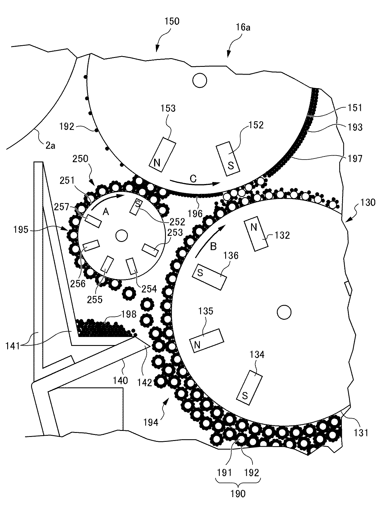
次に、図2から図4を参照して、本実施形態のコピー機1の特徴部分である現像装置16a,16b,16c,16dに係る構成について説明する。前述の通り、コピー機1は、4個の現像装置16a,16b,16c,16dを備えているが、それぞれ同様の構成を有しているため、ここでは現像装置16aを代表して用いて説明する。
図2は、本実施形態のコピー機における現像装置16aの構成要素及び感光体ドラム2aを説明するための断面図である。図3は、図2の部分拡大図である。図4は、現像ローラ150の表面に所定厚さのトナー層193が形成される様子を示す部分拡大図である。
Next, with reference to FIGS. 2 to 4, a configuration related to the developing
FIG. 2 is a cross-sectional view for explaining the components of the developing
図2及び図3に示すように、本実施形態の現像装置16aは、少なくとも磁性キャリア及びトナーを含む2成分現像剤を収容する現像容器110と、現像容器110の内部に配置される攪拌ローラ120a、120bと、一方の攪拌ローラ120aの垂直方向における上方に配置される現像剤担持体としての磁気ローラ130と、磁気ローラ130に近接して配置される層厚規制ブレード(規制部材)140と、層厚規制ブレード140の垂直方向における上方に配置される飛散トナー捕捉カバー141と、磁気ローラ130に対向して配置されるトナー担持体としての現像ローラ150と、第2の磁気ブラシ回転体250と、第2の磁気ブラシ回転体250を回転駆動する回転駆動部260と、回転駆動部260による第2の磁気ブラシ回転体250の回転速度を変更する回転制御部261と、を備える。
As shown in FIGS. 2 and 3, the developing
現像容器110には、トナーカートリッジ5a(図1参照)からトナー供給部6a(図1参照)を介してトナー192が供給される。
攪拌ローラ120a、120bは、現像容器110に収容された2成分現像剤190を攪拌する。攪拌された2成分現像剤190には、摩擦により静電気が発生し、磁性キャリア(キャリア)191はマイナスに帯電し、トナー192はプラスに帯電する。また、静電気力により、トナー192は、磁性キャリア191に付着する。
To the developing
The stirring
磁気ローラ130は、回転中心130Cを中心に所定方向に回転可能で且つ磁気ローラ130の表面を構成する磁気スリーブ131と、磁気スリーブ131の内部に配置された複数の磁気ローラ磁極部材132から136と、を備える。
磁気スリーブ131は、円筒形状を有し、非磁性部材により構成される。磁気スリーブ131は、図2及び図3に示す矢印Bの方向に回転駆動される。磁気スリーブ131には、電圧印加部(図示せず)により、第1バイアス電圧が印加される。
The
The
図2及び図3に示すように、複数の磁気ローラ磁極部材132から136は、磁気スリーブ131の内部において、磁気ローラ130の回転方向に並んで所定間隔あけて固定される。
第1磁気ローラ磁極部材132は、磁気ローラ130における現像ローラ150に最も近接する位置に固定されて配置される。第1磁気ローラ磁極部材132は、外側(磁気スリーブ131の周面側)にN極が位置するように配置される。
As shown in FIGS. 2 and 3, the plurality of magnetic roller
The first magnetic roller
その他の磁気ローラ磁極部材133から136は、磁気スリーブ131の内部において、第1磁気ローラ磁極部材132よりも回転方向Bの上流側に所定間隔をあけて固定される。磁気ローラ磁極部材133,134,136は、外側(磁気スリーブ131の周面側)にS極が位置するように配置される。磁気ローラ磁極部材135は、外側(磁気スリーブ131の周面側)にN極が位置するように配置される。
The other magnetic roller
図3及び図4に示すように、磁気ローラ磁極部材132から136の磁力によって、現像容器110に収容された2成分現像剤190の一部は、磁気スリーブ131の表面に保持される。また、磁気ローラ130の表面に保持された2成分現像剤190は、現像剤層(磁気ブラシ)194を形成する。
As shown in FIGS. 3 and 4, a part of the two-
層厚規制ブレード140は、磁気ローラ130の回転中心130Cを通る水平面130Hよりも下方に位置する。層厚規制ブレード140は、その先端部142を磁気ローラ130の表面に対向し且つ近接させることにより、磁気ローラ130の表面に保持された2成分現像剤190により形成された現像剤層194の層厚(高さ)を規制して、この層厚規制ブレード140を通過した現像剤層194の層厚を一定に保つ。層厚規制ブレード140は、板状の部材からなる。層厚規制ブレード140の先端部142と磁気スリーブ131の表面との間には、所定の隙間(ギャップ)が形成される。
The layer
飛散トナー捕捉カバー141は、現像装置16aのケース体の一部を構成する部材である。飛散トナー捕捉カバー141は、層厚規制ブレード140の垂直方向における上方の側方(図2における左側)に配置されて、トナー192が現像装置16aの外部へ飛散することを抑制する。
The scattered
現像ローラ150は、磁気ローラ130に対向して配置される。現像ローラ150の表面には、磁気ローラ130から移動したトナー192により、トナー層193が形成される。具体的には、層厚規制ブレード140により層厚が規制された現像剤層(磁気ブラシ)194から現像ローラ150の表面にトナー192が移動されて、トナー層193が形成される。現像ローラ150は、現像ローラ150の表面を構成する現像スリーブ151と、現像スリーブ151の内部に配置された第1現像ローラ磁極部材152及び第2現像ローラ磁極部材153と、を備える。
The developing
現像スリーブ151は、円筒形状を有し、非磁性部材により構成される。現像スリーブ151は、磁気スリーブ131と対向する位置において、磁気スリーブ131の移動方向と同一の方向(図2及び図3に示す矢印Cの方向)となるように、回転駆動される。即ち、現像ローラ150の回転方向Cは、磁気ローラ130の回転方向Bに対して順方向(トレイル方向)に設定されている。
現像ローラ150の現像スリーブ151には、電圧印加部262により第2バイアス電圧が印加される。
The developing
A second bias voltage is applied to the developing
第1現像ローラ磁極部材152は、現像スリーブ151の内部において、第1磁気ローラ磁極部材132と対向して固定配置される。第1現像ローラ磁極部材152は、磁気ローラ130と現像ローラ150とが最も近接する領域を挟んで、互いに所定の間隔をあけて配置される。言い換えると、第1現像ローラ磁極部材152と第1磁気ローラ磁極部材132とは、現像スリーブ151と磁気スリーブ131とが最も近接する領域を挟んで、互いに対向して配置される。
The first developing roller
第1現像ローラ磁極部材152は、第1磁気ローラ磁極部材132と向かい合う側の端部において、第1磁気ローラ磁極部材132における外側の極性とは異なる極性を有する。つまり、第1現像ローラ磁極部材152は、外側(現像スリーブ151の周面側)にS極が位置するように配置される。また、第2現像ローラ磁極部材153は、外側(現像スリーブ151の周面側)にN極が位置するように配置される。
The first developing roller
そして、磁気ローラ130の内部に配置された第1磁気ローラ磁極部材132と、現像ローラ150の内部に配置された第1現像ローラ磁極部材152との間には、第1の磁界171が形成される。磁気ローラ130と現像ローラ150との間における磁界171が形成された領域においては、現像剤層194は、第1の磁界171の影響を受けて磁気ローラ130の表面から立ち上がり、磁気ブラシを形成して現像ローラ150に接触する。
ここで、第1の磁界171の磁気拘束力は、後述するように、磁気ローラ130が飛散トナー捕捉カバー141上に堆積した飛散トナーを汲み上げて移送するときに、その汲み上げて移送される飛散トナーを含む磁気ブラシが磁気ローラ130と現像ローラ150との間のギャップを容易に通過することができる程度の大きさに設定されている。
A first
Here, as will be described later, when the
第2の磁気ブラシ回転体250は、現像ローラ150の表面と磁気ローラ130の表面とが最も接近する最接近位置161よりも両ローラ150、130の回転方向B、Cの上流側の位置に配置される。第2の磁気ブラシ回転体250は、磁気ローラ130の表面に形成された現像剤層(磁気ブラシ)194の一部を受け取り、表面に第2の磁気ブラシ195を形成して、現像ローラ150に接触する。
The second
第2の磁気ブラシ回転体250は、回転駆動部260と、回転駆動部260による第2の磁気ブラシ回転体250の回転速度を変更する回転制御部261と、を備えている。回転制御部261は、用紙Tに印刷を行なう通常印字時には、第2の磁気ブラシ回転体250の線速度が磁気ローラ130の線速度と同一になるように、回転駆動部260を制御する。また、回転制御部261は、用紙Tに印刷を行わない非印字時には、第2の磁気ブラシ回転体250の線速度が例えば磁気ローラ130の線速度の1.5倍以上、好ましくは2倍以上になるように、第2の磁気ブラシ回転体250の回転速度を2段階に変更(切り替え)するように、回転駆動部260を制御する。
The second
第2の磁気ブラシ回転体250は、所定方向に回転可能で且つ第2の磁気ブラシ回転体250の表面を構成する第2の磁気スリーブ251と、磁気スリーブ25の内部に配置された複数の回転体磁極部材252から257と、を備える。
第2の磁気ブラシ回転体250の直径D2は、例えば、磁気ローラ130の直径D1の2分の1以下に、好ましくは、磁気ローラ130の直径D1の3分の1以下に、設定されている。
The second
The diameter D2 of the second magnetic
第2の磁気スリーブ251は、円筒形状であり、非磁性部材により構成される。第2の磁気スリーブ251は、図2及び図3に示す矢印Aの方向、つまり、現像ローラ150の回転方向Cに対して順方向に回転駆動(トレイル回転駆動)される。第2の磁気スリーブ251には、電圧印加部(図示せず)により、第3バイアス電圧が印加される。
The second
図2及び図3に示すように、複数の回転体磁極部材252から257は、第2の磁気スリーブ251の内部において、第2の磁気ブラシ回転体250の回転方向に並んで所定間隔あけて固定される。
複数の回転体磁極部材252から257のうち第1回転体磁極部材252は、第2の磁気ブラシ回転体250における現像ローラ150に最も近接する位置に固定されて配置される。第1磁気ローラ磁極部材252は、外側(第2の磁気スリーブ251の周面側)にS極が位置するように配置される。
As shown in FIGS. 2 and 3, the plurality of rotating body
Of the plurality of rotating body
その他の回転体磁極部材253から257は、第2の磁気スリーブ251の内部において、第1回転体磁極部材252よりも回転方向Aの上流側に所定間隔をあけて固定される。
The other rotating body
図4に示すように、複数の回転体磁極部材252から257の磁力によって、現像容器110に収容された2成分現像剤190の一部は、磁気スリーブ131の表面から第2の磁気ブラシ回転体250に引き取られて、第2の磁気スリーブ251の表面に保持される。また、第2の磁気スリーブ251の表面に保持された2成分現像剤190は、現像剤層(磁気ブラシ)195を形成する。
As shown in FIG. 4, a part of the two-
第2の磁気ブラシ回転体250における第1回転体磁極部材252は、第2の磁気スリーブ251の内部において、現像スリーブ151と第2の磁気スリーブ251とが最も近接する領域を挟んで、現像ローラ150側の第2現像ローラ磁極部材153に対向して配置される。
The first
第1回転体磁極部材252においては、現像ローラ150側の第2現像ローラ磁極部材153と向かい合う側の端部は、第2現像ローラ磁極部材153における外側の極性とは異なる極性を有する。つまり、第1回転体磁極部材252は、外側(第2の磁気スリーブ251の周面側)にS極が位置するように配置される。これにより、第2の磁気ブラシ回転体250の内部に配置された第1回転体磁極部材252と、現像ローラ150の内部に配置された第2現像ローラ磁極部材153との間には、第2の磁界172が形成される。第2の磁気ブラシ回転体250と現像ローラ150との間における第2の磁界172が形成された領域において、現像剤層195は、第2の磁界172の影響を受けて、第2の磁気ブラシ回転体250の表面から立ち上がり、磁気ブラシを形成して現像ローラ150に接触する。
In the first rotator
次に、本実施形態の現像装置16aの動作について、図2から図4を参照しながら説明する。
本実施形態の現像装置16aにおいては、トナーカートリッジ5a(図1参照)から供給された2成分現像剤190が、まず、攪拌ローラ120a,120bにより攪拌され、現像容器110の内部を循環する。これにより、攪拌された2成分現像剤190には、摩擦による静電気が発生し、磁性キャリア191はマイナスに帯電し、トナー192はプラスに帯電する。また、静電気力により磁性キャリア191にトナー192が付着する。
Next, the operation of the developing
In the developing
現像容器110の内部において帯電した2成分現像剤190は、磁気スリーブ131の内部に配置された磁気ローラ磁極部材132から136の磁力により、回転方向Bに回転する磁気ローラ130の表面に保持される。また、複数の磁気ローラ磁極部材134,135の磁力により、磁気ローラ130の表面には、現像剤層(磁気キャリア)194が形成される。
磁気ローラ130の表面に形成された現像剤層194は、磁気スリーブ131の回転に伴って回転移動され、層厚規制ブレード140に接触して所定の層厚に規制される。
The two-
The
層厚規制ブレード140により所定の層厚に規制された現像剤層194は、磁気ローラ130の回転に伴って、第2の磁気ブラシ回転体250との対向位置の近傍まで回転移動される。この領域において、現像剤層194の一部は、第2の磁気ブラシ回転体250の内部に配置された回転体磁極部材252から257の磁力により、回転方向Aに回転する第2の磁気ブラシ回転体250の表面に保持され、現像剤層(磁気ブラシ)195を形成する。
The
また、磁気ローラ130の表面に形成され所定の層厚に規制された現像剤層194の残部は、磁気ローラ130の第1磁気ローラ磁極部材132と現像ローラ150の第1現像ローラ磁極部材152との対向位置の近傍に回転移動されて、第1の磁界171が形成された領域に達する。この領域において、現像剤層194は、第1の磁界171の影響を受けて立ち上がって、現像ローラ150に接触する。
Further, the remainder of the
また、第2の磁気ブラシ回転体250の表面に保持された現像剤層195は、第2の磁気ブラシ回転体250と現像ローラ150との対向位置の近傍に移動され、第2の磁界172が形成された領域を通過する。この領域において、現像剤層195は、磁気拘束力の強い第2の磁界172の影響を受けて立ち上がり、現像ローラ150に接触する。
Further, the
第2の磁気ブラシ回転体250の表面に保持された現像剤層195においてプラスに帯電しているトナー192は、第2の磁気ブラシ回転体250に印加された第3バイアス電圧と現像ローラ150に印加された第2バイアス電圧との電位差に応じて現像ローラ150側に移送され、現像ローラ150の表面に第1トナー層196を形成する。
The
一方、磁気ローラ130の表面に保持された現像剤層194は、磁気ローラ130と現像ローラ150との対向位置の近傍に移動され、第1の磁界171が形成された領域を通過する。この領域において、現像剤層194は、磁気拘束力の強い第1の磁界171の影響を受けて立ち上がり、現像ローラ150の表面に接触し、現像剤層194中のプラスに帯電しているトナー192は、磁気ローラ130に印加された第1バイアス電圧と現像ローラ150に印加された第2バイアス電圧との電位差に応じて現像ローラ150側に移送される。これにより、現像ローラ150の表面に形成された第1トナー層196の表面に、第2トナー層197が重層して形成される。これら第1トナー層196と第2トナー層197とにより、現像ローラ150の表面には、所定厚さのトナー層193が形成される。
On the other hand, the
その後、所定厚さのトナー層193が形成された現像ローラ150の表面は、回転方向Cの下流側において、感光体ドラム2a(図1参照)の表面と対向する。そして、現像領域において、現像ローラ150と感光体ドラム2aとの電位差によって静電潜像が現像される。つまり、感光体ドラム2aにおいては、表面に静電潜像が形成されると共に、現像装置16aのトナー層193からトナーの供給を受けて、静電潜像にトナー画像が形成される。
Thereafter, the surface of the developing
そして、図1に示すように、感光体ドラム2aに現像されたトナー画像が中間転写ベルト7に順次1次転写される。中間転写ベルト7に1次転写されたトナー画像は、2次転写ローラ8により用紙Tに2次転写される。用紙Tに2次転写されたトナー画像は定着部9に搬送されて、定着部9によりトナーが用紙Tに定着される。
その後、用紙Tは、第3搬送路L3により第1排紙部50aに搬送され、第1排紙部50aから排紙集積部M1に排出される。このようにして、コピー機1による用紙Tの印刷が完了する。
As shown in FIG. 1, the toner images developed on the
Thereafter, the paper T is transported to the first
上述のような現像装置16aによる現像動作時において、磁気ローラ130から外方へ飛散する飛散トナー198は、飛散トナー捕捉カバー141により捕捉されて次第に堆積される。飛散トナー捕捉カバー141に捕捉され堆積された飛散トナー198の堆積量が一定以上に達すると、その堆積した飛散トナー198は、磁気ローラ130により汲み上げられる。そして、磁気ローラ130により汲み上げられた飛散トナー198は、磁気ローラ130の回転に伴い、磁気ローラ130と現像ローラ150との対向位置の近傍に移動される。
During the developing operation by the developing
ここで、磁気ローラ130と現像ローラ150とが順方向回転(トレイル回転)しているため、磁気ローラ130により汲み上げられて磁気ローラ130と現像ローラ150との対向位置の近傍に移動された飛散トナー198は、磁気ローラ130と現像ローラ150との間のギャップを通過する。飛散トナー198が磁気ローラ130と現像ローラ150との間のギャップを通過することにより、第1の磁界171の影響を受けて、飛散トナー198はほぐされることになる。
Here, since the
このようにほぐされた飛散トナー198の大部分は、現像容器110の内部に脱落して回収され、この脱落した回収トナーを含む現像剤190が、攪拌ローラ120a,120bにより攪拌され、帯電されることになる。
一方、磁気ローラ130と現像ローラ150との間のギャップを通過した飛散トナー198の一部は、現像ローラ150の表面に付着するが、磁気ローラ130と現像ローラ150との間のギャップを通過する際に、第1の磁界171の影響を受けてほぐされているため、現像ローラ150の表面のトナー層193に付着されていくことによるトナー落ちによる画像不良の発生を抑制することができる。
Most of the loosened
On the other hand, part of the
また、第2の磁気ブラシ回転体250は、回転制御部261により、用紙Tに印刷を行なう通常印字時には、第2の磁気ブラシ回転体250の線速度が磁気ローラ130の線速度と同一に回転制御されるが、用紙Tに印刷を行わない非印字時には、第2の磁気ブラシ回転体250の線速度が磁気ローラ130の線速度の2倍以上になるように回転(切り替え)制御される。これにより、非印字時において、第2の磁気ブラシ回転体250から現像ローラ150への現像剤190の供給性能(現像ゴースト性能)は十分に維持される。
In addition, the second
本実施形態のコピー機1における現像装置16aによれば、例えば、次のような効果が奏される。
本実施形態は、先端部142を磁気ローラ130の表面に近接させることにより、磁気ローラ130に担持される現像剤190の量を規制する層厚規制ブレード140、磁気ローラ130から外方へ飛散するトナーを捕捉して堆積させる飛散トナー捕捉カバー141と、を備え、現像ローラ150の回転方向Cが、磁気ローラ130の回転方向Bに対して順方向の回転方向に設定されている。
According to the developing
In the present embodiment, the
そのため、磁気ローラ130から外方に飛散されるトナーを捕捉する飛散トナー捕捉カバー141上に堆積された飛散トナー198が、磁気ローラ130により汲み上げられたときに、その汲み上げられた飛散トナー198を磁気ローラ130と現像ローラ150との間のギャップを通過させてほぐすことができる。これにより、磁気ローラ130により汲み上げられた飛散トナー198が現像ローラ150の表面のトナー層193に付着されることに起因するトナー落ちによる画像不良の発生を抑制することができる。
Therefore, when the
また、本実施形態においては、現像ローラ150と磁気ローラ130とが最も接近する最接近位置161よりも両ローラ150、130の上流側の位置に、第2の磁気ブラシ回転体250を備えている。
そのため、現像ローラ150と磁気ローラ130とがトレイル回転することに伴って低下する磁気ローラ130から現像ローラ150へのトナー層193の供給性能(現像ゴースト性能)を、第2の磁気ブラシ回転体250により補うことができる。これによって、現像ローラ150へのトナー層193のゴースト性能を十分に維持しつつ、トナー落ちによる画像不良の発生を抑制することができる。
In the present embodiment, the second magnetic
Therefore, the supply performance (development ghost performance) of the
また、本実施形態においては、第2の磁気ブラシ回転体250の直径D2が磁気ローラ130の直径D1の2分の1以下に設定されている。
そのため、現像装置16aの内部に特別な設置スペースを設けなくても、第2の磁気ブラシ回転体250を設置することが容易であり、例えば、飛散トナー捕捉カバー141の上方の空間部を利用して第2の磁気ブラシ回転体250を設置することができる。これにより、現像装置16aの全体を小型でコンパクトに構成しながら、上述のようなゴースト性能を確保することができる。
In the present embodiment, the diameter D2 of the second
Therefore, it is easy to install the second
更に、本実施形態においては、第2の磁気ブラシ回転体250の回転速度を、磁気ローラ130の回転速度に対して2倍以上の速度に変更可能に構成されている。
そのため、非印字時において、第2の磁気ブラシ回転体250の回転速度を磁気ローラ130の回転速度に対して2倍以上の速度に変更することにより、長時間に亘って連続印字を行なう場合に、現像ローラ150に飛散トナーが付着して発生する画像不良の問題を抑制することができる。
Further, in the present embodiment, the rotation speed of the second
Therefore, when continuous printing is performed over a long period of time by changing the rotation speed of the second
以上、本発明の好適な実施形態について説明したが、本発明は、上述した実施形態に限定されることなく、種々の形態で実施することができる。
例えば、前述の実施形態においては、トナー192がプラスに帯電した場合について説明しているが、これに制限されない。トナー192は、マイナスに帯電していてもよい。具体的には、前述の実施形態においては、プラスに帯電したトナー192を使用する場合について説明している。このように、プラスに帯電したトナー192を使用する場合には、第1バイアス電圧と第2バイアス電圧との差を大きくしている。
As mentioned above, although preferred embodiment of this invention was described, this invention can be implemented with a various form, without being limited to embodiment mentioned above.
For example, in the above-described embodiment, the case where the
これに対し、マイナスに帯電したトナー192を使用する場合には、第1バイアス電圧と第2バイアス電圧との差を小さくする。これにより、マイナスに帯電したトナー192を使用する場合においても、前述の実施形態と同様の効果を奏することができる。
この点以外におけるマイナスに帯電したトナー192を使用する場合における構成、作用及び効果は、プラスに帯電したトナー192を使用する場合と同様である。
On the other hand, when the negatively charged
Except for this point, the configuration, operation, and effect when the negatively charged
前述の実施形態は、中間転写ベルト7を用いて複数色のトナー画像を用紙Tに転写するカラーの間接転写方式の画像形成装置であるが、画像形成装置の種類は、これに制限されず、中間転写ベルトを用いない直接転写方式の画像形成装置や、モノクロ印刷用の画像形成装置であってもよい。 The above-described embodiment is a color indirect transfer type image forming apparatus that transfers a plurality of color toner images onto the paper T using the intermediate transfer belt 7, but the type of the image forming apparatus is not limited to this, The image forming apparatus may be a direct transfer type that does not use an intermediate transfer belt, or an image forming apparatus for monochrome printing.
本発明の画像形成装置の種類は、特に限定がなく、カラーコピー機、プリンタ、ファクシミリ、又はこれらの複合機などであってもよい。
シート状の被転写材としては、用紙Tに制限されず、例えば、フィルムシートであってもよい。
The type of the image forming apparatus of the present invention is not particularly limited, and may be a color copier, a printer, a facsimile, or a complex machine thereof.
The sheet-shaped transfer material is not limited to the paper T, and may be a film sheet, for example.
次に、本発明の実施例1から3及び比較例を用いて行った実験例について説明する。ただし、本発明は、以下の実験例のみに限定されるものでない。
実施例1:磁気ローラ130と現像ローラ150とがトレイル回転する(順方向に回転する)。
実施例2:磁気ローラ130と現像ローラ150とがトレイル回転し、第2の磁気ブラシ回転体250を備える。
実施例3:磁気ローラ130と現像ローラ150とがトレイル回転し、第2の磁気ブラシ回転体250を備え、非印字時に第2の磁気ブラシ回転体250の線速度を磁気ローラ130の線速度の2倍以上に変更する回転制御を行なう。
比較例:磁気ローラ130と現像ローラ150とがカウンタ回転する(逆方向に回転する)。
Next, experimental examples performed using Examples 1 to 3 of the present invention and a comparative example will be described. However, the present invention is not limited only to the following experimental examples.
Example 1: The
Example 2: The
Embodiment 3 The
Comparative example: The
実験に供した実施例1から3及び比較例の画像形成装置の仕様は、次の通りである。
感光体ドラム2a
直径:30mm、周速度:200mm/sec、表面電位:250V
現像ローラ150
直径:20mm、周速度:300mm/sec、印加電圧:Vdc=100V、Vpp1.8kV、周波数f=4.5kHz、Duty比=70%
磁気ローラ130
直径:20mm、周速度:450mm/sec、印加電圧:Vdc=可変、Vpp=1.8kV、周波数f=4.5kHz、Duty比=70%
第2の磁気ブラシ回転体250
直径:20mm、周速度:450mm/sec、印加電圧:Vdc=可変、Vpp=1.8kV、周波数f=4.5kHz、Duty比=70%
各ローラ間の距離
磁気ローラ130と現像ローラ150と間の距離=320mm
第2の磁気ブラシ回転体250と現像ローラ150と間の距離=320mm
現像ローラ150と感光体ドラム2aと間の距離=100mm
The specifications of the image forming apparatuses of Examples 1 to 3 and the comparative example used in the experiment are as follows.
Diameter: 30 mm, peripheral speed: 200 mm / sec, surface potential: 250 V
Diameter: 20 mm, peripheral speed: 300 mm / sec, applied voltage: Vdc = 100 V, Vpp 1.8 kV, frequency f = 4.5 kHz, duty ratio = 70%
Diameter: 20 mm, peripheral speed: 450 mm / sec, applied voltage: Vdc = variable, Vpp = 1.8 kV, frequency f = 4.5 kHz, duty ratio = 70%
Second
Diameter: 20 mm, peripheral speed: 450 mm / sec, applied voltage: Vdc = variable, Vpp = 1.8 kV, frequency f = 4.5 kHz, duty ratio = 70%
Distance between rollers Distance between
Distance between second
Distance between developing
また、2成分現像剤190としては、トナーの平均粒径:6μm、キャリアの平均粒径:35μm、トナーの帯電量:15μC/gのものを使用した。
As the two-
以上の各仕様で作製した画像形成装置を用いて、印字枚数が1000枚(10K)から3000枚(30K)の耐久試験を行ない、そのときのトナー落ちの発生件数をカウントすると共に、現像ローラ150の表面のトナー層193の供給性能(現像ゴースト性能)レベル及び現像ローラ150への飛散トナーの付着レベルの推移を測定し、それぞれの項目について評価した。
Using the image forming apparatus manufactured according to the above specifications, a durability test is performed for the number of printed sheets from 1000 (10K) to 3000 (30K), and the number of occurrences of toner drop at that time is counted, and the developing
表1は、上述の耐久試験を行なったときのトナー落ちの発生件数の結果を示す表である。表2は、現像ゴースト性能レベルの推移結果を示す表である。表3は、飛散トナーの付着レベルの推移結果を示す表である。
なお、表2における評価の基準は次の通りである。
○:ゴースト性能が高レベル
△:ゴースト性能が中レベル
×:ゴースト性能が低レベル
また、表3における評価の基準は次の通りである。
○:飛散トナーの付着量が少ない
△:飛散トナーの付着量が中ぐらい
×:飛散トナーの付着量が多い
Table 1 is a table showing the results of the number of occurrences of toner drop when the above-described durability test is performed. Table 2 is a table showing the transition result of the development ghost performance level. Table 3 is a table showing the transition result of the adhesion level of the scattered toner.
The evaluation criteria in Table 2 are as follows.
○: Ghost performance is high level Δ: Ghost performance is medium level ×: Ghost performance is low level The evaluation criteria in Table 3 are as follows.
○: Small amount of scattered toner attached △: Medium amount of scattered toner attached ×: Large amount of scattered toner attached
以上の実験結果から、磁気ローラ130と現像ローラ150とをトレイル回転させる実施例1、2においては、連続印字を行なった場合のトナー落ちの発生件数が、比較例に比べて著しく減少されることが確認できた。また、第2の磁気ブラシ回転体250を設けた実施例2においては、第2の磁気ブラシ回転体250を設けない実施例1に比べて、現像ゴースト性能が優れるが確認できた。
また、第2の磁気ブラシ回転体250の回転速度を、非印字時において、第2の磁気ブラシ回転体250の線速度が磁気ローラ130の線速度の2倍以上になるように変更制御する実施例3においては、両線速度が同じ実施例1,2に比べて、現像ローラ150への飛散トナーの付着が優れることが確認できた。
From the above experimental results, in Examples 1 and 2 in which the
Further, the rotational speed of the second
1……コピー機(画像形成装置)、2a、2b、2c、2d……感光体ドラム(像担持体)、16a、16b、16c、16d……現像装置、130……磁気ローラ(現像剤担持体)、131C……回転中心、131H……水平面、140……層厚規制ブレード(規制部材)、141……飛散トナー捕捉カバー、142……先端部、150……現像ローラ(トナー担持体)、161……最接近位置、190……2成分現像剤、191……磁性キャリア、192……トナー、193……トナー層、194……現像剤層(磁気ブラシ)、250……第2の磁気ブラシ回転体、261……電圧印加部、D1……磁気ローラ(現像剤担持体)の直径、D2……第2の磁気ブラシ回転体の直径、A……第2の磁気ブラシ回転体の回転方向、B……磁気ローラ(現像剤担持体)の回転方向、C……現像ローラ(トナー担持体)の回転方向、T……用紙(被転写材) DESCRIPTION OF SYMBOLS 1 ... Copy machine (image forming apparatus), 2a, 2b, 2c, 2d ... Photosensitive drum (image carrier), 16a, 16b, 16c, 16d ... Developing device, 130 ... Magnetic roller (Developer carrying) Body), 131C ... rotation center, 131H ... horizontal surface, 140 ... layer thickness regulating blade (regulating member), 141 ... scattered toner capturing cover, 142 ... tip, 150 ... developing roller (toner carrier) 161 ... closest position, 190 ... two-component developer, 191 ... magnetic carrier, 192 ... toner, 193 ... toner layer, 194 ... developer layer (magnetic brush), 250 ... second Magnetic brush rotator, 261... Voltage application unit, D1... Diameter of magnetic roller (developer carrier), D2... Diameter of second magnetic brush rotator, A. Direction of rotation, B ... La rotation direction of the rotating direction of the (developer carrying member), C ...... developing roller (toner carrier), T ...... paper (transfer material)
Claims (6)
前記現像剤担持回転体の上方に対向配置され、前記現像剤担持回転体から供給されるトナーを担持して前記磁気ブラシによりトナー層を形成するトナー担持回転体と、
前記トナー担持回転体に担持されたトナーを像担持体の表面の静電潜像に飛翔させて静電潜像をトナー画像として現像するために、前記トナー担持回転体と前記像担持体との間に現像バイアス電圧を印加する電圧印加部と、
前記現像剤担持回転体の回転中心を通る水平面よりも下方に位置し、先端部を前記現像剤担持回転体の表面に近接させることにより、該現像剤担持回転体に担持される現像剤の量を規制する規制部材と、
前記規制部材の上方に配置されて、前記現像剤担持回転体から外方へ飛散するトナーを捕捉して堆積させる飛散トナー捕捉カバーと、を備え、
前記トナー担持回転体の回転方向が、前記現像剤担持回転体の回転方向に対して順方向の回転方向に設定されている
現像装置。 A developer carrying rotor that carries a two-component developer containing at least a carrier and a toner, and a magnetic brush formed of a carrier contained in the two-component developer is formed on the surface;
A toner-carrying rotator that is disposed oppositely over the developer-carrying rotator and that carries toner supplied from the developer-carrying rotator and forms a toner layer with the magnetic brush;
In order to develop the electrostatic latent image as a toner image by causing the toner carried on the toner carrying rotator to fly to the electrostatic latent image on the surface of the image carrier, the toner carrying rotator and the image carrier A voltage application unit for applying a development bias voltage therebetween,
The amount of developer carried on the developer-carrying rotator is positioned below a horizontal plane passing through the rotation center of the developer-carrying rotator and the front end is brought close to the surface of the developer-carrying rotator. A regulating member that regulates,
A scattering toner capturing cover that is disposed above the regulating member and captures and deposits toner scattered outward from the developer carrying rotor,
A developing device in which a rotation direction of the toner carrying rotator is set to a forward rotation direction with respect to a rotation direction of the developer carrying rotator.
請求項1に記載の現像装置。 2. The second magnetic brush rotator is further provided at a position upstream of both of the carrying rotators from a closest position where the toner carrying rotator and the developer carrying rotator are closest to each other. Development device.
請求項2に記載の現像装置。 The developing device according to claim 2, wherein a rotation direction of the second magnetic brush rotating body is set to a forward rotation direction with respect to a rotation direction of the toner carrying rotating body.
請求項2又は3に記載の現像装置。 4. The developing device according to claim 2, wherein a diameter of the second magnetic brush rotator is set to a half or less of a diameter of the developer carrying rotator. 5.
請求項2から4のいずれかに記載の現像装置。 5. The structure according to claim 2, wherein the second magnetic brush rotator is configured to be capable of changing its rotation speed to a speed that is at least twice that of the developer carrying rotator. The developing device described.
表面に静電潜像が形成されると共に、前記現像装置の前記トナー層からトナーの供給を受けて静電潜像にトナー画像が形成される1又は複数の像担持体と、
前記像担持体に形成されたトナー画像を直接的又は間接的にシート状の被転写材に転写する転写部と、
転写されたトナー画像をシート状の被転写材に定着する定着部と、を備える
画像形成装置。 A developing device according to any one of claims 1 to 5;
One or more image carriers on which an electrostatic latent image is formed and a toner image is formed on the electrostatic latent image upon receipt of toner from the toner layer of the developing device;
A transfer unit that directly or indirectly transfers the toner image formed on the image carrier to a sheet-like transfer material;
An image forming apparatus comprising: a fixing unit that fixes a transferred toner image to a sheet-like transfer material.
Priority Applications (1)
| Application Number | Priority Date | Filing Date | Title |
|---|---|---|---|
| JP2011030600A JP2012168432A (en) | 2011-02-16 | 2011-02-16 | Developing device and image forming apparatus |
Applications Claiming Priority (1)
| Application Number | Priority Date | Filing Date | Title |
|---|---|---|---|
| JP2011030600A JP2012168432A (en) | 2011-02-16 | 2011-02-16 | Developing device and image forming apparatus |
Publications (1)
| Publication Number | Publication Date |
|---|---|
| JP2012168432A true JP2012168432A (en) | 2012-09-06 |
Family
ID=46972629
Family Applications (1)
| Application Number | Title | Priority Date | Filing Date |
|---|---|---|---|
| JP2011030600A Withdrawn JP2012168432A (en) | 2011-02-16 | 2011-02-16 | Developing device and image forming apparatus |
Country Status (1)
| Country | Link |
|---|---|
| JP (1) | JP2012168432A (en) |
Cited By (2)
| Publication number | Priority date | Publication date | Assignee | Title |
|---|---|---|---|---|
| JP2017032931A (en) * | 2015-08-06 | 2017-02-09 | 京セラドキュメントソリューションズ株式会社 | Developing device and image forming apparatus including the same |
| JP2018205619A (en) * | 2017-06-08 | 2018-12-27 | 京セラドキュメントソリューションズ株式会社 | Developing device and image forming apparatus |
-
2011
- 2011-02-16 JP JP2011030600A patent/JP2012168432A/en not_active Withdrawn
Cited By (2)
| Publication number | Priority date | Publication date | Assignee | Title |
|---|---|---|---|---|
| JP2017032931A (en) * | 2015-08-06 | 2017-02-09 | 京セラドキュメントソリューションズ株式会社 | Developing device and image forming apparatus including the same |
| JP2018205619A (en) * | 2017-06-08 | 2018-12-27 | 京セラドキュメントソリューションズ株式会社 | Developing device and image forming apparatus |
Similar Documents
| Publication | Publication Date | Title |
|---|---|---|
| JP5742011B2 (en) | Image forming apparatus, image forming apparatus, and process cartridge | |
| JP2011112775A (en) | Developing device, image-forming device, and process cartridge | |
| JP5417089B2 (en) | Developing device and image forming apparatus | |
| JP5979638B2 (en) | Image forming apparatus | |
| JP2012163843A (en) | Developing device and image forming apparatus | |
| JP2015069190A (en) | Developing apparatus, image forming apparatus including the same, and process cartridge | |
| JP2012168432A (en) | Developing device and image forming apparatus | |
| JP5811437B2 (en) | Developing device and image forming apparatus using the same | |
| JP5907858B2 (en) | Image forming apparatus | |
| JP5585881B2 (en) | Developing device, process cartridge, and image forming apparatus | |
| JP5622774B2 (en) | Image forming apparatus | |
| JP5124546B2 (en) | Image forming apparatus cleaning apparatus and image forming apparatus | |
| JP5572654B2 (en) | Developing device and image forming apparatus | |
| JP2011170288A (en) | Developing device and image forming apparatus | |
| JP5804990B2 (en) | Image forming apparatus | |
| JP5939998B2 (en) | Image forming apparatus | |
| JP2010160430A (en) | Developing device and image forming apparatus | |
| JP5452421B2 (en) | Developing device and image forming apparatus including the same | |
| JP2013020138A (en) | Discharge device and image forming apparatus | |
| JP5979639B2 (en) | Image forming apparatus | |
| JP4340406B2 (en) | Image forming apparatus | |
| JP5492803B2 (en) | Developing device and image forming apparatus | |
| JP2012163842A (en) | Developing device and image forming apparatus | |
| JP5333884B2 (en) | Transfer unit and image forming apparatus | |
| JP6658597B2 (en) | Developing device and image forming apparatus provided with the same |
Legal Events
| Date | Code | Title | Description |
|---|---|---|---|
| RD04 | Notification of resignation of power of attorney |
Free format text: JAPANESE INTERMEDIATE CODE: A7424 Effective date: 20120803 |
|
| A300 | Withdrawal of application because of no request for examination |
Free format text: JAPANESE INTERMEDIATE CODE: A300 Effective date: 20140513 |