JP2012170663A - Food container carrier - Google Patents
Food container carrier Download PDFInfo
- Publication number
- JP2012170663A JP2012170663A JP2011036510A JP2011036510A JP2012170663A JP 2012170663 A JP2012170663 A JP 2012170663A JP 2011036510 A JP2011036510 A JP 2011036510A JP 2011036510 A JP2011036510 A JP 2011036510A JP 2012170663 A JP2012170663 A JP 2012170663A
- Authority
- JP
- Japan
- Prior art keywords
- food
- scooping
- container
- drink
- machine body
- Prior art date
- Legal status (The legal status is an assumption and is not a legal conclusion. Google has not performed a legal analysis and makes no representation as to the accuracy of the status listed.)
- Pending
Links
Images

Landscapes
- Table Equipment (AREA)
Abstract
【課題】従来よりも床面に対する設置スペースが小さく、それでいながら飲食用容器を所定の高さまで持上げてスムーズに搬送することが可能な飲食用容器搬送装置を提供する。
【解決手段】回収部に回収される飲食用容器を搬送して所定高さに持上げるための飲食用容器の搬送装置であって、機体に対して上下方向に旋回する旋回機構と、この旋回機構と連動して上下方向に旋回して前記回収部に回収された飲食用容器を掬い上げるための掬い上げ部と、掬い上げ部が上昇から下降に移行する時点でこの掬い上げ部から排出される飲食用容器を機体の側部外方に搬出するための搬出部と、掬い上げ部の外周りを囲んでこの掬い上げ部と共に旋回する囲み部材が設けられた。
【選択図】図3
An object of the present invention is to provide a food container transport device that has a smaller installation space with respect to the floor surface than before and that can be smoothly transported by lifting the food container up to a predetermined height.
An apparatus for transporting a food and drink container for transporting and lifting a food and drink container collected by a collecting unit to a predetermined height, the swivel mechanism that swivels up and down with respect to a machine body, and the swivel A scooping part for scooping up the food and drink container collected in the collecting part by turning up and down in conjunction with the mechanism, and discharged from this scooping part when the scooping part shifts from ascending to descending A carrying-out part for carrying the food and drink container out of the side part of the machine body and a surrounding member that surrounds the outer periphery of the scooping part and turns together with the scooping part are provided.
[Selection] Figure 3
Description
本発明は飲食用容器搬送装置、詳しくは回転寿司の店舗などにおいて、容器回収部に回収された皿などの飲食用容器を所定の高さ位置まで搬送するのに用いる飲食用容器搬送装置に関する。 The present invention relates to a container transport device for eating and drinking, and more particularly, to a container transport device for eating and drinking used to transport a food and drink container such as a plate collected by a container collection unit to a predetermined height position in a rotating sushi store or the like.
近年、いわゆる回転寿司の店舗などにおいては、テーブルと飲食用容器回収槽との間に飲食用容器回収水路を設けると共に、水供給装置により飲食用容器回収水路に飲食用容器回収部に向かう水流を生じさせて、各テーブルに設けられた投入口から飲食用容器回収水路に投入される皿などの飲食用容器を、前述の水流に載せて飲食用容器回収槽に回収するようにした回収装置が見受けられる。(特許文献1参照。)
しかしながら以上の回収装置では、飲食用容器回収槽に回収された飲食用容器を洗浄装置で洗浄する際、従業員がその都度回収槽に回収された飲食用容器を回収槽から取り出して洗浄装置に移し替える必要があり、そのため従業員が飲食用容器の移し替えに手間を要し、全体として作業性が悪いものであった。
In recent years, in so-called rotating sushi stores, etc., a food container recovery channel is provided between the table and the food container recovery tank, and the water flow toward the food container recovery unit is supplied to the food container recovery channel by the water supply device. A collection device that causes food and beverage containers such as dishes to be fed into the food and beverage container collection water channels from the inlets provided in each table and puts them in the water flow and collects them in the food and beverage container collection tank. It can be seen. (See
However, in the above collection device, when the food and beverage container collected in the food and beverage container collection tank is washed with the washing device, the employee removes the food and beverage container collected in the collection tank each time from the collection tank and becomes the washing device. Therefore, it was necessary for the employees to transfer the food and drink containers, and the workability as a whole was poor.
そこで以上の不具合を解消するために、前述の皿回収槽から斜め上方に向かって走行するようにした搬送ベルト装置を設置して、回収槽に回収された飲食用容器をこの搬送ベルト装置を介して回収槽に回収された飲食用容器を斜め上方に移動させることで、回収槽よりも高い位置に設置される洗浄装置に順次送り込むようにした搬送装置が開発されている。
ところで店舗の厨房内は、多数の厨房機器が設置されている関係上、その他の機器類の設置スペースを確保するのが困難であるが、前記した搬送ベルト装置は斜め上方に直線状に延びているために、この搬送ベルト装置を設置するためには、大きなスペースを確保する必要があり、そのため従来は、前記搬送ベルト装置の設置スペースを確保すべく、他の機器類の設置スペース乃至従業員の作業スペースを犠牲にしなければならないものであった。
Therefore, in order to eliminate the above-mentioned problems, a conveyor belt device is installed so as to run obliquely upward from the above-mentioned dish recovery tank, and the food and drink containers recovered in the recovery tank are passed through this conveyor belt apparatus. In addition, a transport device has been developed in which food and beverage containers collected in a collection tank are moved obliquely upward, and sequentially fed to a cleaning device installed at a position higher than the collection tank.
By the way, in the kitchen of a store, it is difficult to secure an installation space for other devices due to the fact that many kitchen devices are installed. However, the conveyor belt device described above extends linearly obliquely upward. Therefore, in order to install this conveyor belt device, it is necessary to secure a large space. For this reason, conventionally, in order to secure an installation space for the conveyor belt device, installation space for other devices or employees The work space must be sacrificed.
本発明は以上の実情に鑑みて開発したものであって、目的とするところは、従来よりも床面に対する設置スペースが小さくてよく、それでいながら飲食用容器を所定の高さまで持上げてスムーズに搬送することが可能な飲食用容器搬送装置を提供することにある。 The present invention was developed in view of the above circumstances, and the object of the present invention is that the installation space for the floor surface may be smaller than before, and the food and drink container can be lifted to a predetermined height while being smooth. An object of the present invention is to provide a container transport device for food and drink that can be transported.
以上の目的を達成するために、請求項1に記載の発明は、店舗内の回収部に回収される飲食用容器を搬送して所定高さに持上げるための飲食用容器の搬送装置であって、機体に対して上下方向に旋回する旋回機構と、この旋回機構と連動して上下方向に旋回して前記回収部に回収された飲食用容器を掬い上げるための掬い上げ部と、前記掬い上げ部が上昇から下降に移行する時点でこの掬い上げ部から排出される飲食用容器を前記機体の側部外方に搬出するための搬出部が備えられていることを特徴とする。
In order to achieve the above object, the invention according to
請求項2に記載の発明は、請求項1に記載の飲食用容器搬送装置において、前記掬い上
げ部の外周りを囲んでこの掬い上げ部と共に旋回する囲み部材が設けられていることを特徴とする。
The invention described in
請求項1に記載の発明によれば、回収部に回収される飲食用容器を、所望の高さまでほぼ垂直方向に自動的にしかも確実に搬送することが出来、それでいながら斜め上方に向けて搬送するようにしたタイプの従来の搬送装置に比べて、床面に対する装置の設置スペースも小さくて済む。
請求項2に記載の発明によれば、請求項1に記載の発明の効果に加え、掬い上げ部の外周りを囲んでこの掬い上げ部と共に旋回する囲み部材により、掬い上げ部により掬い上げられる飲食容器を所定の高さまで確実に持上げることが出来る。
According to the first aspect of the present invention, the food and drink container collected in the collecting section can be automatically and surely transported in a substantially vertical direction up to a desired height, and still obliquely upward. Compared to a conventional transport device of the type that transports, the installation space for the device on the floor surface can be reduced.
According to the invention described in
以下、本発明の実施形態を説明する。
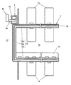
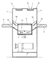
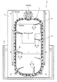
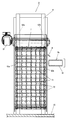
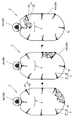
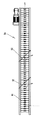
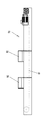
図1は本発明にかかる飲食用容器搬送装置を設置した回転寿司店の店舗内を平面的に表わした説明図、図2は同要部の拡大断面図、図3は本発明にかかる飲食用容器搬送装置の一実施形態を示す正面図、図4は同側面図、図5は本発明にかかる飲食用容器搬送装置の作動説明図である。
Embodiments of the present invention will be described below.
FIG. 1 is an explanatory view showing the interior of a rotary sushi restaurant where a container transport device for eating and drinking according to the present invention is installed, FIG. 2 is an enlarged cross-sectional view of the main part, and FIG. 3 is an eating and drinking according to the present invention. The front view which shows one Embodiment of a container conveying apparatus, FIG. 4 is the same side view, FIG. 5 is the action | operation explanatory drawing of the food-and-drink container conveying apparatus concerning this invention.
先ず図1は回転寿司の店舗内を概略的に表わしたものであって、この回転寿司の店舗内には、厨房室S1と、客室S2に配置するカウンターテーブル1a及び複数の脚付きテーブル1bと、前記厨房室S1の前面乃至各テーブル1a・1bに沿って配置した仕切ハウジング10と、この仕切ハウジング10を走行して、厨房室S1内にて飲食用容器Pの一つである皿P1に盛り合わされた寿司を各テーブル1a・1bに運ぶための無端状のフラットチエン2aを備えた移送装置2が設けられている。
First, FIG. 1 schematically shows the inside of a carousel sushi store. In the carousel sushi shop, there are a kitchen room S1, a counter table 1a arranged in the guest room S2, and a plurality of legged tables 1b. The
仕切ハウジング10は、所定間隔開けて相対向する側壁11・12と、これら両側壁11・12の上端及び下端を結ぶ上壁13及び底壁14とから断面ボックス状に形成されたものであって、厨房室S1の前面に沿って配設されて厨房室S1と客室S2とを区画する第1ハウジング部10aと、第1ハウジング部10aの長手方向両端から屈曲して客室S2内に平行に延びる第2、第3ハウジング部10b・10cから成り、各ハウジング部10a・10b・10cの上壁13に設けた凹所15内には、移送装置2のフラットチエン2aを配設する一方、第2、第3ハウジング部10b・10cにおける側壁11・12の外側方には、前記したカウンターテーブル1aと脚付きテーブル1bとを配置している。
カウンターテーブル1aの仕切ハウジング10側端部には、皿P1が縦方向に通過可能な投入口101が設けられ、また各脚付きテーブル1bの仕切ハウジング10側端部にも、皿P1が縦方向に通過可能な投入口101が設けられている。
The
At the end of the counter table 1a on the side of the
また仕切りハウジング10における前記第2、第3ハウジング部10b・10c内には
、これらハウジング部10b・10cのほぼ全長にわたって延びて、長さ方向一端が厨房室S1に設置した回収部としての回収槽16上で開口するダクト17が設けられて、このダクト17内を飲食用容器回収水路17aとし、飲食用容器回収水路17aに流す所定流速の流水により、この飲食用容器回収水路17a内に投入される皿P1やコップなどの飲食用容器Pを回収槽16まで搬送するようにしている。
Further, in the second and
以上の店舗では、各テーブル1a・1bの客が食べて空となった皿P1を投入口101に順次投入する一方、投入口101に投入することの出来ないコップなどのその他の飲食用容器Pについては、清算処理を行なう店員が投入口101の設けられている開閉扉102を開いて直接飲食用容器回収水路17a内に投入する。
そして投入された皿P1やコップなどの飲食用容器Pは、ダクト17内の飲食用容器回収水路17a内を流れる流水により流されて、回収槽16内に回収されるのであり、しかも飲食用容器回収水路17a内を流れる過程において、飲食用容器Pに付着している残飯等は、飲食用容器回収水路17a内を流れる流水と洗浄水噴射装置(図示せず)から噴射する噴射水とによって洗い落とされる。
In the above stores, the dishes P1 that have been eaten and emptied by the customers of the tables 1a and 1b are sequentially inserted into the
The introduced food and drink containers P such as the dishes P1 and the cups are washed away by running water flowing in the food and drink container collecting
本発明にかかる飲食用容器搬送装置は、前述の回収槽16に回収された皿P1などの飲食用容器Pを所定の高さ位置まで持上げるように搬送するためのものであって、次にこの飲食用容器搬送装置を説明する。
図において符号3で示す飲食用容器搬送装置は、基本的には、縦長矩形とした枠状の機体4と、この機体4内に搭載されて、上下方向に旋回する旋回機構5と、この旋回機構5と連動して上下方向に旋回して前記回収槽16に回収された飲食用容器Pを掬い上げるための掬い上げ部6と、この掬い上げ部6の外周りを囲んでこの掬い上げ部6と共に旋回する囲み部材7と、掬い上げ部6が上昇から下降に移行する時点でこの掬い上げ部6から排出される飲食用容器Pを前記した機体4の側部外方に搬出するための搬出部8が備えられている。
そして、実施形態では、飲食用容器搬送装置3における搬出部7の下流側には、飲食用容器Pを搬送しながら仕分けするための搬送仕分け装置9aと、この搬送仕分け装置9aの下流側に配置されて、この搬送仕分け装置9aから送り出されてくる皿P1を洗浄するための皿洗浄装置9bが設けられている。
The food container transport device according to the present invention is for transporting the food container P such as the dish P1 collected in the
In the figure, a food and drink container transport device denoted by
And in embodiment, it arrange | positions in the downstream of the carrying-out
飲食用容器搬送装置3を構成する機体4は、縦長矩形の枠状に組まれたものであって、図3に示すように、この機体4の下部が回収槽16内に収容される。
また飲食用容器搬送装置3を構成する旋回機構5は、機体4の上部に配置された駆動モーター51と、この駆動モーター51の駆動軸51aに連動して回転する前後一対の駆動スプロケット52a・52bと、これら駆動スプロケット52a・52bを介して機体4内を上下方向に旋回する前後一対の旋回駆動チエン53a・53bと、これら駆動チエン53a・53bの旋回駆動を案内するためのガイドレール54a・54bとが備えられ、駆動スプロケット52a・52bの回転駆動により、旋回駆動チエン53a・53bがガイドレール54a・54bを介して機体4内の下部と上部との間を旋回するようにしている。
The
The
掬い上げ部6は、回転駆動チエン52a・52b間に複数備えられているのであって、具体的には、前後回転駆動チエン52a・52bにそれぞれ組み付けた支持ブラケット55間に架設されて、回転駆動チエン52a・52bの旋回内方に配置されている。
この掬い上げ部6は、平面視略短冊状に形成された合成樹脂製の掬い上げプレート本体61と、この掬い上げプレート本体61の遊端から延長方向に斜めに延びる合成ゴム製の補助プレート部62とから構成され、プレート本体61は、上昇時乃至下降時にはほぼ水平方向を向き、上昇から下降に移行する時点で下方を向き、且つ下降から上昇に移行する時点では立ち上がるようにしている。
そしてこの掬い上げ部6が下降から上昇に移行する時点、即ち、掬い上げ部6の掬い上げプレート本体61が立ち上がっている状態から水平方向を向く時点で飲食用容器Pを掬い上げ、掬い上げ部6が上昇から下降に移行する時点、即ち、掬い上げ部6の掬い上げプレート本体61が水平方向を向いている状態から下方を向く時点で掬い上げた飲食用容器を後記する搬出部8上に排出するようにしている。
A plurality of scooping
The scooping
And when this scooping
掬い上げ部6の外周りを囲む囲み部材7は、図4に概略的に示すように、回転駆動チエン52a・52b間に所定間隔あけて架設された多数の連結杆71と、隣接する連結杆71間に所定間隔あけて掛け渡された多数の連結リンク72から略格子状に構成されて、回転駆動チエン52a・52b間において掬い上げ部6の外周りを囲むように設けられている。
搬出部8は合成樹脂製のプレートから成り、この搬出部8は、機体4内の上部に配置するととともに、機体4内から機体4の側部外方に向かって下方に傾斜するように設けられ、掬い上げ部6から排出される飲食容器Pを機体4の外側方に滑らせて後記の搬送仕分け装置9a上に搬出するようにしている。
As shown schematically in FIG. 4, the surrounding
The carry-out
一方、搬送仕分け装置9aは、図6、図7に概略的に示すように、水平方向に旋回する搬送コンベヤ91と、この搬送コンベヤ91上に所定の隙間、即ち飲食容器中の皿P1のみが通過出来る程度の隙間を開けて配置した仕分け体92が備えられ、飲食用容器Pが仕分け体92まで来た時点で、飲食用容器Pの高さの相違により仕分け体92を介して仕分けするようにしている。
具体的には、皿P1は仕分け体92の下方を通過して搬送コンベヤ91により皿洗浄装置9bに送られる一方、前記した隙間の高さよりも背の高いコップなどの飲食用容器Pは、仕分け体92により搬送コンベヤ91の側方に導かれて、搬送コンベヤ91上から排出するようにしている。
On the other hand, as schematically shown in FIGS. 6 and 7, the
Specifically, the dish P1 passes under the sorting
また皿洗浄装置9bは、図8に概略的に示すように、皿P1を搬送するための水平方向に旋回する搬送機構95と、搬送機構95により搬送される皿P1を洗浄するためのブラシ体96と、このブラシ体96を回転駆動するための駆動装置97と、搬送機構95により搬送される皿P1に洗浄液を噴射する洗浄液噴射機98が備えられ、搬送機構95により搬送される皿P1の表面に洗浄液噴射機98を介して洗浄水を噴きかけながらブラシ体96により皿P1を洗浄するようにしている。
Further, as schematically shown in FIG. 8, the
以上の構成からなる飲食用容器搬送装置3が備えられた店舗では、回収槽16に回収される飲食用容器Pは、回収槽16内に設置された機体4内の下部に順次送り込まれるのであって、この機体4内に送り込まれた飲食用容器Pは、旋回機構5を介して旋回する掬い上げ部6により順次掬い上げられて機体4内の上部までほぼ垂直方向に持上げられた後、掬い上げ部6が上昇から下降に移行する時点で搬出部8上に排出される。
そして搬出部8上に排出された飲食用容器Pは、傾斜している搬出部8上を滑って、機体4の側部外方に配置した搬送仕分け装置9aの搬送コンベヤ91上に搬出されるのであって、続いて搬送コンベヤ91に載って搬送される飲食用容器Pが仕分け体92を通過しようとする時点で、仕分け体92の下方の隙間よりも大きなコップなどの飲食容器Pは、仕分け体92の下方を通過することが出来ず、この仕分け体92の案内で搬送コンベヤ91の側方に送り出される一方、前述の隙間よりも高さの低い皿P1は、仕分け体92を通過して皿洗浄装置9bに送られて適宜洗浄される。
In the store equipped with the food
And the container P for food / drink discharged | emitted on the carrying-out
斯くして以上の飲食用容器搬送装置3では、厨房室S1の床に設置された回収槽16に回収される飲食用容器Pを、所望の高さまでほぼ垂直方向に自動的にしかも確実に搬送することが出来るので、続いて行なわれる飲食用容器の洗浄作業をスムーズに行なうことが可能となるし、それでいながら斜め上方に向けて搬送するようにしたタイプの従来の搬送
装置に比べて床面に対する装置の設置スペースも小さくて済む。
Thus, in the above-described food
以上の実施形態では、掬い上げ部6の外周りを囲んでこの掬い上げ部6と共に旋回する囲み部材7を機体4内に設けたが、本発明はこれに限定されるものではなく、例えば、掬い上げ部6を囲む周壁を機体4内に設けて、この周壁の内周面に沿って掬い上げ部6を旋回させるようにしてもよい。
In the above embodiment, the surrounding
16 回収槽
3 飲食用容器搬送装置
4 機体
5 旋回機構
52a・52b 駆動スプロケット
53a・53b 旋回駆動チエン
6 掬い上げ部
7 囲み部材
8 搬出部
S1 厨房
P 飲食用容器
P1 皿
Claims (2)
Priority Applications (1)
| Application Number | Priority Date | Filing Date | Title |
|---|---|---|---|
| JP2011036510A JP2012170663A (en) | 2011-02-23 | 2011-02-23 | Food container carrier |
Applications Claiming Priority (1)
| Application Number | Priority Date | Filing Date | Title |
|---|---|---|---|
| JP2011036510A JP2012170663A (en) | 2011-02-23 | 2011-02-23 | Food container carrier |
Publications (1)
| Publication Number | Publication Date |
|---|---|
| JP2012170663A true JP2012170663A (en) | 2012-09-10 |
Family
ID=46974127
Family Applications (1)
| Application Number | Title | Priority Date | Filing Date |
|---|---|---|---|
| JP2011036510A Pending JP2012170663A (en) | 2011-02-23 | 2011-02-23 | Food container carrier |
Country Status (1)
| Country | Link |
|---|---|
| JP (1) | JP2012170663A (en) |
Citations (3)
| Publication number | Priority date | Publication date | Assignee | Title |
|---|---|---|---|---|
| US1864064A (en) * | 1930-02-03 | 1932-06-21 | Automatic Food Machinery Corp | Dishwashing machine |
| JPS5535036U (en) * | 1978-08-30 | 1980-03-06 | ||
| JP2002192081A (en) * | 2000-12-27 | 2002-07-10 | Kura Corporation:Kk | Container collection device in restaurants |
-
2011
- 2011-02-23 JP JP2011036510A patent/JP2012170663A/en active Pending
Patent Citations (3)
| Publication number | Priority date | Publication date | Assignee | Title |
|---|---|---|---|---|
| US1864064A (en) * | 1930-02-03 | 1932-06-21 | Automatic Food Machinery Corp | Dishwashing machine |
| JPS5535036U (en) * | 1978-08-30 | 1980-03-06 | ||
| JP2002192081A (en) * | 2000-12-27 | 2002-07-10 | Kura Corporation:Kk | Container collection device in restaurants |
Similar Documents
| Publication | Publication Date | Title |
|---|---|---|
| CN103237488B (en) | conveyor dishwasher | |
| CN103501676B (en) | Conveying apparatus for feeding washed parts to a conveyor warewasher | |
| KR101992762B1 (en) | Automatic dishwashing system that separates dishes and plates separately | |
| JP2004313501A (en) | Circulating conveyor for food and drink | |
| KR101034278B1 (en) | Food Cooling Conveyor | |
| KR101444762B1 (en) | A dish washer system | |
| JP5744778B2 (en) | Dish sorter and dish washing system | |
| JP4173188B1 (en) | Sushi counter | |
| KR101648797B1 (en) | Automatic box washing machine | |
| CN112773297B (en) | Automatic meal collecting device | |
| JP4711047B2 (en) | Vegetable cleaning equipment | |
| JP2020059577A (en) | Tea-processing vertical bucket conveyor | |
| JP7120771B2 (en) | Dish washing equipment | |
| JP2000300232A (en) | Transfer device | |
| JP4324270B2 (en) | Plum seed pretreatment equipment using bucket elevator | |
| CN115515869A (en) | Drive station | |
| JP2006008288A (en) | Cleaning device in rotation eating and drinking container transport device | |
| CN113475992A (en) | Integrated tableware feeding, soaking and deslagging all-in-one machine | |
| JP2019201889A (en) | Tableware recovery system | |
| US5701806A (en) | Installation for the preparation of bread dough portions | |
| CN119142741B (en) | Dining basin conveying device of robot intelligent restaurant | |
| JP2001190475A (en) | Dishwasher | |
| CN206852569U (en) | Wash dishes line | |
| JP3543171B2 (en) | Bottle processing equipment for recycling | |
| CN218588516U (en) | Automatic clean dining table system |
Legal Events
| Date | Code | Title | Description |
|---|---|---|---|
| A621 | Written request for application examination |
Free format text: JAPANESE INTERMEDIATE CODE: A621 Effective date: 20140128 |
|
| A977 | Report on retrieval |
Free format text: JAPANESE INTERMEDIATE CODE: A971007 Effective date: 20140912 |
|
| A131 | Notification of reasons for refusal |
Free format text: JAPANESE INTERMEDIATE CODE: A131 Effective date: 20140918 |
|
| A02 | Decision of refusal |
Free format text: JAPANESE INTERMEDIATE CODE: A02 Effective date: 20150128 |