JP2012171365A - Vehicle starting system - Google Patents
Vehicle starting system Download PDFInfo
- Publication number
- JP2012171365A JP2012171365A JP2011031804A JP2011031804A JP2012171365A JP 2012171365 A JP2012171365 A JP 2012171365A JP 2011031804 A JP2011031804 A JP 2011031804A JP 2011031804 A JP2011031804 A JP 2011031804A JP 2012171365 A JP2012171365 A JP 2012171365A
- Authority
- JP
- Japan
- Prior art keywords
- portable device
- slot
- vehicle
- code
- state
- Prior art date
- Legal status (The legal status is an assumption and is not a legal conclusion. Google has not performed a legal analysis and makes no representation as to the accuracy of the status listed.)
- Granted
Links
Images




Landscapes
- Lock And Its Accessories (AREA)
Abstract
【課題】安全性に優れ、使い勝手が良好で、安価に構成し得る車両用始動システムを提供する。
【解決手段】車両用始動システム1は、IDコードを無線送信可能なトランスポンダ10が内蔵された携帯機2と、トランスポンダ10を駆動するための駆動電波を送信するコイルアンテナ31を有し携帯機2が送信したIDコードを無線受信可能なトランスポンダ送受信機30と、携帯機2からのIDコードを予め登録されているマスターコードと照合するマイコン40(照合手段)とを備える。携帯機2には、エンジンを始動させ又は電源をオンするためのプッシュSW21(操作スイッチ)が設けられる。車両3には、トランスポンダ送受信機30から送信された駆動電波がトランスポンダ10により受信されるよう、コイルアンテナ31に近接した位置にて携帯機2の挿し込みを許容するスロット4が設けられる。
【選択図】図4A starting system for a vehicle that is excellent in safety, easy to use, and can be configured at low cost.
A vehicle start system includes a portable device having a built-in transponder capable of wirelessly transmitting an ID code, and a coil antenna that transmits a driving radio wave for driving the transponder. Is provided with a transponder transceiver 30 capable of wirelessly receiving the ID code transmitted by the microcomputer 40 and a microcomputer 40 (verification means) for collating the ID code from the portable device 2 with a master code registered in advance. The portable device 2 is provided with a push SW 21 (operation switch) for starting the engine or turning on the power. The vehicle 3 is provided with a slot 4 that allows the portable device 2 to be inserted at a position close to the coil antenna 31 so that the drive radio wave transmitted from the transponder transceiver 30 is received by the transponder 10.
[Selection] Figure 4
Description
本発明は、車両用の電源切替システムやエンジン始動システムを含んで構成される車両用始動システムに関し、特に携帯機の操作により、IDコードの受理認証及び操作スイッチの操作が有効化されることを条件として、電源のオン/オフやエンジンの始動/停止がなされる車両用始動システムに関する。 The present invention relates to a vehicular start system including a vehicular power supply switching system and an engine start system. In particular, the operation of a portable device validates ID code acceptance authentication and operation of an operation switch. The present invention relates to a vehicle start system in which the power is turned on / off and the engine is started / stopped.
車両用始動システムとして、車室内に設けられた室内発信機により車室内に検知エリアが形成され、携帯機から受信したデータ信号に含まれるIDコードの照合が一致したとき、登録された携帯機が車室内にあるものと判定し、この状態で、車両に設けられたエンジンスイッチを押圧操作することでエンジンを始動可能とするものが知られている(例えば、下記特許文献1、2参照)。
As a vehicle start-up system, when a detection area is formed in the vehicle interior by an indoor transmitter provided in the vehicle interior, and the collation of the ID code included in the data signal received from the mobile device matches, the registered mobile device is It is known that the engine can be started by determining that the vehicle is in the passenger compartment and pressing an engine switch provided in the vehicle in this state (for example, see
しかし、上記特許文献1、2に記載された車両用始動システムでは、車室内に携帯機があるか否かを判断するためのリクエスト信号を発信する複数の室内発信機が必要であり、始動システムが高価となって車両搭載性が必ずしも良好ではなかった。また、エンジンを始動するためのエンジンスイッチが車両に設けられていたため、例えば携帯機を車室内に置き忘れた場合等には他人が容易にエンジンを始動させ得るものであった。さらに、携帯機の電池が切れた場合に限って携帯機をエンジンスイッチにかざしてトラポン照合を行うという、通常とは異なる操作(単に携帯機を身に着けている以外の操作)を行う必要があり、操作方法についてユーザを混乱させるおそれもあった。
However, the vehicle start systems described in
本発明は、上記問題に対処するためになされたものであり、その目的は、安全性に優れ、使い勝手が良好で、しかも安価に構成し得る車両用始動システムを提供することにある。 The present invention has been made to cope with the above problems, and an object of the present invention is to provide a vehicle start system that is excellent in safety, easy to use, and can be configured at low cost.
上記目的を達成するため、本発明の車両用始動システムは、IDコードを無線送信可能なトランスポンダが内蔵された携帯機と、車両に搭載され、トランスポンダを駆動するための駆動電波を送信するコイルアンテナを有し、携帯機が無線送信したIDコードを無線受信可能なトランスポンダ送受信機と、携帯機からのIDコードを予め登録されているマスターコードと照合する照合手段と、を備え、
携帯機には、エンジンを始動/停止させ、又は電源をオン/オフするためのプッシュ式の操作スイッチが設けられ、車両には、トランスポンダ送受信機から送信された駆動電波が携帯機のトランスポンダにより受信されるよう、コイルアンテナに近接した位置にて携帯機の挿し込みを許容するスロットが設けられ、
携帯機がスロットに挿し込まれ、かつ、携帯機の操作スイッチがプッシュ状態となったとき、コイルアンテナからの駆動電波を受けて携帯機からトランスポンダ送受信機にIDコードや電源のスイッチ状態が無線送信され、照合手段によりIDコードの受理認証がされることを条件として、エンジンが始動可能、又は電源がオン可能とされていることを特徴とする。この場合、例えば、携帯機がスロットに挿し込まれた状態では、操作スイッチがスロットの外部に露出するように構成されており、携帯機がスロットに挿し込まれ、操作スイッチがプッシュ操作され、照合手段によりIDコードの受理認証がされたとき、エンジンが始動、又は電源がオンとされる構成にすることができる。なお、「電源」のオンとは、電源ポジションがACC、IGオンになることを意味し、例えば操作スイッチが操作される度に、オフ、ACC、IGオンがこの順に切り替えられるような構成とすることができる。
In order to achieve the above object, a vehicle start system according to the present invention includes a portable device incorporating a transponder capable of wirelessly transmitting an ID code, and a coil antenna that is mounted on the vehicle and transmits a driving radio wave for driving the transponder. A transponder transceiver capable of wirelessly receiving an ID code wirelessly transmitted by a portable device, and a collating means for collating the ID code from the portable device with a pre-registered master code,
The portable device is provided with a push-type operation switch for starting / stopping the engine or turning the power on / off, and the vehicle receives the driving radio wave transmitted from the transponder transceiver by the transponder of the portable device. So that a slot allowing insertion of the portable device at a position close to the coil antenna is provided,
When the portable device is inserted into the slot and the operation switch of the portable device is in the push state, the ID code and the power switch state are wirelessly transmitted from the portable device to the transponder transceiver in response to the drive radio wave from the coil antenna. The engine can be started or the power can be turned on under the condition that the ID code is accepted and authenticated by the verification means. In this case, for example, when the portable device is inserted into the slot, the operation switch is exposed to the outside of the slot, the portable device is inserted into the slot, the operation switch is pushed, and verification is performed. When the ID code is received and authenticated by the means, the engine can be started or the power can be turned on. Note that “on” of the power supply means that the power supply position is ACC and IG on. For example, every time the operation switch is operated, off, ACC, and IG on are switched in this order. be able to.
本発明の車両用始動システムでは、携帯機のトランスポンダから車両側のトランスポンダ送受信機に向けてIDコードが無線送信され、照合手段によりそのIDコードと予め登録されているマスターコードとの照合が行われる(トラポン照合)。これにより、車室内において携帯機があるか否かを判断するためのリクエスト信号を発信する複数の室内発信機が不要となるため、始動システムのコストダウンを図ることができ、車両搭載性の向上を図ることができる。また、携帯機に、エンジンを始動/停止させ、又は電源をオン/オフするためのプッシュ式の操作スイッチが設けられている。これにより、ユーザが携帯機を携帯する限り、他人が操作スイッチを操作することは一切できないため、安全性の向上を図ることができる。さらに、携帯機の電池が切れた場合でも、通常時の操作と同様に携帯機をスロットに挿し込んで操作スイッチをプッシュ状態とすればエンジンを始動/停止、又は電源をオン/オフすることができるため、操作方法に関してユーザが混乱するおそれを解消することもできる。 In the vehicle starting system of the present invention, an ID code is wirelessly transmitted from a transponder of a portable device to a transponder transmitter / receiver on the vehicle side, and collation between the ID code and a master code registered in advance is performed. (Trapone verification). This eliminates the need for a plurality of indoor transmitters that transmit request signals for determining whether or not there is a portable device in the vehicle interior, thereby reducing the cost of the starter system and improving vehicle mountability. Can be achieved. The portable device is provided with a push-type operation switch for starting / stopping the engine or turning on / off the power. As a result, as long as the user carries the portable device, other people cannot operate the operation switch at all, and thus safety can be improved. Further, even when the battery of the portable device is exhausted, the engine can be started / stopped or the power can be turned on / off by inserting the portable device into the slot and pushing the operation switch in the same manner as in normal operation. Therefore, it is possible to eliminate the possibility of the user being confused about the operation method.
なお、携帯機がスロットに挿し込まれた状態で、操作スイッチがスロットの外部に露出するように構成した場合には、露出部位を指で摘むことで携帯機をスロット内から容易に抜き出すことができるようになる。 When the operation switch is exposed to the outside of the slot while the portable device is inserted into the slot, the portable device can be easily removed from the slot by picking the exposed part with a finger. become able to.
また、携帯機がスロットに挿し込まれた状態では、操作スイッチがスロット内に収納され、携帯機の挿し込み時に操作スイッチがスロットのカバー部との接触によりプッシュ動作されるように構成されており、携帯機がスロットに挿し込まれたとき、操作スイッチのプッシュ動作に応じて照合手段によりIDコードの照合が開始され、IDコードの受理認証がされたとき、エンジンが始動される構成とすることができる。さらに、車両のブレーキペダルが踏み込まれることなく携帯機がスロットに挿し込まれたとき、操作スイッチのプッシュ動作に応じて照合手段によりIDコードの照合が開始され、IDコードの受理認証がされたとき、電源がオンされる構成とすることもできる。
また、運転席ドアの開閉や車両のブレーキペダルが踏み込まれたことをトリガに、定期的に車両側のコイルアンテナから電波を送信することで、携帯機がスロットに挿し込まれたことを検出し、エンジンが始動される構成とすることができる。さらに、車両のブレーキペダルが踏み込まれることなく携帯機がスロットに挿し込まれ、IDコードの受理認証がされたとき、電源がオンされる構成とすることもできる。
In addition, when the portable device is inserted into the slot, the operation switch is housed in the slot, and when the portable device is inserted, the operation switch is pushed by contact with the cover of the slot. When the portable device is inserted into the slot, the ID code verification is started by the verification means according to the push operation of the operation switch, and the engine is started when the ID code is accepted and authenticated. Can do. Furthermore, when the portable device is inserted into the slot without depressing the brake pedal of the vehicle, ID code verification is started by the verification means in accordance with the push operation of the operation switch, and ID code acceptance authentication is performed The power supply can be turned on.
In addition, triggered by the opening / closing of the driver's seat door or the depression of the vehicle's brake pedal, it is detected that the portable device is inserted into the slot by periodically transmitting radio waves from the vehicle's coil antenna. The engine can be started. Furthermore, the power supply may be turned on when the portable device is inserted into the slot without stepping on the brake pedal of the vehicle and the ID code is accepted.
これによれば、携帯機をスロットに挿し込むだけで、操作スイッチがスロットのカバー部との接触によりプッシュ状態となる。このため、エンジンを始動、又は電源をオンするための操作が簡便となり、携帯機における使い勝っての向上を図ることができる。なお、携帯機がスロットに挿し込まれない状態から挿し込まれた状態へ変化したときに携帯機の挿し込まれた状態を検知することで、携帯機の操作スイッチを操作しなくても、操作スイッチが操作された場合と同様の処理が実行されるような構成とすることもできる。 According to this, only by inserting the portable device into the slot, the operation switch is brought into a push state by contact with the cover portion of the slot. For this reason, the operation for starting the engine or turning on the power becomes simple, and the usability of the portable device can be improved. In addition, by detecting the inserted state of the portable device when the portable device changes from the state not inserted into the slot to the inserted state, the operation can be performed without operating the operation switch of the portable device. A configuration in which processing similar to that performed when the switch is operated may be performed.
また、スロットには、携帯機の抜き出しを許容するロック解除状態と、携帯機の抜き出しを阻止するロック状態とのいずれかの状態に切り替えられる携帯機ロック機構が設けられている構成とすることができる。この場合、携帯機ロック機構は、例えば携帯機がスロットに挿し込まれて照合手段によりIDコードの受理認証がされたタイミング、エンジンが始動したタイミング、及び電源がオンとなったタイミングのうちいずれかのタイミングでロック解除状態からロック状態に切り替えられると好適である。 In addition, the slot may be provided with a portable device lock mechanism that can be switched between a lock release state that allows removal of the portable device and a lock state that prevents removal of the portable device. it can. In this case, for example, the portable device lock mechanism is one of the timing when the portable device is inserted into the slot and the ID code is accepted and verified by the verification unit, the timing when the engine is started, and the timing when the power is turned on. It is preferable to switch from the unlocked state to the locked state at this timing.
これによれば、例えば車両の走行中において、携帯機がスロットから抜けないようにすることができ、携帯機がスロットから抜け落ちる、あるいは誤って抜き出されること等に起因して不意にエンジンが停止し、あるいは電源がオフしてしまう状況を回避することができる。 According to this, for example, while the vehicle is running, the portable device can be prevented from being removed from the slot, and the engine is unexpectedly stopped due to the portable device falling out of the slot or being accidentally pulled out. Alternatively, it is possible to avoid a situation where the power is turned off.
この場合、車両の停車状態で携帯機ロック機構がロック状態からロック解除状態に切り替えられ、該ロック解除状態で携帯機がスロット内から抜き出されたとき、エンジンが停止され、又は電源がオフされる構成とすることができる。なお、「車両の停車状態」とは、シフトポジションが「P」(パーキング)レンジに切り替えられた状態にあることが最も望ましいが、これに限らず、例えば車速がゼロであるとき、ブレーキペダルが踏み込まれているとき等を広く含めることができる。なお、これらの基本動作として、車両の停車状態(シフトポジションが「P」レンジ)で操作スイッチがプッシュ操作されたときに電源がオフされ、作動中のエンジンが停止される構成を採用することができる。 In this case, when the portable device locking mechanism is switched from the locked state to the unlocked state while the vehicle is stopped, and the portable device is pulled out from the slot in the unlocked state, the engine is stopped or the power is turned off. It can be set as a structure. The “stop state of the vehicle” is most preferably a state in which the shift position is switched to the “P” (parking) range, but is not limited to this. For example, when the vehicle speed is zero, the brake pedal is It can include a wide range of times when it is depressed. As these basic operations, a configuration is adopted in which the power is turned off when the operation switch is pushed while the vehicle is stopped (shift position is in the “P” range), and the operating engine is stopped. it can.
これによれば、エンジンを停止、又は電源をオフするための操作がより簡便となり、携帯機における使い勝っての向上を図ることができる。 According to this, the operation for stopping the engine or turning off the power becomes simpler, and the usability of the portable device can be improved.
また、携帯機には、車両のドア制御部に対する無線通信によりドアをロック状態に切り替えるドアロックスイッチ、及びロック解除状態に切り替えるドアアンロックスイッチが設けられており、携帯機がスロットに挿し込まれた状態では、ドアロックスイッチ及びドアアンロックスイッチが該スロットにより外部から遮蔽されるように構成されているとよい。 In addition, the portable device is provided with a door lock switch that switches the door to a locked state by wireless communication with the door control unit of the vehicle, and a door unlock switch that switches to the unlocked state, and the portable device is inserted into the slot. In this state, the door lock switch and the door unlock switch may be configured to be shielded from the outside by the slot.
これによれば、携帯機がスロットに挿し込まれた状態において、ドアロックスイッチ又はドアアンロックスイッチが誤操作される事態を良好に回避することができる。 According to this, in a state where the portable device is inserted into the slot, it is possible to favorably avoid a situation in which the door lock switch or the door unlock switch is erroneously operated.
また、スロットは、携帯機の挿し込み口となる開口部の横断面積を最大として該携帯機の挿し込み方向に向かうほど該スロットの横断面積が小さくなるように設定されていると好適である。これによれば、携帯機がスロットに挿し込みやすくなるため、操作性の向上を図ることができる。なお、スロットは、その底面にて外部に連通する貫通孔を有するように構成することができる。これによれば、スロット内に浸入した水(水滴)やゴミ等の異物をスロットの外側へ良好に排出できるため、スロット内を清潔に保つことができる。また、スロット内に、挿し込まれた携帯機をスロットの外部に向けて押し出す押し出し機構を設けるようにしてもよい。これによれば、携帯機をスロット内から容易に取り出すことができるようになる。 In addition, it is preferable that the slot is set so that the cross-sectional area of the slot becomes smaller as the cross-sectional area of the opening serving as the insertion port of the portable device is maximized and the direction of insertion of the portable device is increased. According to this, since the portable device can be easily inserted into the slot, the operability can be improved. The slot can be configured to have a through hole communicating with the outside on the bottom surface. According to this, since foreign matter such as water (water droplets) and dust that has entered the slot can be discharged well to the outside of the slot, the inside of the slot can be kept clean. Moreover, you may make it provide the extrusion mechanism which pushes the portable machine inserted in the slot toward the exterior of a slot. According to this, the portable device can be easily taken out from the slot.
また、スロットの開口部又は挿し込まれた携帯機の周囲には、携帯機や該携帯機の操作スイッチの位置を点灯によりユーザに視認させるインジケータやイルミネーションが配置されているように構成することができる。この場合、インジケータやイルミネーションは、車両状態に応じて照明色又は点灯態様が変更可能に設定されていると好適である。例えば、ユーザが車両に乗り込んで携帯機をスロットに挿し込むまでは青色で点灯し、エンジンを停止(電源をオフ)してから携帯機を抜くまでは青色で点滅し、始動システムに何らかの異常が発生したときは赤色で点滅するような構成とすることが考えられる。 In addition, an indicator or illumination that allows the user to visually recognize the position of the portable device or the operation switch of the portable device by lighting is arranged around the opening of the slot or the inserted portable device. it can. In this case, it is preferable that the indicator or illumination is set so that the illumination color or lighting mode can be changed according to the vehicle state. For example, it lights in blue until the user gets into the vehicle and inserts the portable device into the slot, blinks blue until the portable device is removed after the engine is stopped (power is turned off), and there is an abnormality in the starting system. It is conceivable to adopt a configuration that flashes red when it occurs.
これによれば、例えば夜間における携帯機の操作性を著しく向上させることができる。 According to this, the operability of the portable device at night can be remarkably improved, for example.
また、携帯機の形状はスロットに挿し込みやすいように、スロットに挿し込まれる先端側が鋭角状又は流線状の先細り形状とされているとよい。また、携帯機に、ドアロックスイッチ及びドアアンロックスイッチが設けられる場合には、それらのスイッチと操作スイッチとの色や形状等の外観を変えることで各スイッチを容易に識別できるようになる。 In addition, the shape of the portable device may be such that the tip side inserted into the slot is an acute angle or streamlined tapered shape so that it can be easily inserted into the slot. When the door lock switch and the door unlock switch are provided in the portable device, each switch can be easily identified by changing the appearance of the color and shape of these switches and operation switches.
以下、本発明の実施形態について図面を用いて説明する。 Hereinafter, embodiments of the present invention will be described with reference to the drawings.
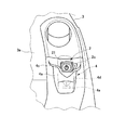
図1は、本発明の車両用始動システム1(図4参照)を構成する携帯機2が、車両3のスロット4に挿し込まれた状態を示したものであり、図2は携帯機2を示し、図3はスロット4を示している。車両用始動システム1は、図4のブロック図で示すように、携帯機2に加え、車両3側のトランスポンダ送受信機30、マイクロコンピュータ40(以下、単にマイコン40という)、記憶装置50などを含んで構成されている。マイコン40は、エンジン制御部60、ドア制御部70等の各制御部(制御回路)と車内LAN100を介して相互に通信可能に接続されている。
FIG. 1 shows a state in which a
トランスポンダ送受信機30は、スロット4の裏側に組み込まれている。トランスポンダ送受信機30は、携帯機2のトランスポンダ10を駆動するための駆動電波を送信するコイルアンテナ31を有し、マイクロコンピュータで構成される主回路部32(駆動電波発生回路部)と、送受信回路及び周知の復調回路を含んで構成される無線通信回路部33(送受信回路部)とからなる。主回路部32は、コイルアンテナ31を介して、トランスポンダ送受信機30外に向けて磁界(例えばLF(長波)帯域の電磁波)を発生させる。
The
無線通信回路部33は、携帯機2からIDコードを含むデータ(トランスポンダ信号)を受信した場合に、これを復調した上で主回路部32に送る。主回路部32は、復調されたデータからIDコードを読み出し、これをマイコン40へ送信する。
When receiving the data (transponder signal) including the ID code from the
マイコン40(照合手段)は、CPU,ROM,RAM,入出力部(I/O)などを主要構成部品としており、ROM等に記憶されているIDコード照合処理プログラム(図示省略)を始めとする各種処理プログラムを繰り返し実行する。具体的には、マイコン40は、トランスポンダ送受信機30を経由して送信された携帯機2からのIDコードを、記憶装置50に記憶されている車両に固有の照合用のマスターコード(マスターID)と比較し、両IDコードの照合が一致(受理認証)するか否かを判定する。
The microcomputer 40 (collation means) has a CPU, ROM, RAM, input / output unit (I / O) and the like as main components, and includes an ID code collation processing program (not shown) stored in the ROM or the like. Various processing programs are executed repeatedly. Specifically, the
マイコン40には、ユーザがブレーキペダルを踏んだときマイコン40に対してオン信号が入力されるようにストップランプSW41が接続されるとともに、マイコン40からの駆動信号が出力されるようにACCリレー42、IGリレー43等の電源リレーや携帯機ロック機構44が接続されている。ACCリレー42、IGリレー43及び携帯機ロック機構44については後述する。
A stop lamp SW41 is connected to the
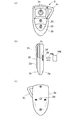
携帯機2(無線携帯キー、電子キー)は、トランスポンダ送受信機30との間でデータを送信可能な携帯型無線装置としての機能を果たすものであり、図2(a)〜2(c)に示すように、スロット4に挿し込まれる先端側が流線状(あるいは鋭角状)の先細り形状とされ、この先端側に例えば無線通信用のアンテナ13が内蔵されている(図4参照)。携帯機2は、ケース体2a、蓋体2b及びストラップ2cを含んで構成されている。
The portable device 2 (wireless portable key, electronic key) functions as a portable wireless device capable of transmitting data to and from the
携帯機2の内部には、図4に示すように、IDコードを記憶するためのメモリ11aを有しマイクロコンピュータで構成される主回路部11と、周知の変調回路を含んで構成される無線通信回路部12(送信回路部)とからなるトランスポンダ10が内蔵されている。
As shown in FIG. 4, the
トランスポンダ10は、トランスポンダ送受信機30で発生した駆動電波を受けると、電磁誘導の法則に基づいて主回路部11に誘起電流を発生させる。主回路部11は、この誘起電流を電気エネルギーとして使用し(例えば電源用コンデンサによる充・放電)、メモリ11aに記憶されているIDコードを含むデータを無線通信回路部12を介してトランスポンダ送受信機30へ送信する。
When receiving the driving radio wave generated by the
この場合、携帯機2をスロット4に挿し込むと(両者間の距離が例えば10cm以内となるように)、トランスポンダ10がトランスポンダ送受信機30で発生した駆動電波を受けるようになり、主回路部11がIDコードを含むデータをトランスポンダ送受信機30へ向けて送信する。
In this case, when the
これに対して、携帯機2をスロット4から抜き出すと(両者間の距離が例えば10cmを超えるように)、トランスポンダ10がトランスポンダ送受信機30で発生した駆動電波を受けなくなり、以降は主回路部11がIDコードを含むデータをトランスポンダ送受信機30へ向けて送信しなくなる。
On the other hand, when the
携帯機2には、図2(a)及び図4に示すように、プッシュSW21、ドアロックSW22及びドアアンロックSW23が設けられている。各SW21〜23は、蓋体2bから露出した状態で一列に配置されている。プッシュSW21(操作スイッチ)は、そのオン信号をマイコン40へ送信し、これを受けマイコン40は、エンジン制御部60を介してエンジン始動部61を始動可能、又はACCリレー42、IGリレー43等の電源用リレーを駆動可能とされている。
As shown in FIGS. 2A and 4, the
ドアロックSW22は、そのオン信号をマイコン40へ送信し、これを受けマイコン40は、ドア制御部70を介してドアロック機構71をロック状態に切り替える。ドアアンロックSW23は、そのオン信号をマイコン40へ送信し、これを受けマイコン40は、ドア制御部70を介してドアロック機構71をロック解除状態に切り替える。
The
なお、携帯機2がスロット4に挿し込まれた状態では、プッシュSW21のみがスロット4の外部に露出し、ドアロックSW22及びドアアンロックSW23がスロット4により外部から遮蔽されるように構成されている。
When the
スロット4は、図3に示すように、運転席に対応するインストルメントパネル3aに設けられ、携帯機2の挿し込みを許容するポケット状のカバー部4aを備えている。カバー部4aは、携帯機2の挿し込み口となる開口部4bの横断面積を最大として該携帯機2の挿し込み方向に向かうほどスロット4の横断面積(内部の横断面積)が小さくなるように設定されている。これにより、携帯機2をスロット4に挿し込みやすい仕様となっている。
As shown in FIG. 3, the
開口部4bには、インジケータ4cが配置されている。インジケータ4cは、例えば夜間等におけるユーザの車両3への乗り込み時に(例えばドア制御部70がドアアンロック制御信号を受信したとき)、マイコン40により点灯されるように設定されている。これにより、ユーザはインジケータ4cの点灯により開口部4bの位置を視認できるので、携帯機2のスロット4への挿し込みが極めて容易となる。
An
スロット4に対応するインストルメントパネル3aの裏面側には、トランスポンダ送受信機30のコイルアンテナ31に加えて、携帯機ロック機構44が設けられている(図4参照)。携帯機ロック機構44は、例えばプランジャ44a(図2(b)参照)、及びプランジャ44aを駆動する電磁ソレノイド44bを含んで構成され、マイコン40の駆動信号に応じてプランジャ44aをケース体2aに形成された係合孔2dに係合させ、あるいは離脱させる。
In addition to the coil antenna 31 of the
すなわち、プランジャ44aが係合孔2dに係合すると、携帯機2のスロット4からの抜き出しが阻止されるロック状態となり、プランジャ44aが係合孔2dから離脱すると、携帯機2のスロット4からの抜き出しが許容されるロック解除状態となる。なお、係合孔2dに加えて又は代えて、例えばケース体2aの両側面にそれぞれ係合孔2d’を形成し(図2(b)の破線参照)、各係合孔2d’に係合・離脱可能なプランジャを設けるようにしてもよい。
That is, when the
携帯機ロック機構44は、携帯機2がスロット4に挿し込まれ、プッシュSW21の操作に伴ってマイコン40によりIDコードの受理認証がされたタイミングで、マイコン40からの駆動信号に応じてロック解除状態からロック状態に切り替えられる。一方、エンジンの作動中に車両が停止状態とされ、さらにシフトポジションが「P」レンジに切り替えられると、携帯機ロック機構44は、マイコン40からの駆動信号に応じてロック状態からロック解除状態に切り替えられるようになっている。
The portable
なお、携帯機ロック機構44は、プッシュSW21の操作に伴ってエンジン始動部61が始動したタイミング(エンジンが始動したタイミング)、及びACCリレー41、IGリレー42等の電源用リレーが駆動したタイミング(電源がオンしたタイミング)のうちいずれかのタイミングで、マイコン40からの駆動信号に応じて、ロック解除状態からロック状態に切り替えられるような構成とすることもできる。
Note that the portable
次に、上記のように構成された実施例1の作動について説明する。最初に電源をオンする場合について説明する。ユーザが車外でドアアンロックSW23を押すと、ロック状態にあるドアロック機構71がロック解除状態となり、車両3に乗車できるようになる。携帯機2をスロット4に挿し込み、ブレーキを踏まずにプッシュSW21を押すと、プッシュSW21はオン信号をマイコン40へ送信する。
Next, the operation of the first embodiment configured as described above will be described. A case where the power is turned on first will be described. When the user presses the
マイコン40は、IDコードの照合を開始しIDコードが一致(受理認証)したとき、電源ポジションがオフならACCリレー42をオンする一方で、既に電源ポジションがACCならIGリレー43をオンする。
When the
次にエンジンをスタートさせる場合について説明する。車両3への乗車後、携帯機2をスロット4に挿し込み、ブレーキを踏みながらプッシュSW21を押すと、プッシュSW21及びストップランプSW41は、それぞれオン信号をマイコン40へ送信する。
Next, the case where the engine is started will be described. After getting on the
マイコン40は、IDコードの照合を開始しIDコードが一致(受理認証)したとき、ACCリレー42をオンした後、IGリレー43をオンするとともに、エンジン制御部60へエンジンスタート要求信号を送信する。エンジン制御部60がエンジン始動部61を始動させることで、エンジンが始動する。
When the
次にエンジンを停止させる場合について説明する。エンジンの作動中に車両を停止状態とし、さらにシフトポジションを「P」レンジに切り替えてからプッシュSW21を押すと、ブレーキペダル操作の有無にかかわらず、マイコン40は電源ポジションをオフする。これにより、エンジンが停止状態となる。車両3からの降車後、ドアロックSW22を押すと、ドアロック機構71がロック状態となり、ドアが開かなくなる。
Next, a case where the engine is stopped will be described. When the vehicle is stopped during the operation of the engine and the shift position is switched to the “P” range and then the
上記実施例1では、携帯機2のトランスポンダ10から車両3側のトランスポンダ送受信機30に向けてIDコードが無線送信され、マイコン40によりそのIDコードと予め登録されているマスターコードとの照合が行われる(トラポン照合)。これにより、車室内において携帯機2があるか否かを判断するためのリクエスト信号を発信する複数の室内発信機が不要となるため、始動システムのコストダウンを図ることができ、車両搭載性の向上を図ることができる。また、携帯機2に、エンジンを始動させ、又は電源をオンする操作スイッチとしてのプッシュSW21が設けられている。これにより、ユーザが携帯機2を携帯する限り、他人がプッシュSW21を操作することは一切できないため、安全性の向上を図ることができる。さらに、携帯機2の電池が切れた場合でも、通常時の操作と同様に携帯機2をスロット4に挿し込んでプッシュSW21をプッシュ状態とすればエンジンを始動、又は電源をオンすることができるため、操作方法に関してユーザが混乱するおそれを解消することもできる。
In the first embodiment, the ID code is wirelessly transmitted from the
(変形例1)
上記実施例1では、プッシュSW21(操作スイッチ)が、そのオン信号をマイコン40へ無線で送信するように構成されていたが、これに代えて例えば図5に示すように、携帯機2をスロット4に挿し込むと、携帯機2側の接点端子C1とスロット4側の接点端子C2とが接触し合い、これによりプッシュSW21がそのオン信号をマイコン40へ有線で送信するように構成することもできる。
(Modification 1)
In the first embodiment, the push SW 21 (operation switch) is configured to wirelessly transmit the ON signal to the
(変形例2)
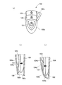
また、上記実施例1では、図2(a)に示したように、携帯機2を正面から見た場合に、ドアロックSW22及びドアアンロックSW23の各絵柄の上下が携帯機2の上下(プッシュSW21を上側とする)と一致するように構成されていたが、これに代えて例えば図6の携帯機2’に示すように、ドアロックSW22及びドアアンロックSW23の各絵柄を上下逆さまにしてもよい。
(Modification 2)
In the first embodiment, as shown in FIG. 2A, when the
ドアロックSW22、ドアアンロックSW23を操作するときは、携帯機2’の先端を車両3に向けることが一般的であるため、上記のように各絵柄を逆さまにすることで、携帯機2’の先端を車両3に向けたとき各絵柄の内容の理解が容易となる。その他の構成は、上記実施例1と同じであるため、上記実施例1と同じ機能を果たす部材には同一の符号を付して説明は省略する。
When operating the door lock SW22 and the door unlock SW23, it is common to point the tip of the
上記実施例1では、車両の停車状態でプッシュSW21のプッシュ操作に伴って作動中のエンジンが停止状態となり、また電源がオフするように構成されていたが、これに加えて又は代えて、例えば車両が停止状態となることでロック解除状態となった携帯機2をスロット4から抜き出すことで、エンジンが停止状態となり、また電源がオフするような構成とすることもできる。
In the first embodiment, the engine that is in operation is stopped in accordance with the push operation of the
この実施例2では、マイコン40が携帯機2からIDコードを定期的に受信しマスターコードとの照合を定期的に実行するように構成されている。携帯機2をスロット4から抜き出すと、マイコン40が携帯機2からIDコードを受信できなくなるため、以後はIDコードの受理認証を行うことができなくなる。この場合に、エンジンを停止させ、また電源をオフさせるものであり、この実施例2によれば、携帯機2の操作性をより一層向上させることができる。なお、スロット4の内部に携帯機2が挿し込まれたことを検出するスイッチ4d(図1参照)を設け、このスイッチ4dからのスイッチ信号に基づいて携帯機2がスロット4から抜かれたことを検出するように構成することもできる。これによっても、携帯機2の操作性をより一層向上させることができる。
In the second embodiment, the
上記実施例1では、携帯機2において、プッシュSW21、ドアロックSW22及びドアアンロックSW23が一列に並ぶ構成とされていたが、これに代えて例えば図7(a)〜7(c)の携帯機102に示すように、ドアロックSW122、ドアアンロックSW123及びプッシュSW121がこの順に一列に配置されるような構成としてもよい。なお、その他の構成は、上記実施例1と同じであるため、同じ機能を果たす部材には実施例1で使用した符号を含む百番台の符号で表示することとして説明は省略する。
In the first embodiment, in the
この実施例3では、携帯機102がスロット104に挿し込まれた状態で、各SW121〜SW123がスロット104内に収納されるとともに、図7(b)に示すように携帯機102のスロット104内への挿し込み時に、プッシュSW121がスロット104のカバー部104aに形成された突起104bとの接触によりプッシュ動作される。そして、携帯機102のスロット104内への挿し込みが完了した状態では、図7(c)に示すように、プッシュSW121がプッシュ状態前の通常位置へ復帰するようになっている。
In the third embodiment, each of the
この実施例3によれば、ブレーキペダルを踏まずに携帯機102をスロット104に挿し込むと電源をオンさせることができ、ブレーキペダルを踏みながら携帯機102をスロット104に挿し込むとエンジンをスタートさせることができるため、携帯機102の操作性をより向上させることができる。なお、エンジンを停止させ、また電源をオフするためには、上記実施例2と同様、携帯機2をスロット4から抜き出せばよい。
According to the third embodiment, the power can be turned on when the
図8〜図10は、上記実施例1とは異なる態様の携帯機202及びスロット204を示したものである。なお、以下の説明において、上記実施例1と同じ機能を果たす部材には実施例1で用いた符号を含む二百番台の符号で表示することとして説明は省略する。
8 to 10 show a
携帯機202は、図9に示すように、取っ手状のストラップを有しないものである。スロット204は、図10及び図11に示すように、インストルメントパネル3aと略面一となる板状のベース部205と、携帯機202の挿し込みを許容し、かつ保持する筒状のホルダー部206とを含んで構成されている。
As shown in FIG. 9, the
ホルダー部206には、携帯機ロック機構44及びコイルアンテナ31(図4参照)が組み込まれている。ベース部205には、カバー部204aが一体形成され、カバー部204aの底面には、ホルダー部206の開口部206aに対応して貫通孔204a1が形成されている。
The
この実施例4によれば、スロット204のホルダー206内に浸入した水(水滴)やゴミ等の異物を、貫通孔204a1を通してスロット204の外側へ良好に排出できるため、スロット204内を清潔に保つことができる。
According to the fourth embodiment, foreign matter such as water (water droplets) and dust that has entered the
なお、上記実施例1等では、携帯機2等をスロット4等の外側へ指で摘んで抜き出す構成とされていたが、スロット4等の内側に、挿し込まれた携帯機2等をスロット4等の外側に向けて押し出す押し出し機構4e(図1参照)を設け、携帯機2等をスロット4等に挿し込んだ状態からさらに下へ押し込んだときに携帯機2等が押し出し機構4eによりスロット4等の外側へ押し出されるような構成としてもよい。
In the first embodiment and the like, the
また、インジケータ4bや、これに加えて又は代えて使用可能なイルミネーションは、車両状態に応じて照明色又は点灯態様が変更可能に設定することができる。例えば、ドアが開いてから携帯機2等がスロット4等に挿し込まれたのを検出するまで、あるいはドアが開いて閉じた後、所定時間(例えば60秒間)が経過してから携帯機2等がスロット4等に挿し込まれたのを検出するまで)は青色で点灯し、エンジンを停止(電源をオフ)してから携帯機2等を抜き出すまでは青色で点滅し、車両用始動システム1に何らかの異常が発生したときは赤色で点滅するような構成としてもよい。
The
なお、上記実施例1等では、マイコン40がIDコードの照合を行うとともに、エンジン始動又は電源をオンするための制御信号を出力するように構成されていたが、これに限らず、例えば二つ以上の制御部(制御回路)がIDコードの照合と制御信号の出力との役割をそれぞれ分担する構成としてもよい。
In the first embodiment and the like, the
1 車両用始動システム
2、2’、102、202 携帯機
3 車両
4、104,204 スロット
4a、104a、204a カバー部
10 トランスポンダ
21、121、221 プッシュSW(プッシュ式の操作スイッチ)
22、122、222 ドアロックSW(ドアロックスイッチ)
23、123、223 ドアアンロックSW(ドアアンロックスイッチ)
30 トランスポンダ送受信機
31 コイルアンテナ
40 マイコン(照合手段)
41 ストップランプSW
42 ACCリレー(電源)
43 IGリレー(電源)
44 携帯機ロック機構
60 エンジン制御部
61 エンジン始動部
70 ドア制御部
71 ドアロック機構
100 車内LAN
DESCRIPTION OF SYMBOLS 1
22, 122, 222 Door lock SW (Door lock switch)
23, 123, 223 Door unlock SW (Door unlock switch)
30 Transponder transceiver 31
41 Stop lamp SW
42 ACC relay (power supply)
43 IG relay (power supply)
44 Mobile
Claims (11)
車両に搭載され、前記トランスポンダを駆動するための駆動電波を送信するコイルアンテナを有し、前記携帯機が無線送信した前記IDコードを無線受信可能なトランスポンダ送受信機と、
前記携帯機からの前記IDコードを予め登録されているマスターコードと照合する照合手段と、を備え、
前記携帯機には、エンジンを始動/停止させ、又は電源をオン/オフするためのプッシュ式の操作スイッチが設けられ、
車両には、前記トランスポンダ送受信機から送信された駆動電波が前記携帯機のトランスポンダにより受信されるよう、前記コイルアンテナに近接した位置にて前記携帯機の挿し込みを許容するスロットが設けられ、
前記携帯機が前記スロットに挿し込まれ、かつ、前記携帯機の操作スイッチがプッシュ状態となったとき、前記コイルアンテナからの駆動電波を受けて前記携帯機から前記トランスポンダ送受信機に前記IDコードや前記電源のスイッチ状態が無線送信され、前記照合手段により該IDコードの受理認証がされることを条件として、前記エンジンが始動可能、又は前記電源がオン可能とされていることを特徴とする車両用始動システム。 A portable device with a built-in transponder capable of wirelessly transmitting an ID code;
A transponder transceiver mounted on a vehicle, having a coil antenna that transmits a driving radio wave for driving the transponder, and capable of wirelessly receiving the ID code wirelessly transmitted by the portable device;
Collating means for collating the ID code from the portable device with a master code registered in advance,
The portable device is provided with a push-type operation switch for starting / stopping the engine or turning the power on / off,
The vehicle is provided with a slot that allows the portable device to be inserted at a position close to the coil antenna so that the driving radio wave transmitted from the transponder transceiver is received by the transponder of the portable device.
When the portable device is inserted into the slot and the operation switch of the portable device is in a push state, the ID code or the transponder transceiver is received from the portable device by receiving a driving radio wave from the coil antenna. The vehicle is characterized in that the engine can be started or the power can be turned on on condition that the switch state of the power source is wirelessly transmitted and the ID code is accepted and authenticated by the verification unit. Starting system.
Priority Applications (2)
| Application Number | Priority Date | Filing Date | Title |
|---|---|---|---|
| JP2011031804A JP5467533B2 (en) | 2011-02-17 | 2011-02-17 | Vehicle start system |
| CN201210033985.9A CN102642516B (en) | 2011-02-17 | 2012-02-15 | Starter system for vehicle |
Applications Claiming Priority (1)
| Application Number | Priority Date | Filing Date | Title |
|---|---|---|---|
| JP2011031804A JP5467533B2 (en) | 2011-02-17 | 2011-02-17 | Vehicle start system |
Publications (2)
| Publication Number | Publication Date |
|---|---|
| JP2012171365A true JP2012171365A (en) | 2012-09-10 |
| JP5467533B2 JP5467533B2 (en) | 2014-04-09 |
Family
ID=46655670
Family Applications (1)
| Application Number | Title | Priority Date | Filing Date |
|---|---|---|---|
| JP2011031804A Expired - Fee Related JP5467533B2 (en) | 2011-02-17 | 2011-02-17 | Vehicle start system |
Country Status (2)
| Country | Link |
|---|---|
| JP (1) | JP5467533B2 (en) |
| CN (1) | CN102642516B (en) |
Cited By (3)
| Publication number | Priority date | Publication date | Assignee | Title |
|---|---|---|---|---|
| EP2860071A1 (en) * | 2013-10-09 | 2015-04-15 | Honda Motor Co., Ltd. | Entry system for vehicle |
| JP2015121955A (en) * | 2013-12-24 | 2015-07-02 | Necフィールディング株式会社 | Electronic equipment and power supply erroneous disconnection prevention method |
| JP2017179932A (en) * | 2016-03-30 | 2017-10-05 | 株式会社ホンダアクセス | Electronic key |
Families Citing this family (1)
| Publication number | Priority date | Publication date | Assignee | Title |
|---|---|---|---|---|
| JP7238641B2 (en) * | 2019-06-28 | 2023-03-14 | トヨタ自動車株式会社 | vehicle starting mechanism |
Citations (3)
| Publication number | Priority date | Publication date | Assignee | Title |
|---|---|---|---|---|
| JP2004225628A (en) * | 2003-01-23 | 2004-08-12 | Tokai Rika Co Ltd | Engine starter for vehicles |
| JP2006273026A (en) * | 2005-03-28 | 2006-10-12 | Mazda Motor Corp | Smart keyless system |
| JP2008238874A (en) * | 2007-03-26 | 2008-10-09 | Honda Motor Co Ltd | Vehicle control device |
Family Cites Families (5)
| Publication number | Priority date | Publication date | Assignee | Title |
|---|---|---|---|---|
| JP3580923B2 (en) * | 1995-12-21 | 2004-10-27 | 株式会社日本自動車部品総合研究所 | Anti-theft device |
| JP3229538B2 (en) * | 1996-02-15 | 2001-11-19 | 三菱電機株式会社 | Vehicle anti-theft device |
| JP4705317B2 (en) * | 2003-04-16 | 2011-06-22 | 株式会社東海理化電機製作所 | Switch device, security system |
| JP5239725B2 (en) * | 2008-10-14 | 2013-07-17 | パナソニック株式会社 | Switch device |
| JP5155242B2 (en) * | 2009-04-20 | 2013-03-06 | アルプス電気株式会社 | Vehicle engine start system |
-
2011
- 2011-02-17 JP JP2011031804A patent/JP5467533B2/en not_active Expired - Fee Related
-
2012
- 2012-02-15 CN CN201210033985.9A patent/CN102642516B/en not_active Expired - Fee Related
Patent Citations (3)
| Publication number | Priority date | Publication date | Assignee | Title |
|---|---|---|---|---|
| JP2004225628A (en) * | 2003-01-23 | 2004-08-12 | Tokai Rika Co Ltd | Engine starter for vehicles |
| JP2006273026A (en) * | 2005-03-28 | 2006-10-12 | Mazda Motor Corp | Smart keyless system |
| JP2008238874A (en) * | 2007-03-26 | 2008-10-09 | Honda Motor Co Ltd | Vehicle control device |
Cited By (4)
| Publication number | Priority date | Publication date | Assignee | Title |
|---|---|---|---|---|
| EP2860071A1 (en) * | 2013-10-09 | 2015-04-15 | Honda Motor Co., Ltd. | Entry system for vehicle |
| JP2015074361A (en) * | 2013-10-09 | 2015-04-20 | 本田技研工業株式会社 | Entry system for vehicle |
| JP2015121955A (en) * | 2013-12-24 | 2015-07-02 | Necフィールディング株式会社 | Electronic equipment and power supply erroneous disconnection prevention method |
| JP2017179932A (en) * | 2016-03-30 | 2017-10-05 | 株式会社ホンダアクセス | Electronic key |
Also Published As
| Publication number | Publication date |
|---|---|
| JP5467533B2 (en) | 2014-04-09 |
| CN102642516B (en) | 2014-12-10 |
| CN102642516A (en) | 2012-08-22 |
Similar Documents
| Publication | Publication Date | Title |
|---|---|---|
| US7098791B2 (en) | Security system and portable device usable therein | |
| JP4705317B2 (en) | Switch device, security system | |
| JP4568638B2 (en) | Electronic key system for vehicles | |
| EP1669264B1 (en) | Remote control key for vehicle | |
| JP2014135870A (en) | In-vehicle system | |
| JP6451441B2 (en) | User identification system, portable device for vehicles | |
| CN101841560A (en) | System and method for controlling an intelligent communication system of a vehicle | |
| KR100699721B1 (en) | Car Passive Doors / Starters | |
| JP2014117972A (en) | Lock device | |
| CN102167011B (en) | Vehicle safe starting system | |
| JP2014117973A (en) | Lock device | |
| JP2019105026A (en) | Electronic key system for vehicle | |
| JP5467533B2 (en) | Vehicle start system | |
| JP2010047052A (en) | Key collation failure notification device for electronic key system | |
| JP2013001327A (en) | Communication system | |
| JP2008254672A (en) | Engine start switch | |
| JP2006104663A (en) | Smart keyless system | |
| JP2009162027A (en) | Electronic key portable machine system | |
| JP2005307480A (en) | Vehicle remote control device | |
| JP2013239846A (en) | Portable device for vehicle | |
| JP4908870B2 (en) | Vehicle remote control device | |
| JP4276523B2 (en) | Electronic key system | |
| JP5043789B2 (en) | Switch device | |
| JP4927696B2 (en) | Security system, security control device, operation device, and portable device | |
| JP4886059B2 (en) | Switch device, security system |
Legal Events
| Date | Code | Title | Description |
|---|---|---|---|
| RD02 | Notification of acceptance of power of attorney |
Free format text: JAPANESE INTERMEDIATE CODE: A7422 Effective date: 20121015 |
|
| A621 | Written request for application examination |
Free format text: JAPANESE INTERMEDIATE CODE: A621 Effective date: 20130326 |
|
| A977 | Report on retrieval |
Free format text: JAPANESE INTERMEDIATE CODE: A971007 Effective date: 20131023 |
|
| A131 | Notification of reasons for refusal |
Free format text: JAPANESE INTERMEDIATE CODE: A131 Effective date: 20131028 |
|
| A521 | Written amendment |
Free format text: JAPANESE INTERMEDIATE CODE: A523 Effective date: 20131125 |
|
| TRDD | Decision of grant or rejection written | ||
| A01 | Written decision to grant a patent or to grant a registration (utility model) |
Free format text: JAPANESE INTERMEDIATE CODE: A01 Effective date: 20140106 |
|
| A61 | First payment of annual fees (during grant procedure) |
Free format text: JAPANESE INTERMEDIATE CODE: A61 Effective date: 20140119 |
|
| LAPS | Cancellation because of no payment of annual fees |