JP2012173473A - Diffusion member and lighting system - Google Patents
Diffusion member and lighting system Download PDFInfo
- Publication number
- JP2012173473A JP2012173473A JP2011034628A JP2011034628A JP2012173473A JP 2012173473 A JP2012173473 A JP 2012173473A JP 2011034628 A JP2011034628 A JP 2011034628A JP 2011034628 A JP2011034628 A JP 2011034628A JP 2012173473 A JP2012173473 A JP 2012173473A
- Authority
- JP
- Japan
- Prior art keywords
- region
- diffusion
- light
- regions
- glare
- Prior art date
- Legal status (The legal status is an assumption and is not a legal conclusion. Google has not performed a legal analysis and makes no representation as to the accuracy of the status listed.)
- Withdrawn
Links
Images



Landscapes
- Optical Elements Other Than Lenses (AREA)
Abstract
【課題】輝度の高い点光源に由来するグレアを抑制でき、かつ全光束の低下を抑制できる拡散部材及び照明装置を提供すること。
【解決手段】本発明の拡散部材(13)は、光透過性材料で構成され一対の主面を有する拡散部材(13)であって、一対の主面内において、互いに隣接して設けられた少なくとも1つの第1の領域A1及び複数の第2の領域A2を有し、第1の領域A1及び/又は第2の領域A2は、一対の主面の少なくとも一方の主面に、第1の領域A1及び第2の領域A2から出光する光を拡散する凹凸構造を含み、第1の領域A1及び第2の領域A2に入射した光が、第1の領域A1及び第2の領域A2から互いに異なる拡散角度で出光することを特徴とする。
【選択図】図8To provide a diffusing member and an illuminating device capable of suppressing glare derived from a point light source with high luminance and suppressing a decrease in total luminous flux.
A diffusing member (13) according to the present invention is a diffusing member (13) made of a light transmissive material and having a pair of main surfaces, and is provided adjacent to each other in the pair of main surfaces. It has at least one first region A1 and a plurality of second regions A2, and the first region A1 and / or the second region A2 has a first surface on at least one main surface of the pair of main surfaces. Including a concavo-convex structure for diffusing the light emitted from the region A1 and the second region A2, the light incident on the first region A1 and the second region A2 is mutually transmitted from the first region A1 and the second region A2. It emits light at different diffusion angles.
[Selection] Figure 8
Description
本発明は、拡散部材に関し、例えば、LEDなどの点光源から出光された光を拡散する拡散部材、及びそれを用いた照明装置に関する。 The present invention relates to a diffusing member, for example, a diffusing member that diffuses light emitted from a point light source such as an LED, and an illumination device using the diffusing member.
近年、照明装置の光源は、従来の白熱電球や蛍光灯から省電力化に有効なLED光源に大幅に置換されつつある。しかしながら、LED光源は、発光部の面積が小さく、かつ輝度が高いため、直視すると不快な眩しさ(グレア)が感じられるという問題がある。このグレアを抑制するため、LED光源を凹型の反射板の底部に配置したり、バッフルやルーバーなどで出光角を制限したり、レンズや乳白色の拡散カバーなどの拡散部材を出光面に配置したりするような方法が用いられている。 In recent years, the light source of an illuminating device is being largely replaced by an LED light source effective for power saving from a conventional incandescent bulb or fluorescent lamp. However, since the LED light source has a small area of the light emitting portion and high luminance, there is a problem that unpleasant glare (glare) can be felt when looking directly. In order to suppress this glare, the LED light source is arranged at the bottom of the concave reflector, the light emission angle is limited by a baffle or louver, or a diffusing member such as a lens or milky white diffusion cover is arranged on the light emitting surface. Such a method is used.
照明装置の出光面に拡散部材を配置すると、一般的に光の拡散に伴って光量(全光束)の低下が生じる。このような光の拡散に伴う光量低下を解決するため、部分的に透過率を変えた拡散カバーを用いる照明装置が提案されている(例えば、特許文献1参照)。 When a diffusing member is disposed on the light exit surface of the lighting device, the amount of light (total luminous flux) is generally reduced with the diffusion of light. In order to solve such a decrease in the amount of light accompanying the diffusion of light, there has been proposed an illuminating device using a diffusion cover whose transmittance is partially changed (see, for example, Patent Document 1).
特許文献1に記載された照明装置は、基板上に実装された複数のLEDと、この複数のLEDの出光面側に設けられる光透過性カバーと、を備える。特許文献1記載の照明装置においては、光透過性カバーの一部の領域に酸化チタンなどの拡散剤が塗布されてなる拡散手段が設けられており、この拡散手段によってLEDから出光される光の一部を遮蔽することにより、グレアの発生を抑制している。 The illumination device described in Patent Literature 1 includes a plurality of LEDs mounted on a substrate and a light-transmitting cover provided on the light exit surface side of the plurality of LEDs. In the illuminating device described in Patent Document 1, a diffusion means in which a diffusing agent such as titanium oxide is applied is provided in a partial region of the light-transmitting cover, and the light emitted from the LED by the diffusion means is provided. By blocking a part, the occurrence of glare is suppressed.
しかしながら、特許文献1記載の照明装置においては、拡散手段により透過光の一部を遮蔽して光の透過率を制御するため、乳白板よりは透過率は高いものの、十分にグレアの発生を抑制するためには透過率のある程度の低下は避けられず、全光束が低下する問題がある。 However, in the illuminating device described in Patent Document 1, since the transmittance of light is controlled by shielding a part of the transmitted light by the diffusing means, the transmittance is higher than that of the milky white plate, but the occurrence of glare is sufficiently suppressed. In order to achieve this, a certain decrease in transmittance is unavoidable, and there is a problem that the total luminous flux decreases.
また、特許文献1記載の照明装置においては、光透過性カバーにおけるLED光源に対応した領域に拡散手段を設けることでグレアの発生を抑制している。しかしながら、LED光源は発光部の面積が小さいため、照明装置に光透過性カバーを取り付けた際の取り付け部の遊び、又は照明装置自体の変形などによって、LED光源の発光部と、光透過性カバーの拡散手段の領域との位置がずれた場合には、グレアの発生を抑制することができない問題がある。また、LED光源に対応する位置に合わせて光学的特性をカスタマイズした光透過性カバーは、LED光源の位置が異なる他の照明装置に転用することができない問題もある。 Moreover, in the illuminating device of patent document 1, generation | occurrence | production of a glare is suppressed by providing a spreading | diffusion means in the area | region corresponding to the LED light source in a translucent cover. However, since the LED light source has a small area of the light emitting part, the light emitting part of the LED light source and the light transmissive cover are caused by play of the attaching part when the light transmissive cover is attached to the lighting device or deformation of the lighting device itself. When the position of the diffusing unit is shifted, there is a problem that the occurrence of glare cannot be suppressed. In addition, there is a problem that the light-transmitting cover whose optical characteristics are customized in accordance with the position corresponding to the LED light source cannot be diverted to other lighting devices having different LED light source positions.
本発明は、かかる点に鑑みてなされたものであり、輝度の高い点光源に由来するグレアを抑制でき、かつ全光束の低下を抑制できる拡散部材及び照明装置を提供することを目的とする。 This invention is made | formed in view of this point, and it aims at providing the diffusion member and illuminating device which can suppress the glare originating in a high-luminance point light source and can suppress the fall of a total light beam.
上記課題を解決する手段として、下記のような構成を有する拡散部材及び照明装置を提案する。 As means for solving the above problems, a diffusing member and a lighting device having the following configurations are proposed.
本発明の拡散部材は、光透過性材料で構成され一対の主面を有する拡散部材であって、前記一対の主面内において、互いに隣接して設けられた少なくとも1つの第1の領域及び複数の第2の領域を有し、前記第1の領域及び/又は前記第2の領域は、前記一対の主面の少なくとも一方の主面に、当該第1及び当該第2の領域から出光する光を拡散する凹凸構造を含み、前記第1及び第2の領域における拡散角度が互いに異なることを特徴とする。 The diffusing member of the present invention is a diffusing member made of a light-transmitting material and having a pair of main surfaces, and at least one first region and a plurality of adjacent regions provided adjacent to each other in the pair of main surfaces. The first region and / or the second region has light emitted from the first and second regions on at least one main surface of the pair of main surfaces. In which the diffusion angles in the first and second regions are different from each other.
この構成によれば、第1の領域及び/又は第2の領域に設けられた凹凸構造により、第1及び第2の領域から出光する光が互いに異なる方向に拡散されて出光するので、拡散部材の主面内における光源近傍の領域の輝度を低減できる。この結果、輝度の高い点光源を用いた照明装置においてもグレアの発生を抑制することが可能となる。また、第1及び第2の領域における拡散角度の差によってグレアを抑制するので、全光束の低下を抑制することが可能となる。 According to this configuration, the light emitted from the first and second regions is diffused in different directions and emitted by the uneven structure provided in the first region and / or the second region. The luminance of the area near the light source in the main surface can be reduced. As a result, it is possible to suppress the occurrence of glare even in an illumination device using a point light source with high luminance. Further, since glare is suppressed by the difference in diffusion angle between the first and second regions, it is possible to suppress a decrease in total luminous flux.
本発明の拡散部材においては、前記第1及び前記第2の領域は、それぞれ前記一対の主面の少なくとも一方の主面に設けられ第1及び当該第2の領域から出光する光を拡散する凹凸構造を含むことが好ましい。この構成により、第1及び第2の領域にそれぞれ設けられた凹凸構造によって第1及び第2の領域の拡散パタンが制御されるので、グレアの発生を効果的に抑制することができる。 In the diffusing member of the present invention, the first and second regions are provided on at least one main surface of the pair of main surfaces, respectively, and unevenness for diffusing light emitted from the first and second regions. It preferably includes a structure. With this configuration, since the diffusion patterns of the first and second regions are controlled by the uneven structures provided in the first and second regions, the occurrence of glare can be effectively suppressed.
本発明の拡散部材においては、前記第1及び前記第2の領域のいずれか一方の前記一対の両主面が平坦であることが好ましい。この構成により、第1及び第2の領域のいずれかにおける光の拡散が低減されるので、全光束の低下を更に抑制できる。 In the diffusing member of the present invention, it is preferable that the pair of main surfaces of either the first region or the second region is flat. With this configuration, the diffusion of light in either the first or second region is reduced, so that the decrease in the total luminous flux can be further suppressed.
本発明の拡散部材においては、複数の前記第2の領域が、同一の形状を有することが好ましい。 In the diffusing member of the present invention, it is preferable that the plurality of second regions have the same shape.
本発明の拡散部材においては、複数の前記第2の領域が、規則的に配列されてなることが好ましい。 In the diffusing member of the present invention, it is preferable that the plurality of second regions are regularly arranged.
本発明の拡散部材においては、複数の前記第1の領域を有し、前記第1及び前記第2の領域の全てが、同一の形状を有することが好ましい。 In the diffusing member of the present invention, it is preferable that the diffusion member has a plurality of the first regions, and that all of the first and second regions have the same shape.
本発明の拡散部材においては、前記第1の領域における前記凹凸構造の形成面から垂直に光が入射したときに出光するする光の拡散角度、及び前記第2の領域における前記凹凸構造の形成面から垂直に光が入射したときに出光する光の拡散角度が、ともに0.1度〜100度の範囲内であることが好ましい。 In the diffusing member of the present invention, the diffusion angle of light emitted when light enters perpendicularly from the concavo-convex structure forming surface in the first region, and the concavo-convex structure forming surface in the second region It is preferable that both of the diffusion angles of light emitted when light enters vertically from within the range of 0.1 to 100 degrees.
本発明の照明装置は、少なくとも1つの点光源と、当該点光源から出光する光の出光方向に設けられた上記拡散部材と、を具備することを特徴とする。この構成によれば、点光源から出光した光が、異なる拡散パタンを示す第1及び第2の領域を有する拡散部材によってそれぞれ拡散されて出光するので、グレアの発生を抑制できる。また、第1及び第2の領域における光の遮蔽及び吸収を低減できるので、全光束の低下を抑制できる。 The illumination device of the present invention includes at least one point light source and the diffusion member provided in the light emission direction of light emitted from the point light source. According to this configuration, the light emitted from the point light source is diffused and emitted by the diffusing members having the first and second regions showing different diffusion patterns, so that the occurrence of glare can be suppressed. Moreover, since the shielding and absorption of light in the first and second regions can be reduced, it is possible to suppress a decrease in the total luminous flux.
本発明の照明装置においては、前記拡散部材の出光面を正面から見た際に、少なくとも半数の点光源の発光部の投影範囲内に、前記第1の領域の少なくとも一部と前記第2の領域の少なくとも一部とがそれぞれ含まれることが好ましい。 In the illumination device of the present invention, when the light exit surface of the diffusing member is viewed from the front, at least a part of the first region and the second region are within the projection range of the light emitting units of at least half of the point light sources. It is preferable that at least a part of the region is included.
本発明の照明装置においては、前記複数の第1の領域、及び前記複数の第2の領域のうち、少なくとも前記点光源の発光部の投影領域と重畳する全ての領域の面積が、それぞれ前記点光源の発光部の投影領域の面積よりも小さいことが好ましい。 In the illuminating device of the present invention, at least the areas of all of the plurality of first regions and the plurality of second regions that overlap with the projection region of the light emitting unit of the point light source are the points. It is preferable that the area is smaller than the area of the projection region of the light emitting part of the light source.
本発明の照明装置においては、前記複数の第1の領域、及び前記複数の第2の領域のうち、全ての領域の面積が、それぞれ点光源の発光投影部の面積よりも小さいことが好ましい。 In the illuminating device of the present invention, it is preferable that the area of all the regions of the plurality of first regions and the plurality of second regions is smaller than the area of the light emitting projection unit of the point light source.
本発明によれば、輝度の高い点光源に由来するグレアを抑制でき、かつ全光束の低下を抑制できる拡散部材及び照明装置を提供することができる。 ADVANTAGE OF THE INVENTION According to this invention, the diffusion member and illuminating device which can suppress the glare originating in a point light source with a high brightness | luminance and can suppress the fall of a total light beam can be provided.
本発明の実施の形態に係る拡散部材は、光透過性材料で構成され一対の主面を有する拡散部材である。この拡散部材においては、一対の主面内において、互いに隣接して設けられた少なくとも1つの第1の領域及び複数の第2の領域を有しており、第1の領域及び/又は第2の領域が、一対の主面の少なくとも一方の主面に、第1及び第2の領域から出光する光を拡散する凹凸構造を含み、第1及び第2の領域における拡散角度が互いに異なる。 The diffusing member according to the embodiment of the present invention is a diffusing member made of a light transmissive material and having a pair of main surfaces. This diffusion member has at least one first region and a plurality of second regions provided adjacent to each other in a pair of main surfaces, and the first region and / or the second region The region includes a concavo-convex structure that diffuses light emitted from the first and second regions on at least one main surface of the pair of main surfaces, and the diffusion angles in the first and second regions are different from each other.
以下、本発明の一実施の形態について、添付図面を参照して詳細に説明する。以下においては、本発明に係る拡散部材を照明装置に適用した実施の形態について説明するが、本発明に係る拡散部材は、入射光を拡散して出光する装置であれば、これに限定されず、各種装置に適用可能である。 Hereinafter, an embodiment of the present invention will be described in detail with reference to the accompanying drawings. In the following, an embodiment in which the diffusing member according to the present invention is applied to a lighting device will be described. However, the diffusing member according to the present invention is not limited to this as long as it diffuses incident light and emits light. It can be applied to various devices.
図1A〜図1Cは、本発明の実施の形態に係る照明装置の断面模式図である。
図1A〜図1Cに示すように、本実施の形態に係る照明装置は、両端部に側壁を有する支持体11と、支持体11の一方の面側(出光面側)に互いに離間して配設される複数の点光源12と、複数の点光源12の出光面側に設けられる拡散部材13とを備える。
1A to 1C are schematic cross-sectional views of an illumination device according to an embodiment of the present invention.
As shown in FIGS. 1A to 1C, the lighting device according to the present embodiment is arranged so as to be separated from each other on the
支持体11は、点光源12の配設面(出光面)に反射部材が設けられており、点光源12から出光した光を拡散部材13に向けて反射するように構成されている。拡散部材13は、概して平板形状をなしており、熱可塑性樹脂、熱硬化性樹脂、光硬化性樹脂、ガラス、又はこれらの複合材料により構成される光透過性材料で構成される。
The
拡散部材13は、一対の主面内に互いに隣接して設けられた少なくとも1つの第1の領域A1及び複数の第2の領域A2を有する(図5〜図7参照)。拡散部材13の第1の領域A1及び/又は第2の領域A2の少なくとも一方の主面内には、第1の領域A1及び/又は第2の領域A2から出光する光を拡散する凹凸構造が設けられており、第1の領域A1及び第2の領域A2が互いに異なる拡散パタンを示すように構成されている。拡散部材13においては、光源側の主面(以下、「入射面」という)から入光した入射光が、互いに異なる拡散パタンを示す第1の領域A1及び第2の領域A2をそれぞれ透過し、点光源12の反対側の主面(以下、「出光面」という)から互いに異なる拡散角度で出光することによりグレアを低減することが可能となる。なお、拡散部材13の出光面には、グレア抑制のために目的の配光特性を損なわない範囲で所定の反射防止処理などを施してもよい。
The diffusing
本実施の形態においては、拡散部材13の第1の領域A1及び第2の領域A2は、それぞれ拡散部材13の入射面及び/又は出光面に設けられた凹凸構造を含むことが好ましい。これにより、凹凸構造によって第1の領域A1及び第2の領域A2の拡散角度をそれぞれ制御することが可能となり、グレアの発生の抑制が容易となる。拡散部材13の凹凸構造は、出光面側に設けられていてもよく(図1A)、入射面側に設けられていてもよく(図1B)、入射面及び出光面のそれぞれに設けられていてもよい(図1C)。なお、以下においては、拡散部材13における点光源12側の主面を入射面とし、入射面と反対側の主面を出光面として説明する。
In the present embodiment, it is preferable that the first region A1 and the second region A2 of the diffusing
拡散部材13の、第1の領域A1及び第2の領域A2は、拡散部材13の入射面及び/又は出光面の全面に亘って設けられることが好ましい。第1の領域A1及び第2の領域A2が全面に亘って設けられることにより、拡散部材13を照明装置に用いた場合にグレアの発生を効果的に抑制できる。また、第1の領域A1及び第2の領域A2が、拡散部材13の入射面及び/又は出光面の全面に亘って設けられることにより、拡散部材13の主面に対する垂直方向以外のグレアも抑制することができ、照明部材を見る角度によってのグレア(斜めグレア)を防止することも可能である。
The first region A1 and the second region A2 of the diffusing
本実施の形態に係る照明装置においては、拡散部材13の凹凸構造の形状、幅、高さによって、出射光強度の分布(拡散角度、等方性/異方性)が制御される。このため、拡散部材13の少なくとも一方の主面に任意の凹凸構造を設けることにより、第1の領域A1及び第2の領域A2における拡散パタンを制御することが可能となる。本発明においては、出射光の拡散角度と、出射光の出射方向の等方性/異方性によって規定される出射光強度分布の状態とを拡散パタンとする。
In the illumination device according to the present embodiment, the distribution of the emitted light intensity (diffusion angle, isotropic / anisotropy) is controlled by the shape, width, and height of the concavo-convex structure of the diffusing
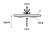
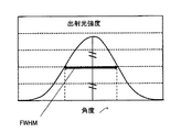
ここで、拡散角度及び出射光の出射方向の等方性/異方性について説明する。本発明において、拡散角度とは、図2に示すように、拡散部材13の凹凸構造が形成された主面に対して垂直方向に光が入射したときに出射する光の強度を測定し、角度と強度でプロットした曲線(図3)において、ピーク強度の半分に減衰する角(半値角)の2倍の角度(Full Width Half Maximum、以下、「FWHM」ともいう。)のことを示す。
Here, the isotropic / anisotropy of the diffusion angle and the outgoing direction of the outgoing light will be described. In the present invention, the diffusion angle is an angle measured by measuring the intensity of light emitted when light is incident in a direction perpendicular to the main surface on which the concavo-convex structure of the
拡散角度は、例えば、変角光度計(日本電色工業社製、GC 5000L)を用いて、拡散部材13の凹凸構造が形成された主面(以下、凹凸面とする)を入光面とし、凹凸構造が形成された主面(図2の点線参照)の法線方向における入射光に対する透過光強度の角度分布を測定することによって求められる。ここで、拡散部材13の法線方向とは、図2に示すように、拡散部材13の凹凸面に対して垂直の方向を指す。図2中、拡散部材13を透過する種々の方向の光のうち、凹凸面の法線方向から入射した光が、拡散部材13の凹凸面から鉛直方向(基準角度0度)へと透過する光の透過光強度が最も高い。この透過光強度が、最も高い透過光強度(ピーク強度)の半分になるときの角度(基準角度からの角度)の2倍の角度が、拡散角度(FWHM)である(図3参照)。
For the diffusion angle, for example, using a goniophotometer (manufactured by Nippon Denshoku Industries Co., Ltd., GC 5000L), the main surface on which the concavo-convex structure of the diffusing
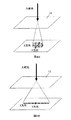
図4A、図4Bは、出射光の等方性/異方性の説明図である。本発明においては、図4Aに示すように、拡散部材13を透過して出光する出射光が、どの方向においても等しい拡散角度を示す場合は等方性拡散パタンとする(図4Aにおいては、X方向及びY方向における拡散角度が同じ)。一方、図4Bに示すように、拡散部材13を透過して出光する出射光が、方向によって拡散角度が異なる場合は異方性拡散とする(図4Bにおいては、X方向における拡散角度が、Y方向に対して大きい)。本実施の形態において、拡散部材13としては、等方性拡散パタン、異方性拡散パタンのいずれを示すものも使用可能である。
4A and 4B are explanatory diagrams of the isotropic / anisotropy of the emitted light. In the present invention, as shown in FIG. 4A, the isotropic diffusion pattern is used when the outgoing light transmitted through the diffusing
また、本実施の形態に係る拡散部材13において、拡散パタンが等方性拡散パタンである場合には、点Aにおける拡散角度a、及び点Bにおける拡散角度bに対して、拡散角度の差(a−b)が、拡散角度の平均値{(a+b)/2}の±10%の範囲内となる場合に点A及び点Bは、互いに拡散パタンが同じ領域に属するものとする。また、以上の条件を満たさない場合には、点A及び点Bは、互いに拡散パタンが異なる領域に属するものとする。
Further, in the diffusing
また、本実施の形態に係る拡散部材において、拡散パタンが異方性拡散パタンである場合には、点Aにおける拡散角度が最大となる方向の拡散角度amax、及び拡散角度が最小となる方向の拡散角度amin、並びに点Bにおける拡散角度が最大となる方向の拡散角度bmax、及び拡散角度が最小となる方向の拡散角度bminに対して、最大拡散角度の差(amax−bmax)が最大拡散角度の平均値{(amax+bmax)/2}の±10%の範囲内となり、かつ最小拡散角度の差(amin−bmin)が最小拡散角度の平均値{(amin+bmin)/2}の±10%の範囲内となり、かつ点A及び点Bにおける拡散角度が最大となる方向がなす角が5度以内である場合に点A及び点Bは、互いに拡散パタンが同じ領域に属するものとする。また、以上の条件の少なくとも1つを満たさない場合には、点A及び点Bは、互いに拡散パタンが異なる領域に属するものとする。以下においては、説明の便宜上、特に断らない限り、拡散パタンが等方性拡散パタンであるものとして説明する。 In the diffusion member according to the present embodiment, when the diffusion pattern is an anisotropic diffusion pattern, the diffusion angle amax in the direction in which the diffusion angle at the point A is the maximum and the direction in which the diffusion angle is the minimum The difference in maximum diffusion angle (amax−bmax) is the maximum diffusion angle with respect to the diffusion angle amin, the diffusion angle bmax in the direction in which the diffusion angle at the point B is maximum, and the diffusion angle bmin in the direction in which the diffusion angle is minimum. Is within the range of ± 10% of the average value {(amax + bmax) / 2}, and the difference of the minimum diffusion angle (amin−bmin) is within the range of ± 10% of the average value {(amin + bmin) / 2} of the minimum diffusion angle When the angle formed by the direction in which the diffusion angles at points A and B are the maximum is within 5 degrees, point A and point B belong to the same region where the diffusion patterns belong to each other. It shall be. Further, when at least one of the above conditions is not satisfied, the point A and the point B belong to regions having different diffusion patterns. In the following description, for the convenience of explanation, the diffusion pattern is assumed to be an isotropic diffusion pattern unless otherwise specified.
本実施の形態においては、拡散部材13の第1の領域A1及び第2の領域A2の拡散角度は、以下のような方法で求めることができる。第一に、例えば、縦方向(X方向)2mm、横方向(Y方向)2mmのピッチで拡散部材13の全面に渡って拡散角度を測定する(必要に応じて、部分的により細かいピッチで測定してもよい。)。第二に、上述した拡散パタンが同じ領域か異なる領域かの判断基準に従って、各測定点を第1の領域A1及び第2の領域A2に分ける。
In the present embodiment, the diffusion angles of the first region A1 and the second region A2 of the diffusing
例えば、縦方向(X方向)に測定した測定点の拡散角度が、順に50、47、50、53、50、10、11、9、10、49、51度であった場合、第1の領域A1の示す拡散角度を50±5度とし、第2の領域A2の示す拡散角度は10±1度とする。この場合、拡散角度が50の測定点と10の測定点との中間に第1の領域A1と第2の領域A2との境界線があり、拡散角度が10の測定点と49の測定点との中間に第2の領域A2と第1の領域A1との境界線があることになる。このようにして拡散部材13の全面に渡って境界線を引くことで拡散部材13の主面を第1の領域A1及び第2の領域A2に分割することができる。
For example, when the diffusion angles of the measurement points measured in the vertical direction (X direction) are 50, 47, 50, 53, 50, 10, 11, 9, 10, 49, 51 degrees in order, the first region The diffusion angle indicated by A1 is 50 ± 5 degrees, and the diffusion angle indicated by the second region A2 is 10 ± 1 degrees. In this case, there is a boundary line between the first region A1 and the second region A2 between the measurement point with the diffusion angle of 50 and the measurement point of 10, and the measurement point with the diffusion angle of 10 and 49 There is a boundary line between the second region A2 and the first region A1 in the middle. Thus, the main surface of the diffusing
領域の拡散角度とは、当該領域内における拡散角度の測定値の最大値と最小値との平均値をいうものとする。第1の領域A1及び第2の領域A2の拡散パタンの示す拡散角度としては、第1の領域A1及び第2の領域A2間における拡散角度の差が10度以上であることが好ましい。第1の領域A1及び第2の領域A2間における拡散角度の差が10度以上であれば、第1の領域A1が示す拡散パタンと第2の領域A2が示す拡散パタンとの差が大きくなるので、拡散部材を透過する透過光の光学特性の変化が大きくなり、グレアを抑制することができる。 The diffusion angle of a region means an average value of the maximum value and the minimum value of the measurement values of the diffusion angle in the region. As the diffusion angle indicated by the diffusion pattern of the first region A1 and the second region A2, the difference in diffusion angle between the first region A1 and the second region A2 is preferably 10 degrees or more. If the difference in diffusion angle between the first region A1 and the second region A2 is 10 degrees or more, the difference between the diffusion pattern indicated by the first region A1 and the diffusion pattern indicated by the second region A2 becomes large. Therefore, the change in the optical characteristics of the transmitted light that passes through the diffusing member becomes large, and glare can be suppressed.
本実施の形態に係る拡散部材13においては、互いに異なる拡散パタンを示す少なくとも1つの第1の領域A1と複数の第2の領域A2とが、拡散部材13の主面内において互いに隣接して設けられる。「第1の領域A1と第2の領域A2とが主面内で互いに隣接して配置されている」とは、拡散部材13の主面内を上述のように拡散角度の測定値によって複数の領域に分割したときに、第1の領域A1の境界線の少なくとも一部が、第2の領域A2との境界線であることを意味し、必ずしも第1の領域A1の境界線の全体が、第2の領域A2との境界線である必要はない。また、第1の領域A1が、第2の領域A2に隣接して配置されているとともに、第1の領域A1にも第2の領域A2にも属さない第3の領域A3と隣接して配置されていてもよい。さらに第1の領域A1が、第2の領域A2と第3の領域A3とに隣接して配置されているとともに、第1の領域A1にも第2の領域A2にも第3の領域A3にも属さない第4の領域A4と隣接して配置されていてもよい(図7参照)。
In the diffusing
拡散パタンが等方性拡散の拡散部材13については、前述の測定方法によって拡散角度を測定した結果を元に、例えば、60度や、60度×60度などのように表記し、拡散パタンが異方性拡散の拡散部材13については、拡散角度が最大となる方向、及びこの拡散角度が最大となる方向と直交する方向との二方向における拡散角度を測定し、例えば、60度×10度や、90度×30度などのように表記する(通常最大拡散角度を前に、最小拡散角度を後に記載する)。
For the
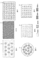
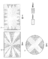
次に、図5A〜図5F及び図6A〜図6Cを参照して、本実施の形態に係る照明装置の拡散部材13における第1の領域A1及び第2の領域A2の配置の例について詳細に説明する。図5A〜図5F及び図6A〜図6Cは、本実施の形態に係る照明装置における拡散部材13の平面模式図であり、第1の領域A1及び第2の領域A2の配置例を示している。図5A〜図5F及び図6A〜図6Cにおいては、第1の領域A1は領域A1、第2の領域A2は領域A2とも記す。
Next, referring to FIGS. 5A to 5F and FIGS. 6A to 6C, an example of the arrangement of the first region A1 and the second region A2 in the diffusing
図5A〜図5Fに示す例においては、第1の領域A1は、拡散部材13の面内において連続して存在し、この第1の領域A1に囲まれるように複数の第2の領域A2が存在する。このように、第2の領域A2が拡散部材13の主面内において、閉じた線で区切られる際には、第1の領域A1は単数となり、この第1の領域A1に囲まれて複数の第2の領域A2が存在する。
In the example shown in FIGS. 5A to 5F, the first region A1 exists continuously in the plane of the diffusing
図6A〜図6Cに示す例においては、第2の領域A2が拡散部材13の主面内において、閉じた線で区切られない例について示している。この場合においては、複数の第1の領域A1及び複数の第2の領域A2を有する構成でもよく(図6A)、単数の第1の領域A1と、複数の第2の領域A2とを有する構成であってもよい(図6B、図6C)。なお、拡散部材13の形状としては、平面視にて略矩形形状(図5A〜図5C、図5E、図5F、図6A、及び図6B)であってもよく、円形形状(図5D及び図6C)であってもよく、拡散部材13が適用される照明装置によって、適宜選択することが可能である。
In the example shown in FIGS. 6A to 6C, an example is shown in which the second region A <b> 2 is not separated by a closed line in the main surface of the diffusing
本実施の形態に係る拡散部材13においては、拡散部材13の主面内に設けられる複数の第2の領域A2の形状が略同一形状であることが好ましく、第2の領域A2が規則的に配列されてなることがさらに好ましい。このように、略同一の拡散パタンを示す第2の領域A2を略同一形状に揃えることにより、拡散部材13の主面内における拡散角度の分布に規則性が生じるので、出射光の拡散角度が揃いグレアを効果的に低減することが可能となる。さらに、第2の領域A2を規則的に配列することにより、出射光の拡散角度がより揃うので、より効果的にグレアを低減することが可能となる。
In the diffusing
図5A、図5C〜図5F及び図6A〜図6Cにおいては、第1の領域A1及び第2の領域A2の拡散パタンが共に等方性拡散パタンである例について説明したが、図5Bに示すように、第1の領域A1及び第2の領域A2の拡散パタンは、共に異方性拡散パタンであってもよい。また、第1の領域A1及び第2の領域A2のいずれか一方の拡散パタンが等方性拡散パタンであり、他方の拡散パタンが異方性拡散パタンであってもよい。 5A, FIG. 5C to FIG. 5F, and FIG. 6A to FIG. 6C have described examples in which the diffusion patterns of the first region A1 and the second region A2 are both isotropic diffusion patterns. As described above, the diffusion patterns of the first region A1 and the second region A2 may both be anisotropic diffusion patterns. Further, either one of the first region A1 and the second region A2 may be an isotropic diffusion pattern, and the other diffusion pattern may be an anisotropic diffusion pattern.
第1の領域A1及び第2の領域A2のいずれもが異方性拡散パタンの場合は、次のような場合に分けられる。すなわち、第1の領域A1の異方性拡散パタンの拡散角度がa度×b度であり、第2の領域A2の異方性拡散パタンの拡散角度がc度×d度(a≠c、b≠d、a>b、c>d)である場合と、図5Bに示すように、第1の領域A1及び第2の領域A2の異方性拡散パタンがいずれもa度×b度であるが、最大の異方性を示す方向が異なる場合とがある。図5Bの第1の領域A1と第2の領域A2においては、斜線の方向で異方性の方向を模式的に示している。異方性拡散パタンの拡散角度は、第1の領域A1と第2の領域A2いずれもa度×b度であるが、異方性拡散を示す方向は、互いに90度異なっている。 When both of the first region A1 and the second region A2 are anisotropic diffusion patterns, they are classified into the following cases. That is, the diffusion angle of the anisotropic diffusion pattern in the first region A1 is a degree × b degrees, and the diffusion angle of the anisotropic diffusion pattern in the second region A2 is c degrees × d degrees (a ≠ c, In the case of b ≠ d, a> b, c> d), and as shown in FIG. 5B, the anisotropic diffusion patterns of the first region A1 and the second region A2 are both a degree × b degree. There are cases where the direction of maximum anisotropy is different. In the first region A1 and the second region A2 in FIG. 5B, the direction of anisotropy is schematically shown in the direction of the oblique lines. The diffusion angle of the anisotropic diffusion pattern is a degree × b degree in both the first region A1 and the second region A2, but the directions indicating anisotropic diffusion are different from each other by 90 degrees.
本実施の形態においては、拡散部材13において、第1の領域A1及び第2の領域A2の配列がランダムであってもよく、第1の領域A1及び第2の領域A2の形状がそれぞれ異なっていてもよい。製造の簡便性の点から、少なくとも第2の領域A2は、規則的に配列されていることが好ましい。第2の領域A2が規則的に配列されているとは、拡散部材13の主面の平面視における第2の領域A2の重心となる点の配置に、周期的な繰り返しとなる構造を有していることを意味する。製造が容易であるのは、複数の第2の領域A2が、直線上に等間隔に配列された構造(例えば図5A、図5B、図5C、図5E、図5F)や、同一円周上に等間隔に第2の領域が配列された構造(例えば図5D)などである。
In the present embodiment, in the diffusing
本実施の形態においては、拡散部材13の主面内における第2の領域A2の形状は円形、又は多角形であるか、曲線及び/又は直線からなる形状である。この第2の領域A2の形状や面積は用途や目的に応じて適宜選択することが可能であるが、製造の簡便性から、真円、楕円、多角形、星型等、図形自体に線対称性または点対称性を有する形状が好ましい。
In the present embodiment, the shape of the second region A2 in the main surface of the diffusing
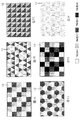
また、第1の領域A1及び第2の領域A2(第3の領域A3及び第4の領域A4)は、平面視にて略同一の形状を有する領域であり、面内を埋め尽くすことが可能な形状であることがパタン原型の製造上好ましい。同一の形状を有する領域で面内を埋め尽くすことが可能な領域とは、例えば、図7A〜図7Fに示すように、第1〜第4の領域A1〜A4の形状が、正方形(長方形)、正三角形、直角二等辺三角形、正六角形、およびこれらを点、辺で接続した単位図形である。 The first region A1 and the second region A2 (third region A3 and fourth region A4) are regions having substantially the same shape in plan view, and can fill the in-plane. It is preferable for the production of the pattern prototype to be a simple shape. For example, as shown in FIG. 7A to FIG. 7F, the region in which the in-plane can be filled with the region having the same shape is a square (rectangular) shape in the first to fourth regions A1 to A4. , Regular triangles, right-angled isosceles triangles, regular hexagons, and unit figures connected by points and sides.
図7A〜図7Fに示すように、同一の形状を有する第1〜第4の領域A1〜A4で拡散部材13の主面内を埋め尽くした場合、拡散パタンが2種類である場合は、必然的に第1〜第4の領域A1〜A4のうち、2種類の領域が繰り返し配列される構造となる(図7C、図7F)。領域が3種類以上である場合は、図7A、図7Dに示すように、第1の領域A1〜第3の領域A3の配列が規則的であってもよく、図7B、図7Eに示すように、各第1の領域A1〜第4の領域A4の配列が不規則であってもよい。
As shown in FIGS. 7A to 7F, when the main surface of the diffusing
本実施の形態に係る拡散部材13において、出射する光の拡散パタンを形成する凹凸構造は、拡散パタンと称する拡散角度と異方性とを制御する機能を有する。凹凸構造は、機械加工、レーザー切削、干渉露光法などにより、微細なレンズパタンや凹凸を形成したものを元型とする。このような加工方法は、工程が非常に複雑であり、元型は高価であるため、大面積の微細凹凸パタンを得ることは難しい。本実施の形態においては、小面積の微細凹凸パタンが形成できれば、それをいくつか組み合わせることにより、拡散部材全体の出光特性を自由に制御することが可能である。また、第1の領域A1及び第2の領域A2の形状が同一であれば、ある決まった種類の拡散パタンから、必要な出光特性を得るためのシミュレーションが簡便となり、実測値との差が少なくなる。
In the diffusing
本実施の形態において、拡散部材13は、第1の領域A1に凹凸構造が形成された面から垂直に光を入射したときに出射する光の拡散角度、及び第2の領域A2に凹凸構造が形成された面から垂直に光を入射したときに出光する光の拡散角度が、共に0.1度〜100度の範囲内であることが、製造上の点から好ましい。ある領域の拡散パタンが異方性拡散の場合、最小拡散角度と最大拡散角度がともにこの数値の範囲内となることが好ましい。
In the present embodiment, the diffusing
具体的には、拡散角度が0〜20度の第1の領域A1と、拡散角度が30〜50度の第2の領域A2と、の2領域からなる拡散部材、拡散角度が0〜5度の第1の領域A1と、拡散角度が6〜19度の第2の領域A2と、拡散角度が20〜40度の第3の領域A3と、の3領域からなる拡散部材、拡散角度が0〜9度の第1の領域A1と、拡散角度が10〜29度の第2の領域A2と、拡散角度が30〜50度の第3の領域A3と、の3領域からなる拡散部材、及び拡散角度が0〜19度の第1の領域A1と、拡散角度が20〜39度の第2の領域A2と、拡散角度が40〜60度の第3の領域A3と、の3領域からなる拡散部材を好ましく例示することができる。 Specifically, a diffusion member composed of two regions, a first region A1 having a diffusion angle of 0 to 20 degrees and a second region A2 having a diffusion angle of 30 to 50 degrees, and a diffusion angle of 0 to 5 degrees A diffusion member consisting of three regions, a first region A1, a second region A2 having a diffusion angle of 6 to 19 degrees, and a third region A3 having a diffusion angle of 20 to 40 degrees. A diffusion member composed of three regions: a first region A1 of ˜9 degrees, a second region A2 of a diffusion angle of 10 to 29 degrees, and a third region A3 of a diffusion angle of 30 to 50 degrees; It consists of three regions: a first region A1 having a diffusion angle of 0 to 19 degrees, a second region A2 having a diffusion angle of 20 to 39 degrees, and a third region A3 having a diffusion angle of 40 to 60 degrees. A diffusion member can be preferably exemplified.
また、本実施の形態に係る照明装置において、拡散部材13は、主面内の第1の領域A1及び第2の領域A2のうち、いずれか一方が拡散部材13の両主面共に平坦であることが好ましい。ここで、平坦とは、その第1の領域A1又は第2の領域A2で測定した拡散角度が0.1度未満であることを意味する。すなわち、拡散部材13の主面内に単数又は複数の第1の領域A1と複数の第2の領域A2とを含む少なくとも2種類以上の領域を設け、第1の領域A1と第2の領域A2とを主面内で互いに隣接して設ける。そして、第1の領域A1及び第2の領域A2のうちの一方を両主面ともに平坦とし、第1の領域A1及び第2領域A2のうちの他方の少なくとも一方の主面に拡散パタンを示す凹凸構造を形成する。これにより、第1の領域A1又は第2の領域A2の一方の領域において、入射する光を拡散することなく透過し、他方の領域に入射する光が凹凸構造によって拡散されて出光するので、グレアの発生を抑制しつつ、全光束の低下をさらに抑制することが可能となる。
Moreover, in the illuminating device according to the present embodiment, either one of the first area A1 and the second area A2 in the main surface of the
拡散部材13としては、拡散部材13を透過する出射光が異なる拡散パタンを示す領域を2種類以上設ける場合には、各領域における拡散パタンの拡散角度の差が10度以上であることが好ましい。各領域における拡散角度の差が10度より大きいと、複数の拡散パタンの組み合わせによる光学特性の変化が大きくなる。
When the
また、図5Bに示した例のように、拡散角度が同じa度×b度の異方拡散性を示すものを、第1の領域A1及び第2の領域A2毎に角度を変えて配置する場合は、最大角度を示す角度の方向の角度差が15度以上であることが好ましい。角度差が15度以上であることにより、異方性の方向を変えて生じる光学特性の変化が大きくなる。 In addition, as in the example shown in FIG. 5B, the ones having anisotropic diffusion characteristics with the same diffusion angle of a degree × b degrees are arranged at different angles for each of the first region A1 and the second region A2. In this case, the angle difference in the direction of the angle indicating the maximum angle is preferably 15 degrees or more. When the angle difference is 15 degrees or more, a change in optical characteristics caused by changing the direction of anisotropy becomes large.
なお、本実施の形態に係る拡散部材13において、凹凸構造は、少なくとも点光源12からの光が入光する入光面、光源からの光が出光する出光面のいずれか一方に形成されていればよく、入光面及び出光面の両面に形成されていてもよい。
In the diffusing
特に、凹凸構造が形成されている面が出光面となるように配置し、再帰反射によって、光源から斜め方向へ出光する光を正面方向へ立ち上げるとともに、光源の透過像をぼやかすようにすることが、グレア抑制の効果を得る観点から好ましい。 In particular, it is arranged so that the surface on which the concavo-convex structure is formed becomes the light exit surface, and the light that is emitted from the light source in an oblique direction is raised in the front direction by retroreflection, and the transmitted image of the light source is blurred. It is preferable from the viewpoint of obtaining the effect of suppressing glare.
拡散部材13の凹凸構造としては、表面に多数の突起部が設けられた構造であれば特に限定されず各種形状の凹凸構造を用いることが可能である。突起部の形状としては、例えば、略円錐状、略球状、略楕円体状、略レンチキュラーレンズ状、略放物面状のいずれでもよく、各突起部は、規則的に配列していても、不規則に配列していてもよい。また、凹凸構造を構成する各突起部間は、連続的な曲面でつながっていてもよい。さらに、不規則な凹凸が連続的な曲面でつながっている擬似ランダム構造も、好ましく用いることができる。
The concavo-convex structure of the diffusing
凹凸構造の形状は、サンドブラスト法による吹き付け量の調整や、拡散部材13の主面に樹脂ビーズを塗工して凹凸構造を形成する方法による塗工量の調整や、ビーズ径の調整などによって制御することができる。これらの方法によって、凹凸構造の形状を制御することで、所望の拡散角度を得ることが可能となる。これらの方法の中でも、特に、干渉露光によるスペックルパターンを用いて凹凸構造の形状を制御することにより、拡散角度の設定が容易となるので好ましい。また干渉露光によるスペックルパターンを用いて形成された3次元構造は、機械加工では困難であった凹凸のピッチが20μm以下の微細な凹凸構造とすることができる。
The shape of the concavo-convex structure is controlled by adjusting the spraying amount by the sand blast method, adjusting the coating amount by applying resin beads to the main surface of the
また、干渉露光によるスペックルパターンを用いて凹凸構造を形成する方法によれば、マイクロレンズのような等方性拡散を示す形状や、レンチキュラーレンズのような異方性拡散を示す形状の両方を容易に形成することができるため、拡散部材の凹凸構造の形成方法として好適な方法である。 Also, according to the method of forming a concavo-convex structure using a speckle pattern by interference exposure, both a shape showing isotropic diffusion like a microlens and a shape showing anisotropic diffusion like a lenticular lens are used. Since it can be formed easily, it is a suitable method for forming the concavo-convex structure of the diffusion member.
拡散部材13の入光面及び/又は出光面に設けられている凹凸構造の形状は、目的とする照射範囲の広さ及び形状に応じて任意に設計することができ、照射範囲の広さ及び形状を制御できる。
The shape of the concavo-convex structure provided on the light entrance surface and / or the light exit surface of the diffusing
拡散部材13の凹凸構造のピッチ及び高さとしては、人間の目の分解能以下、すなわち20μm以下とすると目立ちにくくなり、結果的に照明装置において美観を損ねないため好ましい。また、可視光の波長0.8μm以上であることが好ましい。
The pitch and height of the concavo-convex structure of the diffusing
また、凹凸構造としては、表面のぎらつき感や照明装置出光面における輝度の視野角依存性を抑制するという観点から、連続曲面により形成されている不規則な凹凸構造であることが好ましい。連続的曲面から形成されている不規則な微細凹凸構造は、次のようにして製造することができる。 In addition, the uneven structure is preferably an irregular uneven structure formed by a continuous curved surface from the viewpoint of suppressing the glare on the surface and the viewing angle dependency of luminance on the light emitting surface of the lighting device. The irregular fine concavo-convex structure formed from a continuous curved surface can be manufactured as follows.
まず、予め干渉露光により、レーザー光をレンズ、拡散板、アパーチャ、マスク等を介して感光性材料やフォトレジストに照射し、スペックルパターンを形成させた均一な拡散パタン領域となる凹凸の元型を作製する。レーザー照射システムを構成する部材間の距離やサイズを変えてスペックルパターンの寸法、形状及び方向を調節することにより、所望の凹凸構造、すなわち光の拡散パタンを得ることが出来る。 First, the original pattern of unevenness that becomes a uniform diffusion pattern area in which a speckle pattern is formed by previously irradiating a photosensitive material or photoresist with laser light through a lens, a diffuser plate, an aperture, a mask, etc. by interference exposure. Is made. A desired concavo-convex structure, that is, a light diffusion pattern, can be obtained by adjusting the size, shape and direction of the speckle pattern by changing the distance and size between the members constituting the laser irradiation system.
一般に、拡散部材を透過した光の拡散角度は、スペックルパターンの平均サイズ及び形状に依存する。スペックルパターンの高さが高く、ピッチが狭く、すなわちアスペクト比が高いほど、拡散角度が大きくなる。スペックルパターンのサイズは、例えば、SEM(走査型電子顕微鏡)や、超深度顕微鏡によって測定することができる。 In general, the diffusion angle of light transmitted through the diffusion member depends on the average size and shape of the speckle pattern. The higher the speckle pattern height and the narrower the pitch, that is, the higher the aspect ratio, the larger the diffusion angle. The size of the speckle pattern can be measured by, for example, an SEM (scanning electron microscope) or an ultra-deep microscope.
また、拡散部材13の凹凸構造を構成する単位構造は、等方性のものに限らず異方性のものを形成することもでき、等方性と異方性とが複合された凹凸構造とすることもできる。スペックルパターンが横方向を長軸とする楕円形であれば異方拡散性となり、縦方向の拡散角度が高くなる。この等方性又は異方性の調整は、拡散板、アパーチャのサイズや形状を変えることによって形成可能である。
Further, the unit structure constituting the concavo-convex structure of the diffusing
上記方法により、数種類の拡散パタンの凹凸元型を得た後、これを所定形状に配列して、本実施の形態に係る拡散部材13のサブマスタを得る。このサブマスタに対して、電鋳等の方法により金属を被着し、スペックルパターンの転写された金属製のマスタ型を製造する。
After obtaining the concave / convex original molds of several types of diffusion patterns by the above method, they are arranged in a predetermined shape to obtain the submaster of the
この金属製のマスタ型は平板であってもよいし、平板を円筒型に成形したロールでもよい。ロールとする場合、通常の拡散部材ではマスタの継目が発生し、この継目によってシートの生産性や品質が低下していたが、本実施の形態に係る拡散部材13では、マスタの継目があっても境界線をマスタの継目と合わせられる形状を有する領域とすることで、継目を目立ちにくくすることができる。また継目があっても、それにより光学的特性が低下することがない。
The metal master mold may be a flat plate or a roll obtained by forming the flat plate into a cylindrical shape. In the case of a roll, a master seam is generated in a normal diffusing member, and the productivity and quality of the sheet are reduced by this seam. However, in the diffusing
次に、光透過性を有する基材シート上に感光性樹脂を塗工し、マスタ型を用いて紫外線照射を行うことによって、スペックルパターンによる凹凸構造を転写して形成する。 Next, a photosensitive resin is applied on a light-transmitting substrate sheet, and ultraviolet light is irradiated using a master mold to transfer and form a concavo-convex structure with a speckle pattern.
紫外線は光透過性を有する基材シート裏面から照射し、これにより基材シートとマスタ型との境界面に凹凸構造が転写された硬化した感光性樹脂層が形成される。 Ultraviolet rays are irradiated from the back surface of the base material sheet having light permeability, thereby forming a cured photosensitive resin layer having a concavo-convex structure transferred to the boundary surface between the base material sheet and the master mold.
光透過性を有する基材シートとしては、紫外線を透過する材料を用いることができ、例えばガラス板、またはポリエステル、ポリカーボネート、トリアセチルセルロースなどの樹脂シートが好ましく用いられる。 As the base sheet having light transmittance, a material that transmits ultraviolet rays can be used. For example, a glass sheet or a resin sheet of polyester, polycarbonate, triacetyl cellulose, or the like is preferably used.
なお、拡散部材13の拡散角度は、凹凸構造のピッチ、高さ、アスペクト比を変えることによって制御できるが、紫外線によって硬化される感光性樹脂層の屈折率を変えることによっても制御できる。
The diffusion angle of the diffusing
上述のようにして凹凸構造を形成した基材シートを得た後、この基材シートを、光透過性材料からなり、かつ支持性を有する所定の基板に、所定の粘着材や熱を用いることにより、貼り合わせて拡散部材としてもよい。 After obtaining the base sheet having the concavo-convex structure as described above, the base sheet is made of a light-transmitting material and a predetermined adhesive material or heat is used for a predetermined substrate having supportability. Thus, the diffusion member may be bonded together.
上記基板としては、例えば、ガラス、ポリエチレンテレフタレート、ポリメチルメタクリレートやポリカーボネートなど、JIS K7361−1に定める全光線透過率が70%以上の透光性材料であれば好ましく用いることができる。 As the substrate, for example, a translucent material having a total light transmittance of 70% or more as defined in JIS K7361-1, such as glass, polyethylene terephthalate, polymethyl methacrylate, and polycarbonate can be preferably used.
また、拡散部材13は、上述したマスタ型を所定の成形機内に配置し、この成形機を用いて、ポリメチルメタクリレート、ポリカーボネート、ポリスチレン、シクロオレフィンポリマー等の透明樹脂による射出成形を行うことによっても製造できる。この射出成形法によれば、基板との貼り合わせ工程を要さず、凹凸構造の転写率が高く、成形品の強度も高いため、照明用途として好ましく用いられる。
The diffusing
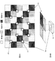
図8は、拡散部材13の第1〜第3の領域A1〜A3と点光源12との位置関係の一例を示す模式図である。なお、図8Aにおいては、拡散部材13の平面視における拡散部材13と、点光源12の発光部14及び投影範囲15と、の位置関係を示し、図8Bにおいては、図8Aに示した拡散部材13の一部の模式的な斜視図を示している。図8A、図8Bに示すように、本実施の形態に係る照明装置においては、拡散部材13の出光面を正面から見た際に、全点光源12の少なくとも半数の発光部14の投影範囲15内に、第1の領域A1、第2の領域A2、及び第3の領域A3のうちの少なくとも2つの領域が含まれることが好ましい。この構成により、拡散パタンが同一となる少なくとも2つの領域の複数面が、それぞれ同じ輝度で発光するように見えるので、1つの光源が複数個存在するように見えるため、グレアが抑制される。投影範囲15内に、第1の領域A1、第2の領域A2、及び第3の領域A3の3つの領域が含まれる場合は、拡散パタンが同一となる当該3つの領域の複数面が、それぞれ同じ輝度で発光するように見えるので、より好ましい。
FIG. 8 is a schematic diagram illustrating an example of the positional relationship between the first to third regions A1 to A3 of the diffusing
図5Dのような拡散部材13の形状であっても、点光源12の発光部14の投影範囲15内に第1の領域A1の少なくとも一部と第2の領域A2の少なくとも一部とが含まれるように点光源12が配置される場合、グレア抑制効果が発揮される。全ての点光源12がこのように配置されることが好ましいが、このように配置されない点光源12があっても全体の半数未満であれば、見る角度によって、点光源12の投影範囲15に、第1の領域A1の少なくとも一部と第2の領域A2の少なくとも一部とが含まれるように見えるため、グレア抑制は達成可能である。
Even in the shape of the diffusing
また、本実施の形態に係る照明装置においては、複数の第1の領域A1、及び複数の第2の領域A2のうち、少なくとも点光源12の発光部14の投影領域と重畳する全ての領域の面積が、それぞれ点光源12の発光部の投影領域の面積よりも小さいことが好ましい。このように、点光源12と拡散部材13の相対位置関係をあわせることにより、グレアを更に抑制することができる。
Moreover, in the illuminating device which concerns on this Embodiment, at least all the area | regions which overlap with the projection area | region of the
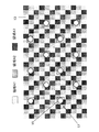
本実施の形態に係る照明装置においては、複数の第1の領域A1及び第2の領域A2のうち、全ての第1の領域A1及び第2の領域A2の面積が、それぞれ点光源12の発光部の投影範囲15の面積よりも小さいことが好ましい。この構成により、図9に示すように、点光源12と拡散部材13との相対的な位置関係によらずに、常に点光源12の発光部の投影範囲15に第1の領域A1の少なくとも一部と、第2の領域A2の少なくとも一部と、が含まれることになるため、グレア抑制効果を奏するために拡散部材13と点光源12との相対的な位置あわせを行う必要がなくなる。
In the lighting device according to the present embodiment, the area of all the first regions A1 and second regions A2 among the plurality of first regions A1 and second regions A2 is the light emission of the point
本実施の形態に係る拡散部材13は、シート状に形成して片面に粘着剤層を積層した拡散シートとして、窓貼り用の目隠しフィルムとして用いることが可能である。この場合、拡散部材13表面の凹凸構造は、必ずしも全面に形成されていなくてもよい。即ち、領域のうちで、凹凸が無く平坦となる領域が存在してもよい。平坦となる領域が存在することにより、その部分を通して屋内から外を見ることができ、光を拡散させるパタンの部分で、外からの目隠しが可能である。また、光透過率が、拡散剤を混合したシートよりも高いため、屋内の明るさを損なうことが無い。
The
以上説明したように、上記実施の形態に係る拡散部材においては、第1の領域A1及び/又は及び第2の領域A2に設けられた凹凸構造によって、第1の領域A1及び第2の領域A2が互いに異なる拡散パタンを示すので、拡散部材13の入光面側から入射した入射光が、第1の領域A1及び第2の領域A2によってそれぞれ異なる拡散角度で分散されて出光面側から出光する。これにより、拡散部材13内における点光源12近傍の領域の輝度を低減できるので、輝度の高い点光源を用いた照明装置においてもグレアの発生を抑制することが可能となる。また、第1の領域A1及び第2の領域A2の拡散パタンの差によってグレアを抑制するので、全光束の低下を抑制することが可能となる。
As described above, in the diffusing member according to the above embodiment, the first region A1 and the second region A2 are formed by the uneven structure provided in the first region A1 and / or the second region A2. Indicate different diffusion patterns, the incident light incident from the light incident surface side of the diffusing
特に、上記実施の形態に係る拡散部材においては、第1の領域A1及び第2の領域A2に設けた凹凸構造により、拡散部材13の主面内の光の透過性を低減することなく光を拡散してグレアの発生を抑制できるので、光の利用効率を高くすることができ、透過光の全光束低下を効果的に抑制できる。このため、従来公知の内部に拡散剤を含有する拡散板や、部分的に透過性を低減させた拡散部材を用いる場合と比較し、光源から入射して拡散板を透過して出光する光の全光束の低下を抑制することが可能となる。
In particular, in the diffusing member according to the above embodiment, the uneven structure provided in the first region A1 and the second region A2 allows light to be transmitted without reducing the light transmittance within the main surface of the diffusing
また、上記実施の形態に係る拡散部材においては、拡散部材13の主面内の所望の領域に互いに異なる第1及び第2の領域を設けることで、拡散部材13の主面内における透過性を低減させることなく、グレアの発生を抑制できるので、例えば、拡散部材13に対する照明装置の遊び、拡散部材13に撓みなどによる変形が生じた場合においても、グレアの発生を抑制することができる。このため、従来の照明装置と比較して、光源と拡散部材13との相対的な位置ズレが生じた場合においても、グレアの発生を抑制する効果が損なわれない。
In the diffusing member according to the above embodiment, by providing different first and second regions in a desired region in the main surface of the diffusing
以下、本発明の効果を明確にするために行った実施例、及び比較例について詳細に説明する。なお、本発明は、以下の実施例及び比較例によって何ら限定されるものではない。 Hereinafter, examples and comparative examples performed for clarifying the effects of the present invention will be described in detail. In addition, this invention is not limited at all by the following examples and comparative examples.
〔拡散部材〕
スペックルパターンを制御して、種々の凹凸構造が表面に形成されたマスタ型を作製した。予め干渉露光により、レーザー光をレンズ、拡散板、アパーチャ、マスクを介してフォトレジストに照射し、スペックルパターンを形成させた拡散パタンの元型を作成した。拡散板とアパーチャのサイズを変えて、出射する光の拡散パタンの異なる凹凸形状の元型を数種類作成し、これを、以下に述べる実施例における各拡散部材の各領域の形状として配列したマスタを作成した。次に、このマスタ型を用い、厚さ250μmのポリエチレンテレフタレート樹脂フィルム上に、紫外線硬化性樹脂からなる凹凸構造を賦形して拡散部材を作製した。
(Diffusion member)
By controlling the speckle pattern, a master mold having various uneven structures formed on the surface was produced. A prototype of a diffusion pattern in which a speckle pattern was formed by previously irradiating a photoresist with a laser beam through a lens, a diffusion plate, an aperture, and a mask by interference exposure. By changing the size of the diffuser and the aperture, several types of concave and convex masters with different diffusion patterns of emitted light were created, and masters arranged as the shapes of the respective regions of the respective diffusing members in the embodiments described below were prepared. Created. Next, using this master mold, an uneven structure made of an ultraviolet curable resin was formed on a polyethylene terephthalate resin film having a thickness of 250 μm to produce a diffusion member.
〔拡散部材の拡散角度〕
上記のようにして作製した拡散部材の凹凸構造が形成された面を照明装置の出光面とした。拡散部材の凹凸構造が形成された面の法線方向に入射した光に対する透過光強度の角度分布を変角光度計(GC 5000L、日本電色工業社製)で測定し、拡散部材の拡散角度を得た。
[Diffusion angle of diffusion member]
The surface on which the concavo-convex structure of the diffusion member produced as described above was formed was used as the light exit surface of the lighting device. The angle distribution of the transmitted light intensity with respect to the light incident in the normal direction of the surface of the diffusion member with the concavo-convex structure is measured with a goniophotometer (GC 5000L, manufactured by Nippon Denshoku Industries Co., Ltd.), and the diffusion angle of the diffusion member Got.
実施例1から実施例5、及び比較例1から比較例6については、以下に記載する照明装置を用いて評価した。 Example 1 to Example 5 and Comparative Example 1 to Comparative Example 6 were evaluated using the lighting devices described below.
〔照明装置〕
アルミダイキャスト製の基板面に白色ポリエステル樹脂製の反射シート(古河電工社製、MCPET(登録商標))を貼り、基板面の周縁部には、反射シートによる高さ10mmの壁面を形成して、図1Aに示す構成の照明装置を作製した。
[Lighting device]
A white polyester resin reflective sheet (Furukawa Electric Co., Ltd., MCPET (registered trademark)) is pasted on the aluminum die-cast substrate surface, and a 10 mm high wall is formed on the periphery of the substrate surface by the reflective sheet. A lighting device having the configuration shown in FIG. 1A was produced.
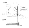
点光源12として、図10に示すように、縦横5mm、高さ1mmの寸法で、4mmφの発光部を有するような1WのLED光源を、基板面に45mmピッチで縦8個、横8個の正方格子状に計64個並べて配置した。
As the point
さらに、図11に示すように、基板面から所定の距離hを離して、後述する拡散部材を配置した構成とし、全体として、約360mm×360mmの照明装置とした。 Furthermore, as shown in FIG. 11, a diffusing member, which will be described later, is arranged at a predetermined distance h from the substrate surface, and the overall illumination device is approximately 360 mm × 360 mm.
〔配光測定〕
(1/2ビーム角)
配光測定は、照度計(ルクスハイテスタ、日置電機社製)を用いて実施した。
照明装置の出光面の法線方向と、照明装置の出光面から出射する光線の方向とのなす角度の絶対値は、以下のように、照明装置の出光面の中心位置を基準として照明装置を回転させて設定した。
[Light distribution measurement]
(1/2 beam angle)
The light distribution measurement was performed using an illuminometer (Lux Hitester, manufactured by Hioki Electric Co., Ltd.).
The absolute value of the angle formed between the normal direction of the light emitting surface of the lighting device and the direction of the light beam emitted from the light emitting surface of the lighting device is as follows with respect to the center position of the light emitting surface of the lighting device. Set by rotating.
具体的には、照度計を測定する照明装置の出光面の中心位置を基準として水平距離d=4000mm離して配置し、照明装置を水平方向に5度毎に回転させながら、出光面の鉛直方向を0度とした水平方向への回転角γが−90度〜90度の範囲で測定した照度値E(lx)と、水平距離d(m)と、から下記(式1)によって光度I(cd)に換算して照明装置の配光特性を得た。
I=E・d2 ・・・(式1)
ここで、照明装置の出光面の法線方向と、光度が法線方向における光度の1/2となる方向とのなす角度の絶対値の2倍の角度を、1/2ビーム角とした。
Specifically, the horizontal position d is set to be 4000 mm apart from the center position of the light exit surface of the illumination device that measures the illuminometer, and the illumination device is rotated every 5 degrees in the horizontal direction while the vertical direction of the light exit surface. From the illuminance value E (lx) measured in the range of the horizontal rotation angle γ from −90 ° to 90 ° with the horizontal angle d (m) as 0 °, the luminous intensity I ( The light distribution characteristic of the lighting device was obtained in terms of cd).
I = E · d 2 (Formula 1)
Here, an angle that is twice the absolute value of the angle formed between the normal direction of the light exit surface of the illuminating device and the direction in which the luminous intensity is ½ of the luminous intensity in the normal direction is defined as a ½ beam angle.
1/2ビーム角は、照明器具の出光面の法線方向における光度値が1/2となる角度を、光源を1度毎に回転させながら測定した。 The 1/2 beam angle was measured while rotating the light source every 1 degree so that the luminous intensity value in the normal direction of the light exit surface of the lighting fixture becomes 1/2.
この場合、配光特性と1/2ビーム角の測定を行う際、照明装置の出光面形状は、正方形であるため、正方形の中心を通る線分であって4辺のいずれかに平行な線分を回転軸として測定した。 In this case, when the light distribution characteristic and the 1/2 beam angle are measured, the shape of the light exit surface of the illuminating device is a square, and therefore a line segment passing through the center of the square and parallel to any of the four sides. Minutes were measured as the axis of rotation.
〔配光測定〕
(60度光度)
配光測定の結果より、照明装置の発光面の鉛直方向を0度とした場合において、斜め60度方向への光度を斜めグレアの評価基準の一つとした。LED光源のみで拡散パネルなどが存在しない場合の60度方向の光度を100とした場合の相対値として、それぞれの光学シートの60度方向の光度を算出して比較した。なお、オフィスなどで用いられる天井照明においては、斜め60度より広角方向への出光量を抑えることが好ましいとされている。
[Light distribution measurement]
(60 degree luminous intensity)
From the result of the light distribution measurement, when the vertical direction of the light emitting surface of the lighting device is 0 degree, the light intensity in the oblique 60 degree direction is set as one of the evaluation criteria of the oblique glare. As a relative value when the luminous intensity in the direction of 60 degrees when the diffusion panel or the like does not exist only with the LED light source is set to 100, the luminous intensity in the direction of 60 degrees of each optical sheet was calculated and compared. In ceiling lighting used in offices and the like, it is preferable to reduce the amount of light emitted in the wide-angle direction from 60 degrees obliquely.
(全光束)積分球による測定
全光束は、積分球型全光束測定システムを用いて測定した。積分球としては、1000mmφ積分全球(Labsphere社製、CSLMS LED 4061)を用い、照明器具を積分球の中心に出光面を受光ファイバーと反対方向を向けた状態で配置して測定した。なお、全光束の測定値は、後述する比較例3(LED光源のみで、拡散パネルなどが存在しない場合)の測定値を100とする相対値で表した。
(Total luminous flux) Measurement with integrating sphere Total luminous flux was measured using an integrating sphere type total luminous flux measurement system. As the integrating sphere, a 1000 mmφ integrating whole sphere (manufactured by Labsphere, CSLMS LED 4061) was used, and the measurement was performed with the illuminating device placed at the center of the integrating sphere with the light exit surface facing away from the receiving optical fiber. In addition, the measured value of the total luminous flux was expressed as a relative value with the measured value of Comparative Example 3 (in the case where only the LED light source is used and no diffusing panel or the like is present) as 100.
〔グレア評価〕
グレアは、上記配光測定と同じように、照明装置を回転させながら、評価した。
正面グレアは照明装置の出光面の鉛直方向(0度)で4000mmの距離から照明装置を直視し、斜めグレアは出光面の斜め方向(方位角30度〜60度の範囲)で4000mmの距離から照明装置を直視し、目視により評価した。
○ : 不快ではない (直視に耐える、LEDの輝点がぼやけている/複数に見える)
△ : やや不快である(LEDの輝点がややぼやけている)
× : 不快である (LEDの輝点が目立ち、直視に耐えない)
[Glare evaluation]
Glare was evaluated while rotating the illumination device in the same manner as the light distribution measurement.
The front glare looks directly at the lighting device from a distance of 4000 mm in the vertical direction (0 degree) of the light emitting surface of the lighting device, and the oblique glare looks from a distance of 4000 mm in the diagonal direction of the light emitting surface (azimuth angle of 30 to 60 degrees). The lighting device was directly viewed and evaluated visually.
○: Not uncomfortable (withstands direct viewing, LED bright spots are blurred / appear to be multiple)
Δ: Slightly uncomfortable (LED bright spots are slightly blurred)
×: Uncomfortable (LED bright spots are conspicuous and cannot withstand direct viewing)
〔総合判定〕
全光束、60度方向の光度、正面グレア及び斜めグレアの評価結果におけるマイナス判定要素を設定し、下記基準によるマイナス判定要素の数を指標として、総合的に判定した。
(マイナス判定要素)
全光束(相対値): 95未満
60度方向の光度: 75以上
グレア評価 : ×(2要素相当)、△(1要素相当)
(判定基準)
A判定 : マイナス判定要素なし。
B判定 : マイナス判定要素が1つ。
C判定 : マイナス判定要素が2つ以上。
〔Comprehensive judgment〕
Negative determination elements in the evaluation results of the total luminous flux, the luminous intensity in the direction of 60 degrees, the front glare, and the oblique glare were set, and comprehensive determination was performed using the number of negative determination elements according to the following criteria as an index.
(Negative judgment element)
Total luminous flux (relative value): less than 95
Luminous intensity in the direction of 60 degrees: 75 or more
Glare evaluation: × (equivalent to 2 elements), △ (equivalent to 1 element)
(Criteria)
A determination: No negative determination element.
B determination: One negative determination element.
C determination: Two or more negative determination elements.
〔実施例1〕
実施例1の照明装置においては、拡散角度の水準を2種類有し、図5Eのように拡散角度の異なる領域が規則的に配置しているような拡散部材を用いた。
[Example 1]
In the illuminating device of Example 1, a diffusion member having two types of diffusion angle levels and regularly arranging regions having different diffusion angles as shown in FIG. 5E was used.
拡散角度の水準は、10度、40度とし、拡散角度10度の第1の領域A1に、2mm角の拡散角度40度の複数の第2の領域A2がピッチ4mmで縦90個×横90個分布しているような拡散部材を作製し、照明装置に配置した。実施例1の全光束、60度方向の光度及びグレアの評価結果を下記表1に示した。 The level of the diffusion angle is 10 degrees and 40 degrees, and a plurality of second areas A2 having a diffusion angle of 40 degrees of 2 mm square are 90 mm long by 90 mm wide at a pitch of 4 mm in the first area A1 having a diffusion angle of 10 degrees. Diffusion members that are distributed individually were produced and placed in a lighting device. The evaluation results of the total luminous flux, the luminous intensity in the direction of 60 degrees, and the glare of Example 1 are shown in Table 1 below.
本実施例においては、拡散部材を具備しない場合と比較して、全光束低下を4%程度に抑制しつつ、光源の擬似多灯化によって正面グレア及び斜めグレアを抑制することができ、照明装置として実用上良好な特性を有していることが分かった。 In this embodiment, compared with the case where no diffusing member is provided, the front glare and the oblique glare can be suppressed by the pseudo multiple lighting of the light source while suppressing the decrease in the total luminous flux to about 4%. As a result, it was found that it has practically good characteristics.
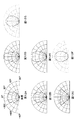
本実施例においては、異なる2つの拡散角度の水準をベースとし、図12Aに示すように、2つの拡散角度の中間の拡散角度となるような拡散部材の配光特性を再現するとともに、グレア抑制効果を向上させることができた。 In this embodiment, based on two different diffusion angle levels, as shown in FIG. 12A, the light distribution characteristics of the diffusing member that is an intermediate diffusion angle between the two diffusion angles are reproduced, and glare suppression is achieved. The effect could be improved.
〔実施例2〕
実施例2の照明装置においては、拡散角度の水準を2種類有し、図5Fのように拡散角度の異なる領域が規則的に配置しているような拡散部材を用いた。
[Example 2]
In the illuminating device of Example 2, a diffusion member having two types of diffusion angle levels and regularly arranging regions having different diffusion angles as shown in FIG. 5F was used.
拡散角度の水準は、10度、40度とし、拡散角度10度の第1の領域A1に、3mm角の拡散角度40度の複数の第2の領域A2がピッチ4mmで縦90個×横90個分布しているような拡散部材を作製し、照明装置に配置した。実施例2の全光束、60度方向の光度及びグレアの評価結果を下記表1に示した。 The diffusion angle levels are 10 degrees and 40 degrees, and a plurality of second areas A2 having a diffusion angle of 40 degrees of 3 mm square and 90 mm length × width 90 degrees in a pitch of 4 mm in the first area A1 having a diffusion angle of 10 degrees. Diffusion members that are distributed individually were produced and placed in a lighting device. The evaluation results of the total luminous flux, the luminous intensity in the direction of 60 degrees, and the glare of Example 2 are shown in Table 1 below.
本実施例においては、拡散部材を具備しない場合と比較して、全光束低下を4%程度に抑制しつつ、光源の擬似多灯化によって正面グレア及び斜めグレアを抑制することができ、照明装置として実用上良好な特性を有していることが分かった。 In this embodiment, compared with the case where no diffusing member is provided, the front glare and the oblique glare can be suppressed by the pseudo multiple lighting of the light source while suppressing the decrease in the total luminous flux to about 4%. As a result, it was found that it has practically good characteristics.
本実施例においては、異なる2つの拡散角度の水準をベースとし、図12Bに示すように、2つの拡散角度の中間の拡散角度となるような拡散部材の配光特性を再現するとともに、グレア抑制効果を向上させることができた。 In this embodiment, based on two different diffusion angle levels, as shown in FIG. 12B, the light distribution characteristics of the diffusing member such that the diffusion angle is intermediate between the two diffusion angles are reproduced, and the glare is suppressed. The effect could be improved.
〔実施例3〕
実施例3の照明装置においては、拡散角度の水準を3種類有し、図7Aのように拡散角度の異なる各領域の形状が5mm角の正方形状であるような拡散部材を用いた。
Example 3
In the illuminating device of Example 3, a diffusion member having three levels of diffusion angles and having a square shape of 5 mm square in each region having a different diffusion angle as shown in FIG. 7A was used.
拡散角度の水準は、拡散角度1度の第1の領域A1、拡散角度11度の第2の領域A2、拡散角度30度の第3の領域A3とし、すべてのLED光源の発光部の投影範囲内に第1の領域A1と第2の領域A2と第3の領域A3のうちの少なくとも2つの領域が含まれるように照明装置に配置した。実施例3の全光束、60度方向の光度及びグレアの評価結果を下記表1に示した。 The diffusion angle levels are a first area A1 with a diffusion angle of 1 degree, a second area A2 with a diffusion angle of 11 degrees, and a third area A3 with a diffusion angle of 30 degrees, and the projection ranges of the light emitting portions of all LED light sources. It arrange | positioned in the illuminating device so that at least 2 area | region of 1st area | region A1, 2nd area | region A2, and 3rd area | region A3 might be included in it. The evaluation results of the total luminous flux, the luminous intensity in the direction of 60 degrees, and the glare of Example 3 are shown in Table 1 below.
本実施例においては、拡散部材を具備しない場合と比較して、全光束低下を4%程度に抑制しつつ、光源の擬似多灯化によって正面グレア及び斜めグレアを抑制することができ、照明装置として実用上良好な特性を有していることが分かった。 In this embodiment, compared with the case where no diffusing member is provided, the front glare and the oblique glare can be suppressed by the pseudo multiple lighting of the light source while suppressing the decrease in the total luminous flux to about 4%. As a result, it was found that it has practically good characteristics.
本実施例においては、図12Cに示すように、拡散角度が主面内で一様なものと比較し、広角30度方向〜45度方向への出光成分が多く、広い面を均一に照射することが可能なため、天井面に用いる照明装置として好ましい形態を実現することができた。すなわち、主面内の拡散角度が一様な拡散部材では実現できないような配光特性が得られた。 In the present embodiment, as shown in FIG. 12C, compared with the case where the diffusion angle is uniform in the main surface, there are more light emission components in the wide angle direction of 30 ° to 45 °, and the wide surface is uniformly irradiated. Therefore, a preferable form as a lighting device used for the ceiling surface could be realized. That is, a light distribution characteristic that cannot be realized by a diffusion member having a uniform diffusion angle in the main surface was obtained.
〔実施例4〕
実施例4の照明装置においては、拡散角度の水準を3種類有し、図7Aのように各拡散角度の異なる領域の形状が5mm角の正方形状であるような拡散機材を用いた。
Example 4
In the illuminating device of Example 4, diffusion equipment having three types of diffusion angle levels and having a square shape of 5 mm square in each region having different diffusion angles as shown in FIG. 7A was used.
拡散角度の水準は、拡散角度4度の第1の領域A1、拡散角度20度の第2の領域A2、拡散角度42度の第3の領域A3とし、すべてのLED光源の発光部の投影範囲内に第1の領域A1と第2の領域A2と第3の領域A3のうちの少なくとも2つの領域が含まれるように照明装置に配置した。実施例4の全光束、60度方向の光度及びグレアの評価結果を下記表1に示した。 The diffusion angle levels are a first area A1 with a diffusion angle of 4 degrees, a second area A2 with a diffusion angle of 20 degrees, and a third area A3 with a diffusion angle of 42 degrees, and the projection ranges of the light emitting portions of all LED light sources. It arrange | positioned in the illuminating device so that at least 2 area | region of 1st area | region A1, 2nd area | region A2, and 3rd area | region A3 might be included in it. The evaluation results of the total luminous flux, the luminous intensity in the direction of 60 degrees, and the glare of Example 4 are shown in Table 1 below.
本実施例においては、拡散部材を具備しない場合と比較して、全光束低下を4%程度に抑制しつつ、光源の擬似多灯化によって正面グレア及び斜めグレアを抑制することができ、照明装置として実用上良好な特性を有していることが分かった。 In this embodiment, compared with the case where no diffusing member is provided, the front glare and the oblique glare can be suppressed by the pseudo multiple lighting of the light source while suppressing the decrease in the total luminous flux to about 4%. As a result, it was found that it has practically good characteristics.
本実施例においては、図12Dに示すように、拡散角度が主面内で一様なものと比較し、5度方向への出光成分を0度方向の出光成分より多くすることにより、照明装置直下方向のある範囲を選択的に照射することが可能となった。すなわち、主面内の拡散角度が一様な拡散部材では実現できないような配光特性が得られた。 In this embodiment, as shown in FIG. 12D, the illumination device is configured such that the light emission component in the direction of 5 degrees is larger than the light emission component in the direction of 0 degrees as compared with the diffusion angle uniform in the main surface. It became possible to selectively irradiate a certain range in the direct downward direction. That is, a light distribution characteristic that cannot be realized by a diffusion member having a uniform diffusion angle in the main surface was obtained.
〔実施例5〕
実施例5の照明装置においては、拡散角度の水準を3種類有し、図7Aのように各拡散角度の異なる領域の形状が5mm角の正方形状であるような拡散部材を用いた。
Example 5
In the illuminating device of Example 5, a diffusion member having three types of diffusion angle levels and having a square shape of 5 mm square in each of the regions having different diffusion angles as shown in FIG. 7A was used.
拡散角度の水準は、拡散角度11度の第1の領域A1、拡散角度29度の第2の領域A2、拡散角度41度の第3の領域A3とし、すべてのLED光源の発光部の投影範囲内に第1の領域A1と第2の領域2と第3の領域A3のうちの少なくとも2つの領域が含まれるように照明装置に配置した。実施例5の全光束、60度方向の光度及びグレアの評価結果を下記表1に示した。 The diffusion angle levels are a first area A1 with a diffusion angle of 11 degrees, a second area A2 with a diffusion angle of 29 degrees, and a third area A3 with a diffusion angle of 41 degrees, and the projection ranges of the light emitting sections of all LED light sources. It arrange | positioned in the illuminating device so that at least 2 area | region among 1st area | region A1, 2nd area | region 2, and 3rd area | region A3 might be included in it. The evaluation results of the total luminous flux, the luminous intensity in the direction of 60 degrees, and the glare of Example 5 are shown in Table 1 below.
本実施例においては、拡散部材を具備しない場合と比較して、全光束低下を4%程度に抑制しつつ、光源の擬似多灯化によって正面グレア及び斜めグレアを抑制することができ、照明装置として実用上良好な特性を有していることが分かった。 In this embodiment, compared with the case where no diffusing member is provided, the front glare and the oblique glare can be suppressed by the pseudo multiple lighting of the light source while suppressing the decrease in the total luminous flux to about 4%. As a result, it was found that it has practically good characteristics.
本実施例においては、図12Eに示すように、拡散角度が主面面内で一様なものと比較し、10度方向への出光成分を0度方向の出光成分より多くすることにより、照明装置直下方向のある範囲を選択的に照射することが可能となる。すなわち、主面内の拡散角度が一様な拡散部材では実現できないような配光特性が得られた。 In this embodiment, as shown in FIG. 12E, the light emission component in the 10 degree direction is made larger than the light emission component in the 0 degree direction as compared with the case where the diffusion angle is uniform in the main surface. It is possible to selectively irradiate a certain range directly below the apparatus. That is, a light distribution characteristic that cannot be realized by a diffusion member having a uniform diffusion angle in the main surface was obtained.
〔実施例6〕
実施例6の照明装置においては、拡散角度の水準を3種類有し、図7Aのように拡散角度の異なる各領域の形状が2.5mm角の正方形状であるような拡散部材を用いた。
Example 6
In the illuminating device of Example 6, a diffusion member having three types of diffusion angle levels and each region having a different diffusion angle having a square shape of 2.5 mm square as shown in FIG. 7A was used.
拡散角度の水準は、拡散角度1度の第1の領域A1、拡散角度31度の第2の領域A2、拡散角度45度の第3の領域A3とし、照明装置に配置した。実施例6の全光束、60度方向の光度及びグレアの評価結果を下記表1に示した。 The diffusion angle levels were the first region A1 with a diffusion angle of 1 degree, the second region A2 with a diffusion angle of 31 degrees, and the third region A3 with a diffusion angle of 45 degrees, and these were arranged in the lighting device. The evaluation results of the total luminous flux, the luminous intensity in the direction of 60 degrees, and the glare of Example 6 are shown in Table 1 below.
本実施例においては、図12Fのような配光特性を示し、拡散部材を具備しない場合と比較して、全光束低下を4%程度に抑制しつつ、光源の擬似多灯化によって正面グレア及び斜めグレアを抑制することができ、照明装置として実用上良好な特性を有していることが分かった。 In the present embodiment, the light distribution characteristics as shown in FIG. 12F are shown, and the front glare and the light source are reduced by the pseudo multiple lighting of the light source while suppressing the decrease in the total luminous flux to about 4% as compared with the case where the diffusing member is not provided. It was found that oblique glare can be suppressed, and that the lighting device has practically good characteristics.
〔実施例7〕
実施例7の照明装置においては、拡散角度の水準を3種類有し、図7Aのように拡散角度の異なる各領域の形状が2.5mm角の正方形状であるような拡散部材を用いた。
Example 7
In the illuminating device of Example 7, a diffusion member having three types of diffusion angle levels and having a 2.5 mm square shape in each region having different diffusion angles as shown in FIG. 7A was used.
拡散角度の水準は、拡散角度1度の第1の領域A1、拡散角度20度の第2の領域A2、拡散角度48度の第3の領域A3とし、照明装置に配置した。実施例7の全光束、60度方向の光度及びグレアの評価結果を下記表1に示した。 The diffusion angle levels were the first region A1 with a diffusion angle of 1 degree, the second region A2 with a diffusion angle of 20 degrees, and the third region A3 with a diffusion angle of 48 degrees, and these were arranged in the lighting device. The evaluation results of the total luminous flux, the luminous intensity in the direction of 60 degrees, and the glare of Example 7 are shown in Table 1 below.
本実施例においては、図12Gのような配光特性を示し、拡散部材を具備しない場合と比較して、全光束低下を4%程度に抑制しつつ、光源の擬似多灯化によって正面グレア及び斜めグレアを抑制することができ、照明装置として実用上良好な特性を有していることが分かった。 In this embodiment, the light distribution characteristic as shown in FIG. 12G is shown, and the front glare and the light source are reduced by quasi-multiple lighting of the light source while suppressing the decrease in the total luminous flux to about 4% as compared with the case where the diffusion member is not provided. It was found that oblique glare can be suppressed, and that the lighting device has practically good characteristics.
〔比較例1〕
比較例1における照明装置については、光源の出光面側には何も配置せずに評価を行った。比較例1の全光束、60度方向の光度及びグレアの評価結果を下記表2に示す。また、配光特性を図13Aに示す。その結果、拡散部材が配置されていないために、照明装置をどの方向から見た場合でも非常にグレアが強く、不快であった。
[Comparative Example 1]
About the illuminating device in the comparative example 1, it evaluated without arrange | positioning anything on the light emission surface side of a light source. The evaluation results of the total luminous flux, the luminous intensity in the direction of 60 degrees, and the glare of Comparative Example 1 are shown in Table 2 below. The light distribution characteristics are shown in FIG. 13A. As a result, since the diffusing member is not disposed, the glare is very strong and uncomfortable when viewed from any direction.
〔比較例2〕
比較例2における照明装置については、高さ10mm、格子間隔45mmのルーバーを、白色ポリエステル樹脂製の反射シート(古河電工社製、MCPET(登録商標))素材によって作製し、点光源が配置されている基板面上の各点光源の間に配置して評価を行った。比較例2の全光束、60度方向の光度及びグレアの評価結果を下記表2に示し、配光特性を図13Bに示す。
[Comparative Example 2]
About the illuminating device in Comparative Example 2, a louver having a height of 10 mm and a lattice interval of 45 mm is made of a white polyester resin reflective sheet (manufactured by Furukawa Electric Co., Ltd., MCPET (registered trademark)), and a point light source is arranged. The evaluation was performed by arranging between each point light source on the substrate surface. The evaluation results of the total luminous flux, 60 degree luminosity and glare of Comparative Example 2 are shown in Table 2 below, and the light distribution characteristics are shown in FIG. 13B.
その結果、60度方向の光度を抑制することはできるものの、正面グレアおよび60度方向より内側の角度領域からの斜めグレアを抑制することができなかった。なお、60度方向の光度抑制のためにはルーバーの高さ調整が必要となり、また、嵩高くなるために、照明装置として好ましい形態ではない。 As a result, although the luminous intensity in the 60-degree direction can be suppressed, the front glare and the oblique glare from the angle region inside the 60-degree direction cannot be suppressed. In addition, in order to suppress the luminous intensity in the direction of 60 degrees, it is necessary to adjust the height of the louver, and it is bulky.
〔比較例3〕
比較例3における照明装置については、厚さ1.5mmのポリスチレン製で、内部に真比重1.35、平均粒径2μmのシリコーン微粒子を2000ppm含有し、表面には凹凸形状が形成されていない拡散部材を光源の出光面側に配置して評価を行った。比較例3の全光束、60度方向の光度及びグレアの評価結果を下記表2に示し、配光特性を図13Cに示す。
[Comparative Example 3]
The lighting device in Comparative Example 3 is made of polystyrene having a thickness of 1.5 mm, contains 2000 ppm of silicone fine particles having a true specific gravity of 1.35 and an average particle diameter of 2 μm inside, and has a surface on which no irregularities are formed. The member was placed on the light exit surface side of the light source for evaluation. The evaluation results of the total luminous flux, the luminous intensity in the direction of 60 degrees, and the glare of Comparative Example 3 are shown in Table 2 below, and the light distribution characteristics are shown in FIG. 13C.
その結果、グレアは抑制されたものの、全光束が6%程度低下してしまったため、照明装置としては好ましくないことがわかった。また、60度方向の光度も十分に抑制することができなかった。 As a result, although the glare was suppressed, the total luminous flux was reduced by about 6%, which proved unpreferable as a lighting device. Moreover, the luminous intensity in the direction of 60 degrees could not be sufficiently suppressed.
〔比較例4〕
比較例4における照明装置に用いる拡散部材としては、厚さ1.5mmのポリスチレン製で、内部に真比重1.35、平均粒径2μmのシリコーン微粒子を8000ppm含有し、表面には凹凸形状が形成されていないものを、光源の出光面側に配置して評価を行った。比較例4の全光束、60度方向の光度及びグレアの評価結果を下記表2に示し、配光特性を図13Dに示す。
[Comparative Example 4]
The diffusion member used for the illumination device in Comparative Example 4 is made of polystyrene having a thickness of 1.5 mm, contains 8000 ppm of silicone fine particles having a true specific gravity of 1.35 and an average particle diameter of 2 μm inside, and has an uneven shape on the surface. Evaluation was carried out by placing the non-lighted one on the light exit surface side of the light source. The evaluation results of the total luminous flux, 60 degree luminosity and glare of Comparative Example 4 are shown in Table 2 below, and the light distribution characteristics are shown in FIG. 13D.
その結果、グレアは抑制されたものの、全光束が9%程度低下してしまったため、照明装置としては好ましくないことがわかった。また、60度方向の光度も十分に抑制することができなかった。 As a result, although the glare was suppressed, the total luminous flux was reduced by about 9%, which proved unpreferable as a lighting device. Moreover, the luminous intensity in the direction of 60 degrees could not be sufficiently suppressed.
〔比較例5〕
比較例5における照明装置については、実施例と同じ干渉露光法により全面で拡散角度20度を示すような微細凹凸構造を表面に有する拡散部材を作製して用いた。比較例5の全光束、60度方向の光度及びグレアの評価結果を下記表2に示し、配光特性を図13Eに示す。その結果、60度方向の光度を低下させるとともに斜めグレアを良好に抑制することができたが、正面グレアが少し感じられため、やや不快であった。
[Comparative Example 5]
About the illuminating device in the comparative example 5, the diffusion member which has the fine concavo-convex structure on the surface which shows a diffusion angle of 20 degrees on the whole surface by the same interference exposure method as an Example was produced and used. The evaluation results of the total luminous flux, 60 degree luminosity and glare of Comparative Example 5 are shown in Table 2 below, and the light distribution characteristics are shown in FIG. 13E. As a result, it was possible to reduce the luminous intensity in the direction of 60 degrees and to suppress the oblique glare satisfactorily, but it was somewhat uncomfortable because the front glare was felt a little.
〔比較例6〕
比較例6における照明装置については、実施例と同じ干渉露光法により全面で拡散角度40度を示すような微細凹凸構造を表面に有する拡散部材を作製して用いた。比較例6の全光束、60度方向の光度及びグレアの評価結果を下記表2に示し、配光特性を図13Fに示す。その結果、正面グレアを良好に抑制することができたが、斜めグレアが少し感じられるため、やや不快であった。
[Comparative Example 6]
About the illuminating device in the comparative example 6, the diffusion member which has the fine concavo-convex structure on the surface which shows the diffusion angle of 40 degrees on the whole surface by the same interference exposure method as an Example was produced and used. The evaluation results of the total luminous flux, 60 degree luminosity and glare of Comparative Example 6 are shown in Table 2 below, and the light distribution characteristics are shown in FIG. 13F. As a result, it was possible to suppress front glare satisfactorily, but it was somewhat uncomfortable because a slight amount of oblique glare was felt.

表1及び表2に示すように、互いに異なる拡散パタンを示す第1の領域A1及び第2の領域A2を有する、或いは、互いに異なる拡散パタンを示す第1の領域A1、第2の領域A2、及び第3の領域A3を有する、実施例1から実施例7に係る拡散部材においては、いずれも正面グレア及び斜めグレアを共に抑制でき、しかも、全光束が高い水準を維持していた。 As shown in Table 1 and Table 2, the first region A1 and the second region A2 having different diffusion patterns, or the first region A1 and the second region A2 having different diffusion patterns, In the diffusing member according to Examples 1 to 7 having the third region A3, both front glare and oblique glare can be suppressed, and the total luminous flux is maintained at a high level.
一方、拡散部材を設けない場合には、正面及び斜めグレアが顕著であり(比較例1)、ルーバーを設けた場合には、正面グレアを抑制できる反面、斜めグレアを抑制することはできなかった(比較例2)。また、シリコーン微粒子を添加することで、一定のグレア発生の抑制はできたが、添加量が少ない場合には、十分に正面グレア及び斜めグレアを低減できず(比較例3)、添加量を増やした場合には、正面グレア及び斜めグレアの発生を抑制できる反面、全光束が大幅に低下した(比較例4)。さらに、所定の拡散角度を示す微細凹凸構造を拡散部材の全面に設けることにより、正面グレア又は斜めグレアのいずれかを低減することはできたが、正面グレア及び斜めグレアを共に低減することはでなかった(比較例5、比較例6)。 On the other hand, when the diffusing member is not provided, frontal and oblique glare is remarkable (Comparative Example 1). When the louver is provided, frontal glare can be suppressed, but oblique glare cannot be suppressed. (Comparative example 2). Moreover, although the generation of a constant glare could be suppressed by adding silicone fine particles, when the addition amount was small, frontal glare and oblique glare could not be sufficiently reduced (Comparative Example 3), and the addition amount was increased. In this case, the occurrence of front glare and oblique glare can be suppressed, but the total luminous flux is greatly reduced (Comparative Example 4). Furthermore, by providing a fine concavo-convex structure showing a predetermined diffusion angle on the entire surface of the diffusion member, either front glare or oblique glare could be reduced, but both front glare and oblique glare could be reduced. None (Comparative Example 5 and Comparative Example 6).
本発明は、輝度の高い点光源に由来するグレアを抑制でき、かつ全光束の低下を抑制できる拡散部材及び照明装置を実現できるという効果を有し、各種照明装置に用いられる拡散部材、窓貼り用シート、天井照明装置などへの適用が期待できる。 INDUSTRIAL APPLICABILITY The present invention has an effect that it is possible to realize a diffusing member and an illuminating device that can suppress glare derived from a point light source with high luminance and suppress a decrease in the total luminous flux. Application to seats, ceiling lighting devices, etc. can be expected.
11 支持体
12 点光源
13 拡散部材
14 発光部
15 投影範囲
DESCRIPTION OF
Claims (11)
前記一対の主面内において、互いに隣接して設けられた少なくとも1つの第1の領域及び複数の第2の領域を有し、
前記第1の領域及び/又は前記第2の領域は、前記一対の主面の少なくとも一方の主面に、当該第1及び当該第2の領域から出光する光を拡散する凹凸構造を含み、
前記第1及び第2の領域における拡散角度が互いに異なることを特徴とする拡散部材。 A diffusion member made of a light transmissive material and having a pair of main surfaces,
In the pair of main surfaces, at least one first region and a plurality of second regions provided adjacent to each other,
The first region and / or the second region includes a concavo-convex structure for diffusing light emitted from the first and second regions on at least one main surface of the pair of main surfaces,
A diffusion member characterized in that diffusion angles in the first and second regions are different from each other.
Priority Applications (1)
| Application Number | Priority Date | Filing Date | Title |
|---|---|---|---|
| JP2011034628A JP2012173473A (en) | 2011-02-21 | 2011-02-21 | Diffusion member and lighting system |
Applications Claiming Priority (1)
| Application Number | Priority Date | Filing Date | Title |
|---|---|---|---|
| JP2011034628A JP2012173473A (en) | 2011-02-21 | 2011-02-21 | Diffusion member and lighting system |
Publications (1)
| Publication Number | Publication Date |
|---|---|
| JP2012173473A true JP2012173473A (en) | 2012-09-10 |
Family
ID=46976432
Family Applications (1)
| Application Number | Title | Priority Date | Filing Date |
|---|---|---|---|
| JP2011034628A Withdrawn JP2012173473A (en) | 2011-02-21 | 2011-02-21 | Diffusion member and lighting system |
Country Status (1)
| Country | Link |
|---|---|
| JP (1) | JP2012173473A (en) |
Cited By (1)
| Publication number | Priority date | Publication date | Assignee | Title |
|---|---|---|---|---|
| JP2018133322A (en) * | 2017-02-17 | 2018-08-23 | 采資新技股▲ふん▼有限公司Tsaize Technology Co., Ltd. | Lamp cover optical device |
-
2011
- 2011-02-21 JP JP2011034628A patent/JP2012173473A/en not_active Withdrawn
Cited By (1)
| Publication number | Priority date | Publication date | Assignee | Title |
|---|---|---|---|---|
| JP2018133322A (en) * | 2017-02-17 | 2018-08-23 | 采資新技股▲ふん▼有限公司Tsaize Technology Co., Ltd. | Lamp cover optical device |
Similar Documents
| Publication | Publication Date | Title |
|---|---|---|
| CN107270177B (en) | Artificial lighting device comprising an array of light emitter/collimator pairs | |
| US6600600B2 (en) | Projection screen and projection method | |
| US10317583B2 (en) | 2D deglaring diffusers increasing axial luminous intensity | |
| EP2697558B1 (en) | Light transmissive structures and fabrication methods for controlling far-field light distribution | |
| JP2011123379A (en) | Light beam control unit, direct backlight apparatus and liquid crystal display apparatus | |
| JP6347390B2 (en) | Lighting device | |
| US20170157420A1 (en) | Lighting device and method for masking an edge transition | |
| JP2012234729A (en) | Lighting device | |
| JP5295721B2 (en) | Backlight unit | |
| JP7262685B1 (en) | LED luminaire with optical elements | |
| JP5005117B2 (en) | Lighting device | |
| WO2017086331A1 (en) | Lighting device, lighting system, and method for manufacturing lighting device | |
| JP2011071093A (en) | Lighting fixture | |
| KR20120124204A (en) | Front projection screen and projection system comprising the same | |
| CN105917165B (en) | illuminator with light diffuser | |
| US20140301086A1 (en) | Optical sheet and lighting device including the same | |
| JP2013115032A (en) | Lighting apparatus | |
| JP2011014533A (en) | Lighting device and indirect lighting system | |
| US9435508B2 (en) | Lighting device | |
| JP2010129507A (en) | Lighting apparatus | |
| JP2010210827A (en) | Light control unit | |
| CN224176751U (en) | Light-transmitting structural member and lighting window | |
| JP2011054333A (en) | Lighting device and lighting system | |
| JP2006030715A (en) | Transmission screen | |
| JP2015102787A (en) | Projection type video display device |
Legal Events
| Date | Code | Title | Description |
|---|---|---|---|
| A300 | Withdrawal of application because of no request for examination |
Free format text: JAPANESE INTERMEDIATE CODE: A300 Effective date: 20140513 |