JP2012173973A - Optical information reading device, optical information reading method, computer-readable program and recording medium - Google Patents
Optical information reading device, optical information reading method, computer-readable program and recording medium Download PDFInfo
- Publication number
- JP2012173973A JP2012173973A JP2011035162A JP2011035162A JP2012173973A JP 2012173973 A JP2012173973 A JP 2012173973A JP 2011035162 A JP2011035162 A JP 2011035162A JP 2011035162 A JP2011035162 A JP 2011035162A JP 2012173973 A JP2012173973 A JP 2012173973A
- Authority
- JP
- Japan
- Prior art keywords
- character
- width
- data
- bar
- space
- Prior art date
- Legal status (The legal status is an assumption and is not a legal conclusion. Google has not performed a legal analysis and makes no representation as to the accuracy of the status listed.)
- Granted
Links
Images








Classifications
-
- G—PHYSICS
- G06—COMPUTING OR CALCULATING; COUNTING
- G06K—GRAPHICAL DATA READING; PRESENTATION OF DATA; RECORD CARRIERS; HANDLING RECORD CARRIERS
- G06K7/00—Methods or arrangements for sensing record carriers, e.g. for reading patterns
- G06K7/10—Methods or arrangements for sensing record carriers, e.g. for reading patterns by electromagnetic radiation, e.g. optical sensing; by corpuscular radiation
- G06K7/14—Methods or arrangements for sensing record carriers, e.g. for reading patterns by electromagnetic radiation, e.g. optical sensing; by corpuscular radiation using light without selection of wavelength, e.g. sensing reflected white light
- G06K7/1404—Methods for optical code recognition
- G06K7/146—Methods for optical code recognition the method including quality enhancement steps
- G06K7/1486—Setting the threshold-width for bar codes to be decoded
-
- G—PHYSICS
- G06—COMPUTING OR CALCULATING; COUNTING
- G06K—GRAPHICAL DATA READING; PRESENTATION OF DATA; RECORD CARRIERS; HANDLING RECORD CARRIERS
- G06K5/00—Methods or arrangements for verifying the correctness of markings on a record carrier; Column detection devices
-
- G—PHYSICS
- G06—COMPUTING OR CALCULATING; COUNTING
- G06K—GRAPHICAL DATA READING; PRESENTATION OF DATA; RECORD CARRIERS; HANDLING RECORD CARRIERS
- G06K7/00—Methods or arrangements for sensing record carriers, e.g. for reading patterns
- G06K7/10—Methods or arrangements for sensing record carriers, e.g. for reading patterns by electromagnetic radiation, e.g. optical sensing; by corpuscular radiation
- G06K7/14—Methods or arrangements for sensing record carriers, e.g. for reading patterns by electromagnetic radiation, e.g. optical sensing; by corpuscular radiation using light without selection of wavelength, e.g. sensing reflected white light
- G06K7/1404—Methods for optical code recognition
- G06K7/1408—Methods for optical code recognition the method being specifically adapted for the type of code
- G06K7/1413—1D bar codes
Landscapes
- Engineering & Computer Science (AREA)
- Physics & Mathematics (AREA)
- General Physics & Mathematics (AREA)
- Theoretical Computer Science (AREA)
- Health & Medical Sciences (AREA)
- Electromagnetism (AREA)
- General Health & Medical Sciences (AREA)
- Toxicology (AREA)
- Artificial Intelligence (AREA)
- Computer Vision & Pattern Recognition (AREA)
- Quality & Reliability (AREA)
- Character Discrimination (AREA)
Abstract
【課題】従来方式のバーコード読み取り方法に比べてバーコードの誤読取を防止できるようにすると共に、エレメントが傷やかすれた場合であっても、正確なバーコードデータを出力できるようにする。
【解決手段】1キャラクタ内で隣接するバー及びスペースを含む6本のエレメントの幅を加算して2〜n本加算パターンを各々求め、この2〜n本加算パターンの各々を1キャラクタのモジュール数に換算して2〜n本加算パターンのモジュール数を求める演算部23aと、ここに求められた2〜n本加算パターンの各々のモジュール数が誤差1以内の整数となる対象キャラクタを絞り込んで候補キャラクタを抽出する抽出部23bと、ここに抽出された各々の2〜n本加算パターンのモジュール数の候補キャラクタと、候補キャラクタを評価するための期待値キャラクタとを比較し、候補キャラクタと最も相関が強い期待値キャラクタを検索する検索部23dとを備えるものである。
【選択図】 図1The present invention makes it possible to prevent erroneous barcode reading as compared with a conventional barcode reading method and to output accurate barcode data even when an element is damaged or faint.
Two to n addition patterns are obtained by adding the widths of six elements including adjacent bars and spaces in one character, and each of the 2 to n addition patterns is calculated as the number of modules of one character. The calculation unit 23a that obtains the number of modules of the 2-n addition pattern converted into 2 and the target character in which each module number of the obtained 2-n addition pattern is an integer within an error of 1 is narrowed down to candidates The extraction unit 23b for extracting the character, the extracted candidate characters of the number of modules of each of the 2 to n addition patterns extracted here, and the expected value character for evaluating the candidate character are compared, and most correlated with the candidate character And a search unit 23d for searching for a strong expected value character.
[Selection] Figure 1
Description
本発明は、バーコード記号を読み取ってバーコードデータを出力するバーコード記号読取装置に適用可能な光学情報読取装置、光学情報読取方法、コンピュータが読み取り可能なプログラム及び記録媒体に関するものである。 The present invention relates to an optical information reader, an optical information reading method, a computer-readable program, and a recording medium that can be applied to a barcode symbol reader that reads barcode symbols and outputs barcode data.
従来から、物品流通システムにおいて、流通物品にバーコード記号を貼付又は印刷し、この種のバーコード記号をバーコードリーダー(以下光学情報読取装置という)等により読み取って情報処理するシステムが利用されている。光学情報読取装置によれば、バーコード記号1を読み取って、そのスタートマージンを検索し、更に、スタートマージンに続くキャラクタをデコード処理してバーコードデータを出力するようになされる。
2. Description of the Related Art Conventionally, in an article distribution system, a system has been used in which a barcode symbol is pasted or printed on a distribution article, and this type of barcode symbol is read by a barcode reader (hereinafter referred to as an optical information reader) or the like to process information. Yes. According to the optical information reading apparatus, the
ところで、バーコード記号の規格には、CODE128や、CODE39、EAN/UPC(EAN/Universal Product Code)、インターリーブド2オブ5、コーダバー、RSS、RSSリミテッド、RSSエクスパンデド等の各々の方式が有る。一方、バーコード記号は流通物品に対して、バーコード記号標を貼付し、又は、パッケージに直接印刷して使用される場合が多い。しかし、これらの印刷技術や、貼付技術等のバラツキや、流通物品の取り扱い方法によって流通物品に貼付又は印刷されたバーコード記号を正しく読み取れない場合が想定される。バーコード記号を正しく読み取れない原因として、バーコード記号を構成するバーやスペースの欠落や、傷等が挙げられる。 By the way, bar code symbol standards include CODE128, CODE39, EAN / UPC (EAN / Universal Product Code), interleaved 2 of 5, coder bar, RSS, RSS Limited, RSS Expanded, and the like. On the other hand, a barcode symbol is often used by attaching a barcode symbol mark to a distribution article or directly printing it on a package. However, there may be a case where the bar code symbol affixed or printed on the distribution article cannot be read correctly due to variations in these printing techniques, sticking techniques, etc., or the handling method of the distribution article. The reason why the bar code symbol cannot be read correctly includes missing bars and spaces constituting the bar code symbol, scratches, and the like.
この種の光学情報読取装置に関連して、特許文献1にはバーコード記号読取装置、それによるスタートマージン候補検出方法並びにバーコード記号読取方法が開示されている。このバーコード記号読取装置を応用して、バーコード記号を構成するバーやスペースに不本意に生じた、欠落や傷等を含む難読キャラクタをデコード処理する場合について、図14〜図17を参照してその説明をする。
In relation to this type of optical information reader,
図14は、従来例に係る光学情報読取装置20の構成例を示すブロック図である。図14に示す光学情報読取装置20は、光学読取部2、クロック発生部3、m段データバッファ5、x倍器7、セレクタ部6、比較器8、スタートマージン格納部9、インターフェース部11、デコードバッファ25、カウントデータ値格納部30、CPU33及び、バーコードデータ値用のカウンタ部40を有して構成される。
FIG. 14 is a block diagram illustrating a configuration example of an optical
光学読取部2は、読み取り対象であるバーコード記号1を読み取って、コード読取データD2を発生する。例えば、光学読取部2からバーコード記号1に対して、発光ダイオード(LED)やレーザダイオード(LD)等の光源による光を照射し、その反射光をフォトダイオードやフォトトランジスタ等の受光素子で受光して電気信号に変換し、その電気信号を2値化してバーコード記号1の濃淡、すなわち、黒部分のバー又は白部分のスペースを示すデジタルのコード読取データD2に変換する。
The
光学読取部2はカウンタ部40に接続される。カウンタ部40にはクロック発生部3が接続される。クロック発生部3は、所定周波数のサンプリングクロック信号(以下単にCLK信号という)を発生して、CLK信号をカウンタ部40に出力する。クロック発生部3には発振器が使用される。
The
バーコードデータ値用のカウンタ部40は、光学読取部2から出力されるコード読取データD2を入力して、クロック発生部3から出力されるCLK信号を入力し、当該CLK信号に基づいてコード読取データD2をカウントし、コード読取データD2を白部分のスペースおよび黒部分のバーを含むエレメントの幅を示すカウントデータD4(バーコードデータ値:数値)に変換する。
The bar code data
カウンタ部40にはm段データバッファ5、x倍器7及びカウントデータ値格納部30が接続される。m段データバッファ5はカウンタ部40から出力されるカウントデータD4を、m段分(mは任意の整数)だけ一時格納する。m段は、バーコード記号1の印刷状態により任意に設定される。m段データバッファ5はフリップフロップ回路やメモリ等の記憶回路から構成される。
The
x倍器7は、カウントデータD4からスタートマージンを検索するに当たり、カウントデータD4を何倍かを示す「x」が予め設定され、そのx倍の演算を行って、x倍データD7を出力する。x倍器7はカウントデータD4をx倍する演算回路によって構成される。CPU33は、バーコード記号1の印刷状態に対応して、カウントデータD4を何倍にするかをx倍器7に設定する。
In searching for the start margin from the count data D4, the
m段データバッファ5にはセレクタ部6が接続される。セレクタ部6は、m段データバッファ5に一時格納されたm段分のカウントデータD4のうち、比較対象とするデータを選択する。セレクタ部6はCPU33等の制御を受けて、m段分のカウントデータD4のうち、どのカウントデータD4を比較するかを選択するようになされる。
A
CPU33は、m段データバッファ5中の何段(k段)前までのカウントデータD4を比較対象として選択するかを、バーコード記号1の印刷状態、印刷汚れ、外的要因による汚れ等の状態に準じてセレクタ部6に設定される。この例では、m段データバッファ5から出力されるカウントデータD4が、今、カウンタ部40から出力されたカウントデータD4の値の何倍より大きいことをもってスタートマージン候補とするかが予め設定されている。
The CPU 33 determines how many counts (k stages) of count data D4 in the m-
上述のセレクタ部6及びx倍器7には比較器8が接続される。比較器8はセレクタ部6が選択した、m段データバッファ5中のk段前までの各カウントデータD4と、x倍器7から出力されるx倍データD7とを比較する。比較結果によってx倍器7からのx倍データD7の方が小さいときは、スタートマージン候補があったと判定し、スタートマージン候補検索フラグ(以下でSMFデータD9という)を発生する。SMFデータD9はスタートマージン格納部9に出力される。
A
比較器8にはスタートマージン格納部9が接続される。スタートマージン格納部9にはフリップフロップ回路のような記憶機能を有して構成される。スタートマージン格納部9には比較器8から出力されるSMFデータD9、そのとき比較対象としたカウントデータ値=バーコードデータ値D30とが対応させて格納される。どのカウントデータD4によってスタートマージン候補となったかが判るようにするためである。スタートマージン候補は、バーコード記号1におけるバーの手前に、ある一定以上の幅の白バーが存在しているときに発生される。
A start margin storage unit 9 is connected to the
カウントデータ値格納部30は、カウンタ部40から順次出力されるカウントデータD4を、時系列的にすべて格納して保存する。カウントデータ値格納部30は、フリップフロップ回路や、DRAM等のような記憶回路から構成される。スタートマージン格納部9及びカウントデータ値格納部30にはインターフェース部11が接続される。
The count data
インターフェース部11は、スタートマージン格納部9から読み出されるSMFデータD9や、カウントデータ値格納部30から読み出した各キャラクタのバーコードデータ値D30をCPU33に入力する。インターフェース部11にはデコードバッファ25が接続され、CPU33から出力されるバーコードデータD12が格納される。
The
デコードバッファ25はカウントデータ値格納部30から出力された各キャラクタのバーコードデータ値D30の演算途中のデータを格納もなされる。また、インターフェース部11には出力端子OUTが接続され、出力端子OUTにはデコード処理後のバーコードデータD12が出力される。バーコードデータD12は、例えば、デコードバッファ25からインターフェース部11を介して出力端子OUTへ読み出される。
The
図15A〜Eは、従来例に係る2本加算データの算出例を示す説明図である。図15Aに示すCLK信号は図14に示したクロック発生部3からカウンタ部40へ出力される。図15Bに示すバーコード記号1は、例えば、CODE128規格のものである。CODE128規格によれば、図15Bに示す1キャラクタについて、3本の黒部分のバー(1),(3),(5)及び3本の白部分のスペース(2),(4),(6)から構成される。1キャラクタの全幅は11モジュールから構成される。当該キャラクタC1の黒部分のバー(1)は4モジュールから成り、バー(3)及びバー(5)は各々1モジュールから成る。白部分のスペース(2)は1モジュールから成り、スペース(4)及び(6)は各々2モジュールから成る。
FIGS. 15A to 15E are explanatory diagrams illustrating calculation examples of the two addition data according to the conventional example. The CLK signal shown in FIG. 15A is output to the
図15Cに示すバーコードデータ値D30は、図14に示した光学読取部2から出力されるコード読取データD2を、クロック発生部3から出力されるCLK信号に基づいてサンプリングし、当該CLK信号に基づいてコード読取データD2をカウントし、コード読取データD2を白部分のスペースおよび黒部分のバーを含むエレメントの幅を示すカウントデータD4に変換することで得られる。
The bar code data value D30 shown in FIG. 15C is obtained by sampling the code reading data D2 output from the
図15Dに示すW11はキャラクタC1の黒部分のバー(1)の幅である。W12はバー(1)に続くスペース(2)の幅である。W13はキャラクタC1のスペース(2)に続くバー(3)の幅である。W14はキャラクタC1のバー(3)に続くスペース(4)の幅である。W15はスペース(4)に続くバー(5)の幅である。W16はキャラクタC1のバー(5)に続くスペース(6)の幅である。上述の6種類の幅を示すデータは1キャラクタのバーコードデータ値D30を構成する。 W11 shown in FIG. 15D is the width of the black part bar (1) of the character C1. W12 is the width of the space (2) following the bar (1). W13 is the width of the bar (3) following the space (2) of the character C1. W14 is the width of the space (4) following the bar (3) of the character C1. W15 is the width of the bar (5) following the space (4). W16 is the width of the space (6) following the bar (5) of the character C1. The above-described data indicating the six types of widths constitute one character's barcode data value D30.
図15Eに示すW21はキャラクタC1のバー(1)とスペース(2)の各々がCPU33によって加算された幅(以下バー(1)+スペース(2)と記す)である。バー(1)+スペース(2)の加算幅を示すカウントデータ値は幅W21データを成す。W22はキャラクタC1のバー(1)に続くスペース(2)及びバー(3)の各々がCPU33によって加算された幅である。スペース(2)+バー(3)の加算幅を示すカウントデータ値は幅W22データを成す。 W21 shown in FIG. 15E is a width obtained by adding the bar (1) and the space (2) of the character C1 by the CPU 33 (hereinafter referred to as bar (1) + space (2)). The counted data value indicating the added width of the bar (1) + the space (2) forms the width W21 data. W22 is a width obtained by adding the space (2) and the bar (3) following the bar (1) of the character C1 by the CPU 33. The counted data value indicating the added width of the space (2) + the bar (3) forms the width W22 data.
W23はキャラクタC1のスペース(2)に続くバー(3)及びスペース(4)の各々がCPU33によって加算された幅である。バー(3)+スペース(4)の加算幅を示すカウントデータ値は幅W23データを成す。W24はキャラクタC1のバー(3)に続くスペース(4)及びバー(5)の各々がCPU33によって加算された幅である。スペース(4)+バー(5)の加算幅を示すカウントデータ値は幅W24データを成す。W25はキャラクタC1のスペース(4)に続くバー(5)及びスペース(6)の各々がCPU33によって加算された幅である。バー(5)+スペース(6)の加算幅を示すカウントデータ値は幅W25データを成す。上述の5種類の幅W21データ〜幅W25データは1キャラクタの2本加算方式のデータであり、バーコードデータ値D30を構成する。 W23 is a width obtained by adding the bar (3) and the space (4) following the space (2) of the character C1 by the CPU 33. The counted data value indicating the added width of the bar (3) + the space (4) forms the width W23 data. W24 is a width obtained by adding the space (4) and the bar (5) following the bar (3) of the character C1 by the CPU 33. The counted data value indicating the added width of the space (4) + the bar (5) forms the width W24 data. W25 is a width obtained by adding the bar (5) and the space (6) following the space (4) of the character C1 by the CPU 33. The counted data value indicating the added width of the bar (5) + the space (6) forms the width W25 data. The above-described five types of the width W21 data to the width W25 data are two-addition data for one character, and constitute the barcode data value D30.
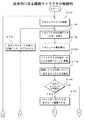
図16及び図17は、従来例に係る難読キャラクタのデコード例(その1,2)を示すフローチャートである。光学情報読取装置20では、CODE128規格に基づくバーコード記号1を読み取って、そのスタートマージンを検索し、更に、スタートマージンに続くキャラクタを2本加算方式によりデコード処理してバーコードデータD12を出力する場合を例に挙げる。その場合のバーコード記号1のバー及びスペースの各エレメントの誤差許容度(最大誤差範囲)が、例えば、±0.5モジュールに設定される。
FIGS. 16 and 17 are flowcharts showing decoding examples (
これらをデコード条件にして、図16に示すフローチャートのステップST81でCPU33はスタートマージンを検索する。このとき、光学読取部2は、バーコード記号1を読み取って、コード読取データD2を発生する。コード読取データD2は、光学読取部2からカウンタ部40へ出力される。クロック発生部3は、所定周波数のサンプリングク用のCLK信号をカウンタ部40に出力する。
Using these as decoding conditions, the CPU 33 searches for a start margin in step ST81 of the flowchart shown in FIG. At this time, the
カウンタ部40は光学読取部2から出力されるコード読取データD2を入力すると共に、クロック発生部3から出力されるCLK信号を入力し、CLK信号に基づいてコード読取データD2をカウントし、コード読取データD2を白部分のスペースおよび黒部分のバーを含むエレメントの2本加算幅を示すカウントデータD4に変換する。カウントデータD4は、バーコード記号1における各バー(黒部分)の幅およびスペース(白部分)の幅を示す数値データ列となる。カウントデータD4は、カウントデータ値格納部30に保存される。
The
m段データバッファ5はカウンタ部40から出力されるカウントデータD4を、m段分(mは任意の整数)だけ一時格納する。m段は、バーコード記号1の印刷状態により任意に設定されている。x倍器7は、カウントデータD4からスタートマージンを検索するに当たり、カウントデータD4を何倍かを示す「x」が予め設定され、そのx倍の演算を行って、x倍データD7を出力する。
The m-
セレクタ部6は、CPU33の選択制御を受けて、m段データバッファ5に一時格納されたm段分のカウントデータD4のうち、比較対象とするデータを選択する。比較器8はセレクタ部6が選択した、m段データバッファ5中のk段前までの各カウントデータD4と、x倍器7から出力されるx倍データD7とを比較する。
Under the selection control of the CPU 33, the
比較結果によってx倍器7からのx倍データD7の方が小さいときは、スタートマージン候補があったと判定し、スタートマージン候補検索フラグ(以下でSMFデータD9という)を発生する。SMFデータD9はスタートマージン格納部9に出力される。スタートマージン格納部9には比較器8から出力されるSMFデータD9、そのとき比較対象としたカウントデータ値=D10とが対応させて格納される。
If the x-fold data D7 from the
ステップST82でCPU33は1キャラクタ分の幅データ(6本)を抽出する。図15に示したキャラクタC1によれば、黒部分のバー(1)の幅W11がカウンタ部40により計数され、そのカウントデータ値が幅W11データとなる。バー(1)に続く白部分のスペース(2)の幅W12もカウンタ部40により計数され、そのカウントデータ値が幅W12データとなる。スペース(2)に続くバー(3)の幅W13はカウンタ部40により計数され、そのカウントデータ値が幅W13データとなる。
In step ST82, the CPU 33 extracts width data (6 pieces) for one character. According to the character C1 shown in FIG. 15, the width W11 of the black portion bar (1) is counted by the
このバー(3)に続くスペース(4)の幅W14もカウンタ部40により計数され、そのカウントデータ値は幅W14データとなる。スペース(4)に続くバー(5)の幅W15はカウンタ部40により計数され、そのカウントデータ値が幅W15データとなる。バー(5)に続くスペース(6)の幅W16もカウンタ部40により計数され、そのカウントデータ値が幅W16データとなる。上述の6種類の幅W11データ〜幅W16データはバーコードデータ値D30を構成する。バーコードデータ値D30はインターフェース部11を介してCPU23に出力される。
The
ステップST83でCPU33はキャラクタC1の1モジュール幅を算出する。この例では、CPU33は、1キャラクタ分の6本の幅W11データ〜幅W16データのバーコードデータ値D30をキャラクタのモジュール数に換算して2本加算パターンのモジュール数を求めている。図15Eに示したように、カウンタ部40のカウントデータ値から、5種類の幅W21データ〜幅W25データがCPU33に順次出力される。
In step ST83, the CPU 33 calculates one module width of the character C1. In this example, the CPU 33 obtains the number of modules of the two-addition pattern by converting the barcode data value D30 of six widths W11 data to width W16 data for one character into the number of character modules. As shown in FIG. 15E, five types of width W21 data to width W25 data are sequentially output to the CPU 33 from the count data value of the
例えば、CPU33は幅W21データを入力し、キャラクタC1のバー(1)とスペース(2)とを加算した加算幅W21のモジュール数を求める。モジュール数は全キャラクタ幅=11モジュールに対する加算幅W21の比率、例えば、2.4を算出する。この場合、加算幅W21のモジュール数は、バーやスペース等の各エレメントの最大誤差が0.5以内となるように、当該モジュール数を四捨五入して最も近い整数になされる。例えば、W21のモジュール数が2.4の場合、W21のモジュール数は「2」である。モジュール数が2.6の場合、W21のモジュール数は「3」である。 For example, the CPU 33 inputs the width W21 data, and obtains the number of modules of the added width W21 obtained by adding the bar (1) and the space (2) of the character C1. As the number of modules, the ratio of the added width W21 to the total character width = 11 modules, for example, 2.4 is calculated. In this case, the number of modules of the addition width W21 is rounded to the nearest integer so that the maximum error of each element such as a bar or space is within 0.5. For example, when the number of modules of W21 is 2.4, the number of modules of W21 is “2”. When the number of modules is 2.6, the number of modules of W21 is “3”.
ステップST84でCPU33は1キャラクタ分のバーコードデータ値D30を2本加算パターンに変換する。例えば、図15Eに示したキャラクタC1のバー(1)とスペース(2)の各々がCPU33によって加算された加算幅W21を示すカウントデータ値が幅W21データとなる。キャラクタC1のバー(1)に続くスペース(2)及びバー(3)の各々がCPU33によって加算された加算幅W22を示すカウントデータ値が幅W22データとなる。 In step ST84, the CPU 33 converts the barcode data value D30 for one character into a two-piece addition pattern. For example, the counted data value indicating the added width W21 obtained by adding the bar (1) and the space (2) of the character C1 shown in FIG. 15E by the CPU 33 is the width W21 data. The counted data value indicating the added width W22 obtained by adding the space (2) and the bar (3) following the bar (1) of the character C1 by the CPU 33 is the width W22 data.
キャラクタC1のスペース(2)に続くバー(3)及びスペース(4)の各々がCPU33によって加算された加算幅W23を示すカウントデータ値が幅W23データとなる。キャラクタC1のバー(3)に続くスペース(4)及びバー(5)の各々がCPU33によって加算された加算幅W24を示すカウントデータ値が幅W24データとなる。キャラクタC1のスペース(4)に続くバー(5)及びスペース(6)の各々がCPU33によって加算された加算幅W25を示すカウントデータ値が幅W25データとなる。 The counted data value indicating the added width W23 in which the bar (3) and the space (4) following the space (2) of the character C1 are added by the CPU 33 is the width W23 data. The counted data value indicating the added width W24 obtained by adding the space (4) and the bar (5) following the bar (3) of the character C1 by the CPU 33 is the width W24 data. The counted data value indicating the added width W25 obtained by adding the bar (5) and the space (6) following the space (4) of the character C1 by the CPU 33 is the width W25 data.
その後、ステップST85でCPU33は、先に変換した2本加算パターンが一致するキャラクタを検索する。この例では、図14に示したカウンタ部40から出力されるバーコードデータ値D30に基づいて、CPU33が5種類の幅W21データ〜幅W25データ(2本加算データ)に関して、先に変換されたモジュール値と、期待値キャラクタの理論値とが一致するキャラクタを検索する。従来方式では、この段階でキャラクタが決定する。
Thereafter, in step ST85, the CPU 33 searches for a character that matches the previously converted two-addition pattern. In this example, on the basis of the barcode data value D30 output from the
ステップST86でCPU33は一致するキャラクタの存在有無に基づいて制御を分岐する。一致するキャラクタが存在する場合は、ステップST87で2本加算パターンが一致したキャラクタをデコード結果とする。その後、図17に示すステップST88に移行する。 In step ST86, the CPU 33 branches the control based on the presence / absence of a matching character. If there is a matching character, in step ST87, the character whose two addition patterns match is taken as the decoding result. Thereafter, the process proceeds to step ST88 shown in FIG.
上述のステップST87でデコード結果となされたキャラクタについては、ステップST88で、CPU33はマージン直後のキャラクタか否かに基づいて制御を分岐する。デコード結果となされたキャラクタが、マージン直後のキャラクタではない場合は、ステップST89に移行してCPU33はデコード結果がストップキャラクタか否かに基づいて制御を分岐する。 For the character that is the decoding result in step ST87 described above, in step ST88, the CPU 33 branches the control based on whether or not the character is immediately after the margin. If the decoded character is not a character immediately after the margin, the process proceeds to step ST89, and the CPU 33 branches the control based on whether the decoded result is a stop character.
デコード結果がストップキャラクタではない場合は、ステップST90に移行してCPU33は、誤り検知(パリティチェック)を実行して、チェックデジットが正しいか否かに基づいて制御を分岐する。チェックデジットが正しい場合は、ステップST91でCPU33は読み取りを完了し、デコードバッファ25のバーコードデータD12を出力し、デコードバッファ25をクリアする(正常終了)。その後、ステップST95に移行する。
If the decoded result is not a stop character, the process proceeds to step ST90, where the CPU 33 executes error detection (parity check) and branches control based on whether or not the check digit is correct. If the check digit is correct, the CPU 33 completes reading in step ST91, outputs the barcode data D12 of the
なお、ステップST88でマージン直後のキャラクタである場合は、ステップST92に移行してCPU33は、デコード結果がスタートキャラクタか否かに基づいて制御を分岐する。上述のステップST89でデコード結果がストップキャラクタである場合及び、ステップST92でデコード結果がスタートキャラクタである場合は、図16に示すステップST83に移行する。ステップST83でCPU33は、次キャラクタ(6本後ろのバーコードデータ値D30)のデコード処理を実行する。その後、ステップST81に戻る。 If the character is immediately after the margin in step ST88, the process proceeds to step ST92, and the CPU 33 branches the control based on whether or not the decoding result is a start character. When the decoding result is a stop character in step ST89 and when the decoding result is a start character in step ST92, the process proceeds to step ST83 shown in FIG. In step ST83, the CPU 33 executes a decoding process of the next character (six bar code data values D30). Thereafter, the process returns to step ST81.
また、図16に示したステップST86で一致するキャラクタが存在しない場合、図17に示したステップST92でデコード結果がスタートキャラクタではない場合及び、ステップST90でチェックデジットが誤っている場合は、ステップST94に移行してCPU33は、読み取りエラー処理を実行する。読み取りエラー処理では次のマージンを検索する等が行われる。 Also, if there is no matching character in step ST86 shown in FIG. 16, if the decoding result is not a start character in step ST92 shown in FIG. 17, or if the check digit is incorrect in step ST90, step ST94. Then, the CPU 33 executes read error processing. In the reading error process, the next margin is searched.
その後、ステップST95に移行して、CPU33は終了を判別する。例えば、当該光学情報読取装置20に対して読取終了指令が検出され、読取終了指令が検出された場合は、バーコード記号1の読み取り制御を終了する。読取終了指令が検出されていない場合は、バーコード記号1の読み取り制御を継続するべく、ステップST81に戻って、上述した内容を繰り返すようになされる。
Thereafter, the process proceeds to step ST95, and the CPU 33 determines the end. For example, when a reading end command is detected for the optical
ところで、従来例に係る光学情報読取装置20によれば、特許文献1に見られるようなバーコード記号読取装置の構成に、1キャラクタに関して、2本幅加算方式を導入して難読キャラクタをデコード可能な光学情報読取装置を作成しようとした場合、次のような問題がある。
i.従来方式の光学情報読取装置20では、キャラクタパターン算出時、バー及びスペースを含む各エレメントの誤差許容度が±0.5モジュール以内に設定され、1キャラクタ分の6本の幅W11データ〜幅W16データのバーコードデータ値D30がキャラクタのモジュール数に換算されて、2本加算パターンのモジュール数が求められている。しかも、バーやスペース等の各エレメントの最大誤差が0.5以内となるように、2本加算パターンのモジュール数が四捨五入して最も近い整数になされている。
By the way, according to the optical
i. In the conventional
従って、加算幅W21のキャラクタのモジュール数の計数値が2.4の場合、本来、整数の候補として「2」と「3」となるにも関わらず、モジュール数が四捨五入されて最も近い整数として、モジュール数が「2」となされてしまう(ステップST83参照)。 Therefore, if the count value of the number of modules of the character having the added width W21 is 2.4, the number of modules is rounded off to the nearest integer even though it is originally “2” and “3” as integer candidates. The number of modules is set to “2” (see step ST83).
因みに、期待値キャラクタとして、モジュール数が「3」であったような場合であって、印刷技術や貼付技術等によって、バーコード記号を構成するバーやスペースに、欠落や傷等が介在して、モジュール数の計数値が2.4となった場合に、±1.0の誤差が介入する結果となって、バーコード記号を正確に読み取れないという問題がある。誤差が±0.5モジュールを越えるエレメントが存在した場合は、読み取りエラーとなっていた(ステップST94参照)。 By the way, as an expected value character, when the number of modules is “3”, there are missing or scratches in the bar or space constituting the bar code symbol due to printing technology or pasting technology. When the count value of the number of modules is 2.4, there is a problem that an error of ± 1.0 intervenes and the barcode symbol cannot be read accurately. If there was an element with an error exceeding ± 0.5 module, a reading error occurred (see step ST94).
ii.また、キャラクタパターン検索時、5種類の幅W21データ〜幅W25データ(2本加算データ)に対して一致するキャラクタを検索しているが、誤差が±0.5モジュールを越えるエレメントを含むキャラクタは検索対象から除外されてしまう。従って、ステップST83で四捨五入によって誤差を含んだキャラクタを含むキャラクタがデコード結果と決定される場合が想定される。この結果、従来方式のバーコード読み取り方法によると、バーやスペース等のエレメントが傷やかすれた場合に、バーコードを誤読してしまい、バーコードデータを正確に出力することが困難となるという問題がある。 ii. In addition, when searching for a character pattern, a character that matches five types of width W21 data to width W25 data (double added data) is searched, but a character including an element whose error exceeds ± 0.5 modules is detected. It will be excluded from the search target. Therefore, it is assumed that a character including a character including an error by rounding is determined as a decoding result in step ST83. As a result, according to the conventional barcode reading method, when an element such as a bar or space is scratched or faded, the barcode is misread and it becomes difficult to output the barcode data accurately. There is.
そこで、本発明は上述した課題を解決したものであって、従来方式のバーコード読み取り方法に比べてバーコードの誤読取を防止できるようにすると共に、エレメントが傷やかすれた場合であっても、正確なバーコードデータを出力できるようにした光学情報読取装置、光学情報読取方法、コンピュータが読み取り可能なプログラム及び記録媒体を提供することを目的とする。 Therefore, the present invention solves the above-described problems, and can prevent erroneous reading of a barcode as compared with a conventional barcode reading method, and even when an element is scratched or faded. An object of the present invention is to provide an optical information reading apparatus, an optical information reading method, a computer-readable program, and a recording medium that can output accurate barcode data.
上述の課題を解決するために、請求項1に記載の光学情報読取装置は、1キャラクタ内で隣接するバー及びスペースを含むn(n≧2)本のエレメントの幅を加算して2〜n本加算エレメント幅を各々求め、前記2〜n本加算エレメント幅の各々を1キャラクタのモジュール数に換算して当該2〜n本加算エレメント幅のモジュール数を求める演算手段と、前記演算手段によって求められた前記2〜n本加算エレメント幅の各々のモジュール数が誤差1以内の整数となる対象キャラクタを絞り込んで候補キャラクタを抽出する抽出手段と、前記抽出手段によって抽出された各々の前記2〜n本加算エレメント幅のモジュール数の候補キャラクタと、当該候補キャラクタを評価するための期待値キャラクタとを比較し、当該候補キャラクタと最も相関が強い期待値キャラクタを検索する検索手段とを備えることを特徴とするものである。
In order to solve the above-described problem, the optical information reading apparatus according to
請求項1に係る光学情報読取装置によれば、バーコード記号を読み取ってそのデコード結果を出力する場合に、演算手段は、1キャラクタ内で隣接するバー及びスペースを含むn(n≧2)本のエレメントの幅を加算して2〜n本加算エレメント幅を各々求め、この2〜n本加算エレメント幅の各々を1キャラクタのモジュール数に換算して当該2〜n本加算エレメント幅のモジュール数を求める。抽出手段は、演算手段によって求められた2〜n本加算エレメント幅の各々のモジュール数が誤差1以内の整数となるキャラクタを候補キャラクタとして抽出する。これらを前提にして、検索手段が抽出手段によって抽出された各々の2〜n本加算エレメント幅のモジュール数の候補キャラクタと、当該候補キャラクタを評価するための期待値キャラクタとを比較し、当該候補キャラクタと最も相関が強い期待値キャラクタを検索するようになる。 According to the optical information reading apparatus of the first aspect, when the barcode symbol is read and the decoding result is output, the calculation means includes n (n ≧ 2) lines including adjacent bars and spaces in one character. 2 to n element widths are obtained by adding the widths of the elements, and each of the 2 to n element widths is converted into the number of modules of one character, and the number of modules having the element width of 2 to n elements is calculated. Ask for. The extraction means extracts, as a candidate character, a character in which the number of modules of each of the 2 to n addition element widths obtained by the calculation means is an integer within an error of 1. Based on these assumptions, the search means compares each of the 2 to n candidate element width candidate characters extracted by the extraction means with the expected value character for evaluating the candidate character, and the candidate An expected value character having the strongest correlation with the character is searched.
この検索によって、複数の候補キャラクタから抽出された候補キャラクタと最も相関が強い期待値キャラクタのバーコードデータを当該バーコード記号の読取時のデコード結果として出力できるようになるので、従来方式のバーコード読み取り方法に比べて大幅にバーコードの誤読取を防止できるようになる。 By this search, the barcode data of the expected value character having the strongest correlation with the candidate character extracted from the plurality of candidate characters can be output as the decoding result at the time of reading the barcode symbol. Compared to the reading method, it is possible to prevent erroneous barcode reading.
請求項2に記載の光学情報読取装置は、請求項1において、前記演算手段は、当該対象キャラクタの前記2〜n本加算エレメント幅を各々求める際に、前記対象キャラクタの前後のキャラクタのバー及びスペースを含むエレメントの幅を加算することを特徴とするものである。
The optical information reader according to
請求項3に記載の光学情報読取装置は、請求項1において、前記抽出手段は、当該対象キャラクタの前記2〜n本加算エレメント幅を各々求める際に、前記1キャラクタ分のn本の幅データと、当該対象キャラクタの前後の1本以上の幅データとを抽出することを特徴とするものである。 According to a third aspect of the present invention, there is provided the optical information reading device according to the first aspect, wherein the extracting unit obtains n width data for the one character when each of the 2 to n additional element widths of the target character is obtained. And one or more width data before and after the target character.
請求項4に記載の光学情報読取装置は、請求項1において、前記検索手段は、前記抽出手段から得られた複数の前記対象キャラクタの各々の前記2〜n本加算エレメント幅に対して2種類の前記対象キャラクタの何れかと一致する対象キャラクタを検索し、前記候補キャラクタの数を絞り込むことを特徴とするものである。 An optical information reading apparatus according to a fourth aspect of the present invention is the optical information reading apparatus according to the first aspect, wherein the search means has two types for the 2 to n addition element widths of the plurality of target characters obtained from the extraction means. A target character that matches any of the target characters is searched, and the number of candidate characters is narrowed down.
請求項5に記載の光学情報読取装置は、請求項1において、前記検索手段は、前記候補キャラクタのモジール数の実測値と、前記期待値キャラクタのモジール数の理想値との間の誤差を算出し、前記誤差を合計して得られる誤差値が最小となる前記候補キャラクタと最も相関が強い期待値キャラクタを検索することを特徴とするものである。
The optical information reader according to
請求項6に記載の光学情報読取装置は、請求項5において、前記検索手段は、前記誤差値が最小となる前記候補キャラクタと一致する前記期待値キャラクタを検出することを特徴とするものである。
The optical information reader according to
請求項7に記載の光学情報読取装置は、請求項1において、前記1キャラクタ内で隣接するバー及びスペースを含むn(n≧2)本のエレメントの幅を加算した合計値と、前記1キャラクタの全幅を示す全幅値とを比較し、比較結果に基づいて当該1キャラクタ分の幅データが適切か否かを判別する比較手段を備えることを特徴とするものである。
The optical information reading device according to
請求項8に記載の光学情報読取方法は、光学情報読取装置が、1キャラクタ内で隣接するバー及びスペースを含むn(n≧2)本のエレメントの幅を加算して2〜n本加算エレメント幅を各々求めるステップと、求めた前記2〜n本加算エレメント幅の各々を1キャラクタのモジュール数に換算して当該2〜n本加算エレメント幅のモジュール数を求めるステップと、求めた前記2〜n本加算エレメント幅の各々のモジュール数が誤差1以内の整数となる対象キャラクタを絞り込んで候補キャラクタを抽出するステップと、抽出された各々の前記2〜n本加算エレメント幅のモジュール数の候補キャラクタと、当該候補キャラクタを評価するための期待値キャラクタとを比較し、当該候補キャラクタと最も相関が強い期待値キャラクタを検索するステップとを実行することを特徴とするものである。
The optical information reading method according to
請求項9に記載の光学情報読取方法は、請求項8において、当該対象キャラクタの前記2〜n本加算エレメント幅を各々求める際に、前記対象キャラクタの前後のキャラクタのバー及びスペースを含むエレメントの幅を加算することを特徴とするものである。 An optical information reading method according to a ninth aspect is the method according to the eighth aspect, wherein in calculating each of the 2 to n additional element widths of the target character, the elements including the bars and spaces of the characters before and after the target character. The width is added.
請求項10に記載の光学情報読取方法は、請求項9において、前記2〜n本加算エレメント幅を各々求める際に、前記1キャラクタ分のn本の幅データと、当該キャラクタの前後の1本以上の幅データとを抽出することを特徴とするものである。 The optical information reading method according to a tenth aspect of the present invention is the optical information reading method according to the ninth aspect, wherein the width data for the one character and the one before and after the character are obtained when the 2-n additional element widths are obtained. The above width data is extracted.
請求項11に記載の光学情報読取方法は、請求項10において、抽出された複数の前記対象キャラクタの各々の前記2〜n本加算エレメント幅に対して2種類の前記対象キャラクタの何れかと一致する対象キャラクタを検索し、前記候補キャラクタの数を絞り込むことを特徴とするものである。 An optical information reading method according to an eleventh aspect of the present invention is the optical information reading method according to the tenth aspect, which matches any of the two types of the target character with respect to the 2 to n addition element widths of the plurality of extracted target characters. The target character is searched and the number of candidate characters is narrowed down.
請求項12に記載の光学情報読取方法は、請求項8において、前記候補キャラクタのモジール数の実測値と、前記期待値キャラクタのモジール数の理想値との間の誤差を算出し、前記誤差を合計して得られる誤差値が最小となる前記候補キャラクタと最も相関が強い期待値キャラクタを抽出することを特徴とするものである。 An optical information reading method according to a twelfth aspect of the present invention is the optical information reading method according to the eighth aspect, wherein an error between an actually measured value of the number of modules of the candidate character and an ideal value of the number of modules of the expected value character is calculated. An expected value character having the strongest correlation with the candidate character having the smallest error value obtained by summing is extracted.
請求項13に記載の光学情報読取方法は、請求項12において、前記誤差値が最小となる前記候補キャラクタと一致する前記期待値キャラクタを検出することを特徴とするものである。 An optical information reading method according to a thirteenth aspect is characterized in that in the twelfth aspect, the expected value character that matches the candidate character having the smallest error value is detected.
請求項14に記載の光学情報読取方法は、請求項8において、前記1キャラクタ内で隣接するバー及びスペースを含むn(n≧2)本のエレメントの幅を加算した合計値と、前記1キャラクタの全幅を示す全幅値とを比較し、比較結果に基づいて当該1キャラクタ分の幅データが適切か否かを判別することを特徴とするものである。
The optical information reading method according to claim 14 is the optical information reading method according to
請求項15に記載のコンピュータが読み取り可能なプログラムは、請求項8乃至14に記載の光学情報読取方法を実行するための指令を組み合わせたことを特徴とするものである。 A computer-readable program according to a fifteenth aspect is characterized by combining commands for executing the optical information reading method according to the eighth to fourteenth aspects.
請求項16に記載のコンピュータが読み取り可能な記録媒体は、請求項8乃至14に記載の光学情報読取方法を実行するためのプログラムが記述されていることを特徴とするものである。 According to a sixteenth aspect of the present invention, there is provided a computer-readable recording medium in which a program for executing the optical information reading method according to the eighth to fourteenth aspects is described.
請求項1に係る光学情報読取装置及び、請求項8に係る光学情報読取方法によれば、2〜n本加算エレメント幅の各々のモジュール数が誤差1以内の整数となる対象キャラクタを絞り込んで候補キャラクタが抽出され、ここに抽出された各々の2〜n本加算エレメント幅のモジュール数の候補キャラクタと、当該候補キャラクタを評価するための期待値キャラクタとを比較し、当該候補キャラクタと最も相関が強い期待値キャラクタを検索する検索手段を備えるものである。
According to the optical information reading apparatus according to
この構成によって、複数の候補キャラクタから抽出された候補キャラクタと最も相関が強い期待値キャラクタのバーコードデータを当該バーコード記号の読取時のデコード結果として出力できるようになるので、従来方式のバーコード読み取り方法に比べて大幅にバーコードの誤読取を防止できるようになる。 With this configuration, barcode data of an expected value character having the strongest correlation with candidate characters extracted from a plurality of candidate characters can be output as a decoding result at the time of reading the barcode symbol. Compared to the reading method, it is possible to prevent erroneous barcode reading.
請求項2に記載の光学情報読取装置及び、請求項9に記載の光学情報読取方法によれば、当該対象キャラクタの2〜n本加算エレメント幅を各々求める際に、対象キャラクタの前後のキャラクタのバー及びスペースを含むエレメントの幅を加算するので、複数の候補キャラクタから抽出された候補キャラクタと最も相関が強い期待値キャラクタのバーコードデータを当該バーコード記号の読取時のデコード結果として出力できるようになる。
According to the optical information reading device according to
請求項3に記載の光学情報読取装置及び、請求項10に記載の光学情報読取方法によれば、当該対象キャラクタの前記2〜n本加算エレメント幅を各々求める際に、前記1キャラクタ分のn本の幅データと、当該対象キャラクタの前後の1本以上の幅データとを抽出するので、複数の候補キャラクタから抽出された候補キャラクタと最も相関が強い期待値キャラクタのバーコードデータを当該バーコード記号の読取時のデコード結果として出力できるようになる。
According to the optical information reading apparatus according to
また、請求項3に係る光学情報読取装置及び請求項10に係る光学情報読取方法によれば、1キャラクタ分のn本の幅データと、当該キャラクタの前後の1本以上の幅データとを抽出するので、2〜n本加算エレメント幅の各々のモジュール数が誤差1以内の整数となる候補キャラクタを従来方法に比べてより多く抽出できるようになり、第1番目に相関が強いものをデコード結果とするだけでなく、第2番目、第3番目・・・に相関が強いものがデコード結果となる確率が高くなるというようにデコード結果の候補キャラクタを複数出力できるようになる。
Further, according to the optical information reading device according to
請求項4に記載の光学情報読取装置及び、請求項11に記載の光学情報読取方法によれば、抽出された複数の前記対象キャラクタの各々の前記2〜n本加算エレメント幅に対して2種類の前記対象キャラクタの何れかと一致する対象キャラクタを検索し、候補キャラクタの数を絞り込むので、従来方式のバーコード読み取り方法に比べて大幅にバーコードの誤読取を防止できるようになる。
According to the optical information reading device according to
請求項5に記載の光学情報読取装置及び、請求項12に記載の光学情報読取方法によれば、誤差値が最小となる候補キャラクタと最も相関が強い期待値キャラクタを検索するので、従来方式のバーコード読み取り方法に比べて大幅にバーコードの誤読取を防止できるようになる。
According to the optical information reading device according to
請求項6に記載の光学情報読取装置及び、請求項13に記載の光学情報読取方法によれば、誤差値が最小となる候補キャラクタと一致する期待値キャラクタを検出するので、従来方式のバーコード読み取り方法に比べて大幅にバーコードの誤読取を防止できるようになる。
According to the optical information reading device according to
請求項7に記載の光学情報読取装置及び、請求項14に記載の光学情報読取方法によれば、当該1キャラクタ分の幅データが適切か否かの判別結果に基づいてキャラクタのバーの消失や分割等を判断できるようになる。複数のスキャンのデコード結果を組み合わせることが可能となり、汚れや、かすれがひどいバーコードにおいても読み取りが可能となる。
According to the optical information reading device according to
請求項15に係るコンピュータが読み取り可能なプログラム及び請求項16に係る記録媒体によれば、本発明に係る光学情報読取方法を実行するための指令を組み合わせたので、複数の候補キャラクタから抽出された候補キャラクタと最も相関が強い期待値キャラクタのバーコードデータを当該バーコード記号の読取時のデコード結果として出力できるようになる。従って、従来方式のバーコード読み取り方法に比べて大幅にバーコードの誤読取を防止できるようになる。 According to the computer-readable program according to claim 15 and the recording medium according to claim 16, since the command for executing the optical information reading method according to the present invention is combined, it is extracted from a plurality of candidate characters. The barcode data of the expected value character having the strongest correlation with the candidate character can be output as the decoding result when the barcode symbol is read. Therefore, bar code reading errors can be greatly prevented as compared with the conventional bar code reading method.
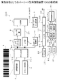
以下、図面を参照しながら、本発明に係る光学情報読取装置、光学情報読取方法、コンピュータが読み取り可能なプログラム及び記録媒体について説明する。図1に示すバーコード記号読取装置100は光学情報読取装置の一例を構成し、バーコード記号1を読み取って、そのスタートマージンを検索し、更に、スタートマージンに続くキャラクタをデコード処理してバーコードデータD12を出力するものである。
Hereinafter, an optical information reading apparatus, an optical information reading method, a computer-readable program, and a recording medium according to the present invention will be described with reference to the drawings. A bar code
バーコード記号読取装置100は、光学読取部2、クロック発生部3、カウンタ部4、m段データバッファ5、x倍器7、セレクタ部6、比較器8、スタートマージン格納部9、幅データ格納部10、インターフェース部11、マイクロプロセッサ12及びデコードバッファ25を有して構成される。なお、従来例と同じ名称及び同じ符号のものは同じ機能を有するのでその説明を省略する。
The bar code
カウンタ部4は光学読取部2から出力されるコード読取データD2を入力すると共に、クロック発生部3から出力されるCLK信号を入力し、当該CLK信号に基づいてコード読取データD2をカウントし、コード読取データD2を白部分のスペースおよび黒部分のバーを含むエレメントの1本幅や、n本加算幅を示すカウントデータD4(バーコードデータ値:数値)に変換する。
The
カウンタ部4には幅データ格納部10が接続される。幅データ格納部10は、カウンタ部4から順次出力される1本幅、n本加算幅の対象キャラクタに係るカウントデータD4を、時系列的にすべて格納して保存する。幅データ格納部10は、フリップフロップ回路や、DRAM等のような記憶回路から構成される。幅データ格納部10は、1本幅、n本加算幅の対象キャラクタに係るカウントデータD4を各キャラクタの幅データD10(バーコードデータ値D30に対応)として出力する。スタートマージン格納部9及び幅データ格納部10にはインターフェース部11が接続される。
A width
マイクロプロセッサ12は、インターフェース部11を介して入力されるSMFデータD9や、各キャラクタの幅データD10によって、バーコードの認識処理を実行する。マイクロプロセッサ12は、プログラム格納用の読み出し専用メモリ(Read Only Memory:以下ROM21という)、ワークメモリ用の随時情報の書き込み読出し可能なメモリ(Random Access Memory:以下RAM22という)、及び中央処理ユニット(Central Processing Unit;以下CPU23という)及び期待値格納部24を含むマイクロコンピュータを構成している。
The microprocessor 12 executes barcode recognition processing based on the SMF data D9 input via the
ROM21は記録媒体の一例を構成する。ROM21にはコンピュータが読み取り可能なプログラムであって、本発明に係る光学情報読取方法を実行するための指令を組み合わせたプログラムデータDpが格納される。その内容は、バーコード記号読取装置100が、1キャラクタ内で隣接するバー及びスペースを含むn(n≧2)本のエレメントの幅を加算して2〜n本加算エレメント幅を各々求めるステップと、求めた2〜n本加算エレメント幅の各々を1キャラクタのモジュール数に換算して当該2〜n本加算エレメント幅のモジュール数を求めるステップと、ここで求めた2〜n本加算エレメント幅の各々のモジュール数が誤差1以内の整数となる対象キャラクタを絞り込んで候補キャラクタを抽出するステップと、抽出された各々の2〜n本加算エレメント幅のモジュール数の候補キャラクタと、当該候補キャラクタを評価するための期待値キャラクタとを比較し、当該候補キャラクタと最も相関が強い期待値キャラクタを検索するステップとを実行するプログラムである。ここに候補キャラクタとは対象キャラクタを絞り込んだキャラクタをいう。プログラムデータDpには、システム起動用のシステムプログラムデータも含まれる。
The
RAM22にはバーコード記号読取装置100を制御するためのシステムプログラムの他に、光学情報読取方法を実行するための演算や、抽出、検索、比較等の制御を実行する際の制御情報が一時格納される。例えば、電源がオンされると、電源オン情報を検出したCPU23は、ROM21からシステムプログラムを読み出してRAM22に展開し、システムを起動して、当該バーコード記号読取装置100全体を制御するようになされる。
In addition to the system program for controlling the bar
この例で、CPU23は、少なくとも、演算部23aや、抽出部23b、比較部23c、検索部23d等の4つの機能を有している。演算部23aは演算手段の一例を構成し、各対象キャラクタの幅データD10を入力し、幅データD10に基づいて1キャラクタ内で隣接するバー及びスペースを含むn(n≧2)本のエレメントの幅を加算して2〜n本加算エレメント幅を各々求める。演算部23aは、求めた2〜n本加算エレメント幅の各々を1キャラクタのモジュール数に換算して当該2〜n本加算エレメント幅のモジュール数を求める。
In this example, the
抽出部23bは、演算部23aによって求められた2〜n本加算エレメント幅(以下で2〜n本加算パターンともいう)の各々のモジュール数が誤差1以内の整数となる対象キャラクタを絞り込んで候補キャラクタを抽出する。抽出部23bは、2〜n本加算パターンを各々求める際に、1キャラクタ分のn本の幅データD10と、対象キャラクタの前後の1本以上の幅データD10とを抽出する。
The
この例では、対象キャラクタの抽出基準を従来方式の誤差0.5以内の整数から誤差1以内の整数へと範囲を拡大し、1キャラクタ分のn本の幅データD10と、対象キャラクタの前後の1本以上の幅データD10とを抽出するようにした。従って、2〜n本加算エレメント幅の各々のモジュール数が誤差1以内の整数となる対象キャラクタを従来方法に比べて、より多く抽出できるようになる。しかも、第1番目に相関が強いものをデコード結果とするだけでなく、第2番目、第3番目・・・に相関が強いものがデコード結果となる確率が高くなるというようにデコード結果の候補キャラクタを複数出力できるようになる。これにより、従来方式のバーコード読み取り方法に比べて大幅にバーコードの誤読取を防止できるようになる。 In this example, the target character extraction standard is expanded from an integer with an error of 0.5 or less in the conventional method to an integer with an error of 1 or less, n width data D10 for one character, and before and after the target character. One or more width data D10 are extracted. Therefore, it becomes possible to extract more target characters in which the number of modules of each of the 2 to n addition element widths is an integer within an error of 1 as compared with the conventional method. Moreover, not only the first strongest correlation is used as the decoding result, but also the decoding result candidates such that the second, third,... Multiple characters can be output. As a result, it is possible to largely prevent erroneous barcode reading as compared with the conventional barcode reading method.
比較部23cは、抽出部23bによって抽出された各々の2〜n本加算エレメント幅のモジュール数の候補キャラクタと、当該候補キャラクタを評価するための期待値キャラクタ(理論値)とを比較する。比較部23cは判別機能を有しており、1キャラクタ内で隣接するバー及びスペースを含むn(n≧2)本のエレメントの幅を加算した合計値と、1キャラクタの全幅を示す全幅値とを比較し、比較結果に基づいて当該1キャラクタ分の幅データD10が適切か否かを判別する。
The
この判別によって、キャラクタのバーの消失や分割等を判断できるようになる。また、複数のスキャンのデコード結果を組み合わせることが可能となり、汚れや、かすれがひどいバーコードにおいても読み取りが可能となる。また、バーの消失や分割等の判断結果に基づいて対象キャラクタを絞ることができ、計算量の軽減が図れ、処理時間の高速化につながる。 This determination makes it possible to determine the disappearance or division of the character bar. In addition, it is possible to combine the decoding results of a plurality of scans, and it is possible to read even a barcode that is very dirty or faint. In addition, the target character can be narrowed down based on the determination result such as disappearance or division of the bar, the calculation amount can be reduced, and the processing time can be increased.
検索部23d 検索部23dは、候補キャラクタと最も相関が強い期待値キャラクタを検索する。例えば、上述の演算部23aが候補キャラクタのモジール数の実測値と、期待値キャラクタのモジール数の理想値との間の誤差を算出すると、検索部23dが、演算部23aによって算出された誤差を合計して得られる誤差値が最小となる候補キャラクタと最も相関が強い期待値キャラクタを検索する。この例では、誤差値が最小となる候補キャラクタと最も相関が強い期待値キャラクタを検索するので、従来方式のバーコード読み取り方法に比べて大幅にバーコードの誤読取を防止できるようになる。
Search unit 23d The search unit 23d searches for an expected value character having the strongest correlation with the candidate character. For example, when the
マイクロプロセッサ12には期待値格納部24が接続される。期待値格納部24には期待値キャラクタ(理論値)が格納されている。期待値キャラクタはCODE128規格のキャラクタの各エレメントを構成するモジュール数(理論値)である。これらにより、バーコード記号読取装置100を構成する。CPU23内の演算部23a、抽出部23b、比較部23c及び、検索部23dはソフトウエアでも、ハードウェアでもどちらで構築してもよい。
An expected value storage unit 24 is connected to the microprocessor 12. The expected value storage unit 24 stores expected value characters (theoretical values). The expected value character is the number of modules (theoretical value) constituting each element of the CODE128 standard character. Thus, the bar code
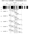
続いて、図2A〜Gを参照して、第1の実施例に係る1本データ、2〜6本加算データの算出例について説明する。この実施例では、CODE128規格のバーコード記号1について説明する。CODE128規格によれば、図2Aに示す1キャラクタは、3本の黒部分のバー(1),(3),(5)及び3本の白部分のスペース(2),(4),(6)から構成される。図中、C1は対象キャラクタであり、C0は対象キャラクタC1の1つ前のキャラクタであり、C2はその1つ後ろのキャラクタである。
Next, with reference to FIGS. 2A to 2G, a calculation example of the single data and the 2-6 additional data according to the first embodiment will be described. In this embodiment, the
1キャラクタの全幅は11モジュールから構成される。この例で、黒部分のバー(1)は4モジュールから成り、バー(3)及びバー(5)は各々1モジュールから成る。白部分のスペース(2)は4モジュールから成り、スペース(4)及び(6)は各々2モジュールから成る。 The full width of one character is composed of 11 modules. In this example, the black bar (1) consists of 4 modules, and the bars (3) and (5) each consist of 1 module. The white space (2) consists of 4 modules, and the spaces (4) and (6) each consist of 2 modules.
スタートコードは3種類あり、それぞれ103種類のコードパターンが表される。CODE128規格では、アスキー128文字を表現できるようになっている。スタートコードCを使用すれば、1キャラクタで数字2桁を表現でき、非常に高い印字密度で表現できる。CODE128のバーコード記号1は8キャラクタから構成される(図5A参照)。バーに用いるモジュール数の和は偶数パリティであり、スペースに用いるモジュール数の和は奇数パリティとなっている。偶数パリティ及び奇数パリティを利用した自己機能を持っている。
There are three types of start codes, each representing 103 types of code patterns. In the CODE128 standard, ASCII 128 characters can be expressed. If the start code C is used, two digits can be expressed with one character, which can be expressed with a very high printing density. The
図2Bに示すW11は対象キャラクタC1の黒部分のバー(1)の幅である。バー(1)の幅はカウンタ部4により計数され、そのカウントデータ値は幅W11データを成す。W12はバー(1)に続くスペース(2)の幅である。スペース(2)の幅もカウンタ部4により計数され、そのカウントデータ値は幅W12データを成す。W13は対象キャラクタC1のスペース(2)に続くバー(3)の幅である。バー(3)の幅はカウンタ部4により計数され、そのカウントデータ値は幅W13データを成す。
W11 shown in FIG. 2B is the width of the black bar (1) of the target character C1. The width of the bar (1) is counted by the
W14は対象キャラクタC1のバー(3)に続くスペース(4)の幅である。スペース(4)の幅もカウンタ部4により計数され、そのカウントデータ値は幅W14データを成す。W15はスペース(4)に続くバー(5)の幅である。バー(5)の幅はカウンタ部4により計数され、そのカウントデータ値は幅W15データを成す。W16は対象キャラクタC1のバー(5)に続くスペース(6)の幅である。スペース(6)の幅もカウンタ部4により計数され、そのカウントデータ値は幅W16データを成す。上述の6種類の幅W11データ〜幅W16データは1キャラクタの1本データであり、幅データD10を構成する。
W14 is the width of the space (4) following the bar (3) of the target character C1. The width of the space (4) is also counted by the
図2Cに示すW21は対象キャラクタC1のバー(1)とスペース(2)の各々が演算部23aによって加算された幅(以下バー(1)+スペース(2)と記す)である。バー(1)+スペース(2)の加算幅を示すカウントデータ値は幅W21データを成す。W22は対象キャラクタC1のバー(1)に続くスペース(2)及びバー(3)の各々が演算部23aによって加算された幅である。スペース(2)+バー(3)の加算幅を示すカウントデータ値は幅W22データを成す。
W21 shown in FIG. 2C is a width obtained by adding the bar (1) and the space (2) of the target character C1 by the
W23は対象キャラクタC1のスペース(2)に続くバー(3)及びスペース(4)の各々が演算部23aによって加算された幅である。バー(3)+スペース(4)の加算幅を示すカウントデータ値は幅W23データを成す。W24は対象キャラクタC1のバー(3)に続くスペース(4)及びバー(5)の各々が演算部23aによって加算された幅である。スペース(4)+バー(5)の加算幅を示すカウントデータ値は幅W24データを成す。W25は対象キャラクタC1のスペース(4)に続くバー(5)及びスペース(6)の各々が演算部23aによって加算された幅である。バー(5)+スペース(6)の加算幅を示すカウントデータ値は幅W25データを成す。上述の5種類の幅W21データ〜幅W25データは1キャラクタの2本加算データであり、幅データD10を構成する。
W23 is a width obtained by adding the bar (3) and the space (4) following the space (2) of the target character C1 by the
図2Dに示すW31は対象キャラクタC1のバー(1)、スペース(2)及びバー(3)の各々が演算部23aによって加算された幅である。バー(1)+スペース(2)+バー(3)の加算幅を示すカウントデータ値は幅W31データを成す。W32は対象キャラクタC1のバー(1)に続くスペース(2)、バー(3)及びスペース(4)の各々が演算部23aによって加算された幅である。スペース(2)+バー(3)+スペース(4)の加算幅を示すカウントデータ値は幅W32データを成す。
W31 shown in FIG. 2D is a width obtained by adding each of the bar (1), the space (2), and the bar (3) of the target character C1 by the
W33は対象キャラクタC1のスペース(2)に続くバー(3)、スペース(4)及びバー(5)の各々が演算部23aによって加算された幅である。バー(3)+スペース(4)+バー(5)の加算幅を示すカウントデータ値は幅W33データを成す。W34は対象キャラクタC1のバー(3)に続くスペース(4)、バー(5)及びスペース(6)の各々が演算部23aによって加算された幅である。スペース(4)+バー(5)+スペース(6)の加算幅を示すカウントデータ値は幅W34データを成す。上述の4種類の幅W31データ〜幅W34データは1キャラクタの3本加算データであり、幅データD10を構成する。
W33 is a width obtained by adding the bar (3), the space (4), and the bar (5) following the space (2) of the target character C1 by the
図2Eに示すW41は対象キャラクタC1のバー(1)、スペース(2)、バー(3)及びスペース(4)の各々が演算部23aによって加算された幅である。バー(1)+スペース(2)+バー(3)+スペース(4)の加算幅を示すカウントデータ値は幅W41データを成す。W42の対象キャラクタC1はバー(1)に続くスペース(2)、バー(3)、スペース(4)及びバー(5)の各々が演算部23aによって加算された幅である。スペース(2)+バー(3)+スペース(4)+バー(5)の加算幅を示すカウントデータ値は幅W42データを成す。
W41 shown in FIG. 2E is a width obtained by adding each of the bar (1), the space (2), the bar (3), and the space (4) of the target character C1 by the
W43は対象キャラクタC1のスペース(2)に続くバー(3)、スペース(4)、バー(5)及びスペース(6)の各々が演算部23aによって加算された幅である。バー(3)+スペース(4)+バー(5)+スペース(6)の加算幅を示すカウントデータ値は幅W43データを成す。上述の3種類の幅W41データ〜幅W43データは1キャラクタの4本加算データであり、幅データD10を構成する。
W43 is the width obtained by adding the bar (3), the space (4), the bar (5), and the space (6) following the space (2) of the target character C1 by the
図2Fに示すW51は対象キャラクタC1のバー(1)、スペース(2)、バー(3)、スペース(4)及びバー(5)の各々が演算部23aによって加算された幅である。バー(1)+スペース(2)+バー(3)+スペース(4)+バー(5)の加算幅を示すカウントデータ値は幅W51データを成す。
W51 shown in FIG. 2F is a width obtained by adding the bar (1), space (2), bar (3), space (4), and bar (5) of the target character C1 by the
W52は対象キャラクタC1のバー(1)に続くスペース(2)、バー(3)、スペース(4)、バー(5)及びスペース(6)の各々が演算部23aによって加算された幅である。スペース(2)+バー(3)+スペース(4)+バー(5)+スペース(6)の加算幅を示すカウントデータ値は幅W52データを成す。上述の2種類の幅W51データ及び幅W52データは1キャラクタの5本加算データであり、幅データD10を構成する。
W52 is a width obtained by adding the space (2), the bar (3), the space (4), the bar (5), and the space (6) following the bar (1) of the target character C1 by the
図2Gに示すW61は対象キャラクタC1のバー(1)、スペース(2)、バー(3)、スペース(4)、バー(5)及びスペース(6)の各々が演算部23aによって加算された幅である。バー(1)+スペース(2)+バー(3)+スペース(4)+バー(5)+スペース(6)の加算幅を示すカウントデータ値は幅W61データを成す。1種類の幅W61データは1キャラクタの6本加算データであり、幅データD10を構成する。
W61 shown in FIG. 2G is a width obtained by adding the bar (1), the space (2), the bar (3), the space (4), the bar (5), and the space (6) of the target character C1 by the
上述のカウンタ部4から出力されるカウントデータ値から、6種類の幅W11データ〜幅W16データ(1本データ)、5種類の幅W21データ〜幅W25データ(2本加算データ)、4種類の幅W31データ〜幅W34データ(3本加算データ)、3種類の幅W41データ〜幅W43データ(4本加算データ)、2種類の幅W51データ及び幅W52データ(5本加算データ)及び、1種類の幅W61データ(6本加算データ)の合計で、21種類の対象キャラクタが得られる。
From the count data value output from the
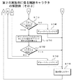
続いて、本発明に係る光学情報読取方法について、図3及び図4を参照し、第1の実施例に係る難読キャラクタのデコード例を説明する。この実施例では、CODE128規格に基づくバーコード記号1を読み取って、そのスタートマージンを検索し、更に、スタートマージンに続く対象キャラクタをデコード処理してバーコードデータD12を出力する場合を例に挙げる。その場合のバーコード記号1のバー及びスペースの各エレメントの誤差許容度(最大誤差範囲)が、±1.0モジュールに設定される。バーコード記号1については図2に示した対象キャラクタC1について説明する(キャラクタデコードアルゴリズム)。
Next, an optical information reading method according to the present invention will be described with reference to FIGS. 3 and 4 and an example of decoding an obfuscated character according to the first embodiment. In this embodiment, an example is described in which the
これらをデコード条件にして、まず、図3に示すフローチャートのステップST1でマイクロプロセッサ12はスタートマージンを検索する。このとき、光学読取部2は、バーコード記号1を読み取って、コード読取データD2を発生する。コード読取データD2は、光学読取部2からカウンタ部4へ出力される。クロック発生部3は、所定周波数のサンプリングク用のCLK信号をカウンタ部4に出力する。
Using these as decoding conditions, first, the microprocessor 12 searches for a start margin in step ST1 of the flowchart shown in FIG. At this time, the
カウンタ部4は光学読取部2から出力されるコード読取データD2を入力すると共に、クロック発生部3から出力されるCLK信号を入力し、CLK信号に基づいてコード読取データD2をカウントし、コード読取データD2を白部分のスペースおよび黒部分のバーを含むエレメントの1本幅及び6本加算幅を示すカウントデータD4に変換する。カウントデータD4は、バーコード記号1における各バー(黒部分)の幅およびスペース(白部分)の幅を示す数値データ列となる。カウントデータD4は、幅データ格納部10に保存される。
The
m段データバッファ5はカウンタ部4から出力されるカウントデータD4を、m段分(mは任意の整数)だけ一時格納する。m段は、バーコード記号1の印刷状態により任意に設定されている。x倍器7は、カウントデータD4からスタートマージンを検索するに当たり、カウントデータD4を何倍かを示す「x」が予め設定され、そのx倍の演算を行って、x倍データD7を出力する。
The m-
セレクタ部6は、マイクロプロセッサ12の選択制御を受けて、m段データバッファ5に一時格納されたm段分のカウントデータD4のうち、比較対象とするデータを選択する。比較器8はセレクタ部6が選択した、m段データバッファ5中のk段前までの各カウントデータD4と、x倍器7から出力されるx倍データD7とを比較する。
Under the selection control of the microprocessor 12, the
比較結果によってx倍器7からのx倍データD7の方が小さいときは、スタートマージン候補があったと判定し、スタートマージン候補検索フラグ(以下でSMFデータD9という)を発生する。SMFデータD9はスタートマージン格納部9に出力される。スタートマージン格納部9には比較器8から出力されるSMFデータD9、そのとき比較対象としたカウントデータ値=D10とが対応させて格納される。
If the x-fold data D7 from the
ステップST2でCPU23は1キャラクタ分の幅データD10(6本)と、その前後の5本ずつ幅データD10を抽出する。図2Bに示した対象キャラクタC1によれば、黒部分のバー(1)の幅W11がカウンタ部4により計数され、そのカウントデータ値が幅W11データとなる。バー(1)に続く白部分のスペース(2)の幅W12もカウンタ部4により計数され、そのカウントデータ値が幅W12データとなる。スペース(2)に続くバー(3)の幅W13はカウンタ部4により計数され、そのカウントデータ値が幅W13データとなる。
In step ST2, the
このバー(3)に続くスペース(4)の幅W14もカウンタ部4により計数され、そのカウントデータ値は幅W14データとなる。スペース(4)に続くバー(5)の幅W15はカウンタ部4により計数され、そのカウントデータ値が幅W15データとなる。バー(5)に続くスペース(6)の幅W16もカウンタ部4により計数され、そのカウントデータ値が幅W16データとなる。上述の6種類の幅W11データ〜幅W16データは幅データD10を構成する。幅データD10はインターフェース部11を介してCPU23に出力される。
The
CPU23では、演算部23aが各対象キャラクタの幅データD10を入力し、幅データD10に基づいて1キャラクタ内で隣接するバー及びスペースを含むn(n≧2)本のエレメントの幅を加算して2〜n本加算パターンを各々求める。この例ではn=6である。2〜n本加算エレメント幅を各々求める際に、1キャラクタ分の6本の幅データD10と、対象キャラクタの前後の5本の幅データD10とを抽出する。
In the
例えば、図2Cに示した対象キャラクタC1のバー(1)とスペース(2)の各々が演算部23aによって加算され、その加算幅W21を示すカウントデータ値が幅W21データとなる。対象キャラクタC1のバー(1)に続くスペース(2)及びバー(3)の各々が演算部23aによって加算され、その加算幅W22を示すカウントデータ値が幅W22データとなる。対象キャラクタC1のスペース(2)に続くバー(3)及びスペース(4)の各々が演算部23aによって加算され、その加算幅W23を示すカウントデータ値が幅W23データとなる。
For example, the bar (1) and the space (2) of the target character C1 shown in FIG. 2C are added by the
対象キャラクタC1のバー(3)に続くスペース(4)及びバー(5)の各々が演算部23aによって加算され、その加算幅W24を示すカウントデータ値が幅W24データとなる。対象キャラクタC1のスペース(4)に続くバー(5)及びスペース(6)の各々が演算部23aによって加算され、その加算幅W25を示すカウントデータ値が幅W25データとなる。上述の5種類の幅W21データ〜幅W25データは幅データD10を構成する。
Each of the space (4) and the bar (5) following the bar (3) of the target character C1 is added by the
図2Dに示した対象キャラクタC1のバー(1)、スペース(2)及びバー(3)の各々が演算部23aによって加算され、その加算幅W31を示すカウントデータ値が幅W31データとなる。対象キャラクタC1のバー(1)に続くスペース(2)、バー(3)及びスペース(4)の各々が演算部23aによって加算され、その加算幅W32を示すカウントデータ値が幅W32データとなる。
Each of the bar (1), the space (2), and the bar (3) of the target character C1 shown in FIG. 2D is added by the
対象キャラクタC1のスペース(2)に続くバー(3)、スペース(4)及びバー(5)の各々が演算部23aによって加算され、その加算幅W33を示すカウントデータ値が幅W33データとなる。対象キャラクタC1のバー(3)に続くスペース(4)、バー(5)及びスペース(6)の各々が演算部23aによって加算され、その加算幅W34を示すカウントデータ値が幅W34データとなる。上述の4種類の幅W31データ〜幅W34データは幅データD10を構成する。
Each of the bar (3), the space (4), and the bar (5) following the space (2) of the target character C1 is added by the
図2Eに示した対象キャラクタC1のバー(1)、スペース(2)、バー(3)及びスペース(4)の各々が演算部23aによって加算され、その加算幅W41を示すカウントデータ値が幅W41データとなる。対象キャラクタC1はバー(1)に続くスペース(2)、バー(3)、スペース(4)及びバー(5)の各々が演算部23aによって加算され、その加算幅W42を示すカウントデータ値が幅W42データとなる。
Each of the bar (1), the space (2), the bar (3), and the space (4) of the target character C1 shown in FIG. 2E is added by the
対象キャラクタC1のスペース(2)に続くバー(3)、スペース(4)、バー(5)及びスペース(6)の各々が演算部23aによって加算され、その加算幅W43を示すカウントデータ値が幅W43データとなる。上述の3種類の幅W41データ〜幅W43データは幅データD10を構成する。
Each of the bar (3), the space (4), the bar (5), and the space (6) following the space (2) of the target character C1 is added by the
図2Fに示した対象キャラクタC1のバー(1)、スペース(2)、バー(3)、スペース(4)及びバー(5)の各々が演算部23aによって加算され、その加算幅W51を示すカウントデータ値が幅W51データとなる。対象キャラクタC1のバー(1)に続くスペース(2)、バー(3)、スペース(4)、バー(5)及びスペース(6)の各々が演算部23aによって加算され、その加算幅W52を示すカウントデータ値が幅W52データを成す。上述の2種類の幅W51データ及び幅W52データは幅データD10を構成する。
Each of the bar (1), the space (2), the bar (3), the space (4), and the bar (5) of the target character C1 shown in FIG. 2F is added by the
図2Gに示した対象キャラクタC1のバー(1)、スペース(2)、バー(3)、スペース(4)、バー(5)及びスペース(6)の各々が演算部23aによって加算され、その加算幅W61を示すカウントデータ値が幅W61データとなる。1種類の幅W61データは幅データD10を構成する。 Each of the bar (1), the space (2), the bar (3), the space (4), the bar (5), and the space (6) of the target character C1 shown in FIG. The count data value indicating the width W61 becomes the width W61 data. One type of width W61 data constitutes width data D10.
上述のカウンタ部4から出力されるカウントデータ値から、6種類の幅W11データ〜幅W16データ(1本データ)、5種類の幅W21データ〜幅W25データ(2本加算データ)、4種類の幅W31データ〜幅W34データ(3本加算データ)、3種類の幅W41データ〜幅W43データ(4本加算データ)、2種類の幅W51データ及び幅W52データ(5本加算データ)及び、1種類の幅W61データ(6本加算データ)の合計で、21種類の対象キャラクタが得られる。
From the count data value output from the
ステップST3でCPU23は対象キャラクタC1の1モジュール幅を算出する。この例では、演算部23aは、先に求めた2〜6本加算パターン(エレメント幅)の各々を1キャラクタのモジュール数に換算して2〜6本加算パターンのモジュール数を求める。図2B〜Gに示したように、カウンタ部4から出力されるカウントデータ値から、6種類の幅W11データ〜幅W16データ、5種類の幅W21データ〜幅W25データ、4種類の幅W31データ〜幅W34データ、3種類の幅W41データ〜幅W43データ、2種類の幅W51データ及び幅W52データ及び、1種類の幅W61データがCPU23に順次出力される。
In step ST3, the
例えば、演算部23aは幅W21データを入力し、対象キャラクタC1のバー(1)とスペース(2)とを加算した加算幅W21のモジュール数を求める。モジュール数は全キャラクタ幅=11モジュールに対する加算幅W21の比率、例えば、2.4を算出する。この場合、加算幅W21のモジュール数は、バーやスペース等の各エレメントの最大誤差が1.0以内の整数となる対象キャラクタを絞り込んで候補キャラクタを抽出するので、加算幅W21のモジュール数は「2」又は「3」となる。
For example, the
この例では、各エレメントの最大誤差範囲を±1.0モジュール以内に拡張したので、各エレメントの誤差許容度が1.0以内まで許容量を増加できるようになる。許容量を増加したので、対象キャラクタ一致を採る条件を増加できる。これにより、バーコード記号1の誤読取を防止できるようになる。
In this example, since the maximum error range of each element is expanded to within ± 1.0 modules, the allowable amount can be increased until the error tolerance of each element is within 1.0. Since the allowable amount is increased, it is possible to increase the conditions for taking the target character match. As a result, it is possible to prevent erroneous reading of the
ステップST4でCPU23は抽出された21種類の幅データD10を1〜6本加算パターン(エレメント幅)に変換する。この例では、6種類の幅W11データ〜幅W16データが1キャラクタの1本データに変換され、1本データに基づく対象キャラクタC1の被認識パターンとして、1本パターンが作成される。5種類の幅W21データ〜幅W25データは1キャラクタの2本加算データに変換され、2本加算データに基づく対象キャラクタC1の2本加算パターン(被認識パターン)が作成される。4種類の幅W31データ〜幅W34データは1キャラクタの3本加算データに変換され、3本加算データに基づく対象キャラクタC1の3本加算識パターンが作成される。
3種類の幅W41データ〜幅W43データは1キャラクタの4本加算データに変換され、4本加算データに基づく対象キャラクタC1の4本加算パターンが作成される。2種類の幅W51データ及び幅W52データは1キャラクタの5本加算データに変換され、5本加算データに基づく対象キャラクタC1の5本加算パターンが作成される。1種類の幅W61データは1キャラクタの6本加算データに変換され、6本加算データに基づく対象キャラクタC1の6本加算パターンが作成される。
In step ST4, the
The three types of width W41 data to width W43 data are converted into four character addition data for one character, and a four character addition pattern for the target character C1 based on the four character addition data is created. The two types of width W51 data and width W52 data are converted into 5-character addition data for one character, and a 5-addition pattern for the target character C1 based on the 5-addition data is created. One type of width W61 data is converted into six character addition data of one character, and a six character addition pattern of the target character C1 based on the six character addition data is created.
ステップST5でCPU23は対象キャラクタを絞り込むために、1本パターン、2〜6本加算パターンの全てに対してモジュール数の誤差が1以内の対象キャラクタを検索して候補キャラクタを決定する。このとき、CPU23では抽出部23bが、演算部23aによって求められた1本パターン、2〜6本加算パターンの各々のモジュール数が誤差1以内の整数となる対象キャラクタを絞り込んで候補キャラクタを抽出する。その際に、抽出部23bは、演算部23aによって求められた1本パターン、2〜6本加算パターンの1キャラクタ分の6本の幅データD10と、対象キャラクタの前後の(6−1)本の幅データD10とを抽出する。
In step ST5, in order to narrow down the target character, the
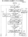
ステップST6でCPU23は、候補キャラクタが1つ以上存在するか否かに基づいて制御を分岐する。対象キャラクタが1つ以上(複数)存在する場合は、ステップST7で1〜6本加算パターンの実測値とその理想値との間の誤差を算出し、この誤差の合計が最小となった候補キャラクタをデコード結果とする。この誤差値が最小となる候補キャラクタは、期待値キャラクタと最も相関が強いキャラクタである。この例では、総合的な誤差が最も少ない対象キャラクタを候補キャラクタとして選択できるようになる。
In step ST6, the
このとき、CPU23では、期待値キャラクタ(理論値)が期待値格納部24からCPU23の比較部23cへ読み出される。比較部23cは、抽出部23bによって抽出された各々の2〜6本加算パターン(エレメント幅)のモジュール数の候補キャラクタと、候補キャラクタを評価するための期待値キャラクタ(理論値)とを比較する。この比較結果は検索部23dへ出力される。
At this time, the
検索部23dでは、候補キャラクタと最も相関が強い期待値キャラクタが検索される。例えば、上述の演算部23aが候補キャラクタのモジール数の実測値と、期待値キャラクタのモジール数の理想値との間の誤差を算出すると、検索部23dが、演算部23aによって算出された誤差を合計して得られる誤差値が最小となる候補キャラクタと最も相関が強い期待値キャラクタを検索する。この例では、誤差値が最小となる候補キャラクタと最も相関が強い期待値キャラクタを検索するので、従来方式のバーコード読み取り方法に比べて大幅にバーコードの誤読取を防止できるようになる。
The search unit 23d searches for an expected value character having the strongest correlation with the candidate character. For example, when the
以後は従来方式と同じ内容となる。例えば、図4に示すステップST8でCPU23は、デコード結果の候補キャラクタがマージン直後の対象キャラクタか否かに基づいて制御を分岐する。デコード結果の候補キャラクタがマージン直後の対象キャラクタである場合は、ステップST9に移行してCPU23はデコード結果の候補キャラクタがストップキャラクタか否かに基づいて制御を分岐する。
Thereafter, the content is the same as the conventional method. For example, in step ST8 shown in FIG. 4, the
デコード結果の候補キャラクタがストップキャラクタではない場合は、ステップST10に移行してCPU23は誤り検知(パリティチェック)を実行し、チェックデジットが正しいか否かに基づいて制御を分岐する。チェックデジットが正しい場合は、読み取りを完了し、ステップST11でCPU23はデコード結果となされた候補キャラクタのバーコードデータD12を出力する。
When the candidate character of the decoding result is not a stop character, the process proceeds to step ST10 where the
なお、ステップST8でCPU23はデコード結果の候補キャラクタがマージン直後の対象キャラクタでない場合は、ステップST12に移行して、CPU23はデコード結果の候補キャラクタがスタートキャラクタか否かに基づいて制御を分岐する。
In step ST8, if the candidate character of the decoding result is not the target character immediately after the margin, the
上述のステップST9でCPU23はデコード結果の候補キャラクタがストップキャラクタである場合及び、ステップST12でデコード結果の候補キャラクタがスタートキャラクタである場合は、図3に示すステップST13に移行する。ステップST13で、CPU23は次キャラクタ(6本後ろのデータ)のデコード処理を実行する。その後、ステップST2に戻る。
In step ST9 described above, if the candidate character of the decoding result is a stop character, and if the candidate character of the decoding result is a start character in step ST12, the
また、ステップST12でデコード結果の候補キャラクタがスタートキャラクタでない場合及び、ステップST10でチェックデジットが誤っている場合は、ステップST14に移行して、CPU23は読み取りエラー処理を実行する。読み取りエラー処理では次のマージンを検索する等が行われる。キャラクタ認識がエラーとなった場合に、エラーキャラクタを仮に配置してバーコードデータを作成するようにしてもよい。
If the decoding result candidate character is not the start character in step ST12 or if the check digit is incorrect in step ST10, the process proceeds to step ST14, and the
その後、ステップST15に移行して、CPU23は終了を判別する。例えば、当該バーコード記号読取装置100に対して読取終了指令が検出され、読取終了指令が検出された場合は、バーコード記号1の読み取り制御を終了する。読取終了指令が検出されていない場合は、バーコード記号1の読み取り制御を継続するべく、ステップST1に戻って、上述した内容を繰り返すようになされる。
Thereafter, the process proceeds to step ST15, and the
このように第1の実施例に係るバーコード記号読取装置100によれば、バーコード記号1を読み取ってそのデコード結果を出力する場合に、演算部23aは、1キャラクタ内で隣接するバー及びスペースを含むn=6(n≧2)本のエレメントの幅を加算して2〜6本加算パターン(エレメント幅)を各々求める。演算部23aは、2〜6本加算パターンの各々を1キャラクタのモジュール数に換算して当該2〜6本加算パターンのモジュール数を求める。
As described above, according to the barcode
抽出部23bは、演算部23aによって求められた2〜6本加算パターンの各々のモジュール数が誤差1以内の整数となる対象キャラクタを絞り込んで候補キャラクタを抽出する。これらを前提にして、検索部23dが抽出部23bによって抽出された各々の2〜6本加算パターンのモジュール数の候補キャラクタと、当該候補キャラクタを評価するための期待値キャラクタとを比較し、当該候補キャラクタと最も相関が強い期待値キャラクタを検索するようになる。
The
この検索によって、複数の対象キャラクタから抽出された候補キャラクタと最も相関が強い期待値キャラクタのバーコードデータD12を当該バーコード記号1の読取時のデコード結果として出力できるようになるので、従来方式のバーコード読み取り方法に比べて大幅にバーコード記号1の誤読取を防止できるようになる。
By this search, the barcode data D12 of the expected value character having the strongest correlation with the candidate character extracted from the plurality of target characters can be output as the decoding result when the
しかも、誤差の範囲を従来方式の±0.5から±1.0に拡大し、候補キャラクタを増加させている。そして、1キャラクタ分の6本の幅データD10と、当該キャラクタC1の前後の5本の幅データD10とを抽出するので、2〜6本加算パターンの各々のモジュール数が誤差1以内の整数となる対象キャラクタを絞り込んだ候補キャラクタを従来方法に比べてより多く抽出できるようになる。 In addition, the error range is expanded from ± 0.5 of the conventional method to ± 1.0, and the number of candidate characters is increased. Since 6 width data D10 for one character and 5 width data D10 before and after the character C1 are extracted, the number of modules in each of the 2 to 6 addition patterns is an integer within an error of 1. It becomes possible to extract more candidate characters narrowing down the target character as compared with the conventional method.
また、第1番目に相関が強い候補キャラクタをデコード結果とするだけでなく、第2番目、第3番目・・・に相関が強い候補キャラクタがデコード結果となる確率が高くなるというようにデコード結果の候補キャラクタを複数出力できるようになる。これにより、従来方式のバーコード読み取り方法に比べて大幅にバーコードの誤読取を防止できるようになる。これにより、従来方式のバーコード読み取り方法に比べて大幅にバーコードの誤読取を防止できるようになる。なお、誤差の範囲を設定する際の閾値を可変することで、幅データD10の信頼性を選択することも可能となる。 Further, not only the candidate character having the first strong correlation is set as the decoding result, but also the decoding result such that the probability that the second, third,... A plurality of candidate characters can be output. As a result, it is possible to largely prevent erroneous barcode reading as compared with the conventional barcode reading method. As a result, it is possible to largely prevent erroneous barcode reading as compared with the conventional barcode reading method. Note that the reliability of the width data D10 can be selected by changing the threshold value when setting the error range.
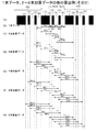
続いて、図5A〜Gを参照して、第1の実施例に係る1本データ、2本加算データの他の算出例(その1)について説明する。この例では、対象キャラクタC1の両側のキャラクタC0,C2まで加算範囲を拡張したものである。対象キャラクタC1と隣接する1つ前のキャラクタC0のスペース(6)及びバー(5)の2エレメントまで加算範囲を拡張し、1つ後ろのキャラクタC2のバー(1)及びスペース(2)の2エレメントまで加算範囲を拡張する場合を前提とする。 Next, with reference to FIGS. 5A to 5G, another calculation example (part 1) of the single data and the double added data according to the first embodiment will be described. In this example, the addition range is extended to the characters C0 and C2 on both sides of the target character C1. The addition range is expanded to the two elements of the space (6) and the bar (5) of the immediately preceding character C0 adjacent to the target character C1, and the bar (1) and the space (2) of the next character C2 are 2 It is assumed that the addition range is extended to the element.
図5Aに示す対象キャラクタC1の1つ前にはキャラクタC0が設けられ、対象キャラクタC1の1つ後ろにはキャラクタC2が設けられる。各々のキャラクタC0〜C2は、その各々が全幅11モジュールから構成される。3個のバー(1),(3),(5)及び3個のスペース(2),(4),(6)から構成される。バー(1)のモジュール数は「4」であり、バー(3),(5)のモジュール数は「1」である。また、スペース(2)のモジュール数は「1」であり、スペース(4),(6)のモジュール数は「2」である。これらのキャラクタC0〜C2を有したバーコードの場合を例に挙げて、対象キャラクタの作成する場合を説明する。 A character C0 is provided immediately before the target character C1 shown in FIG. 5A, and a character C2 is provided immediately after the target character C1. Each of the characters C0 to C2 is composed of 11 modules with a full width. It consists of three bars (1), (3), (5) and three spaces (2), (4), (6). The number of modules in bar (1) is “4”, and the number of modules in bars (3) and (5) is “1”. The number of modules in the space (2) is “1”, and the number of modules in the spaces (4) and (6) is “2”. Taking the case of a barcode having these characters C0 to C2 as an example, the case of creating a target character will be described.
図5Bに示す対象キャラクタC1のW11は、黒部分のバー(1)の幅である。バー(1)の幅はカウンタ部4により計数され、そのカウントデータ値が幅W11データを成す。W12は対象キャラクタC1のバー(1)に続くスペース(2)の幅である。スペース(2)の幅もカウンタ部4により計数され、そのカウントデータ値が幅W12データを成す。W13は対象キャラクタC1のスペース(2)に続くバー(3)の幅である。バー(3)の幅はカウンタ部4により計数され、そのカウントデータ値が幅W13データを成す。
W11 of the target character C1 shown in FIG. 5B is the width of the black part bar (1). The width of the bar (1) is counted by the
W14は対象キャラクタC1のバー(3)に続くスペース(4)の幅である。スペース(4)の幅もカウンタ部4により計数され、そのカウントデータ値が幅W14データを成す。W15は対象キャラクタC1のスペース(4)に続くバー(5)の幅である。バー(5)の幅はカウンタ部4により計数され、そのカウントデータ値が幅W15データを成す。W16は対象キャラクタC1のバー(5)に続くスペース(6)の幅である。スペース(6)の幅もカウンタ部4により計数され、そのカウントデータ値が幅W16データを成す。上述の6種類の幅W11データ〜幅W16データは1キャラクタの1本データであり、幅データD10を構成する。」
図5Cに示すW2-1は、1つ前の対象キャラクタC0のスペース(6)と対象キャラクタC1のバー(1)の各々が演算部23aによって加算された幅である。スペース(6)+バー(1)の加算幅を示すカウントデータ値が幅W2-1データを成す。W21は1つ前のキャラクタC0のスペース(6)に続く対象キャラクタC1のバー(1)とスペース(2)の各々が演算部23aによって加算された幅(以下バー(1)+スペース(2)と記す)である。バー(1)+スペース(2)の加算幅を示すカウントデータ値が幅W21データを成す。W22は対象キャラクタC1のバー(1)に続くスペース(2)及びバー(3)の各々が演算部23aによって加算された幅である。スペース(2)+バー(3)の加算幅を示すカウントデータ値が幅W22データを成す。
W14 is the width of the space (4) following the bar (3) of the target character C1. The width of the space (4) is also counted by the
W2-1 shown in FIG. 5C is a width obtained by adding the space (6) of the previous target character C0 and the bar (1) of the target character C1 by the
W23は対象キャラクタC1のスペース(2)に続くバー(3)及びスペース(4)の各々が演算部23aによって加算された幅である。バー(3)+スペース(4)の加算幅を示すカウントデータ値が幅W23データを成す。W24は対象キャラクタC1のバー(3)に続くスペース(4)及びバー(5)の各々が演算部23aによって加算された幅である。スペース(4)+バー(5)の加算幅を示すカウントデータ値が幅W24データを成す。
W23 is a width obtained by adding the bar (3) and the space (4) following the space (2) of the target character C1 by the
W25は対象キャラクタC1のスペース(4)に続くバー(5)及びスペース(6)の各々が演算部23aによって加算された幅である。バー(5)+スペース(6)の加算幅を示すカウントデータ値が幅W25データを成す。W26はバー(5)に続くスペース(6)及び1つ後ろのキャラクタC2のバー(1)の各々が演算部23aによって加算された幅である。スペース(6)+バー(1)の加算幅を示すカウントデータ値が幅W26データを成す。上述の7種類の幅W2-1データ〜幅W26データは1キャラクタの2本加算データであり、幅データD10を構成する。
W25 is a width obtained by adding the bar (5) and the space (6) following the space (4) of the target character C1 by the
図5Dに示すW3-2は、1つ前のキャラクタC0のバー(5)、スペース(6)及び、対象キャラクタC1のバー(1)の各々が演算部23aによって加算された幅である。バー(5)+スペース(6)+バー(1)の加算幅を示すカウントデータ値が幅W3-2データを成す。W3-1は、1つ前のキャラクタC0のスペース(6)、対象キャラクタC1のバー(1)及び、スペース(2)の各々が演算部23aによって加算された幅である。スペース(6)+バー(1)+スペース(2)の加算幅を示すカウントデータ値が幅W3-1データを成す。
W3-2 shown in FIG. 5D is a width obtained by adding the bar (5), the space (6) of the previous character C0, and the bar (1) of the target character C1 by the
W31は対象キャラクタC1のバー(1)、スペース(2)及びバー(3)の各々が演算部23aによって加算された幅である。バー(1)+スペース(2)+バー(3)の加算幅を示すカウントデータ値が幅W31データを成す。W32は対象キャラクタC1のバー(1)に続くスペース(2)、バー(3)及びスペース(4)の各々が演算部23aによって加算された幅である。スペース(2)+バー(3)+スペース(4)の加算幅を示すカウントデータ値が幅W32データを成す。
W31 is a width obtained by adding the bar (1), the space (2), and the bar (3) of the target character C1 by the
W33は対象キャラクタC1のスペース(2)に続くバー(3)、スペース(4)及びバー(5)の各々が演算部23aによって加算された幅である。バー(3)+スペース(4)+バー(5)の加算幅を示すカウントデータ値が幅W33データを成す。W34は対象キャラクタC1のバー(3)に続くスペース(4)、バー(5)及びスペース(6)の各々が演算部23aによって加算された幅である。スペース(4)+バー(5)+スペース(6)の加算幅を示すカウントデータ値が幅W34データを成す。
W33 is a width obtained by adding the bar (3), the space (4), and the bar (5) following the space (2) of the target character C1 by the
W35は、対象キャラクタC1のスペース(4)に続くバー(5)、スペース(6)、1つ後ろのキャラクタC2のバー(1)の各々が演算部23aによって加算された幅である。バー(5)+スペース(6)+バー(1)の加算幅を示すカウントデータ値が幅W35データを成す。W36は、対象キャラクタC1のバー(3)に続くスペース(6)の1つ後ろのキャラクタC2のバー(1)及びスペース(2)の各々が演算部23aによって加算された幅である。スペース(6)+バー(1)+スペース(2)の加算幅を示すカウントデータ値が幅W36データを成す。上述の8種類の幅W3-2データ〜幅W36データは1キャラクタの3本加算データであり、幅データD10を構成する。
W35 is a width obtained by adding the bar (5), the space (6) following the space (4) of the target character C1, and the bar (1) of the next character C2 by the
図5Eに示すW4-2は、1つ前のキャラクタC0のバー(5)、スペース(6)、対象キャラクタC1のバー(1)及びスペース(2)の各々が演算部23aによって加算された幅である。バー(5)+スペース(6)+バー(1)+スペース(2)の加算幅を示すカウントデータ値が幅W4-2データを成す。W4-1は、1つ前のキャラクタC0のスペース(6)、対象キャラクタC1のバー(1)、スペース(2)及びバー(3)の各々が演算部23aによって加算された幅である。スペース(6)+バー(1)+スペース(2)+バー(3)の加算幅を示すカウントデータ値が幅W4-1データを成す。
W4-2 shown in FIG. 5E is a width obtained by adding the bar (5), the space (6) of the previous character C0, the bar (1) and the space (2) of the target character C1 by the
W41は対象キャラクタC1のバー(1)、スペース(2)、バー(3)及びスペース(4)の各々が演算部23aによって加算された幅である。バー(1)+スペース(2)+バー(3)+スペース(4)の加算幅を示すカウントデータ値が幅W41データを成す。W42は対象キャラクタC1のバー(1)に続くスペース(2)、バー(3)、スペース(4)及びバー(5)の各々が演算部23aによって加算された幅である。スペース(2)+バー(3)+スペース(4)+バー(5)の加算幅を示すカウントデータ値が幅W42データを成す。
W41 is a width obtained by adding the bar (1), the space (2), the bar (3), and the space (4) of the target character C1 by the
W43は対象キャラクタC1のスペース(2)に続くバー(3)、スペース(4)、バー(5)及びスペース(6)の各々が演算部23aによって加算された幅である。バー(3)+スペース(4)+バー(5)+スペース(6)の加算幅を示すカウントデータ値が幅W43データを成す。W44は、対象キャラクタC1のバー(3)に続くスペース(4)、バー(5)、スペース(6)、1つ後ろのキャラクタC2のバー(1)の各々が演算部23aによって加算された幅である。スペース(4)+バー(5)+スペース(6)+バー(1)の加算幅を示すカウントデータ値が幅W44データを成す。
W43 is the width obtained by adding the bar (3), the space (4), the bar (5), and the space (6) following the space (2) of the target character C1 by the
W45は、対象キャラクタC1の白のスペース(4)に続くバー(5)、スペース(6)、1つ後ろのキャラクタC2のバー(1)及び、スペース(2)の幅である。バー(5)+スペース(6)+バー(1)+スペース(2)の加算幅を示すカウントデータ値が幅W45データを成す。上述の7種類の幅W4-2データ〜幅W45データは、1キャラクタの4本加算データであり、幅データD10を構成する。 W45 is the width of the bar (5), the space (6) following the white space (4) of the target character C1, the bar (1) of the next character C2, and the space (2). The counted data value indicating the added width of the bar (5) + the space (6) + the bar (1) + the space (2) forms the width W45 data. The above-mentioned seven types of width W4-2 data to width W45 data are 4-character addition data for one character, and form width data D10.
図5Fに示すW5-2は、1つ前のキャラクタC0のバー(5)、スペース(6)、対象キャラクタC1のバー(1)、スペース(2)及びバー(3)の各々が演算部23aによって加算された幅である。バー(5)+スペース(6)+バー(1)+スペース(2)+バー(3)の加算幅を示すカウントデータ値が幅W5-2データを成す。W5-1は、1つ前のキャラクタC0のスペース(6)+キャラクタC1のバー(1)+スペース(2)+バー(3)+スペース(4)の各々が演算部23aによって加算された幅である。スペース(6)+バー(1)+スペース(2)+バー(3)+スペース(4)の加算幅を示すカウントデータ値が幅W5-1データを成す。
W5-2 shown in FIG. 5F indicates that the bar (5), the space (6) of the previous character C0, the bar (1), the space (2), and the bar (3) of the target character C1 are each the
W51は対象キャラクタC1のバー(1)、スペース(2)、バー(3)、スペース(4)及びバー(5)の各々が演算部23aによって加算された幅である。バー(1)+スペース(2)+バー(3)+スペース(4)+バー(5)の加算幅を示すカウントデータ値が幅W51データを成す。W52は対象キャラクタC1のバー(1)に続くスペース(2)、バー(3)、スペース(4)、バー(5)及びスペース(6)の各々が演算部23aによって加算された幅である。スペース(2)+バー(3)+スペース(4)+バー(5)+スペース(6)の加算幅を示すカウントデータ値が幅W52データを成す。
W51 is a width obtained by adding the bar (1), space (2), bar (3), space (4), and bar (5) of the target character C1 by the
W53は、対象キャラクタC1のスペース(2)に続くバー(3)、スペース(4)、バー(5)、スペース(6)及び1つ後ろのキャラクタC2のバー(1)の各々が演算部23aによって加算された幅である。バー(3)+スペース(4)+バー(5)+スペース(6)+バー(1)の加算幅を示すカウントデータ値が幅W53データを成す。W54は、対象キャラクタC1のバー(3)に続くスペース(4)、バー(5)、スペース(6)、1つ後ろのキャラクタC2のバー(1)及びスペース(2)の各々が演算部23aによって加算された幅である。スペース(4)+バー(5)+スペース(6)+バー(1)+スペース(2)の加算幅を示すカウントデータ値が幅W54データを成す。上述の6種類の幅W5-2データ及び幅W54データは1キャラクタの5本加算データであり、幅データD10を構成する。
In W53, each of the bar (3), the space (4), the bar (5), the space (6), and the bar (1) of the next character C2 following the space (2) of the target character C1 is an
図5Gに示すW6-2は、1つ前のキャラクタC0のバー(5)、スペース(6)、対象キャラクタC1のバー(1)、スペース(2)、バー(3)及びスペース(4)の各々が演算部23aによって加算された幅である。バー(5)+スペース(6)+キャラクタC1のバー(1)+スペース(2)+バー(3)+スペース(4)の加算幅を示すカウントデータ値が幅W6-2データを成す。
W6-2 shown in FIG. 5G includes the bar (5), the space (6) of the previous character C0, the bar (1), the space (2), the bar (3), and the space (4) of the target character C1. Each is a width added by the
W6-1は、1つ前のキャラクタC0のスペース(6)、対象キャラクタC1のバー(1)、スペース(2)、バー(3)、スペース(4)及びバー(5)の各々が演算部23aによって加算された幅である。スペース(6)+バー(1)+スペース(2)+バー(3)+スペース(4)+バー(5)の加算幅を示すカウントデータ値が幅W6-1データを成す。 In W6-1, each of the space (6) of the previous character C0, the bar (1), the space (2), the bar (3), the space (4), and the bar (5) of the target character C1 is an arithmetic unit. The width added by 23a. The counted data value indicating the added width of the space (6) + bar (1) + space (2) + bar (3) + space (4) + bar (5) forms the width W6-1 data.
W61は対象キャラクタC1のバー(1)、スペース(2)、バー(3)、スペース(4)、バー(5)及びスペース(6)の各々が演算部23aによって加算された幅である。バー(1)+スペース(2)+バー(3)+スペース(4)+バー(5)+スペース(6)の加算幅を示すカウントデータ値が幅W61データを成す。
W61 is a width obtained by adding the bar (1), the space (2), the bar (3), the space (4), the bar (5), and the space (6) of the target character C1 by the
W62は対象キャラクタC1のバー(1)に続くスペース(2)、バー(3)、スペース(4)、バー(5)、スペース(6)及び1つ後ろのキャラクタC2のバー(1)の各々が演算部23aによって加算された幅である。スペース(2)+バー(3)+スペース(4)+バー(5)+スペース(6)+バー(1)の加算幅を示すカウントデータ値が幅W62データを成す。
W62 is a space (2), a bar (3), a space (4), a bar (5), a space (6), and a bar (1) of the next character C2 following the bar (1) of the target character C1. Is the width added by the
W63は対象キャラクタC1のスペース(2)に続くバー(3)、スペース(4)、バー(5)、スペース(6)、1つ後ろのキャラクタC2のバー(1)及びスペース(2)の各々が演算部23aによって加算された幅である。バー(3)+スペース(4)+バー(5)+スペース(6)+バー(1)+スペース(2)の加算幅を示すカウントデータ値が幅W63データを成す。上述の5種類の幅W6-2データ及び幅W63データは1キャラクタの6本加算データであり、幅データD10を構成する。
W63 is a bar (3), a space (4), a bar (5), a space (6), and a bar (1) and a space (2) of the character C2 that follows the space (2) of the target character C1. Is the width added by the
上述のカウンタ部4から出力されるカウントデータ値に基づいて、6種類の幅W11データ〜幅W16データ(1本データ)、7種類の幅W2-1データ〜幅W26データ(2本加算データ)、8種類の幅W3-2データ〜幅W36データ(3本加算データ)、7種類の幅W4-2データ〜幅W45データ(4本加算データ)、6種類の幅W5-2データ及び幅W54データ(5本加算データ)及び、5種類の幅W6-2データ及び幅W63データ(6本加算データ)の合計で、39種類の対象キャラクタが得られる。
Based on the count data value output from the
続いて、図6A〜Gを参照して、第1の実施例に係る1本データ、2本〜6本加算データの他の算出例(その2)について説明する。この例では、対象キャラクタC1の両側のキャラクタC0,C2まで加算範囲を拡張する場合であって、図6Aに示す対象キャラクタC1と隣接する1つ前のキャラクタC0のスペース(6)、バー(5)、スペース(4)、バー(3)及びスペース(2)の5エレメントまで加算範囲を拡張し、かつ、1つ後ろのキャラクタC2のバー(1)、スペース(2)、バー(3)、スペース(4)及びバー(5)の5エレメントまで加算範囲を拡張する場合を前提とする。これらのキャラクタC0〜C2を有したバーコード記号1の場合を例に挙げて、対象キャラクタを作成する場合を説明する。
Next, with reference to FIGS. 6A to 6G, another calculation example (part 2) of the single data and the two to six addition data according to the first embodiment will be described. In this example, the addition range is extended to the characters C0 and C2 on both sides of the target character C1, and the space (6) and bar (5) of the previous character C0 adjacent to the target character C1 shown in FIG. 6A are displayed. ), Space (4), bar (3) and space (2), and the range of addition is expanded to the next character C2 bar (1), space (2), bar (3), It is assumed that the addition range is extended to 5 elements of space (4) and bar (5). Taking the case of
図6Bに示すW11は対象キャラクタC1の黒部分のバー(1)の幅である。バー(1)の幅はカウンタ部4により計数され、そのカウントデータ値が幅W11データを成す。W12は対象キャラクタC1のバー(1)に続くスペース(2)の幅である。スペース(2)の幅もカウンタ部4により計数され、そのカウントデータ値が幅W12データを成す。W13はスペース(2)に続くバー(3)の幅である。バー(3)の幅はカウンタ部4により計数され、そのカウントデータ値が幅W13データを成す。
W11 shown in FIG. 6B is the width of the black bar (1) of the target character C1. The width of the bar (1) is counted by the
W14は対象キャラクタC1のバー(3)に続くスペース(4)の幅である。スペース(4)の幅もカウンタ部4により計数され、そのカウントデータ値が幅W14データを成す。W15は対象キャラクタC1のスペース(4)に続くバー(5)の幅である。バー(5)の幅はカウンタ部4により計数され、そのカウントデータ値が幅W15データを成す。W16は対象キャラクタC1のバー(5)に続くスペース(6)の幅である。スペース(6)の幅もカウンタ部4により計数され、そのカウントデータ値が幅W16データを成す。上述の6種類の幅W11データ〜幅W16データは1キャラクタの1本データであり、幅データD10を構成する。
W14 is the width of the space (4) following the bar (3) of the target character C1. The width of the space (4) is also counted by the
図6Cに示すW2-1は、1つ前のキャラクタC0のスペース(6)と対象キャラクタC1のバー(1)の各々が演算部23aによって加算された幅である。スペース(6)+バー(1)の加算幅を示すカウントデータ値が幅W2-1データを成す。W21は1つ前のキャラクタC0のスペース(6)に続くバー(1)とスペース(2)の各々が演算部23aによって加算された幅(以下バー(1)+スペース(2)と記す)である。バー(1)+スペース(2)の加算幅を示すカウントデータ値が幅W21データを成す。W22は対象キャラクタC1のバー(1)に続くスペース(2)及びバー(3)の各々が演算部23aによって加算された幅である。スペース(2)+バー(3)の加算幅を示すカウントデータ値が幅W22データを成す。
W2-1 shown in FIG. 6C is a width obtained by adding the space (6) of the previous character C0 and the bar (1) of the target character C1 by the
W23は対象キャラクタC1のスペース(2)に続くバー(3)及びスペース(4)の各々が演算部23aによって加算された幅である。バー(3)+スペース(4)の加算幅を示すカウントデータ値が幅W23データを成す。W24は対象キャラクタC1のバー(3)に続くスペース(4)及びバー(5)の各々が演算部23aによって加算された幅である。スペース(4)+バー(5)の加算幅を示すカウントデータ値が幅W24データを成す。W25は対象キャラクタC1のスペース(4)に続くバー(5)及びスペース(6)の各々が演算部23aによって加算された幅である。バー(5)+スペース(6)の加算幅を示すカウントデータ値が幅W25データを成す。W26は対象キャラクタC1のバー(5)に続くスペース(6)及び1つ後ろのキャラクタC2のバー(1)の各々が演算部23aによって加算された幅である。スペース(6)+バー(1)の加算幅を示すカウントデータ値が幅W26データを成す。上述の7種類の幅W2-1データ〜幅W26データは1キャラクタの2本加算データであり、幅データD10を構成する。
W23 is a width obtained by adding the bar (3) and the space (4) following the space (2) of the target character C1 by the
図6Dに示すW3-2は、1つ前のキャラクタC0のバー(5)、スペース(6)及び、対象キャラクタC1のバー(1)の各々が演算部23aによって加算された幅である。バー(5)+スペース(6)+バー(1)の加算幅を示すカウントデータ値が幅W3-2データを成す。W3-1は、1つ前のキャラクタC0のスペース(6)対象キャラクタC1のバー(1)及び、スペース(2)の各々が演算部23aによって加算された幅である。スペース(6)+バー(1)+スペース(2)の加算幅を示すカウントデータ値が幅W3-1データを成す。
W3-2 shown in FIG. 6D is a width obtained by adding the bar (5), the space (6) of the previous character C0, and the bar (1) of the target character C1 by the
W31は対象キャラクタC1のバー(1)、スペース(2)及びバー(3)の各々が演算部23aによって加算された幅である。バー(1)+スペース(2)+バー(3)の加算幅を示すカウントデータ値が幅W31データを成す。W32は対象キャラクタC1のバー(1)に続くスペース(2)、バー(3)及びスペース(4)の各々が演算部23aによって加算された幅である。スペース(2)+バー(3)+スペース(4)の加算幅を示すカウントデータ値が幅W32データを成す。
W31 is a width obtained by adding the bar (1), the space (2), and the bar (3) of the target character C1 by the
W33は対象キャラクタC1のスペース(2)に続くバー(3)、スペース(4)及びバー(5)の各々が演算部23aによって加算された幅である。バー(3)+スペース(4)+バー(5)の加算幅を示すカウントデータ値が幅W33データを成す。W34はバー(3)に続くスペース(4)、バー(5)及びスペース(6)の各々が演算部23aによって加算された幅である。スペース(4)+バー(5)+スペース(6)の加算幅を示すカウントデータ値が幅W34データを成す。
W33 is a width obtained by adding the bar (3), the space (4), and the bar (5) following the space (2) of the target character C1 by the
W35は、対象キャラクタC1のスペース(4)に続くバー(5)、スペース(6)、1つ後ろのキャラクタC2のバー(1)の各々が演算部23aによって加算された幅である。バー(5)+スペース(6)+バー(1)の加算幅を示すカウントデータ値が幅W35データを成す。W36は、対象キャラクタC1のバー(3)に続くスペース(6)の1つ後ろのキャラクタC2のバー(1)及びスペース(2)の各々が演算部23aによって加算された幅である。スペース(6)+バー(1)+スペース(2)の加算幅を示すカウントデータ値が幅W36データを成す。上述の8種類の幅W3-2データ〜幅W36データは1キャラクタの3本加算データであり、幅データD10を構成する。
W35 is a width obtained by adding the bar (5), the space (6) following the space (4) of the target character C1, and the bar (1) of the next character C2 by the
図6Eに示すW4-3は、1つ前のキャラクタC0のスペース(4)、バー(5)、スペース(6)及び、バー(1)の各々が演算部23aによって加算された幅である。スペース(4)+バー(5)+スペース(6)+バー(1)の加算幅を示すカウントデータ値が幅W4-3データを成す。W4-2は、1つ前のキャラクタC0のバー(5)、スペース(6)、対象キャラクタC1のバー(1)及びスペース(2)の各々が演算部23aによって加算された幅である。バー(5)+スペース(6)+バー(1)+スペース(2)の加算幅を示すカウントデータ値が幅W4-2データを成す。
W4-3 shown in FIG. 6E is a width obtained by adding the space (4), the bar (5), the space (6), and the bar (1) of the previous character C0 by the
W4-1は、1つ前のキャラクタC0のスペース(6)、対象キャラクタC1のバー(1)、スペース(2)及びバー(3)の各々が演算部23aによって加算された幅である。スペース(6)+バー(1)+スペース(2)+バー(3)の加算幅を示すカウントデータ値が幅W4-1データを成す。W41は対象キャラクタC1のバー(1)、スペース(2)、バー(3)及びスペース(4)の各々が演算部23aによって加算された幅である。バー(1)+スペース(2)+バー(3)+スペース(4)の加算幅を示すカウントデータ値が幅W41データを成す。W42は対象キャラクタC1のバー(1)に続くスペース(2)、バー(3)、スペース(4)及びバー(5)の各々が演算部23aによって加算された幅である。スペース(2)+バー(3)+スペース(4)+バー(5)の加算幅を示すカウントデータ値が幅W42データを成す。
W4-1 is a width obtained by adding the space (6) of the previous character C0, the bar (1), the space (2), and the bar (3) of the target character C1 by the
W43は対象キャラクタC1のスペース(2)に続くバー(3)、スペース(4)、バー(5)及びスペース(6)の各々が演算部23aによって加算された幅である。バー(3)+スペース(4)+バー(5)+スペース(6)の加算幅を示すカウントデータ値が幅W43データを成す。W44は、対象キャラクタC1のバー(3)に続くスペース(4)、バー(5)、スペース(6)、1つ後ろのキャラクタC2のバー(1)の各々が演算部23aによって加算された幅である。スペース(4)+バー(5)+スペース(6)+バー(1)の加算幅を示すカウントデータ値が幅W44データを成す。
W43 is the width obtained by adding the bar (3), the space (4), the bar (5), and the space (6) following the space (2) of the target character C1 by the
W45は、対象キャラクタC1の白のスペース(4)に続くバー(5)、スペース(6)、1つ後ろのキャラクタC2のバー(1)及び、スペース(2)の各々が演算部23aによって加算された幅である。バー(5)+スペース(6)+バー(1)+スペース(2)の加算幅を示すカウントデータ値が幅W45データを成す。W46は、対象キャラクタC1のバー(5)に続くスペース(6)、1つ後ろのキャラクタC2のバー(1)、スペース(2)及びバー(3)の各々が演算部23aによって加算された幅である。スペース(6)+バー(1)+スペース(2)+バー(3)の加算幅を示すカウントデータ値が幅W46データを成す。上述の9種類の幅W4-3データ〜幅W46データは1キャラクタの4本加算データであり、幅データD10を構成する。
In W45, the bar (5), the space (6) following the white space (4) of the target character C1, the bar (1) of the next character C2, and the space (2) are added by the
図6Fに示すW5-4は、1つ前のキャラクタC0のバー(3)、スペース(4)、バー(5)、スペース(6)+キャラクタC1のバー(1)の各々が演算部23aによって加算された幅である。バー(3)+スペース(4)+バー(5)+スペース(6)+バー(1)の加算幅を示すカウントデータ値が幅W5-4データを成す。W5-3は、1つ前のキャラクタC0のスペース(4)、バー(5)、スペース(6)、対象キャラクタC1のバー(1)及びスペース(2)の各々が演算部23aによって加算された幅である。スペース(4)+バー(5)+スペース(6)+バー(1)+スペース(2)の加算幅を示すカウントデータ値が幅W5-3データを成す。
W5-4 shown in FIG. 6F indicates that each of the bar (3), the space (4), the bar (5), the space (6) + the character C1 bar (1) of the previous character C0 is calculated by the
W5-2は、1つ前のキャラクタC0のバー(5)、スペース(6)、対象キャラクタC1のバー(1)、スペース(2)及びバー(3)の各々が演算部23aによって加算された幅である。バー(5)+スペース(6)+バー(1)+スペース(2)+バー(3)の加算幅を示すカウントデータ値が幅W5-2データを成す。W5-1は、1つ前のキャラクタC0のスペース(6)、対象キャラクタC1のバー(1)、スペース(2)、バー(3)及びスペース(4)の各々が演算部23aによって加算された幅である。スペース(6)+バー(1)+スペース(2)+バー(3)+スペース(4)の加算幅を示すカウントデータ値が幅W5-1データを成す。
In W5-2, the bar (5), the space (6) of the previous character C0, the bar (1), the space (2), and the bar (3) of the target character C1 are added by the
W51は対象キャラクタC1のバー(1)、スペース(2)、バー(3)、スペース(4)及びバー(5)の各々が演算部23aによって加算された幅である。バー(1)+スペース(2)+バー(3)+スペース(4)+バー(5)の加算幅を示すカウントデータ値が幅W51データを成す。W52は対象キャラクタC1のバー(1)に続くスペース(2)、バー(3)、スペース(4)、バー(5)及びスペース(6)の各々が演算部23aによって加算された幅である。スペース(2)+バー(3)+スペース(4)+バー(5)+スペース(6)の加算幅を示すカウントデータ値が幅W52データを成す。
W51 is a width obtained by adding the bar (1), space (2), bar (3), space (4), and bar (5) of the target character C1 by the
W53は、対象キャラクタC1のスペース(2)に続くバー(3)、スペース(4)、バー(5)、スペース(6)及び1つ後ろのキャラクタC2のバー(1)の各々が演算部23aによって加算された幅である。バー(3)+スペース(4)+バー(5)+スペース(6)+バー(1)の加算幅を示すカウントデータ値が幅W53データを成す。W54は、対象キャラクタC1のバー(3)に続くスペース(4)、バー(5)、スペース(6)、1つ後ろのキャラクタC2のバー(1)及びスペース(2)の各々が演算部23aによって加算された幅である。スペース(4)+バー(5)+スペース(6)+バー(1)+スペース(2)の加算幅を示すカウントデータ値が幅W54データを成す。
In W53, each of the bar (3), the space (4), the bar (5), the space (6), and the bar (1) of the next character C2 following the space (2) of the target character C1 is an
W55は、対象キャラクタC1のスペース(4)に続くバー(5)、スペース(6)、1つ後ろのキャラクタC2のバー(1)、スペース(2)及び、バー(3)の各々が演算部23aによって加算された幅である。バー(5)+スペース(6)+バー(1)+スペース(2)+バー(3)の加算幅を示すカウントデータ値が幅W55データを成す。W56は、対象キャラクタC1のバー(5)に続くスペース(6)、1つ後ろのキャラクタC2のバー(1)、スペース(2)、バー(3)及びスペース(4)の各々が演算部23aによって加算された幅である。スペース(6)+バー(1)+スペース(2)+バー(3)+スペース(4)の加算幅を示すカウントデータ値が幅W56データを成す。上述の10種類の幅W5-4データ及び幅W56データは1キャラクタの5本加算データであり、幅データD10を構成する。
In W55, the bar (5), the space (6) following the space (4) of the target character C1, the bar (1), the space (2), and the bar (3) of the next character C2 are each an arithmetic unit. The width added by 23a. The counted data value indicating the added width of the bar (5) + the space (6) + the bar (1) + the space (2) + the bar (3) forms the width W55 data. In W56, the space (6) following the bar (5) of the target character C1 and the bar (1), the space (2), the bar (3), and the space (4) of the next character C2 are calculated by the
図6Gに示すW6-5は、1つ前のキャラクタC0のスペース(2)、バー(3)、スペース(4)、バー(5)、スペース(6)及び、対象キャラクタC1のバー(1)の各々が演算部23aによって加算された幅である。スペース(2)+バー(3)+スペース(4)+バー(5)+スペース(6)+バー(1)の加算幅を示すカウントデータ値が幅W6-5データを成す。W6-4は、1つ前のキャラクタC0のバー(3)、スペース(4)、バー(5)、スペース(6)、対象キャラクタC1のバー(1)及びスペース(2)の各々が演算部23aによって加算された幅である。バー(3)+スペース(4)+バー(5)+スペース(6)+バー(1)+スペース(2)の加算幅を示すカウントデータ値が幅W6-4データを成す。
W6-5 shown in FIG. 6G is the space (2), bar (3), space (4), bar (5), space (6) of the previous character C0, and bar (1) of the target character C1. Are the widths added by the
W6-3は、1つ前のキャラクタC0のスペース(4)、バー(5)、スペース(6)、対象キャラクタC1のバー(1)、スペース(2)及びバー(3)の各々が演算部23aによって加算された幅である。スペース(4)+バー(5)+スペース(6)+バー(1)+スペース(2)+バー(3)の加算幅を示すカウントデータ値が幅W6-3データを成す。W6-2は、1つ前のキャラクタC0のバー(5)+スペース(6)+キャラクタC1のバー(1)+スペース(2)+バー(3)+スペース(4)の各々が演算部23aによって加算された幅である。バー(5)+スペース(6)+キャラクタC1のバー(1)+スペース(2)+バー(3)+スペース(4)の加算幅を示すカウントデータ値が幅W6-2データを成す。
In W6-3, the space (4), bar (5), space (6) of the previous character C0, the bar (1), the space (2) and the bar (3) of the target character C1 are each an arithmetic unit. The width added by 23a. The counted data value indicating the added width of space (4) + bar (5) + space (6) + bar (1) + space (2) + bar (3) forms the width W6-3 data. In W6-2, the bar (5) + space (6) of the previous character C0 + bar (1) + space (2) + bar (3) + space (4) of the character C1 is calculated by the
W6-1は、1つ前のキャラクタC0のスペース(6)+キャラクタC1のバー(1)+スペース(2)+バー(3)+スペース(4)+バー(5)の各々が演算部23aによって加算された幅である。スペース(6)+キャラクタC1のバー(1)+スペース(2)+バー(3)+スペース(4)+バー(5)の加算幅を示すカウントデータ値が幅W6-1データを成す。
In W6-1, the space (6) of the previous character C0 + the bar (1) of the character C1 + the space (2) + the bar (3) + the space (4) + the bar (5) is calculated by the
W61は対象キャラクタC1のバー(1)、スペース(2)、バー(3)、スペース(4)、バー(5)及びスペース(6)の各々が演算部23aによって加算された幅である。バー(1)+スペース(2)+バー(3)+スペース(4)+バー(5)+スペース(6)の加算幅を示すカウントデータ値が幅W61データを成す。
W61 is a width obtained by adding the bar (1), the space (2), the bar (3), the space (4), the bar (5), and the space (6) of the target character C1 by the
W62は対象キャラクタC1のバー(1)に続くスペース(2)、バー(3)、スペース(4)、バー(5)、スペース(6)及び、1つ後ろのキャラクタC2のバー(1)の各々が演算部23aによって加算された幅である。スペース(2)+バー(3)+スペース(4)+バー(5)+スペース(6)+バー(1)の加算幅を示すカウントデータ値が幅W62データを成す。
W62 is the space (2), bar (3), space (4), bar (5), space (6) following the bar (1) of the target character C1, and the bar (1) of the next character C2 Each is a width added by the
W63は対象キャラクタC1のスペース(2)に続くバー(3)、スペース(4)、バー(5)、スペース(6)、1つ後ろのキャラクタC2のバー(1)及びスペース(2)の各々が演算部23aによって加算された幅である。バー(3)+スペース(4)+バー(5)+スペース(6)+バー(1)+スペース(2)の加算幅を示すカウントデータ値が幅W63データを成す。
W63 is a bar (3), a space (4), a bar (5), a space (6), and a bar (1) and a space (2) of the character C2 that follows the space (2) of the target character C1. Is the width added by the
W64は、対象キャラクタC1のバー(3)に続くスペース(4)、バー(5)、スペース(6)、1つ後ろのキャラクタC2のバー(1)、スペース(2)及びバー(3)の各々が演算部23aによって加算された幅である。スペース(4)+バー(5)+スペース(6)+1つ後ろのキャラクタC2のバー(1)+スペース(2)+バー(3)の加算幅を示すカウントデータ値が幅W64データを成す。
W64 is the space (4), bar (5), space (6) following the bar (3) of the target character C1, and the bar (1), space (2), and bar (3) of the next character C2. Each is a width added by the
W65は、対象キャラクタC1のスペース(4)に続くバー(5)、スペース(6)、1つ後ろのキャラクタC2のバー(1)、スペース(2)、バー(3)及びスペース(4)の各々が演算部23aによって加算された幅である。バー(5)+スペース(6)+1つ後ろのキャラクタC2のバー(1)+スペース(2)+バー(3)+スペース(4)の加算幅を示すカウントデータ値が幅W65データを成す。
W65 includes the bar (5), the space (6) following the space (4) of the target character C1, the bar (1), the space (2), the bar (3) and the space (4) of the next character C2. Each is a width added by the
W66は、対象キャラクタC1のバー(5)に続くスペース(6)、1つ後ろのキャラクタC2のバー(1)、スペース(2)、バー(3)、スペース(4)及びバー(5)の各々が演算部23aによって加算された幅である。スペース(6)+1つ後ろのキャラクタC2のバー(1)+スペース(2)+バー(3)+スペース(4)+バー(5)の加算幅を示すカウントデータ値が幅W66データを成す。上述の11種類の幅W6-5データ及び幅W66データは1キャラクタの6本加算データであり、幅データD10を構成する。
W66 is the space (6) following the bar (5) of the target character C1, the bar (1), the space (2), the bar (3), the space (4) and the bar (5) of the next character C2. Each is a width added by the
この例では、図1に示したカウンタ部4から出力されるカウントデータ値に基づいて、6種類の幅W11データ〜幅W16データ(1本データ)、7種類の幅W2-1データ〜幅W26データ(2本加算データ)、8種類の幅W3-2データ〜幅W36データ(3本加算データ)、9種類の幅W4-3データ〜幅W46データ(4本加算データ)、10種類の幅W5-4データ及び幅W56データ(5本加算データ)及び、11種類の幅W6-5データ及び幅W66データ(6本加算データ)の合計で、51種類の対象キャラクタが得られる。
In this example, based on the count data value output from the
続いて、図7〜図10を参照して、第2の実施例に係るデコード例について説明する。ここで、図7A〜Cを参照して、CODE128のバーコード記号例、その欠損例及びその再構成例について説明をする。図7Aに示すCODE128のバーコード記号1は、バーやスペース等の欠落や傷等を生じていないものである。バーコード記号1は8キャラクタから構成され、例えば、バーコードデータD12は、数字の「123455678」を表現する。
Subsequently, a decoding example according to the second embodiment will be described with reference to FIGS. Here, with reference to FIGS. 7A to 7C, an example of a barcode symbol of CODE 128, a missing example thereof, and a reconfiguration example thereof will be described. The
図7Bに示すCODE128のバーコード記号1’は、バーやスペース等に欠落や傷等が生じているものである。バーコード記号1’は図7Aに示したCODE128のバーコード記号1に生じたものと仮定する。図中の3本の横向き破線は、閾値th1〜th3である。各々の閾値th1〜th3は、スキャン方向と直交する上・中・下段に設定されている。
A bar code symbol 1 'of CODE 128 shown in FIG. 7B is a bar, space, or the like that is missing or damaged. Assume that the bar code symbol 1 'occurs in the
閾値th1を基準にしてバーコード記号1’をスキャンして、データを読み込むと、傷等によりキャラクタ「3」及び「4」が欠落している。閾値th2を基準にしてバーコード記号1’をスキャンしてデータを読み込むと、傷等によりキャラクタ「3」〜「6」が欠落している。閾値th3を基準にしてバーコード記号1’をスキャンしてデータを読み込むと、傷等によりキャラクタ「7」及び「8」が欠落している。 When the bar code symbol 1 'is scanned with reference to the threshold th1 and data is read, the characters "3" and "4" are missing due to scratches or the like. When the bar code symbol 1 'is scanned with the threshold value th2 as a reference and data is read, the characters "3" to "6" are missing due to scratches or the like. When the bar code symbol 1 'is scanned with the threshold th3 as a reference and the data is read, the characters "7" and "8" are missing due to scratches or the like.
図7Cに示すように閾値th1を基準にしたデコード結果は、「12??5678」を示すバーコードデータD12が出力される。「3」及び「4」がデコードされていない。閾値th2を基準にしたデコード結果は、「12????78」を示すバーコードデータD12が出力される。「3」〜「6」がデコードされていない。閾値th3を基準にしたデコード結果は、「123456??」を示すバーコードデータD12が出力される。「7」及び「8」がデコードされていない。 As shown in FIG. 7C, the barcode data D12 indicating “12 ?? 5678” is output as the decoding result based on the threshold value th1. “3” and “4” are not decoded. As a decoding result based on the threshold value th2, bar code data D12 indicating “12 ??? 78” is output. “3” to “6” are not decoded. As a decoding result based on the threshold value th3, barcode data D12 indicating “123456 ??” is output. “7” and “8” are not decoded.
第2の実施例では、図7Bに示したようにバーやスペース等に欠落や傷等が生じている場合であっても、「12??5678」や、「12????78」、「123456??」等を「123455678」を表現するバーコードデータD12に再構成するようになされる。 In the second embodiment, as shown in FIG. 7B, even if a bar, space, or the like is missing or damaged, “12 ??? 5678”, “12 ?????? 78”, “123456 ??” and the like are reconstructed into barcode data D12 expressing “123455678”.
この例では、スキャン方向と直交する上・中・下段に次々とスキャンを行って、エラーキャラクタを補正し、エラーキャラクタが無くなった時点でCD(チェックデジット)の照合を行って、バーコードデータD12を作成するようにした。これにより、かすれ、汚れ等により、エレメントの一部が欠落しているバーコード記号1であってもその読み取りが可能となる。
In this example, scanning is performed one after another in the upper, middle, and lower stages orthogonal to the scanning direction, error characters are corrected, CD (check digit) verification is performed when there are no more error characters, and bar code data D12. Was created. Thereby, even the
また、第1の実施例では1キャラクタ内の幅データD10のみを利用した場合について説明したが、1キャラクタ内の端部の幅データD10が利用される回数が少ない。例えば、対象キャラクタC1のバー(1)の幅W11データは2本加算パターンの算出時、加算幅W21でのみ利用されるが、スペース(2)の幅W12データは、2本加算パターンの算出時、加算幅W21と加算幅W22とで利用されている。そこで、第2の実施例では当該キャラクタC1に隣接するキャラクタC0,C2も含めたエレメント部分も含めて計算を行うようにした。 In the first embodiment, the case where only the width data D10 within one character is used has been described. However, the number of times the width data D10 at the end within one character is used is small. For example, the width W11 data of the bar (1) of the target character C1 is used only in the addition width W21 when calculating the two-piece addition pattern, but the width W12 data of the space (2) is used when calculating the two-piece addition pattern. The addition width W21 and the addition width W22 are used. Therefore, in the second embodiment, the calculation is performed including the element portion including the characters C0 and C2 adjacent to the character C1.
続いて、図8〜図10を参照して、第2の実施例に係る難読キャラクタのデコード例(その1〜3)について説明する。この実施例では、パターン認識する加算範囲を両側の2キャラクタのエレメントまで拡張した。加算範囲は、図7Aに示した対象キャラクタと隣接する1つ前のキャラクタC0のスペース(6)、バー(5)、スペース(4)、バー(3)及びスペース(2)の5エレメントまで拡張し、かつ、1つ後ろのキャラクタC2のバー(1)、スペース(2)、バー(3)、スペース(4)及びバー(5)の5エレメントまで拡張する場合を前提とする。この加算範囲の拡張によって、51種類の対象キャラクタからデコード結果を得る場合を前提とする(マルチスキャンリコントラクション)
。
Subsequently, with reference to FIGS. 8 to 10, a decoding example (
.
これらをデコード条件にして、図8に示すフローチャートのステップST21でCPU23はスタートマージンを検索する。このとき、光学読取部2は、第1の実施例と同様にして、バーコード記号1を読み取って、コード読取データD2を発生する。コード読取データD2は、光学読取部2からカウンタ部4へ出力される。クロック発生部3は、所定周波数のサンプリングク用のCLK信号をカウンタ部4に出力する。
Using these as decoding conditions, the
カウンタ部4は光学読取部2から出力されるコード読取データD2を入力すると共に、クロック発生部3から出力されるCLK信号を入力し、CLK信号に基づいてコード読取データD2をカウントし、コード読取データD2を白部分のスペースおよび黒部分のバーを含むエレメントの1本幅及び2本加算幅を示すカウントデータD4に変換する。カウントデータD4は、バーコード記号1における各バー(黒部分)の幅およびスペース(白部分)の幅を示す数値データ列となる。カウントデータD4は、幅データ格納部10に保存される。なお、スタートマージンの検索については、その説明を省略する。
The
ステップST22でCPU23は、1キャラクタ分の幅データ(6本)を抽出する。図15に示したキャラクタC1によれば、黒部分のバー(1)の幅W11がカウンタ部4により計数され、そのカウントデータ値が幅W11データとなる。バー(1)に続く白部分のスペース(2)の幅W12もカウンタ部4により計数され、そのカウントデータ値が幅W12データとなる。スペース(2)に続くバー(3)の幅W13はカウンタ部4により計数され、そのカウントデータ値が幅W13データとなる。
In step ST22, the
このバー(3)に続くスペース(4)の幅W14もカウンタ部4により計数され、そのカウントデータ値は幅W14データとなる。スペース(4)に続くバー(5)の幅W15はカウンタ部4により計数され、そのカウントデータ値が幅W15データとなる。バー(5)に続くスペース(6)の幅W16もカウンタ部4により計数され、そのカウントデータ値が幅W16データとなる。上述の6種類の幅W11データ〜幅W16データはバーコードデータ値D30を構成する。バーコードデータ値D30はインターフェース部11を介してCPU23に出力される。
The
ステップST23でCPU23はバーの分割、消失の有無に基づいて制御を分岐する。バーの分割、消失の有無については、6本の幅の合計と1キャラクタ幅とを比較し、1キャラクタ分の幅データD10が適切かを判断する。ここでは、1キャラクタ内で隣接するバー及びスペースを含む6本のエレメントの幅を加算した合計値と、1キャラクタの全幅を示す全幅値とを比較し、比較結果に基づいて1キャラクタ分の幅データD10が適切か否かを判別する。
In step ST23, the
この例で、CPU23では比較部23cが1キャラクタ内で隣接する6本のバー(1)、スペース(2)、バー(3)、スペース(4)、バー(5)及びスペース(6)の幅W1〜W6の合計と、1キャラクタの全幅を示す全幅値とを比較する。比較部23cによる比較結果によって、1キャラクタ分の幅データD10が適切か否かが判別でき、この判別に基づいてキャラクタのバーの消失や分割等を判断できるようになる。また、複数のスキャンのデコード結果を組み合わせることが可能となり、汚れや、かすれがひどいバーコードにおいても読み取りが可能となる。
In this example, the
また、当該キャラクタC1の前後のキャラクタC0,C2の全幅からキャラクタフレームを判定できるので、ボイドやスポット等によるエレメントに過不足が有っても、デコードを継続できるようになる。また、バーの消失や分割等の判断結果に基づいて対象キャラクタを絞ることができ、計算量の軽減が図れ、処理時間の高速化につながる。 Further, since the character frame can be determined from the full widths of the characters C0 and C2 before and after the character C1, the decoding can be continued even if there are excess or deficiency in elements such as voids and spots. In addition, the target character can be narrowed down based on the determination result such as disappearance or division of the bar, the calculation amount can be reduced, and the processing time can be increased.
バーの分割、消失が無い場合は、ステップST24でCPU23は1モジュール幅を算出し、1キャラクタ幅を記憶する。このとき、演算部23aは、6種類の幅W11データ〜幅W16データに基づいて当該キャラクタC1の1モジュール幅を算出する。1キャラクタ幅は、図7Bに示した1キャラクタ内で隣接する6本のバー(1)、スペース(2)、バー(3)、スペース(4)、バー(5)及びスペース(6)の幅W1〜W6を合計して求められる。
If there is no division or disappearance of the bar, the
ステップST25でCPU23は1キャラクタ分の幅データD10を2本加算パターンに変換する。例えば、図7Cに示した1つ前のキャラクタC0のスペース(6)と対象キャラクタC1のバー(1)の各々が演算部23aによって加算された加算幅W2-1を示すカウントデータ値が幅W2-1データとなる。
In step ST25, the
同様にして、1つ前のキャラクタC0のスペース(6)に続くバー(1)とスペース(2)の各々が演算部23aによって加算された加算幅W21を示すカウントデータ値が幅W21データとなる。対象キャラクタC1のバー(1)に続くスペース(2)及びバー(3)の各々が演算部23aによって加算された加算幅W22を示すカウントデータ値が幅W22データとなる。
Similarly, the counted data value indicating the added width W21 obtained by adding the bar (1) and the space (2) following the space (6) of the previous character C0 by the
対象キャラクタC1のスペース(2)に続くバー(3)及びスペース(4)の各々が演算部23aによって加算された加算幅W23を示すカウントデータ値が幅W23データとなる。対象キャラクタC1のバー(3)に続くスペース(4)及びバー(5)の各々が演算部23aによって加算された加算幅W24を示すカウントデータ値が幅W24データとなる。
The counted data value indicating the added width W23 obtained by adding the bar (3) and the space (4) following the space (2) of the target character C1 by the
対象キャラクタC1のスペース(4)に続くバー(5)及びスペース(6)の各々が演算部23aによって加算された加算幅W25を示すカウントデータ値が幅W25データとなる。対象キャラクタC1のバー(3)に続くスペース(4)及び1つ後ろのキャラクタC2のバー(1)の各々が演算部23aによって加算された加算幅W26を示すカウントデータ値が幅W26データとなる。上述の7種類の幅W2-1データ〜幅W26データは1キャラクタの2本加算データであり、幅データD10から構成される。
The counted data value indicating the added width W25 obtained by adding the bar (5) and the space (6) following the space (4) of the target character C1 by the
その後、ステップST26でCPU23は、先に変換した2本加算パターンが一致するキャラクタを検索する。この例では、図1に示したカウンタ部4から出力されるカウントデータ値に基づいて、検索部23dが、6種類の幅W11データ〜幅W16データ(1本データ)、7種類の幅W2-1データ〜幅W26データ(2本加算データ)、8種類の幅W3-2データ〜幅W36データ(3本加算データ)、9種類の幅W4-3データ〜幅W46データ(4本加算データ)、10種類の幅W5-4データ及び幅W56データ(5本加算データ)及び、11種類の幅W6-5データ及び幅W66データ(6本加算データ)の51種類の対象キャラクタC1に対して一致するキャラクタを検索する。その際に各エレメントの幅に対して2種類の対象キャラクタのどちらかと一致する対象キャラクタを検索し、対象キャラクタを絞り込む。この絞り込みにより、おおよそ1〜4程度の候補キャラクタが検索される。
Thereafter, in step ST26, the
ステップST27でCPU23は一致するキャラクタの存在有無に基づいて制御を分岐する。一致するキャラクタが存在する場合は、ステップST28で2本加算パターンが一致した対象キャラクタをデコード結果とする。その後、図9に示すステップST31に移行する。
In step ST27, the
なお、ステップST23でバーの分割、消失が有る場合、及び、ステップST27で一致するキャラクタが存在しない場合は、ステップST29でCPU23は現在のキャラクタをエラーキャラクタとする。その後、ステップST30でCPU23は次のキャラクタ(1キャラクタ幅分後ろのデータ)のデコード処理に移行する。その後、ステップST22に移行して、上述した内容を繰り返す。
If there is a division or disappearance of bars in step ST23, and if there is no matching character in step ST27, the
上述のステップST28でデコード結果となされた候補キャラクタについては、図9に示すステップST31でCPU23はマージン直後のキャラクタか否かに基づいて制御を分岐する。デコード結果となされた候補キャラクタが、マージン直後のキャラクタではない場合は、ステップST32に移行してCPU23はデコード結果がストップキャラクタか否かに基づいて制御を分岐する。デコード結果がストップキャラクタである場合は、ステップST33に移行してCPU23は、デコード結果にエラーキャラクタが存在しないか否かに基づいて制御を分岐する。
For the candidate character that is the decoding result in step ST28 described above, in step ST31 shown in FIG. 9, the
デコード結果にエラーキャラクタが存在しない場合は、ステップST34に移行して、CPU23はデコードバッファ25に現在(今)のスキャンのデコード結果を上書きする。その後、ステップST35に移行してCPU23は誤り検知(パリティチェック)を実行して、チェックデジットが正しいか否かに基づいて制御を分岐する。チェックデジットが正しい場合は、ステップST36でCPU23は読み取りを完了し、デコードバッファ25のバーコードデータD12を出力し、デコードバッファ25をクリアする(正常終了)。その後、ステップST45に移行する。
When there is no error character in the decoding result, the process proceeds to step ST34, and the
なお、ステップST31でマージン直後のキャラクタである場合は、ステップST37に移行してCPU23は、デコード結果がスタートキャラクタか否かに基づいて制御を分岐する。上述のステップST37でデコード結果がスタートキャラクタでない場合及び、ステップST32でデコード結果がストップキャラクタでない場合は、ステップST38に移行する。ステップST38でCPU23は、次キャラクタ(6本後ろの幅データD10)のデコード処理を実行する。その後、ステップST22に戻る。
If the character is immediately after the margin in step ST31, the process proceeds to step ST37, and the
また、ステップST33でデコード結果にエラーキャラクタが存在している場合は、図10に示すステップST39でCPU23はデコードバッファ25の長さとデコードデータ長とが等しいか否かに基づいて制御を分岐する。デコードバッファ25の長さとデコードデータ長とが等しい場合は、ステップST41で、デコードバッファ25のエラーキャラクタ部分のデコードが成功していたらデータを書き換える。その後、ステップST42に移行して、デコードバッファ25にエラーキャラクタが存在しない否かに基づいて制御を分岐する。デコードバッファ25にエラーキャラクタが存在していない場合は、ステップST35に戻る。
If an error character is present in the decoding result in step ST33, the
上述のステップST35でチェックデジットが誤っている場合は、図10に示すステップST43でデコードバッファ25をクリアした後、図9に示したステップST37でデコード結果がスタートキャラクタではない場合、図10に示したステップST39でデコードバッファ25の長さとデコードデータ長とが異なる場合は、ステップST40でデコードバッファ25をクリアした後、及び、ステップST42でデコードバッファ25にエラーキャラクタが存在する場合は、ステップST44に移行してCPU23は、読み取りエラー処理を実行する。読み取りエラー処理では次のマージンを検索する等が行われる。
If the check digit is incorrect in step ST35 described above, the
また、キャラクタ認識がエラーとなった場合に、エラーキャラクタを仮に配置してバーコードデータを作成するようにしてもよい。その後、図9に示すステップST45に移行して、CPU23は終了を判別する。例えば、当該バーコード記号読取装置100に対して読取終了指令が検出され、読取終了指令が検出された場合は、バーコード記号1の読み取り制御を終了する。読取終了指令が検出されていない場合は、バーコード記号1の読み取り制御を継続するべく、ステップST21に戻って、上述した内容を繰り返すようになされる。
Further, when character recognition results in an error, barcode data may be created by temporarily placing an error character. Thereafter, the process proceeds to step ST45 shown in FIG. 9, and the
このように第2の実施例に係るバーコード記号読取装置100によれば、パターン認識する加算範囲を対象キャラクタの両側の2キャラクタC0,C2のエレメントまで拡張した。すなわち、加算範囲に関して、図7Aに示した対象キャラクタと隣接する1つ前のキャラクタC0のスペース(6)、バー(5)、スペース(4)、バー(3)及びスペース(2)の5エレメントまで拡張し、かつ、1つ後ろのキャラクタC2のバー(1)、スペース(2)、バー(3)、スペース(4)及びバー(5)の5エレメントまで拡張したので、51種類の対象キャラクタの中からデコード結果となる候補キャラクタを決定できるようになる。
As described above, according to the
従って、キャラクタ内の幅データだけでパターン認識を行う従来方式に比べて、対象キャラクタの両側の2キャラクタC0,C2のエレメントも含めた部分についても計算に参画されるので、対象キャラクタの端部に、欠落、傷等の誤差が多く含まれるパターンであっても、誤読し難くなった。これにより、バー、スペース等のエレメント(エレメント)の幅の最大誤差が±0.5モジュール以上あっても、キャラクタとして認識できる可能性が高くなった。しかも、対象キャラクタを絞ることによって、計算量の軽減が図れ、パターン認識処理に係る時間が短縮され、データ処理の高速化につながる。 Therefore, as compared with the conventional method in which pattern recognition is performed only with the width data in the character, the part including the elements of the two characters C0 and C2 on both sides of the target character is also included in the calculation, so Even patterns with many errors such as missing or scratches are difficult to misread. As a result, even when the maximum width error of elements such as bars and spaces is ± 0.5 modules or more, the possibility of being recognized as a character is increased. In addition, by narrowing down the target characters, the amount of calculation can be reduced, the time required for the pattern recognition processing is shortened, and the data processing speed is increased.
続いて、図11〜図13を参照して、第3の実施例に係る難読キャラクタのデコード例(その1〜3)について説明する。この実施例では、第1の実施例で説明したキャラクタデコードアルゴリズムと、第2の実施例で説明したマルチスキャンリコントラクションとを併合した処理が行われる。これらをデコード条件にして、図11に示すフローチャートのステップST51でスタートマージンを検索する。このとき、光学読取部2は、第1の実施例と同様にして、バーコード記号1を読み取って、コード読取データD2を発生する。コード読取データD2は、光学読取部2からカウンタ部4へ出力される。クロック発生部3は、所定周波数のサンプリングク用のCLK信号をカウンタ部4に出力する。
Subsequently, with reference to FIGS. 11 to 13, a decoding example (
カウンタ部4は光学読取部2から出力されるコード読取データD2を入力すると共に、クロック発生部3から出力されるCLK信号を入力し、CLK信号に基づいてコード読取データD2をカウントし、コード読取データD2を白部分のスペースおよび黒部分のバーを含むエレメントの1本幅及び2本加算幅を示すカウントデータD4に変換する。カウントデータD4は、バーコード記号1における各バー(黒部分)の幅およびスペース(白部分)の幅を示す数値データ列となる。カウントデータD4は、幅データ格納部10に保存される。なお、スタートマージンの検索については、その説明を省略する。
The
ステップST52でCPU23は6本の幅の合計と1キャラクタ幅とを比較し、1キャラクタ分の幅データD10が適切かを判断する。ここでは、1キャラクタ内で隣接するバー及びスペースを含む6本のエレメントの幅を加算した合計値と、1キャラクタの全幅を示す全幅値とを比較し、比較結果に基づいて1キャラクタ分の幅データD10が適切か否かを判別する。
In step ST52, the
この例で、CPU23では比較部23cが1キャラクタ内で隣接する6本のバー(1)、スペース(2)、バー(3)、スペース(4)、バー(5)及びスペース(6)の幅W1〜W6の合計と、1キャラクタの全幅を示す全幅値とを比較する。比較部23cによる比較結果によって、1キャラクタ分の幅データD10が適切か否かが判別でき、この判別に基づいてキャラクタ候補を絞ることができ、計算量の軽減が図れ、処理時間の高速化につながる。
In this example, the
ステップST53でCPU23はバーの分割、消失の有無に基づいて制御を分岐する。バーの分割、消失の有無については、比較部23cによる比較結果を利用する。対象キャラクタC1の前後のキャラクタC0,C2の全幅からキャラクタフレームを判定できるので、ボイドやスポット等によるエレメントに過不足が有っても、デコードを継続できるようになる。
In step ST53, the
バーの分割、消失が無い場合は、ステップST54でCPU23は1モジュール幅を算出し、1キャラクタ幅を記憶する。このとき、演算部23aは、6種類の幅W11データ〜幅W16データに基づいて対象キャラクタC1の1モジュール幅を算出する。1キャラクタ幅は、図7Bに示した1キャラクタ内で隣接する6本のバー(1)、スペース(2)、バー(3)、スペース(4)、バー(5)及びスペース(6)の幅W1〜W6を合計して求められる。
If there is no division or disappearance of the bar, the
ステップST55でCPU23は抽出された21種類の幅データD10を1〜6本加算パターン(エレメント幅)に変換する。この例では、6種類の幅W11データ〜幅W16データが1キャラクタの1本データに変換され、1本データに基づく対象キャラクタC1の被認識パターンとして、1本パターンが作成される。5種類の幅W21データ〜幅W25データは1キャラクタの2本加算データに変換され、2本加算データに基づく対象キャラクタC1の2本加算パターン(被認識パターン)が作成される。4種類の幅W31データ〜幅W34データは1キャラクタの3本加算データに変換され、3本加算データに基づく対象キャラクタC1の3本加算識パターンが作成される。
3種類の幅W41データ〜幅W43データは1キャラクタの4本加算データに変換され、4本加算データに基づく対象キャラクタC1の4本加算パターンが作成される。2種類の幅W51データ及び幅W52データは1キャラクタの5本加算データに変換され、5本加算データに基づく対象キャラクタの5本加算パターンが作成される。1種類の幅W61データは1キャラクタの6本加算データに変換され、6本加算データに基づく対象キャラクタC4の6本加算パターンが作成される。
In step ST55, the
The three types of width W41 data to width W43 data are converted into four character addition data for one character, and a four character addition pattern for the target character C1 based on the four character addition data is created. The two types of width W51 data and width W52 data are converted into 5-character addition data for one character, and a 5-character addition pattern for the target character is created based on the 5-addition data. One type of width W61 data is converted into six character addition data of one character, and a six character addition pattern of the target character C4 based on the six character addition data is created.
ステップST56でCPU23はキャラクタを絞り込むために、1本パターン、2〜6本加算パターンの全てに対してモジュール数の誤差が1以内のキャラクタを検索して候補キャラクタを決定する。このとき、CPU23では抽出部23bが、演算部23aによって求められた1本パターン、2〜6本加算パターンの各々のモジュール数が誤差1以内の整数となる対象キャラクタC1等を絞り込んで候補キャラクタを抽出する。その際に、抽出部23bは、演算部23aによって求められた1本パターン、2〜6本加算パターンの1キャラクタ分の6本の幅データD10と、対象キャラクタの前後の(6−1)本の幅データD10とを抽出する。
In step ST56, in order to narrow down the characters, the
ステップST57でCPU23は、候補キャラクタが1つ以上存在するか否かに基づいて制御を分岐する。候補キャラクタが1つ以上(複数)存在する場合は、ステップST58で1〜6本加算パターンの実測値とその理想値との間の誤差を算出し、この誤差の合計が最小となった候補キャラクタをデコード結果とする。この誤差値が最小となる候補キャラクタは、期待値キャラクタと最も相関が強いキャラクタである。この例では、総合的な誤差が最も少ない対象キャラクタC1等を候補キャラクタとして選択できるようになる。
In step ST57, the
このとき、CPU23では、期待値キャラクタ(理論値)が期待値格納部24からCPU23の比較部23cへ読み出される。比較部23cは、抽出部23bによって抽出された各々の2〜6本加算パターン(エレメント幅)のモジュール数の候補キャラクタと、候補キャラクタを評価するための期待値キャラクタ(理論値)とを比較する。この比較結果は検索部23dへ出力される。
At this time, the
検索部23dでは、候補キャラクタと最も相関が強い期待値キャラクタが検索される。例えば、上述の演算部23aが候補キャラクタのモジール数の実測値と、期待値キャラクタのモジール数の理想値との間の誤差を算出すると、検索部23dが、演算部23aによって算出された誤差を合計して得られる誤差値が最小となる候補キャラクタと最も相関が強い期待値キャラクタを検索する。
The search unit 23d searches for an expected value character having the strongest correlation with the candidate character. For example, when the
この例では、誤差値が最小となる候補キャラクタと最も相関が強い期待値キャラクタを検索するので、従来方式のバーコード読み取り方法に比べて大幅にバーコードの誤読取を防止できるようになる。なお、ステップST57で候補キャラクタが存在しない場合は、ステップST59で現在のキャラクタをエラーキャラクタとする。その後、ステップST60で次のキャラクタ(キャラクタ幅分後ろのデータ)のデコード処理に移行する。 In this example, since the expected value character having the strongest correlation with the candidate character having the smallest error value is searched, it is possible to prevent erroneous barcode reading significantly compared to the conventional barcode reading method. If no candidate character exists in step ST57, the current character is set as an error character in step ST59. Thereafter, in step ST60, the process proceeds to a decoding process for the next character (data after the character width).
上述のステップST58でデコード結果となされた候補キャラクタについては、図12に示すステップST61でCPU23はマージン直後の対象キャラクタか否かに基づいて制御を分岐する。デコード結果となされた候補キャラクタが、マージン直後の対象キャラクタではない場合は、ステップST62に移行してCPU23はデコード結果がストップキャラクタか否かに基づいて制御を分岐する。デコード結果がストップキャラクタである場合は、ステップST63に移行してCPU23は、デコード結果にエラーキャラクタが存在しないか否かに基づいて制御を分岐する。
For the candidate character obtained as a result of decoding in step ST58 described above, in step ST61 shown in FIG. 12, the
デコード結果にエラーキャラクタが存在しない場合は、ステップST64に移行して、CPU23はデコードバッファ25に現在(今)のスキャンのデコード結果を上書きする。その後、ステップST65に移行してCPU23は誤り検知(パリティチェック)を実行して、チェックデジットが正しいか否かに基づいて制御を分岐する。チェックデジットが正しい場合は、ステップST66でCPU23は読み取りを完了し、デコードバッファ25のバーコードデータD12を出力し、デコードバッファ25をクリアする(正常終了)。その後、ステップST65に移行する。
If there is no error character in the decoding result, the process proceeds to step ST64, and the
なお、ステップST61でマージン直後の対象キャラクタである場合は、ステップST67に移行してCPU23は、デコード結果がスタートキャラクタか否かに基づいて制御を分岐する。上述のステップST67でデコード結果がスタートキャラクタである場合及び、ステップST62でデコード結果がストップキャラクタである場合は、ステップST68に移行する。ステップST68でCPU23は、次キャラクタ(6本後ろの幅データD10)のデコード処理を実行する。その後、ステップST52に戻る。
If the target character is immediately after the margin in step ST61, the process proceeds to step ST67, and the
また、ステップST63でデコード結果にエラーキャラクタが存在している場合は、図13に示すステップST69でCPU23はデコードバッファ25の長さとデコードデータ長とが等しいか否かに基づいて制御を分岐する。デコードバッファ25の長さとデコードデータ長とが等しい場合は、ステップST71で、デコードバッファ25のエラーキャラクタ部分のデコードが成功していたらデータを書き換える。その後、ステップST72に移行して、デコードバッファ25にエラーキャラクタが存在しない否かに基づいて制御を分岐する。デコードバッファ25にエラーキャラクタが存在していない場合は、ステップST65に戻る。
If there is an error character in the decoding result in step ST63, the
上述のステップST65でチェックデジットが誤っている場合は、図13に示すステップST73でデコードバッファ25をクリアした後、図12に示したステップST67でデコード結果がスタートキャラクタではない場合、図13に示したステップST69でデコードバッファ25の長さとデコードデータ長とが異なる場合は、ステップST70でデコードバッファ25をクリアした後、及び、ステップST72でデコードバッファ25にエラーキャラクタが存在する場合は、ステップST74に移行してCPU23は、読み取りエラー処理を実行する。読み取りエラー処理では次のマージンを検索する等が行われる。
If the check digit is incorrect in step ST65 described above, the
また、キャラクタ認識がエラーとなった場合に、エラーキャラクタを仮に配置してバーコードデータを作成するようにしてもよい。その後、図12に示すステップST75に移行して、CPU23は終了を判別する。例えば、当該バーコード記号読取装置100に対して読取終了指令が検出され、読取終了指令が検出された場合は、バーコード記号1の読み取り制御を終了する。読取終了指令が検出されていない場合は、バーコード記号1の読み取り制御を継続するべく、ステップST51に戻って、上述した内容を繰り返すようになされる。
Further, when character recognition results in an error, barcode data may be created by temporarily placing an error character. Thereafter, the process proceeds to step ST75 shown in FIG. 12, and the
このように、第3の実施例に係るバーコード記号読取装置100によれば、バーコード記号1を読み取ってそのデコード結果を出力する場合に、第1の実施例で説明したキャラクタデコードアルゴリズムと、第2の実施例で説明したマルチスキャンリコントラクションとを併合した処理が行われる。これを前提にして、検索部23dが抽出部23bによって抽出された各々の2〜6本加算パターンのモジュール数の候補キャラクタと、当該候補キャラクタを評価するための期待値キャラクタとを比較し、当該候補キャラクタと最も相関が強い期待値キャラクタを検索するようになる。
Thus, according to the
この検索によって、複数の対象キャラクタから抽出された候補キャラクタと最も相関が強い期待値キャラクタのバーコードデータD12を当該バーコード記号1の読取時のデコード結果として出力できるようになるので、従来方式のバーコード読み取り方法に比べて大幅にバーコード記号1の誤読取を防止できるようになる。
By this search, the barcode data D12 of the expected value character having the strongest correlation with the candidate character extracted from the plurality of target characters can be output as the decoding result when the
しかも、誤差の範囲を従来方式の±0.5から±1.0に拡大し、対象キャラクタを増加させている。そして、1キャラクタ分の6本の幅データD10と、対象キャラクタの前後の5本の幅データD10とを抽出するので、2〜6本加算パターンの各々のモジュール数が誤差1以内の整数となる対象キャラクタを絞り込んだ候補キャラクタを従来方法に比べてより多く抽出できるようになる。また、候補キャラクタを絞ることによって、計算量の軽減が図れ、パターン認識処理に係る時間が短縮され、データ処理の高速化につながる。これにより、従来方式のバーコード読み取り方法に比べて大幅にバーコードの誤読取を防止できるようになる。なお、誤差の範囲を設定する際の閾値を可変することで、幅データD10の信頼性を選択することも可能となる。 In addition, the range of error is expanded from ± 0.5 of the conventional method to ± 1.0 to increase the target character. Since 6 width data D10 for one character and 5 width data D10 before and after the target character are extracted, the number of modules in each of the 2 to 6 addition patterns becomes an integer within an error of 1. More candidate characters can be extracted by narrowing down the target characters compared to the conventional method. In addition, by narrowing down the candidate characters, the amount of calculation can be reduced, the time required for the pattern recognition processing is shortened, and the data processing speed is increased. As a result, it is possible to largely prevent erroneous barcode reading as compared with the conventional barcode reading method. Note that the reliability of the width data D10 can be selected by changing the threshold value when setting the error range.
この例では、バーコード記号の規格に関して、CODE128の場合について説明したが、これに限られることはなく、CODE39、EAN/UPC、インターリーブド2オブ5、コーダバー、RSS、RSSリミテッド、RSSエクスパンデド等の各々の方式についても、本発明を同様にして適用できるようになる。 In this example, the case of CODE128 has been described with respect to the bar code symbol standard, but it is not limited to this, and CODE39, EAN / UPC, interleaved 2 of 5, coder bar, RSS, RSS Limited, RSS expanded, etc. The present invention can be similarly applied to each method.
本発明は、バーコード記号を読み取ってバーコードデータを出力するバーコード記号読取装置に適用して極めて好適である。 The present invention is very suitable when applied to a bar code symbol reading device that reads bar code symbols and outputs bar code data.
2・・・光学情報読取部、3・・・クロック発生部、4・・・カウンタ部、5・・・m段データバッファ、6・・・セレクタ部、7・・・x倍器、8・・・比較器、・・・スタートマージン格納部、10・・・幅データ格納部、11・・・インターフェース部、
12・・・マイクロプロセッサ、21・・・ROM、22・・・RAM、23・・・CPU、23a・・・演算部(演算手段)、23b・・・抽出部(抽出手段)、23c・・・比較部、23d・・・検索部、24・・・期待値格納部、25・・・デコードバッファ及び、100・・・バーコード記号読取装置(光学情報読取装置)
2 ... optical information reading unit, 3 ... clock generation unit, 4 ... counter unit, 5 ... m-stage data buffer, 6 ... selector unit, 7 ... x multiplier, ..Comparator, ... start margin storage unit, 10 ... width data storage unit, 11 ... interface unit,
12 ... Microprocessor, 21 ... ROM, 22 ... RAM, 23 ... CPU, 23a ... Calculation unit (calculation unit), 23b ... Extraction unit (extraction unit), 23c. Comparison unit, 23d ... search unit, 24 ... expected value storage unit, 25 ... decode buffer, and 100 ... bar code symbol reader (optical information reader)
Claims (16)
前記演算手段によって求められた前記2〜n本加算エレメント幅の各々のモジュール数が誤差1以内の整数となる対象キャラクタを絞り込んで候補キャラクタを抽出する抽出手段と、
前記抽出手段によって抽出された各々の前記2〜n本加算エレメント幅のモジュール数の候補キャラクタと、当該候補キャラクタを評価するための期待値キャラクタとを比較し、当該候補キャラクタと最も相関が強い期待値キャラクタを検索する検索手段とを備えることを特徴とする光学情報読取装置。 The width of n (n ≧ 2) elements including adjacent bars and spaces in one character is added to obtain 2 to n added element widths, and each of the 2 to n added element widths is determined to be one character. A calculation means for obtaining the number of modules of the 2-n addition element width in terms of the number of modules;
Extraction means for extracting candidate characters by narrowing down target characters in which the number of modules of each of the 2 to n addition element widths obtained by the calculation means is an integer within an error of 1;
Compare each of the 2 to n candidate element width candidate characters extracted by the extracting means with an expected value character for evaluating the candidate character, and expect the strongest correlation with the candidate character. An optical information reading apparatus comprising: search means for searching for a value character.
当該対象キャラクタの前記2〜n本加算エレメント幅を各々求める際に、
前記対象キャラクタの前後のキャラクタのバー及びスペースを含むエレメントの幅を加算することを特徴とする請求項1に記載の光学情報読取装置。 The computing means is
When obtaining each of the 2 to n additional element widths of the target character,
The optical information reader according to claim 1, wherein widths of elements including bars and spaces of characters before and after the target character are added.
当該対象キャラクタの前記2〜n本加算エレメント幅を各々求める際に、
前記1キャラクタ分のn本の幅データと、当該対象キャラクタの前後の1本以上の幅データとを抽出することを特徴とする請求項1に記載の光学情報読取装置。 The extraction means includes
When obtaining each of the 2 to n additional element widths of the target character,
2. The optical information reader according to claim 1, wherein n width data for the one character and one or more width data before and after the target character are extracted.
前記抽出手段から得られた複数の前記対象キャラクタの各々の前記2〜n本加算エレメント幅に対して2種類の前記対象キャラクタの何れかと一致する対象キャラクタを検索し、前記候補キャラクタの数を絞り込むことを特徴とする請求項1に記載の光学情報読取装置。 The search means includes
Search for target characters that match one of the two types of target characters with respect to the 2 to n additional element widths of each of the plurality of target characters obtained from the extracting means, and narrow down the number of candidate characters. The optical information reader according to claim 1.
前記候補キャラクタのモジール数の実測値と、前記期待値キャラクタのモジール数の理想値との間の誤差を算出し、前記誤差を合計して得られる誤差値が最小となる前記候補キャラクタと最も相関が強い期待値キャラクタを検索することを特徴とする請求項1に記載の光学情報読取装置。 The search means includes
An error between the measured value of the number of modules of the candidate character and the ideal value of the number of modules of the expected value character is calculated, and the error value obtained by summing up the errors is most correlated with the candidate character. The optical information reading apparatus according to claim 1, wherein an expected value character having a high is searched.
前記誤差値が最小となる前記候補キャラクタと一致する前記期待値キャラクタを検出することを特徴とする請求項5に記載の光学情報読取装置。 The search means includes
6. The optical information reading apparatus according to claim 5, wherein the expected value character that matches the candidate character having the smallest error value is detected.
1キャラクタ内で隣接するバー及びスペースを含むn(n≧2)本のエレメントの幅を加算して2〜n本加算エレメント幅を各々求めるステップと、
求めた前記2〜n本加算エレメント幅の各々を1キャラクタのモジュール数に換算して当該2〜n本加算エレメント幅のモジュール数を求めるステップと、
求めた前記2〜n本加算エレメント幅の各々のモジュール数が誤差1以内の整数となる対象キャラクタを絞り込んで候補キャラクタを抽出するステップと、
抽出された各々の前記2〜n本加算エレメント幅のモジュール数の候補キャラクタと、当該候補キャラクタを評価するための期待値キャラクタとを比較し、当該候補キャラクタと最も相関が強い期待値キャラクタを検索するステップとを実行することを特徴とする光学情報読取方法。 Optical information reader
Adding the widths of n (n ≧ 2) elements including adjacent bars and spaces in one character to obtain 2 to n additional element widths,
Converting each of the obtained 2 to n addition element widths into the number of modules of one character to obtain the number of modules of the 2 to n addition element widths;
Extracting candidate characters by narrowing down target characters in which the number of modules of each of the obtained 2 to n addition element widths is an integer within an error of 1,
The extracted candidate characters of the number of modules of each of the 2 to n addition element widths are compared with the expected value character for evaluating the candidate character, and the expected value character having the strongest correlation with the candidate character is searched. And an optical information reading method.
前記対象キャラクタの前後のキャラクタのバー及びスペースを含むエレメントの幅を加算することを特徴とする請求項8に記載の光学情報読取方法。 When obtaining each of the 2 to n additional element widths of the target character,
The optical information reading method according to claim 8, wherein widths of elements including bars and spaces of characters before and after the target character are added.
前記1キャラクタ分のn本の幅データと、当該対象キャラクタの前後の1本以上の幅データとを抽出することを特徴とする請求項9に記載の光学情報読取方法。 When obtaining each of the 2 to n additional element widths of the target character,
The optical information reading method according to claim 9, wherein the n width data for one character and one or more width data before and after the target character are extracted.
Priority Applications (5)
| Application Number | Priority Date | Filing Date | Title |
|---|---|---|---|
| JP2011035162A JP5800525B2 (en) | 2011-02-21 | 2011-02-21 | Optical information reading apparatus, optical information reading method, computer-readable program, and recording medium |
| CN201280009825.9A CN103403735B (en) | 2011-02-21 | 2012-02-20 | Optical information reading apparatus, optical information read method |
| PCT/JP2012/053992 WO2012115046A1 (en) | 2011-02-21 | 2012-02-20 | Optical information reading device, optical information reading method, computer-readable program, and recording medium |
| EP12749609.9A EP2680186B1 (en) | 2011-02-21 | 2012-02-20 | Optical information reading device, optical information reading method, computer-readable program, and recording medium |
| US13/972,422 US9361504B2 (en) | 2011-02-21 | 2013-08-21 | Optical information reading device, optical information reading method, computer-readable program and recording medium |
Applications Claiming Priority (1)
| Application Number | Priority Date | Filing Date | Title |
|---|---|---|---|
| JP2011035162A JP5800525B2 (en) | 2011-02-21 | 2011-02-21 | Optical information reading apparatus, optical information reading method, computer-readable program, and recording medium |
Publications (3)
| Publication Number | Publication Date |
|---|---|
| JP2012173973A true JP2012173973A (en) | 2012-09-10 |
| JP2012173973A5 JP2012173973A5 (en) | 2014-02-06 |
| JP5800525B2 JP5800525B2 (en) | 2015-10-28 |
Family
ID=46720823
Family Applications (1)
| Application Number | Title | Priority Date | Filing Date |
|---|---|---|---|
| JP2011035162A Expired - Fee Related JP5800525B2 (en) | 2011-02-21 | 2011-02-21 | Optical information reading apparatus, optical information reading method, computer-readable program, and recording medium |
Country Status (5)
| Country | Link |
|---|---|
| US (1) | US9361504B2 (en) |
| EP (1) | EP2680186B1 (en) |
| JP (1) | JP5800525B2 (en) |
| CN (1) | CN103403735B (en) |
| WO (1) | WO2012115046A1 (en) |
Cited By (2)
| Publication number | Priority date | Publication date | Assignee | Title |
|---|---|---|---|---|
| CN104138208A (en) * | 2013-05-10 | 2014-11-12 | 上海天泰茶业科技有限公司 | Beverage raw material cup, reading device, beverage preparation machine, beverage preparation system and beverage preparation method of beverage preparation system |
| JP2016151800A (en) * | 2015-02-16 | 2016-08-22 | 株式会社ウェルキャット | Code reading learning system |
Families Citing this family (4)
| Publication number | Priority date | Publication date | Assignee | Title |
|---|---|---|---|---|
| US9716711B2 (en) * | 2011-07-15 | 2017-07-25 | Pagemark Technology, Inc. | High-value document authentication system and method |
| JP5819925B2 (en) * | 2013-12-25 | 2015-11-24 | ウイングアーク1st株式会社 | Code reading device and code reading program |
| JP5968963B2 (en) * | 2014-08-28 | 2016-08-10 | Idec株式会社 | Optical information reader |
| EP3982286B1 (en) * | 2020-10-07 | 2024-12-25 | Siemens Sanayi ve Ticaret A. S. | Computer-implemented method and device for reconstructing a barcode |
Citations (4)
| Publication number | Priority date | Publication date | Assignee | Title |
|---|---|---|---|---|
| JPS63155381A (en) * | 1986-12-19 | 1988-06-28 | Fujitsu Kiden Ltd | Bar code demodulating system |
| JPH0636065A (en) * | 1992-07-14 | 1994-02-10 | Fujitsu Ltd | Bar code reading and demodulation method |
| JPH10187874A (en) * | 1996-12-26 | 1998-07-21 | Matsushita Electric Ind Co Ltd | Barcode reader, barcode reading method and recording medium |
| JP2005128626A (en) * | 2003-10-21 | 2005-05-19 | Denso Wave Inc | Barcode reader and barcode discriminating method |
Family Cites Families (3)
| Publication number | Priority date | Publication date | Assignee | Title |
|---|---|---|---|---|
| JPH07234905A (en) * | 1994-02-22 | 1995-09-05 | Fujitsu Ltd | Bar code creating method, data setting method, and terminal device |
| JPH11353703A (en) * | 1998-04-06 | 1999-12-24 | Seitai Hikari Joho Kenkyusho:Kk | Information recording medium and information reading system |
| JP4555952B2 (en) | 2000-03-08 | 2010-10-06 | 株式会社オプトエレクトロニクス | Bar code symbol reading apparatus, start margin candidate detection method using the same, and bar code symbol reading method |
-
2011
- 2011-02-21 JP JP2011035162A patent/JP5800525B2/en not_active Expired - Fee Related
-
2012
- 2012-02-20 CN CN201280009825.9A patent/CN103403735B/en not_active Expired - Fee Related
- 2012-02-20 EP EP12749609.9A patent/EP2680186B1/en not_active Not-in-force
- 2012-02-20 WO PCT/JP2012/053992 patent/WO2012115046A1/en not_active Ceased
-
2013
- 2013-08-21 US US13/972,422 patent/US9361504B2/en active Active
Patent Citations (4)
| Publication number | Priority date | Publication date | Assignee | Title |
|---|---|---|---|---|
| JPS63155381A (en) * | 1986-12-19 | 1988-06-28 | Fujitsu Kiden Ltd | Bar code demodulating system |
| JPH0636065A (en) * | 1992-07-14 | 1994-02-10 | Fujitsu Ltd | Bar code reading and demodulation method |
| JPH10187874A (en) * | 1996-12-26 | 1998-07-21 | Matsushita Electric Ind Co Ltd | Barcode reader, barcode reading method and recording medium |
| JP2005128626A (en) * | 2003-10-21 | 2005-05-19 | Denso Wave Inc | Barcode reader and barcode discriminating method |
Cited By (2)
| Publication number | Priority date | Publication date | Assignee | Title |
|---|---|---|---|---|
| CN104138208A (en) * | 2013-05-10 | 2014-11-12 | 上海天泰茶业科技有限公司 | Beverage raw material cup, reading device, beverage preparation machine, beverage preparation system and beverage preparation method of beverage preparation system |
| JP2016151800A (en) * | 2015-02-16 | 2016-08-22 | 株式会社ウェルキャット | Code reading learning system |
Also Published As
| Publication number | Publication date |
|---|---|
| US20140084061A1 (en) | 2014-03-27 |
| WO2012115046A1 (en) | 2012-08-30 |
| EP2680186B1 (en) | 2018-11-07 |
| CN103403735A (en) | 2013-11-20 |
| US9361504B2 (en) | 2016-06-07 |
| CN103403735B (en) | 2016-06-22 |
| EP2680186A1 (en) | 2014-01-01 |
| EP2680186A4 (en) | 2017-03-22 |
| JP5800525B2 (en) | 2015-10-28 |
Similar Documents
| Publication | Publication Date | Title |
|---|---|---|
| JP5800525B2 (en) | Optical information reading apparatus, optical information reading method, computer-readable program, and recording medium | |
| US11182659B2 (en) | Generating and decoding two-dimensional code | |
| EP0390162B1 (en) | An apparatus for reading a bar code | |
| US6321987B1 (en) | Bar code reading apparatus for reading plural code systems | |
| US20020020747A1 (en) | Method of and apparatus for reading a two-dimensional bar code symbol and data storage medium | |
| CN110517052B (en) | A two-dimensional code generation method, identification method, two-dimensional code and equipment | |
| US6247646B1 (en) | Bar code reader, and bar code reading method | |
| WO2011142977A2 (en) | Segmentation of a word bitmap into individual characters or glyphs during an ocr process | |
| JP5035042B2 (en) | Optical information reader | |
| JP2008134989A (en) | Information code, information code reader, and information code reading method | |
| JP3448404B2 (en) | Barcode reading device and barcode reading method | |
| JPH1153464A (en) | Barcode reader, barcode reading method, and computer readable medium | |
| CN118586418A (en) | End-to-end Code 128 barcode recognition method, terminal and system | |
| US8313029B2 (en) | Apparatus and methods for decoding images | |
| CN211403469U (en) | Read-write control system of luminous intelligent card | |
| JP3560477B2 (en) | Barcode reading device and barcode reading method | |
| CN111860009A (en) | Method and system for enhancing binary grouping RFID anti-collision | |
| JP2725220B2 (en) | Barcode demodulation method | |
| JP2006041817A (en) | Interrogator for RFID tag communication system | |
| JP5121676B2 (en) | Wireless tag reader, wireless tag reading program, and wireless tag communication system | |
| KR20090084290A (en) | Rfid reader and decoding method using miller decoding method | |
| JP2002133363A (en) | Bar code demodulation system | |
| Niu et al. | A novel coding method for multiple system barcode based on QR code | |
| HK1235133A (en) | 2-dimensional code generation mehtod, decoding method and apparatus | |
| HK1235133A1 (en) | 2-dimensional code generation mehtod, decoding method and apparatus |
Legal Events
| Date | Code | Title | Description |
|---|---|---|---|
| A521 | Request for written amendment filed |
Free format text: JAPANESE INTERMEDIATE CODE: A523 Effective date: 20131212 |
|
| A621 | Written request for application examination |
Free format text: JAPANESE INTERMEDIATE CODE: A621 Effective date: 20131212 |
|
| A131 | Notification of reasons for refusal |
Free format text: JAPANESE INTERMEDIATE CODE: A131 Effective date: 20150414 |
|
| A521 | Request for written amendment filed |
Free format text: JAPANESE INTERMEDIATE CODE: A523 Effective date: 20150602 |
|
| TRDD | Decision of grant or rejection written | ||
| A01 | Written decision to grant a patent or to grant a registration (utility model) |
Free format text: JAPANESE INTERMEDIATE CODE: A01 Effective date: 20150818 |
|
| A61 | First payment of annual fees (during grant procedure) |
Free format text: JAPANESE INTERMEDIATE CODE: A61 Effective date: 20150825 |
|
| R150 | Certificate of patent or registration of utility model |
Ref document number: 5800525 Country of ref document: JP Free format text: JAPANESE INTERMEDIATE CODE: R150 |
|
| R250 | Receipt of annual fees |
Free format text: JAPANESE INTERMEDIATE CODE: R250 |
|
| R250 | Receipt of annual fees |
Free format text: JAPANESE INTERMEDIATE CODE: R250 |
|
| R250 | Receipt of annual fees |
Free format text: JAPANESE INTERMEDIATE CODE: R250 |
|
| R250 | Receipt of annual fees |
Free format text: JAPANESE INTERMEDIATE CODE: R250 |
|
| R250 | Receipt of annual fees |
Free format text: JAPANESE INTERMEDIATE CODE: R250 |
|
| R250 | Receipt of annual fees |
Free format text: JAPANESE INTERMEDIATE CODE: R250 |
|
| LAPS | Cancellation because of no payment of annual fees |