JP2012174221A - Control device, communication control device, train control device and train control system - Google Patents
Control device, communication control device, train control device and train control system Download PDFInfo
- Publication number
- JP2012174221A JP2012174221A JP2011038767A JP2011038767A JP2012174221A JP 2012174221 A JP2012174221 A JP 2012174221A JP 2011038767 A JP2011038767 A JP 2011038767A JP 2011038767 A JP2011038767 A JP 2011038767A JP 2012174221 A JP2012174221 A JP 2012174221A
- Authority
- JP
- Japan
- Prior art keywords
- communication
- signal
- failure detection
- circuit
- failure
- Prior art date
- Legal status (The legal status is an assumption and is not a legal conclusion. Google has not performed a legal analysis and makes no representation as to the accuracy of the status listed.)
- Granted
Links
Images


Classifications
-
- Y—GENERAL TAGGING OF NEW TECHNOLOGICAL DEVELOPMENTS; GENERAL TAGGING OF CROSS-SECTIONAL TECHNOLOGIES SPANNING OVER SEVERAL SECTIONS OF THE IPC; TECHNICAL SUBJECTS COVERED BY FORMER USPC CROSS-REFERENCE ART COLLECTIONS [XRACs] AND DIGESTS
- Y02—TECHNOLOGIES OR APPLICATIONS FOR MITIGATION OR ADAPTATION AGAINST CLIMATE CHANGE
- Y02T—CLIMATE CHANGE MITIGATION TECHNOLOGIES RELATED TO TRANSPORTATION
- Y02T90/00—Enabling technologies or technologies with a potential or indirect contribution to GHG emissions mitigation
- Y02T90/10—Technologies relating to charging of electric vehicles
- Y02T90/16—Information or communication technologies improving the operation of electric vehicles
Landscapes
- Electric Propulsion And Braking For Vehicles (AREA)
- Train Traffic Observation, Control, And Security (AREA)
Abstract
Description
本発明は、フェイルセーフ(fail safe)機能、所謂装置や機器やシステムなどが誤動作して異常な状態などに陥った場合でも、安全に停止できるように構成された制御装置及び制御システムなどに係り、特に列車保安システムに好適なフェイルセーフ演算部を備え、該演算部などに故障や障害などが発生したとき、それを検知し、該故障検知を、例えば他の装置に通報する機能を有する制御装置及び列車制御装置、並びに列車制御システムに関する。 The present invention relates to a fail safe function, a control device, a control system, and the like configured to be able to stop safely even when a so-called device, device, system, or the like malfunctions and falls into an abnormal state. In particular, a control having a fail-safe arithmetic unit suitable for a train security system, and having a function of detecting when a fault or failure occurs in the arithmetic unit and reporting the fault detection to other devices, for example The present invention relates to a device, a train control device, and a train control system.
鉄道保安システムのように高信頼性が求められるシステムにおいては、鉄道保安に関する、例えば列車制御装置(制御部)の故障による通信回路を通じた暴走や誤出力が、有線や無線に関わらず、同一回線に接続されている装置やシステムに影響しないようにする必要がある。 In systems that require high reliability, such as railway security systems, for example, runaway or erroneous output through a communication circuit due to a failure of a train control device (control unit) related to railway security is the same line regardless of whether it is wired or wireless. It is necessary not to affect the devices and systems connected to the.
例えば、特許文献1に示されている移動閉塞方式における信号保安システムにおいて、地上設備は、各列車から無線により送られてくる列車位置情報(報告情報)を基に、各列車の制御を行なう地上列車制御装置などを備えている。 For example, in the signal security system in the mobile block system shown in Patent Document 1, the ground equipment controls each train based on the train position information (report information) sent from each train by radio. A train control device is provided.
しかし、車上の列車に搭載された保安に関する車上列車制御装置が故障し、この車上の列車制御装置が地上設備側に誤った列車位置情報を報告すると、地上設備側は列車の位置を誤認識する。そして、地上設備側は、誤認識のまま列車制御を行なうことになり、安全性に問題が生じる。 However, if the on-board train controller related to security installed on the train on the car breaks down and the on-vehicle train controller reports incorrect train position information to the ground equipment side, the ground equipment side will change the train position. Misrecognize. And the ground equipment side will perform train control with misrecognition, and a problem arises in safety.
そこで、前記安全性の問題を解決するため、車上の列車制御装置が故障した場合、該列車制御装置を通信回線から切断する仕組みが必要となる。また、この仕組みを実現するためには、車上の列車制御装置(制御部)の故障を確実に検出し、通信回路、無線通信装置などを通して地上設備側の列車制御装置へ故障が発生したことを通知する必要がある。 Therefore, in order to solve the safety problem, when the train control device on the vehicle fails, a mechanism for disconnecting the train control device from the communication line is required. In addition, in order to realize this mechanism, the failure of the train control device (control unit) on the vehicle has been reliably detected, and the failure has occurred in the train control device on the ground equipment side through the communication circuit, wireless communication device, etc. Need to be notified.
この車上の列車制御装置の故障、障害などの状態を監視し、該状態を地上設備などの他装置へ通知する手法として、鉄道分野のように制御周期の長い制御システムでは制御出力として交番信号(交流信号のようなもの)を用いる手法が採られている。 As a method of monitoring the state of the train control device on this vehicle, such as a failure or failure, and notifying other devices such as ground facilities of this state, an alternating signal is used as a control output in a control system with a long control cycle such as in the railway field. A method using an AC signal is used.
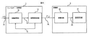
その手法として、例えば、図6に示すようなものが提案されている。すなわち、図6に示す如く、入力14(列車速度などの制御情報)を受け、所望の制御演算を実行する制御演算部10と該制御演算部の故障を検知する故障検知回路11を含むフェイルセーフ演算部1及び故障検知回路11の出力データ16を受け、所望の制御を実行する制御回路20と該制御回路の出力情報、つまり故障情報を地上設備側の無線基地5(無線通信装置)にデータを通信する通信回路21を含む通信制御部2を備えたフェイルセーフ制御装置や列車制御装置である。
For example, a method as shown in FIG. 6 has been proposed. That is, as shown in FIG. 6, a fail safe including an input 14 (control information such as train speed) and a
故障検知回路11を含むフェイルセーフ演算部1(フェイルセーフコントローラ)は、制御演算部10に対する故障検知処理を行い、その処理結果を交番信号または固定値信号である故障検知信号15を制御回路20に出力するものである。係る構成については、例えば特許文献2、3にて知られている。また、制御装置や通信回路の状態監視を行い、故障検知時に通信回路の回線切断を行なう方法としては、例えば特許文献4にて知られている。
The fail-safe operation unit 1 (fail-safe controller) including the
フェイルセーフ制御装置や列車制御装置のフェイルセーフ演算部1の制御演算部10は図7に示す如く、安全性を高めることを目的に2つのCPU101、102を備え、二重化構成となっている。
As shown in FIG. 7, the
故障検知回路11は制御演算部10のCPU101、102に故障がないか否か検知し、その検知処理結果を通信データ16として通信制御部2の通信回路21に出力する。また、CPU101,102に故障が発生した場合は、故障信号15を出力し、通信制御部2の制御回路20に送信する。
The
通信制御部2において、通信回路21はクロック生成回路30より出力されるクロック信号の周波数31を基にボーレートを生成し、フェイルセーフ演算部1と外部装置との通信を行なう。クロック生成回路30は通信回路21がボーレート生成するのに必要なクロック信号33を通信回路21に供給するものである。
In the
制御回路20は故障検知信号15を入力とし、故障検知信号15が正常を示す時は図7に示すように通信回線23上の接点22を閉状態にして通信回線23を維持し、通信データ16の通信を可能とする。故障検知信号15が故障を示すときには、図8に示すように接点22を開状態にし、通信回線23を物理的に切断する。この接点の開閉制御により通信データ16の通信を継続または遮断する。
The
係る構成によれば、フェイルセーフ演算部1で故障が発生した際に、誤った通信データが送信されることによる誤動作を防止することができる。 According to such a configuration, when a failure occurs in the fail safe arithmetic unit 1, it is possible to prevent malfunction due to transmission of erroneous communication data.
しかし、従来技術にあっては、通信回路21の出力段に接点22を設け、該接点を故障検知時に物理的に開閉制御するものである。従って、そのための制御回路20と、接点と、制御回路を駆動するためのクロック生成回路30と、を必要とするものであることから、回路構成が複雑、大型化となる課題があった。また、制御回路20の故障時には通信回線23が切断されず誤った通信データが送信されてしまうという問題があった。
However, in the prior art, a
本発明の目的は、係る課題に鑑みなされ、制御演算部などの故障のとき、簡易な構成により、通信回線を通じた通信制御することが可能な制御装置及び制御システムを提供することにある。または、誤った通信データの送信をより確実に防止できる制御装置及び制御システムを提供することにある。 An object of the present invention is to provide a control device and a control system capable of controlling communication through a communication line with a simple configuration when a failure occurs in a control arithmetic unit or the like. Another object of the present invention is to provide a control device and a control system that can prevent transmission of erroneous communication data more reliably.
上記目的を達成するため、本発明では、例えば制御演算部の故障を検知する故障検知部及び該故障検知部からの出力を他の装置に通信する通信制御部を備えた制御装置又は制御システムにおいて、前記故障検知部の故障検知信号を受け、該信号から通信制御部の通信を制御する制御信号を生成する制御信号生成手段を設けたことを特徴とする。 In order to achieve the above object, in the present invention, for example, in a control device or control system including a failure detection unit that detects a failure of a control calculation unit and a communication control unit that communicates an output from the failure detection unit to another device. And a control signal generation means for receiving a failure detection signal from the failure detection unit and generating a control signal for controlling communication of the communication control unit from the signal.
制御信号生成手段としては、例えばフェイルセーフ演算部の故障検知部の故障検知信号を受け、該信号の周波数を通信制御部の通信回路の通信に必要なクロックとなり得る周波数に変換する周波数変換手段である。 As the control signal generation means, for example, a frequency conversion means that receives a failure detection signal of the failure detection unit of the fail safe arithmetic unit and converts the frequency of the signal into a frequency that can be a clock necessary for communication of the communication circuit of the communication control unit. is there.
本発明によれば、従来必要とされていた回線切断のための制御回路及び接点などを不要にすることが可能となり、装置の縮小化が可能となる。または、誤った通信データの送信をより確実に防止できる。 According to the present invention, it is possible to eliminate the need for a control circuit and a contact for disconnecting a line, which have been conventionally required, and to reduce the size of the apparatus. Alternatively, transmission of erroneous communication data can be prevented more reliably.
以下、本発明の実施例について図面を用いて説明する。
まず、本発明における制御装置に故障が発生した場合についての手法及びフェイルセーフ演算部、通信回線の切断の基本動作について、説明する。
Embodiments of the present invention will be described below with reference to the drawings.
First, a method when a failure occurs in the control device according to the present invention, a fail safe arithmetic unit, and a basic operation of disconnecting a communication line will be described.
フェイルセーフ演算部1の故障検知回路11は制御演算部10の状態を入力12として取り込み、演算部10の故障検知処理を行なう。故障検知回路11は前記故障検知処理の結果を一定周期の交番信号または固定値信号に変換して故障検知信号15として出力する。
The
通信制御部2は故障検知回路11からの入力15(故障検知信号)が故障を示す信号のときに通信回路21を安全な状態で駆動し、入力がそれ以外のときに緊急停止等の処置を行う。
The
故障検知回路11からの入力15(故障検知信号)による緊急停止等の処置を行う構成として、図6,7,8に示す従来技術の構成によれば、故障発生時における通信データによる誤動作を防止することができるが、上述したように、回路構成の複雑、大型化や誤った通信データの送信という問題があった。
According to the configuration of the prior art shown in FIGS. 6, 7, and 8 as a configuration for performing an emergency stop or the like by the input 15 (failure detection signal) from the
本発明の一実施形態は、斯様な問題を是正するために例えば列車制御装置または制御システムにおいて、例えば通信回路に必要なクロック信号を故障検知信号に基づき生成する手段、例えば周波数変換手段を設けたものである。 In order to correct such a problem, an embodiment of the present invention is provided with a means for generating a clock signal necessary for a communication circuit based on a failure detection signal, for example, a frequency conversion means, for example, in a train control device or a control system. It is a thing.
以下、本発明の詳細な実施形態について、図1〜図5を参照して説明する。以下の実施例は、無線通信を用いた移動閉塞方式の信号保安システムにおける自動列車制御装置ATCに適用した場合である。なお、図6〜図8に示した従来技術と同一部分には同一番号を付す。 Hereinafter, detailed embodiments of the present invention will be described with reference to FIGS. The following embodiment is a case where the present invention is applied to an automatic train control device ATC in a mobile block signal protection system using wireless communication. In addition, the same number is attached | subjected to the same part as the prior art shown in FIGS.
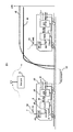
まず、図1において、移動閉塞方式の信号保安システムにおける自動列車制御装置ATCについて簡単に説明する。 First, referring to FIG. 1, an automatic train control device ATC in a mobile blockage type signal security system will be briefly described.
列車の保安装置の制御部40は、例えば自列車の走行速度46や車輪径といった情報と、地上設備(無線基地5)側より受信した情報を基に列車の位置を演算し、該演算に基づく位置情報50を、無線装置42を介して地上の無線基地5へと通信し報告する。
The
無線基地5は、各列車から受けとった位置情報50を基に、各列車へ各列車の停止目標位置やその区間における制限速度等、列車を安全に制御するために必要な制御情報51を無線にて送信する。
Based on the
各列車は、それらの制御情報51を無線装置42経由で受信する。無線装置42が制御情報51を受信すると、制御部40は制御情報51と、減速性能等の自列車内に保有している情報に基づき制限速度パターン45を算出する。
Each train receives the
算出された制限速度パターン45は、速度照査部41にて列車の走行速度46と比較照査され、列車が安全に走行できるよう制御される。具体的には、走行速度46が制限速度を超過した際にブレーキ指令43を出力(ブレーキ出力)し、列車が前方の列車との安全余裕距離52を確保した状態で停止し、衝突することのないよう制御する。
The calculated
また、保安に係る演算、処理を行なう制御部40及び速度照査部41にて装置の故障が検知された際には安全な制御ができる保障がなくなるため、上記同様にブレーキ指令43が出力される構造となっている。
In addition, when a malfunction of the apparatus is detected by the
フェイルセーフ演算部が通信処理を行なう装置としては、車上装置と地上装置間の通信、若しくは車上装置内における制御部と無線装置の通信が上げられる。
以下、本実施例では、車上装置内の制御部の無線装置へのインタフェースを例にとり説明するが、本発明は車上装置内の制御部に限定されるものではなく、例えば車上装置外の制御部にも適用可能である。
As a device that the fail-safe arithmetic unit performs communication processing, communication between the on-board device and the ground device, or communication between the control unit and the wireless device in the on-board device is raised.
Hereinafter, in the present embodiment, the interface of the control unit in the on-board device to the wireless device will be described as an example. However, the present invention is not limited to the control unit in the on-board device. It is also applicable to the control unit.
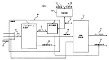
図4は車上装置、つまり列車内の制御部40(列車制御装置)の概略ブロック図である。制御部40内での演算処理は、主にフェイルセーフ演算部1により行われる。フェイルセーフ演算部1は、現在の列車速度46や、運転士の操作や他装置の状態等、その他の入力情報47を列車の制御に必要な情報を入力14として取り込む。また、無線装置42と通信制御部2を介して受信される制御情報51等、列車内に装着された他装置とのやり取りで入手した情報を通信データ16として取り込む。これらの取り込まれた情報を基に、フェイルセーフ演算部1は各種の演算処理と故障検知を行う。この演算処理と故障検知は周知方法で実現すれば良い。
FIG. 4 is a schematic block diagram of the on-vehicle device, that is, the control unit 40 (train control device) in the train. Arithmetic processing in the
フェイルセーフ演算部1により行われた各種演算処理の結果(通信データ16)は、他装置へと送信され、実際の列車制御やシステムの制御に使用される。例えば、図4に示す如く、フェイルセーフ演算部1により生成される制限速度パターン45は速度照査部41に送信され、速度照査部41により、現在の列車速度46と比較照査され、必要であればブレーキ指令の出力43を行う等して列車を制御する。
The results (communication data 16) of various arithmetic processes performed by the fail safe arithmetic unit 1 are transmitted to other devices and used for actual train control and system control. For example, as shown in FIG. 4, the
また、他装置や地上設備側への通信を行う際は、フェイルセーフ演算部1より制御部内の通信制御部2を介して他装置との伝送処理を行う。
図4では、例として無線装置42への通信インタフェースを記している。通信制御部2では、フェイルセーフ演算部1により生成される通信データ16の他に、故障検知信号44を入力として取り込み、他装置への通信データの受け渡しだけでなく、故障時における回線切断等の通信回路の制御も行う。
Moreover, when performing communication to the other device or the ground facility side, the fail safe calculation unit 1 performs transmission processing with the other device via the
FIG. 4 shows a communication interface to the
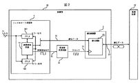
以下、制御部40内の構成例について、図2を参照して説明する。すなわち、本実施例におけるフェイルセーフ演算部1と、通信制御部2の動作を具体的に説明する。
Hereinafter, a configuration example in the
制御部40は、入力14(列車速度などの制御情報)に対する処理と、その処理結果であるデータ16の出力を行なう2重化されたCPU101、102と、そのCPUの健全性を確認する故障検知回路11を有するフェイルセーフ演算部1を備え、さらに、フェイルセーフ演算部1と外部装置(例えば無線装置42)との通信を行う際に通信データの送受信を行なう通信回路21を有する通信制御部2と、通信回路21がボーレート生成するのに必要なクロック33を供給する周波数変換回路32と、を有している。
The
CPU101、CPU102は列車速度などの制御情報を入力14とし、入力14に対する演算処理と、その演算結果である通信データ16の出力を行なう。故障検知回路11は、二重化されたCPU101,102の健全性を確認し、故障を検知したとき、故障検知信号15を出力する。例えば、故障検知回路15として2つのCPU(プロセッサモジュール)における対応する信号の一致/不一致を検知してフェイルセーフ演算部1(半導体チップ)の外部に故障検知信号15を出力する比較回路である。比較すべき信号としては、CPU101とCPU102におけるCPUバスの書き込みデータ、制御回路のアドレス信号及び演算器が出力する演算フラグなどである。故障検知信号15は、前述したように正常時には交番信号(ロウレベル)であり、故障時にはそれ以外(ハイレベル)となる。
The
制御部40は入力14として前述の制御情報を取り込み、フェイルセーフ演算部1で演算処理を行なう。フェイルセーフ演算部1内では、二重化された演算処理部であるCPU101、CPU102での制御情報を基に、例えば停止限界位置や制限速度から算出される、制限速度パターンの演算や、自列車速度や自列車車輪径等の情報から算出される自列車の現在位置等の演算処理を実施し、その処理結果を故障検知回路11で付き合わせる。
The
故障検知回路11は、演算処理部のCPU101、102の健全性を確認し、故障検知信号15を出力する。故障検知回路11の演算処理部の健全性を判断する方法は、多重化された演算処理部のCPU101,CPU102から出力される演算結果を比較照査し、一致や多数決にて正常部を判断する方法や演算処理部の内部に故障検知回路を内蔵し、自己診断を行なうもの等がある。
The
本構成では、故障検知回路11は、前者の演算処理部のCPU101、CPU102の出力を比較照査する例で説明している。故障検知回路11は両CPU101、CPU102の演算結果を比較し、一致している間は、正常と判断し、故障検知信号15として一定周期の交番信号を出力する。CPU101、CPU102の演算結果が一致しない場合は、故障検知信号15には電気的に高位(Hight)か低位(Low)に固定された固定信号が出力される。
In this configuration, the
周波数変換回路32は故障検知回路11からの故障検知信号15を受け、通信制御部7の通信を制御する制御信号(クロック信号/通信ボーレート)を生成する制御信号生成手段(クロック信号生成手段/通信ボーレート生成手段)を構成している。具体的には、故障検知信号15の周波数を通信制御部2の通信回路21で必要とされるクロック信号33となり得る周波数に変換する周波数変換回路である。
The
通信制御部2にはフェイルセーフ演算部1から、他装置へと送信する通信データ16(データ内容)と、故障検知信号15を周波数変換回路32により周波数変換したクロック信号33が入力される。
The
通信回路21は、クロック信号33を受け、設定された通信速度のボーレートを生成し、また、例えば無線装置42経由で地上設備の無線基地5(図1参照)へと送信される自列車の位置情報等の通信データ16を受け、地上設備の他装置との通信に適したフォーマットに変換し、通信データ23を他装置へと送信する。
The
故障検知信号15は、一定周期の交番信号として出力されるため、クロック信号33と等価の信号である。しかし、故障検知信号15として使われる交番信号は、制御周期が長い装置への入力として使われるため、通信回路21に必要となるクロック周波数f1より低い周波数f2が使われる。また、この周波数f2は通信回路21の通信速度に応じて設定される。
通信速度は周波数f2を分周する事により生成される。通信回路21により、係数や計算式は異なるが、例えば、通信ボーレートSを2つの係数a,Nを含むS=f2 / ((2^a)×N)で設定し、aは0〜8、Nは1〜255の間の整数で設定できる通信回路があるとする。入力であるf2が28MHzである際に、9600bpsを生成しようとすると、0.11%の誤差が出るが36MHzであれば0%の誤差でボーレートを生成できる。38400bpsを生成しようとする際には、f2が28MHzで約0.023%の誤差、36MHzで0.053%の誤差がでる。
以上の様に、入力するクロック信号の周波数により、通信速度の誤差が異なるため、使用したい通信速度に合わせて、入力するクロック信号の周波数を変更する必要がある。
また、このクロック信号の周波数f2の設定は通信回路21の通信速度を自動的に検出して周波数変換回路32の周波数が変化するように制御する構成としても良く、手動により切り替えるように構成しても良い。
The
Communication speed is generated by dividing the frequency f 2. For example, the communication baud rate S is set to S = f 2 / ((2 ^ a) × N) including two coefficients a and N, where a is 0-8. , N is assumed to be a communication circuit that can be set as an integer between 1 and 255. When 9600 bps is generated when the input f 2 is 28 MHz, an error of 0.11% is generated, but if it is 36 MHz, a baud rate can be generated with an error of 0%. When attempting to generate a 38400bps is about 0.023% of errors f 2 is at 28 MHz, 0.053% error comes out at 36 MHz.
As described above, since the communication speed error varies depending on the frequency of the input clock signal, it is necessary to change the frequency of the input clock signal in accordance with the communication speed to be used.
The setting of the frequency f 2 of the clock signal may be configured to control so as to automatically detect the frequency of the
よって、故障検知信号15を通信回路21のボーレート生成用クロック(通信速度の制御用クロック)として適したクロック信号周波数33となるように周波数変換回路32を通して、周波数を変換する。変換されたクロック信号周波数33はクロックとして通信回路21に入力されることにより、通信回路21を駆動する。
Therefore, the frequency is converted through the
ここで、通信回路21のボーレート生成用のクロック信号周波数の入力と、フェイルセーフ演算部1からの通信データ16を基に通信回路21により通信データ23を生成し、当該通信データ23を出力する仕組みの例について図5を用いて説明する。
Here, the
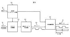
図5は通信回路21内部の、データ送信に関わる部分の構成例である。
通信回路21は、フェイルセーフ演算部1からの通信データ16と、故障検知信号15が周波数変換回路32にて適正な周波数に変換されたクロック信号33を入力として取り込む。
通信データ16は通信制御部2の演算部インタフェース回路211を介して、通信制御部2の送信制御回路215に供給される。また、クロック信号33はボーレート生成等に関する制御情報としてクロック分周回路212に供給される。
FIG. 5 is a configuration example of a portion related to data transmission in the
The
The
クロック分周回路212は、前述のクロック信号33と、演算部インタフェース回路1(演算部インターフェース回路211)からの制御信号に従い、クロック信号33の周波数を分周して分周クロックを出力する。通信ボーレート生成回路213はクロック分周回路211の分周クロックを受けて通信ボーレート214を生成する。通信ボーレート214とは、1秒当たりにデジタルデータの変復調可能回数である。
The clock
すなわち、ボーレートを生成することにより、データの変復調の回数を定義する。送信制御回路215は定義されたボーレートにより通信データのビット幅等を演算し、演算部インタフェース回路211を介して渡される通信データ16を変復調し、通信回線上に通信データ23として出力する。
That is, the number of times of data modulation / demodulation is defined by generating a baud rate. The
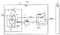
フェイルセーフ演算部1にて、故障が検出された際には、故障検知信号15の交番信号が電気的に高位(Hight)か低位(Low)に固定された信号が出力される。周波数変換回路32に当該固定信号が入力されると、周波数変換回路32は、図3に示す如く、クロック信号を生成できず、通信回路21にはボーレート生成用のクロック信号33として固定信号が入力される。これによって通信回路21は動作が停止状態となる。
When a failure is detected by the fail safe arithmetic unit 1, a signal in which the alternating signal of the
ボーレートは、通信回路21に入力されるボーレート生成用のクロック信号33に分周等の処理を行い生成されるものである。クロック信号33が固定信号となることにより、通信回路21内部でのボーレート生成ができなくなる。これにより、送信制御回路215の通信データを変復調する機能が停止し、フェイルセーフ演算部1からの通信データ16を基に通信回線23上に送信する通信データの入出力ができなくなる。すなわち、制御部40は通信データの入出力不可の状態となる。
The baud rate is generated by performing processing such as frequency division on the
よって、フェイルセーフ演算部1にて故障が検出された際、制御部40は通信データ23を出力できないため,通信データ23の通信回線が電気的に切断される。なお、故障検知信号15の通信回線が短絡、または断線した際も、信号は交番信号とならず、片側に固定されるため、故障状態となり、通信回路21は停止する。
Therefore, when the failure is detected by the fail safe arithmetic unit 1, the
以上述べた実施例によれば、フェイルセーフ演算部1の故障時、または、故障検知信号15の通信回線が短絡/断線した時に、通信回路21が確実に通信データを出力できなくなる(回線から切断される)伝送装置を簡易な構成により、実現することができる。
According to the embodiment described above, the
また、本実施例によれば、故障検知信号の周波数変換回路32が、従来技術のクロック生成回路に置き換わり、周波数変換された故障検知信号が通信回路のクロックとして入力されるため、故障検出時の制御回路及び回線切断をする、接点部が不要になり、従来構成に対し、回路構成が縮小される。
In addition, according to the present embodiment, the
また、本実施例では、通信回路からの意図しないデータの出力をより確実に止めることができる。通信回路のクロック供給停止は、通信回線へのデータ出力処理自体を停止させることになる。よって従来の誤ったデータが回線上に出力されることを前提とした、物理的な回線切断よりも確実に誤出力を阻止することができる。また、故障検知回路の出力から通信回線切断を制御する回路構成が簡易化され、回線切断までの処理が減ることから、より早く回線の切断が行われることになる。以上2点により、本実施例では通信回路からの意図しないデータの出力の阻止を、従来構成と比べより確実に実現できる。 In this embodiment, unintended data output from the communication circuit can be stopped more reliably. Stopping the clock supply of the communication circuit stops the data output processing itself to the communication line. Therefore, erroneous output can be more reliably prevented than physical line disconnection based on the assumption that conventional erroneous data is output on the line. In addition, the circuit configuration for controlling the communication line disconnection from the output of the failure detection circuit is simplified, and the processing until the line disconnection is reduced, so that the line is disconnected earlier. Due to the above two points, in this embodiment, prevention of unintended data output from the communication circuit can be realized more reliably than in the conventional configuration.
更に、回路構成や回路を構成する部品が少なくなる効果は単純にコストが低減されるだけではなく、故障率の低下に繋がる。回路構成が簡易になり部品数が少なくなることは、システム全体として故障する要因が減ることになる。システムとしての故障要因減少は即ち、システムとしての故障率低減になる。 Furthermore, the effect of reducing the circuit configuration and the number of parts constituting the circuit not only reduces the cost, but also leads to a decrease in the failure rate. If the circuit configuration is simplified and the number of parts is reduced, the cause of failure of the entire system is reduced. The failure factor reduction as a system means a failure rate reduction as a system.
上記実施例においては、フェースセーフ演算部の故障検知信号に基づく通信回路の切断を列車(鉄道)制御装置に適用したことを前提に説明しているが、この制御装置は、列車制御装置に特定されるものではなく、装置の故障が検知された際に、通信回路の遮断を含め動作の停止が安全性を確保する上で必要な装置にも適用可能である。例えば、工場の製造ライン装置や信号機等の分野に適用できる。 In the above embodiment, the description has been made on the assumption that the disconnection of the communication circuit based on the failure detection signal of the face-safe arithmetic unit is applied to the train (railway) control device, but this control device is specific to the train control device. The present invention is not limited to this, and can be applied to a device that is required to stop the operation including the interruption of the communication circuit to ensure safety when a failure of the device is detected. For example, the present invention can be applied to fields such as factory production line devices and traffic lights.
上記実施例においては、交番信号である故障検知信号を周波数変換回路により周波数変換して、通信回路へのクロック信号を生成する構成を説明したが、本発明は当該実施形態に限られない。例えば、故障検知信号15をクロック生成回路30に入力される構成とし、クロック生成回路は、故障検知信号が故障を示す信号である場合に、クロック生成を停止させる機能、つまり高位(Hight)か低位(Low)に固定された信号のみを出力させる機能を有する実施形態によっても、本発明の効果を達成することができる。
In the above embodiment, the configuration has been described in which the fault detection signal, which is an alternating signal, is frequency-converted by the frequency conversion circuit to generate the clock signal to the communication circuit, but the present invention is not limited to this embodiment. For example, the
また、故障を示す故障検知信号が故障検知回路で生成された場合に、通信回路へクロック信号が入力されることを防止する手段、またはクロック信号の生成そのものを停止させる手段を有し、通信回路に高位(Hight)か低位(Low)に固定された信号のみを出力させて、通信回路で通信データ23を生成すること自体を不可能とする実施形態も有り得る。当該実施形態によっても通信回路からの意図しないデータが出力されることを阻止し、従来よりも確実に行うことができる。
In addition, when a failure detection signal indicating a failure is generated by the failure detection circuit, the communication circuit has means for preventing the clock signal from being input to the communication circuit, or means for stopping the generation of the clock signal itself. There may be an embodiment in which it is impossible to generate the
1 フェイルセーフ演算部
11 故障検知回路
15 故障検知信号
16 クロック信号
101、102 CPU
2 通信制御部
21 通信回路
4 列車
40 制御部(制御装置)
41 速度照査部
42 無線装置
43 ブレーキ指令(ブレーキ出力)
44 故障検知信号
45 制御速度信号
46 列車速度信号
5 無線基地
214 通信ボーレート
DESCRIPTION OF SYMBOLS 1 Fail safe calculating
2
41
44
Claims (8)
前記フェイルセーフ演算部から出力される前記通信データを受け、クロック信号を用いて該通信データを変復調して外部装置に通信する通信制御部と、
クロック信号を前記通信制御部へ供給するクロック信号生成手段と、を備え、
前記クロック信号生成手段は、前記故障検知回路から前記故障検知信号を受信しており、故障を意図する前記故障検知信号を受けた場合に、前記クロック信号の生成を停止、または固定信号を生成することを特徴とする制御装置。 A CPU that processes input signals and outputs communication data; and a fail-safe arithmetic unit that includes a failure detection circuit that detects a failure of the CPU and outputs a failure detection signal;
A communication control unit that receives the communication data output from the fail-safe operation unit, modulates and demodulates the communication data using a clock signal, and communicates to an external device;
A clock signal generating means for supplying a clock signal to the communication control unit,
The clock signal generation means receives the failure detection signal from the failure detection circuit, and stops generation of the clock signal or generates a fixed signal when the failure detection signal intended for failure is received. A control device characterized by that.
前記故障検知回路は、故障を検知しない場合には前記故障検知信号として交番信号を出力し、
前記クロック信号生成手段は、前記故障検知信号として交番信号を受け、該交番信号の周波数を通信制御部で行われる通信データの変復調に必要な周波数に変換して前記クロック信号を生成する周波数変換手段であることを特徴とする制御装置。 The control device according to claim 1,
The failure detection circuit outputs an alternating signal as the failure detection signal when no failure is detected,
The clock signal generation means receives an alternating signal as the failure detection signal, converts the frequency of the alternating signal to a frequency required for modulation / demodulation of communication data performed by a communication control unit, and generates the clock signal. The control device characterized by being.
前記通信制御部は、
周波数変換された前記クロック信号を、前記フェイルセーフ演算部からの通信データに基づき分周して分周信号を出力するクロック分周回路と、
該クロック分周回路の前記分周信号から通信ボーレートを生成する通信ボーレート生成回路と、を有することを特徴とする制御装置。 The control device according to claim 2, wherein
The communication control unit
A clock frequency dividing circuit for frequency-dividing the frequency-converted clock signal based on communication data from the fail-safe operation unit and outputting a frequency-divided signal;
And a communication baud rate generating circuit for generating a communication baud rate from the frequency-divided signal of the clock frequency dividing circuit.
前記通信制御部は、前記故障検知回路が前記CPUの故障を検出したとき、前記故障検知回路から固定信号からなる故障検知信号を受け、前記通信制御部へのクロック信号の供給を停止、または固定信号を供給する制御手段であることを特徴とする制御装置。 In the control device according to any one of claims 1 to 3,
The communication control unit receives a failure detection signal including a fixed signal from the failure detection circuit when the failure detection circuit detects a failure of the CPU, and stops or fixes the supply of the clock signal to the communication control unit. A control device characterized by being a control means for supplying a signal.
前記CPUの処理結果を監視して故障を検知し、故障検知信号を交番信号または固定信号として出力すると共に、前記処理結果を通信データとして出力する故障検知回路と、
前記通信データを入力として取り込み、取り込んだ通信データをクロック信号に基づいて外部装置に通信可能なデータを生成する通信回路と、
前記故障検知回路より出力される交番信号または固定信号を取込み、前記交番信号を取り込んだとき、外部装置への通信可能なデータを前記通信回路で生成するためのクロック信号を出力し、
前記固定信号を取り込んだとき、外部装置への通信可能なデータを前記通信制御部で生成するためのクロック信号を出力しない通信制御手段と、
を設けたことを特徴とする列車制御装置。 A CPU that processes control information used for control of the railway vehicle as an input signal;
A failure detection circuit that monitors a processing result of the CPU to detect a failure, outputs a failure detection signal as an alternating signal or a fixed signal, and outputs the processing result as communication data;
A communication circuit that captures the communication data as an input and generates the data that can be communicated to an external device based on the clock signal;
Taking in the alternating signal or fixed signal output from the failure detection circuit, when taking in the alternating signal, to output a clock signal for generating data communicable to an external device in the communication circuit,
Communication control means that does not output a clock signal for generating data that can be communicated to an external device in the communication control unit when the fixed signal is captured;
A train control device characterized by comprising:
前記通信制御手段は、前記故障検知信号の交番周波数を、前記通信回路が外部装置に通信可能なデータの生成に適した交番周波数に変換する周波数変換装置であり、
前記周波数変換装置は、変換した交番周波数のクロック信号を前記通信回路へ入力することを特徴とする列車制御装置。 In the train control device according to claim 5,
The communication control means is a frequency conversion device that converts an alternating frequency of the failure detection signal into an alternating frequency suitable for generating data that the communication circuit can communicate with an external device,
The said frequency converter inputs the clock signal of the converted alternating frequency into the said communication circuit, The train control apparatus characterized by the above-mentioned.
前記故障検知回路は、前記CPUの故障を検出した際には、前記故障検知信号を固定信号として出力し、
前記通信制御手段は、外部装置への通信可能なデータを前記通信制御部で生成するためのクロック信号の出力を停止して、前記通信回路による通信動作を停止させることを特徴とする列車制御装置。 In the train control device according to claim 5 or 6,
When the failure detection circuit detects a failure of the CPU, it outputs the failure detection signal as a fixed signal,
The communication control unit stops output of a clock signal for generating data communicable with an external device by the communication control unit, and stops a communication operation by the communication circuit. .
前記CPUの演算結果を監視し、該演算結果を通信データとして出力し、かつ前記CPUが正常動作のときは故障信号として交番信号を出力し、前記CPUの故障を検出したときは故障検知信号として固定信号を出力する故障検知回路と、
前記CPUの演算結果の前記通信データを入力として取込み、該取り込んだ入力をクロック信号に基づいて、他装置へ通信する通信回路と、
前記通信回路の通信データを地上設備側に通信する無線装置と、
前記故障検知回路より出力される前記交番信号または前記固定信号を取込み、前記交番信号を取り込んだとき、前記通信回路をもって前記通信データの通信を継続し、前記固定信号を取り込んだとき、前記クロック信号として前記通信制御部の通信回路による通信データの通信を遮断する制御信号を生成する通信制御手段を設けたことを特徴とする列車制御システム。 A CPU that takes in control information for running and stopping the railway vehicle as input and performs arithmetic processing;
Monitors the calculation result of the CPU, outputs the calculation result as communication data, outputs an alternating signal as a failure signal when the CPU is operating normally, and detects a failure of the CPU as a failure detection signal A failure detection circuit that outputs a fixed signal;
A communication circuit that takes in the communication data of the calculation result of the CPU as an input, and communicates the acquired input to another device based on a clock signal;
A wireless device for communicating communication data of the communication circuit to the ground equipment side;
The alternating signal or the fixed signal output from the failure detection circuit is captured, and when the alternating signal is captured, communication of the communication data is continued with the communication circuit, and when the fixed signal is captured, the clock signal As a train control system, a communication control means for generating a control signal for interrupting communication of communication data by the communication circuit of the communication control unit is provided.
Priority Applications (1)
| Application Number | Priority Date | Filing Date | Title |
|---|---|---|---|
| JP2011038767A JP5694806B2 (en) | 2011-02-24 | 2011-02-24 | Control device, train control device, and train control system |
Applications Claiming Priority (1)
| Application Number | Priority Date | Filing Date | Title |
|---|---|---|---|
| JP2011038767A JP5694806B2 (en) | 2011-02-24 | 2011-02-24 | Control device, train control device, and train control system |
Publications (2)
| Publication Number | Publication Date |
|---|---|
| JP2012174221A true JP2012174221A (en) | 2012-09-10 |
| JP5694806B2 JP5694806B2 (en) | 2015-04-01 |
Family
ID=46977032
Family Applications (1)
| Application Number | Title | Priority Date | Filing Date |
|---|---|---|---|
| JP2011038767A Expired - Fee Related JP5694806B2 (en) | 2011-02-24 | 2011-02-24 | Control device, train control device, and train control system |
Country Status (1)
| Country | Link |
|---|---|
| JP (1) | JP5694806B2 (en) |
Cited By (2)
| Publication number | Priority date | Publication date | Assignee | Title |
|---|---|---|---|---|
| WO2018207480A1 (en) * | 2017-05-11 | 2018-11-15 | 株式会社日立製作所 | Automatic train protection device and on-board device |
| JP2018207649A (en) * | 2017-06-02 | 2018-12-27 | 株式会社日立製作所 | Vehicle control device |
Families Citing this family (1)
| Publication number | Priority date | Publication date | Assignee | Title |
|---|---|---|---|---|
| KR101750384B1 (en) * | 2015-11-23 | 2017-06-27 | 한국철도기술연구원 | System and method for detecting train movement of train control sysrem |
Citations (9)
| Publication number | Priority date | Publication date | Assignee | Title |
|---|---|---|---|---|
| JPH02109770A (en) * | 1988-10-19 | 1990-04-23 | Railway Technical Res Inst | Radio controlled mobile block type automatic train control method |
| JPH07183803A (en) * | 1993-12-24 | 1995-07-21 | Fujitsu Ltd | Signal processing device having PLL circuit |
| JPH07295844A (en) * | 1994-04-28 | 1995-11-10 | Hitachi Ltd | Fail-safe control device and train control device |
| JP2000039902A (en) * | 1998-07-23 | 2000-02-08 | Hitachi Ltd | Fail safe controller |
| JP2000276202A (en) * | 1999-03-29 | 2000-10-06 | Hitachi Ltd | Fail safe controller |
| EP1132788A1 (en) * | 1998-07-23 | 2001-09-12 | Hitachi, Ltd. | Fail-safe controller |
| JP2009088880A (en) * | 2007-09-28 | 2009-04-23 | Hitachi Ltd | Communication disconnection circuit at the time of failure of wide area network communication equipment |
| JP2009265711A (en) * | 2008-04-22 | 2009-11-12 | Hitachi High-Technologies Corp | Control system |
| JP2010011389A (en) * | 2008-06-30 | 2010-01-14 | Digital Electronics Corp | Frequency divider |
-
2011
- 2011-02-24 JP JP2011038767A patent/JP5694806B2/en not_active Expired - Fee Related
Patent Citations (9)
| Publication number | Priority date | Publication date | Assignee | Title |
|---|---|---|---|---|
| JPH02109770A (en) * | 1988-10-19 | 1990-04-23 | Railway Technical Res Inst | Radio controlled mobile block type automatic train control method |
| JPH07183803A (en) * | 1993-12-24 | 1995-07-21 | Fujitsu Ltd | Signal processing device having PLL circuit |
| JPH07295844A (en) * | 1994-04-28 | 1995-11-10 | Hitachi Ltd | Fail-safe control device and train control device |
| JP2000039902A (en) * | 1998-07-23 | 2000-02-08 | Hitachi Ltd | Fail safe controller |
| EP1132788A1 (en) * | 1998-07-23 | 2001-09-12 | Hitachi, Ltd. | Fail-safe controller |
| JP2000276202A (en) * | 1999-03-29 | 2000-10-06 | Hitachi Ltd | Fail safe controller |
| JP2009088880A (en) * | 2007-09-28 | 2009-04-23 | Hitachi Ltd | Communication disconnection circuit at the time of failure of wide area network communication equipment |
| JP2009265711A (en) * | 2008-04-22 | 2009-11-12 | Hitachi High-Technologies Corp | Control system |
| JP2010011389A (en) * | 2008-06-30 | 2010-01-14 | Digital Electronics Corp | Frequency divider |
Cited By (3)
| Publication number | Priority date | Publication date | Assignee | Title |
|---|---|---|---|---|
| WO2018207480A1 (en) * | 2017-05-11 | 2018-11-15 | 株式会社日立製作所 | Automatic train protection device and on-board device |
| JPWO2018207480A1 (en) * | 2017-05-11 | 2020-02-27 | 株式会社日立製作所 | Automatic train security equipment and on-board equipment |
| JP2018207649A (en) * | 2017-06-02 | 2018-12-27 | 株式会社日立製作所 | Vehicle control device |
Also Published As
| Publication number | Publication date |
|---|---|
| JP5694806B2 (en) | 2015-04-01 |
Similar Documents
| Publication | Publication Date | Title |
|---|---|---|
| WO2009089313A2 (en) | Methods and systems for vital bus architecture | |
| JP5827509B2 (en) | Wireless train control system | |
| CN107244336B (en) | Side impact protection device and method based on direction information of secondary detection equipment | |
| KR20140000433A (en) | Train integrity monitoring system | |
| WO2018092028A1 (en) | Device and method for the safe management of vital communications in the railway environment | |
| JP5694806B2 (en) | Control device, train control device, and train control system | |
| JP5042066B2 (en) | Train control system | |
| EP3090911A1 (en) | Apparatus for warning of occurrence of error of device | |
| JP5800697B2 (en) | Railway signal security system | |
| CN110896307B (en) | Railway signal redundancy coding device and redundancy coding method | |
| CN113415264A (en) | Rail vehicle braking system and monitoring method thereof | |
| KR100945854B1 (en) | Quadrant communication fault detection circuit of dual system controller for railway signal | |
| KR102299977B1 (en) | Real-time Ballis Error Detector | |
| JP4164628B2 (en) | Fail-safe information processing device | |
| DK2559602T3 (en) | A method and device for the blocking of the traction of a stationary rail vehicle | |
| CN116946222B (en) | CBTC System Based on Spacing Protection and Heterogeneous Redundancy and Its Implementation Method | |
| JP2011136632A (en) | Railway security system | |
| CN115123339B (en) | A coding unit for station ground control system | |
| JP5161158B2 (en) | ATC transmitter | |
| CN106068216A (en) | Method for controlling rail vehicles connected to a CBTC system and CBTC system with at least one rail vehicle | |
| JP6505525B2 (en) | Level crossing control device | |
| KR101211912B1 (en) | Signal processing apparatus equipped on the ground for railway car | |
| CN206900392U (en) | A kind of side blow protector based on secondary detection device directional information | |
| KR100694511B1 (en) | Multiple Decision Defect Suppression Device for Wireless Train Control System Car Box | |
| EP3118052B1 (en) | Train information management device |
Legal Events
| Date | Code | Title | Description |
|---|---|---|---|
| A621 | Written request for application examination |
Free format text: JAPANESE INTERMEDIATE CODE: A621 Effective date: 20131203 |
|
| A977 | Report on retrieval |
Free format text: JAPANESE INTERMEDIATE CODE: A971007 Effective date: 20141010 |
|
| A131 | Notification of reasons for refusal |
Free format text: JAPANESE INTERMEDIATE CODE: A131 Effective date: 20141021 |
|
| A521 | Request for written amendment filed |
Free format text: JAPANESE INTERMEDIATE CODE: A523 Effective date: 20141217 |
|
| TRDD | Decision of grant or rejection written | ||
| A01 | Written decision to grant a patent or to grant a registration (utility model) |
Free format text: JAPANESE INTERMEDIATE CODE: A01 Effective date: 20150120 |
|
| A61 | First payment of annual fees (during grant procedure) |
Free format text: JAPANESE INTERMEDIATE CODE: A61 Effective date: 20150205 |
|
| R150 | Certificate of patent or registration of utility model |
Ref document number: 5694806 Country of ref document: JP Free format text: JAPANESE INTERMEDIATE CODE: R150 |
|
| LAPS | Cancellation because of no payment of annual fees |