JP2012175778A - Voltage reactive power control device - Google Patents
Voltage reactive power control device Download PDFInfo
- Publication number
- JP2012175778A JP2012175778A JP2011034378A JP2011034378A JP2012175778A JP 2012175778 A JP2012175778 A JP 2012175778A JP 2011034378 A JP2011034378 A JP 2011034378A JP 2011034378 A JP2011034378 A JP 2011034378A JP 2012175778 A JP2012175778 A JP 2012175778A
- Authority
- JP
- Japan
- Prior art keywords
- substation
- reactive power
- voltage
- vqc
- power
- Prior art date
- Legal status (The legal status is an assumption and is not a legal conclusion. Google has not performed a legal analysis and makes no representation as to the accuracy of the status listed.)
- Withdrawn
Links
Images







Classifications
-
- Y—GENERAL TAGGING OF NEW TECHNOLOGICAL DEVELOPMENTS; GENERAL TAGGING OF CROSS-SECTIONAL TECHNOLOGIES SPANNING OVER SEVERAL SECTIONS OF THE IPC; TECHNICAL SUBJECTS COVERED BY FORMER USPC CROSS-REFERENCE ART COLLECTIONS [XRACs] AND DIGESTS
- Y02—TECHNOLOGIES OR APPLICATIONS FOR MITIGATION OR ADAPTATION AGAINST CLIMATE CHANGE
- Y02E—REDUCTION OF GREENHOUSE GAS [GHG] EMISSIONS, RELATED TO ENERGY GENERATION, TRANSMISSION OR DISTRIBUTION
- Y02E40/00—Technologies for an efficient electrical power generation, transmission or distribution
- Y02E40/30—Reactive power compensation
Landscapes
- Supply And Distribution Of Alternating Current (AREA)
Abstract
【課題】簡易な構成で最適な電圧及び無効電力の制御が可能な電圧無効電力制御装置を提供することを課題とする。
【解決手段】調相設備SC,ShR及び変圧器TR−Sを有する所定変電所Sに設置する電圧無効電力制御装置1であって、前記所定変電所Sおよび該所定変電所Sよりも下流側の回路を模擬した回路モデルに、該所定変電所Sの上流側の電圧と該所定変電所が供給する有効電力および無効電力を入力し、該所定変電所Sの下流側の電圧と該所定変電所Sが供給する無効電力が規定の条件を満たすこととなる前記変圧器TR−Sのタップと前記調相設備SC,ShRの制御量を算出する演算部3と、前記演算部3が決定した制御量に基づいて前記調相設備SC,ShRと前記タップとを制御する制御部5と、を備える。
【選択図】図3An object of the present invention is to provide a voltage reactive power control device capable of controlling optimum voltage and reactive power with a simple configuration.
A voltage reactive power control device (1) installed in a predetermined substation (S) having phase adjusting facilities (SC, ShR) and a transformer (TR-S), the downstream side of the predetermined substation (S) and the predetermined substation (S). The voltage upstream of the predetermined substation S and the active power and reactive power supplied by the predetermined substation S are input to the circuit model simulating the circuit of the circuit, and the voltage downstream of the predetermined substation S and the predetermined substation The calculation unit 3 for calculating the control amount of the taps of the transformer TR-S and the phase adjusting equipment SC and ShR that the reactive power supplied by the station S will satisfy the specified condition is determined by the calculation unit 3 And a control unit 5 that controls the phase adjusting equipment SC, ShR and the tap based on a control amount.
[Selection] Figure 3
Description
本発明は、電圧無効電力制御装置に関する。 The present invention relates to a voltage reactive power control apparatus.
電力系統は、調相設備で系統の無効電力のバランスを図りながら、電圧調整器で需要家電圧を適正に維持している。系統の無効電力は系統構成や負荷潮流の変化によって絶えず変動し、無効電力が不足すれば系統電圧は低下するし、過剰になれば上昇する。そこで、系統の電圧および無効電力を適正に制御すべく、各種技術が開発されている(例えば、特許文献1〜6を参照)。
The electric power system maintains the consumer voltage appropriately with the voltage regulator while balancing the reactive power of the system with the phase adjusting equipment. The reactive power of the system constantly fluctuates due to changes in the system configuration and load flow, and the system voltage decreases when the reactive power is insufficient, and increases when it becomes excessive. Thus, various techniques have been developed to appropriately control the system voltage and reactive power (see, for example,
電力系統にとって適正な無効電力量は系統構成や負荷潮流の変化によって時々刻々と変動している。このため、各変電所の電圧無効電力制御装置(VQC)では、例えば、2次側の電圧変動に応じてタップを切り替え、1次側の電圧変動に応じて調相設備を制御している。しかし、この場合、実需要が想定した需要曲線と乖離し得るため、最適な電圧調整や調相制御が実現されるとは言い難い。特に、先行技術文献においては、特許文献2で変圧器のタップの検討がなされているが、目標とする無効電力と電圧に収めるための制御量を議論しているに過ぎず、すべての特許文献で調相設備と変圧器のタップの関係について整理されたものはない。また、無効電力Qや電圧Vを独立して検出して調相設備や変圧器のタップを制御する場合には、昼と夜の感度、つまり送電線の有効電力や変電所の無効電力の変化量に対する、送電線の無効電力や変電所の電圧値の変化率が異なるために、同じ有効電力の変化量に対して制御すべき対象が無効電力であったり電圧であったりと、適切に制御できないこととなる。
The amount of reactive power appropriate for the electric power system varies from moment to moment due to changes in the system configuration and load power flow. For this reason, in the voltage reactive power control device (VQC) of each substation, for example, the tap is switched according to the voltage fluctuation on the secondary side, and the phase adjusting equipment is controlled according to the voltage fluctuation on the primary side. However, in this case, since actual demand can deviate from the assumed demand curve, it is difficult to say that optimum voltage adjustment and phase control are realized. In particular, in the prior art document,
これらを是正するため、各変電所のVQCを集中制御型とする方策も考えられる。しかし、この場合は、各変電所と中央給電指令所等との間で、外乱やセキュリティ等の側面で信頼性の高い通信手段を構築する必要がある。また、中央装置においても故障時を想定して冗長性を持たせた複数台運用が必要である。加えて、電力系統の設備は常に更新されており、更新に応じたVQCのソフトウエアの書き換えなどのメンテナンスも欠かせないため、莫大なイニシャルコストやランニングコストが掛かる。 In order to rectify these problems, it is possible to make the VQC of each substation a centralized control type. However, in this case, it is necessary to construct a highly reliable communication means in terms of disturbance, security, etc. between each substation and the central power supply command station. In addition, it is necessary to operate a plurality of units with redundancy in the central unit assuming a failure. In addition, the power system equipment is constantly updated, and maintenance such as rewriting of VQC software corresponding to the update is indispensable, so enormous initial costs and running costs are incurred.
本発明は、このような課題に鑑みてなされたものであり、簡易な構成で最適な電圧及び無効電力の制御が可能な電圧無効電力制御装置を提供することを課題とする。 This invention is made | formed in view of such a subject, and makes it a subject to provide the voltage reactive power control apparatus which can control optimal voltage and reactive power with a simple structure.
本発明は、上記課題を解決するため、変電所の構内およびこれよりも下流側の回路を模擬した回路モデルに基づいて変圧器のタップと調相設備の制御量を演算し、これに基づい
て制御することにした。
In order to solve the above-mentioned problem, the present invention calculates the control amount of the tap of the transformer and the phase adjusting equipment based on the circuit model simulating the premises of the substation and the circuit downstream of the substation, and based on this Decided to control.
詳細には、調相設備及び変圧器を有する所定変電所に設置する電圧無効電力制御装置であって、前記所定変電所および該所定変電所よりも下流側の回路を模擬した回路モデルに、該所定変電所の上流側の電圧と該所定変電所が供給する有効電力および無効電力を入力し、該所定変電所の下流側の電圧と該所定変電所が供給する無効電力が規定の条件を満たすこととなる前記変圧器のタップと前記調相設備の制御量を算出する演算部と、前記演算部が決定した制御量に基づいて前記調相設備と前記タップとを制御する制御部と、を備える。 Specifically, a voltage reactive power control apparatus installed in a predetermined substation having phase adjusting equipment and a transformer, the circuit model simulating the predetermined substation and a circuit downstream from the predetermined substation, The upstream side voltage of the predetermined substation and the active power and reactive power supplied by the predetermined substation are input, and the downstream side voltage of the predetermined substation and the reactive power supplied by the predetermined substation satisfy the specified condition. A calculation unit that calculates a control amount of the transformer tap and the phase adjustment equipment, and a control unit that controls the phase adjustment facility and the tap based on the control amount determined by the calculation unit. Prepare.
上記電圧無効電力制御装置であれば、既設のハードウェアをほとんどそのまま流用しつつも、従来のように単純な電圧あるいは無効電力の一定制御でなく、回路モデルに基づいて適正に算出された最適な制御を行うことができる。 The above-described voltage reactive power control device is an optimally calculated value based on a circuit model rather than simple control of constant voltage or reactive power as in the past, while diverting almost all existing hardware as it is. Control can be performed.
なお、前記演算部は、前記所定変電所内の開閉器の状態に基づいて前記回路モデルのパラメータを修正するものであってもよい。これによれば、従来よりも広い情報認識範囲に基づく制御量の算出が行われるので、より最適な制御量を算出できる。 In addition, the said calculating part may correct the parameter of the said circuit model based on the state of the switch in the said predetermined substation. According to this, since the control amount is calculated based on the information recognition range wider than the conventional one, a more optimal control amount can be calculated.
また、前記演算部は、前記所定変電所と系統上隣接する供給先から該供給先における有効電力と無効電力との相関関係を取得し、取得した該相関関係および該所定変電所における有効電力と無効電力との相関関係に基づいて所定時間経過後の相関関係を推定し、該推定結果と前記回路モデルとから前記変圧器のタップと前記調相設備の制御量を算出するものであってもよい。これによれば、自立分散型を基調としつつ、各変電所における電圧及び無効電力の制御に必要な情報がバケツリレー方式で重畳的に伝達されるため、集中制御型のような大規模な設備を導入しなくても系統全体の電圧及び無効電力の制御が最適化される。そして、調相設備の制御が所定時間経過後の状態を先取りして行なわれるため、調相設備の頻繁な作動を防いで機器の作動回数を削減できる。これにより、保守の頻度や設備の更新頻度を削減することができる。 Further, the calculation unit acquires a correlation between the active power and reactive power at the supply destination from a supply destination adjacent to the predetermined substation in the system, and the acquired correlation and the active power at the predetermined substation Even if the correlation after a predetermined time has been estimated based on the correlation with the reactive power and the control amount of the tap of the transformer and the phase adjusting equipment is calculated from the estimation result and the circuit model Good. According to this, since the information necessary for controlling the voltage and reactive power at each substation is transmitted in a superimposed manner by the bucket relay method while being based on the self-sustained distributed type, a large-scale facility such as a centralized control type Even if the system is not introduced, the control of the voltage and reactive power of the entire system is optimized. And since the control of the phase adjusting equipment is performed in anticipation of the state after the lapse of a predetermined time, it is possible to prevent frequent operation of the phase adjusting equipment and reduce the number of operations of the equipment. As a result, the frequency of maintenance and the frequency of equipment updates can be reduced.
簡易な構成で最適な電圧及び無効電力の制御が可能となる。 It is possible to control the optimum voltage and reactive power with a simple configuration.
以下、本願発明の実施形態について説明する。図1は、本実施形態に係る電圧無効電力制御装置(以下、単にVQC(Voltage Q (reactive power) Control)という)を備えた変電所を取り巻く系統構成図である。以下の説明では、本実施形態に係るVQCが変電所Sに設けられていることを前提に説明するが、このVQCは、何れの変電所にも適用可能である。 Hereinafter, embodiments of the present invention will be described. FIG. 1 is a system configuration diagram surrounding a substation provided with a voltage reactive power control apparatus (hereinafter simply referred to as VQC (Voltage Q (reactive power) Control)) according to the present embodiment. In the following description, it is assumed that the VQC according to the present embodiment is provided in the substation S. However, this VQC is applicable to any substation.
<システム構成>
本実施形態に係るVQCを備えた変電所Sは、変電所Gや需要家A,Bと送電線で繋がっており、上位の変電所Gから送電された電気を変電して需要家Aや需要家Bへ送ることが可能である。電力系統には、変電所Sと同様の変電所が多数設けられており、例えば、図1の例であれば、変電所Gから送電された電気を変電して需要家B,Cへ送ることが可能な変電所T、変電所Gあるいは変電所Hから送電された電気を変電して需要家Dへ送ることが可能な変電所U、変電所Gから変電所Hを介して送電された電気を変電して需要家Eへ送ることが可能な変電所Rが設けられている。なお、図1の例では、変電所Tと需要家Bとを繋ぐ送電線T−B(以下、各送電線名を両端の変電所や需要家の記号で示す)や送電線H−Uが開いているが、電力系統の系統構成は供給信頼度や各種の工事計画等に基づいて適宜変更される。
<System configuration>
The substation S equipped with the VQC according to the present embodiment is connected to the substation G and the consumers A and B through a transmission line, transforms the electricity transmitted from the upper substation G, and transforms the customer A and the demand. It is possible to send to house B. The power system is provided with a number of substations similar to the substation S. For example, in the example of FIG. 1, the electricity transmitted from the substation G is transformed and sent to the consumers B and C. Electricity transmitted from substation T, substation G, or substation H, which can transform the electricity transmitted from substation T, substation G or substation H to customer D A substation R is provided that can convert the power to the customer E. In the example of FIG. 1, a transmission line TB connecting the substation T and the customer B (hereinafter, each transmission line name is indicated by a symbol of the substation or customer at both ends) or a transmission line H-U Although open, the system configuration of the power system is changed as appropriate based on the supply reliability, various construction plans, and the like.
変電所Sの構内には、図2に示すように、電圧を変換する変圧器TR−S、送電線G−Sと変圧器TR−Sの1次側の母線との電路を開閉する遮断器CB−SG、変圧器TR−Sの2次側の母線と送電線S−Aとの電路を開閉する遮断器CB−SA、及び変圧器TR−Sの2次側の母線と送電線S−Bとの電路を開閉する遮断器CB−SBが備わっている。電力系統の系統構成は、変電所等に設けられた多数の遮断器が中央給電指令所や地域の給電指令所等からの指令で開閉されることにより、適宜変更される。変電所Sの構内にある遮断器CB−SG,SA,SBについても同様であり、中央給電指令所や地域の給電指令所等からの指令で開閉される。もっとも、遮断器CB−SG,SA,SBは、系統事故等の際に保護継電器が作動して開閉されることもある。 As shown in FIG. 2, the substation S has a transformer TR-S for converting the voltage, and a circuit breaker for opening and closing an electric circuit between the transmission line GS and the primary bus of the transformer TR-S. CB-SG, circuit breaker CB-SA that opens and closes the electrical path between the secondary bus of the transformer TR-S and the transmission line SA, and the secondary bus of the transformer TR-S and the transmission line S- A circuit breaker CB-SB that opens and closes the electric circuit with B is provided. The system configuration of the power system is appropriately changed by opening and closing a number of circuit breakers provided in a substation or the like in response to a command from a central power supply command station or a local power supply command station. The same applies to the circuit breakers CB-SG, SA, and SB in the substation S. The circuit breakers CB-SG, SA, and SB are opened and closed by a command from a central power supply command station or a local power supply command station. However, the circuit breakers CB-SG, SA, and SB may be opened and closed when the protective relay is activated in the event of a system fault or the like.
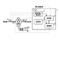
また、変電所Sの構内には、図3に示すように、進相無効電力を供給する電力コンデンサSCや進相無効電力を吸収する分路リアクトルShRが設けられており、系統電圧を調整可能なようになっている。本実施形態に係るVQC1は、系統電圧を基準値に保つと共に送電損失を小さくするべく、変圧器TR−Sの1次側の電圧や無効電力、2次側の電圧、遮断器CB−SA,SBの開閉状態に基づいて、電力コンデンサSCや分路リアクトルShRの遮断器の開閉や変圧器TR−Sにおける負荷時タップ切替器(LTC)のタップ切り替えを行う。
In addition, as shown in FIG. 3, the substation S is provided with a power capacitor SC for supplying the phase reactive power and a shunt reactor ShR for absorbing the phase reactive power so that the system voltage can be adjusted. It is like that. The
VQC1は、日中の電力需要の増加により無効電力が不足している場合、すなわち、変圧器TR−Sの1次側の母線電圧あるいは通過無効電力量が基準値よりも低下した場合には、電力コンデンサSCの遮断器を投入する。これにより、系統電圧の回復が図られる。また、VQC1は、夜間の電力需要の減少により無効電力が過剰な場合、すなわち、変圧器TR−Sの1次側の母線電圧あるいは通過無効電力量が基準値よりも上昇した場合には、分路リアクトルShRの遮断器を投入する。また、VQC1は、変圧器TR−Sの2次側の母線電圧が基準値よりも低下した場合には、変圧器TR−SのLTCを動作させる。 When the reactive power is insufficient due to an increase in power demand during the day, that is, when the bus voltage on the primary side of the transformer TR-S or the amount of passing reactive power is lower than the reference value, VQC1 Turn on the breaker of the power capacitor SC. Thereby, the system voltage is recovered. In addition, VQC1 is divided when the reactive power is excessive due to a decrease in power demand at night, that is, when the bus voltage on the primary side or the passing reactive power amount of the transformer TR-S is higher than the reference value. Turn on the breaker of the road reactor ShR. Moreover, VQC1 operates LTC of transformer TR-S, when the bus-line voltage of the secondary side of transformer TR-S falls from a reference value.
VQC1は、プロセッサやメモリ、入出力インターフェース等によって構成されており
、各種データを演算して各種制御信号を出力する。VQC1は、メモリ上にロードしたプログラムをプロセッサやメモリ、入出力インターフェースが協働して実行することにより、図3に示すように、無効電力検出部2や演算部3、設定部4、制御部5を実現する。無効電力検出部2はその名の通り、変圧器TR−Sの通過無効電力を検出する。また、演算部3は、取得した有効電力Pや無効電力Q、或いは構内遮断器の状態に関する情報等に基づいて各種の演算を行う。設定部4は、VQC1がLTCやSC,ShRの制御に際して用いる、基準となるべき電圧値や無効電力値等に関するデータを提供する。制御部5は、設定部4から与えられるデータに基づいてLTCやSC、ShRを制御する。
The
<VQCが実行する制御の内容>
以下、本実施形態に係るVQC1が実行する制御について説明する。図4は、VQC1が実行する制御のフローチャートである。VQC1は、図4のフローチャートに示す制御を常に実行しており、電力系統の状態に応じたSCやShR、LTCの制御を行う。
<Contents of control executed by VQC>
Hereinafter, control executed by the
(ステップS101)VQC1は、SCやShRの遮断器の開閉状態、LTCのタップ位置の状態、及び変電所Sの母線構成に関する情報を取得する。
(Step S <b> 101) The
(ステップS102)次に、VQC1は、変圧器TR−Sの1次側の電圧Vpや有効電力P(T)、無効電力Q(T)に関する情報を取得する。なお、有効電力P(T)や無効電力Q(T)の代わりに電流Iと位相角θに関する情報を取得して有効電力や無効電力を算出してもよい。有効電力や無効電力は日負荷変動によって変化するため、ここでは有効電力をP(T)と表し、無効電力をQ(T)と表すことで、有効電力および無効電力が時刻Tに依存することを明らかにしている。
(Step S102) Next, the
(ステップS103)次に、VQC1は、ステップS102で取得した各プロセス値(Vp,P(T),Q(T))から、電力コンデンサSCや分路リアクトルShRの最適な投入量(Yr)やLTCの最適な位置(nr)を算出する。
(Step S103) Next, the
ここで、本実施形態に係るVQC1は、ステップS102で取得した各プロセス値に基づいて電力コンデンサSCや分路リアクトルShRの遮断器を開閉したり変圧器TR−Sのタップを切り替えたりするが、電力系統の状態は系統構成や時々刻々と変化する電力潮流に依存する。
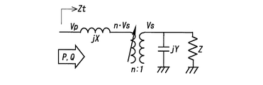
Here, the
図5は、変電所と需要を模擬した簡易なモデル回路である。以下の各数式において、Vpは変電所1次電圧、Vsは変電所2次電圧、Ztは変電所1次側から負荷側を見たインピーダンス、nは変圧器の変圧比率(タップ比)、Xは変電所内の直列リアクタンス、YとZは変電所2次側からみた並列リアクタンスと負荷インピーダンスである。変電所の調相設備もYに含めている。P,Qは変圧器1次側通過有効電力及び無効電力である。 FIG. 5 is a simple model circuit that simulates substations and demand. In the following equations, Vp is the substation primary voltage, Vs is the substation secondary voltage, Zt is the impedance when the load side is viewed from the substation primary side, n is the transformer transformation ratio (tap ratio), X Is the series reactance in the substation, and Y and Z are the parallel reactance and load impedance as seen from the secondary side of the substation. Substation phase adjustment equipment is included in Y. P and Q are transformer primary side active power and reactive power.
このとき、Ztは各変数を用いて次式で表現される。一般的には、Xは正の値であり、無効電力QをゼロにするためにはYが負の値を取ることを条件としている。

ここで最適な自動制御とは、変圧器通過無効電力を規定の範囲内に収め、変圧器の2次側母線電圧を規定の基準値に維持することにあるが、例えば、変圧器1次側通過無効電力をゼロにするには、換言すると、虚数部をゼロにするということは、以下の条件を満たすことになる。
この式から、どのような負荷インピーダンスY,Zをとっても、次式のようにnを制御すればよいことが判る。
また、変圧器の2次側母線電圧を一定に維持するためには、以下の数式が成立することになる。
この式に上記Ztを代入することで次式の条件が得られる。
但し、代入するZtは以下の通りである。
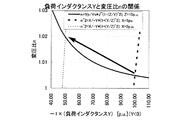
図6は、上記条件式において、Vp(絶対値)=1.0[p.u.]、Vs(絶対値)=1.0[p.u.]、且つX=1.0[p.u.]としたYとnとの関係を示したグラフである。細線は無効電力Qをゼロとする条件式の曲線であり、太線はVs一定を条件とする曲線である。実線はZ=10[p.u.]の場合、点線はZ=8[p.u.]の場合である。太線と細線のそれぞれの交点は最適運用となる条件であり、Z=10[p.u.]において運転点n=1.005、Y=−100[p.u.]が最適となるが、需要が増加してZ=8[p.u.]となれば運転点n=1.008,Y=−64[p.u.]が最適となり、変圧器タップの上昇と並列コンデンサの投入などが必要となる。よって、最適運用となるYとnは、Zの値、つまり電力需要に応じて変化することが判る。 FIG. 6 shows that Vp (absolute value) = 1.0 [p. u. ], Vs (absolute value) = 1.0 [p. u. ] And X = 1.0 [p. u. ] Is a graph showing the relationship between Y and n. A thin line is a curve of a conditional expression in which the reactive power Q is zero, and a thick line is a curve on the condition that Vs is constant. The solid line is Z = 10 [p. u. ], The dotted line is Z = 8 [p. u. ]. Each intersection of a thick line and a thin line is a condition for optimal operation, and Z = 10 [p. u. ], The operating point n = 1.005, Y = -100 [p. u. ] Is optimal, but demand increases and Z = 8 [p. u. ], The operating point n = 1.008, Y = −64 [p. u. ] Is optimal, and it is necessary to raise the transformer tap and insert a parallel capacitor. Therefore, it can be seen that Y and n, which are optimum operations, change according to the value of Z, that is, the power demand.
また、図7は、図6と同様、Vp(絶対値)=1.0[p.u.]、Vs(絶対値)=1.0[p.u.]且つZ=10[p.u.]としたYとnの関係を示すグラフである。実線はVsが一定の曲線であり、点線は無効電力Qをゼロとする条件式の曲線である。点線において太線はX=1[p.u.]とした場合、細線はX=2[p.u.]とした場合の無効電力Qをゼロとする条件式の曲線である。上記変電所Sでは構内に1台の変圧器TR−Sのみを図示しているが、例えば、変電所内において、並列運用する変圧器の台数が遮断器の入切によって変化すれば、Xも変化することになる。 7 is similar to FIG. 6 in that Vp (absolute value) = 1.0 [p. u. ], Vs (absolute value) = 1.0 [p. u. ] And Z = 10 [p. u. ] Is a graph showing the relationship between Y and n. The solid line is a curve with a constant Vs, and the dotted line is a conditional expression curve in which the reactive power Q is zero. In the dotted line, the thick line is X = 1 [p. u. ], X = 2 [p. u. ] Is a conditional expression curve in which the reactive power Q is zero. In the substation S, only one transformer TR-S is shown in the premises. For example, if the number of transformers operated in parallel changes in the substation due to the on / off of the circuit breaker, X also changes. Will do.
例えば、変圧器1台でX=2[p.u.]の場合に、同じ変圧器を2台並列運用すると、X=1[p.u.]となることから、変電所内の系統構成によっても最適運用は影響を受けることが判る。このグラフから、例えばX=1[p.u.]の場合においては、両曲線の交点である運転点n=1.005,Y=−100[p.u.]が最適運用であるが、X=2[p.u.]の場合においては、両曲線の交点である運転点n=1.02,Y=−50[p.u.]が最適運用となり、変圧器タップの上昇と並列コンデンサの投入などが必要となる。最適運用の状態はXの値でも変化することが判る。 For example, X = 2 [p. u. ], When two identical transformers are operated in parallel, X = 1 [p. u. Therefore, it can be seen that the optimum operation is also affected by the system configuration in the substation. From this graph, for example, X = 1 [p. u. ], The operating point n = 1.005, Y = −100 [p. u. ] Is the optimal operation, but X = 2 [p. u. ], The operating point n = 1.02, Y = −50 [p. u. ] Is the optimum operation, and it is necessary to raise the transformer tap and insert a parallel capacitor. It can be seen that the state of optimum operation also changes with the value of X.
上記より、電力系統にとって最適なLTCの切り替えや電力コンデンサSC、分岐リアクトルShRの投入や開放は、系統構成の状態や負荷の潮流状態に依存することが判る。よって、従来から行われているように、代表的な電力潮流のシミュレーションから得た、LTC,SC,ShRの自動制御を行うためのVQCのパターン基準値では、図8に示すように、実際の需要曲線(図8(B)を参照)が、VQCに設定されたパターン基準値が想定している需要曲線(図8(A)を参照)から乖離しているような場合や、系統構成が変更されているような場合に、最適なLTCの切り替えやSC,ShRの投入解放の運用が行われ得ないことを意味する。 From the above, it can be seen that the switching of the LTC that is optimal for the power system and the introduction and release of the power capacitor SC and the branch reactor ShR depend on the state of the system configuration and the power flow state of the load. Therefore, as shown in FIG. 8, the VQC pattern reference value for automatic control of LTC, SC, and ShR obtained from a typical power flow simulation as shown in FIG. When the demand curve (see FIG. 8B) deviates from the assumed demand curve (see FIG. 8A) of the pattern reference value set in the VQC, or when the system configuration is This means that when it is changed, optimal LTC switching or SC / ShR input / release operation cannot be performed.
例えば、従来からあるVQCのように設定されている電圧パターン基準値が一定な状態において、図1に示した系統構成が変更された場合を考える。需要家Aの昼の消費電力Paが5.0[p.u.]で無効電力Qaが1.0[p.u.]、需要家Bの昼の消費電力Pbが5.0[p.u.]で無効電力Qbが4.0[p.u.]であり、夜間は共に半減するものとする。なお、需要家Aの消費電力Paと無効電力Qaとは、供給する送電線以下で消費される有効電力と無効電力であり、送電線以下の系統内に設けられた調相設備の稼動や系統構成の切り替えに伴う需要変動に起因するものも含む。 For example, consider a case where the system configuration shown in FIG. 1 is changed in a state where the voltage pattern reference value set as in the conventional VQC is constant. Consumer A's daytime power consumption Pa is 5.0 [p. u. ], The reactive power Qa is 1.0 [p. u. ], The consumer's B daytime power consumption Pb is 5.0 [p. u. ], The reactive power Qb is 4.0 [p. u. ] And both at night will be halved. The power consumption Pa and reactive power Qa of the customer A are active power and reactive power consumed below the transmission line to be supplied. The operation and system of the phase adjusting equipment provided in the system below the transmission line Including those caused by fluctuations in demand due to compositional changes.
この場合、変電所SのVQCは、昼の有効電力Psが10.0[p.u.]で無効電力Qsが5.0[p.u.]、夜の有効電力Psが5.0[p.u.]で無効電力Qsが2.5[p.u.]という設定のパターン基準値に基づいて無効電力制御と変圧比の制御を行うことになる。ところが、例えば、CB−SBが開放されたりすることにより、系統構成が図9のように変更されて、変電所Sから需要家Bへの送電が無くなると、昼の有効電力Psは夜の有効電力と同じ値5.0[p.u.]で無効電力Qsは1.0[p.u.]となることから、VQCの制御パターンが系統構成の変更によって変化してしまい、この制御パターンでは系統構成変更後に最適なLTCやSC、ShRの自動制御が行えなくなることが判る。 In this case, the VQC of the substation S has a daytime active power Ps of 10.0 [p. u. ], The reactive power Qs is 5.0 [p. u. ], The effective power Ps at night is 5.0 [p. u. ], The reactive power Qs is 2.5 [p. u. ], The reactive power control and the transformation ratio control are performed based on the pattern reference value set. However, for example, when the CB-SB is opened and the system configuration is changed as shown in FIG. 9 and power transmission from the substation S to the customer B is lost, the daytime effective power Ps becomes effective at night. Same value as power 5.0 [p. u. ], The reactive power Qs is 1.0 [p. u. Therefore, it can be seen that the VQC control pattern changes due to the change in the system configuration, and in this control pattern, the optimum LTC, SC, and ShR automatic control cannot be performed after the system configuration change.
ここで、系統状態を把握するための方法としては、VQCを集中制御型とする方策も考えられる。但し、この場合は、各変電所に設置される端末としてのVQCと、中央給電指令所等に設置されるVQCの中央装置との間で信頼性の高い電力用通信手段を構築する必要がある。また、中央装置においても故障時を想定して冗長性を持たせた複数台運用が必要である。加えて、電力系統の設備は常に更新されており、更新に応じたVQCのソフトウエアの書き換えなどのメンテナンスも欠かせない。 Here, as a method for grasping the system state, a method of making the VQC a centralized control type is also conceivable. However, in this case, it is necessary to construct a highly reliable power communication means between the VQC as a terminal installed in each substation and the VQC central device installed in the central power supply command station or the like. . In addition, it is necessary to operate a plurality of units with redundancy in the central unit assuming a failure. In addition, the power system equipment is constantly updated, and maintenance such as rewriting of VQC software corresponding to the update is indispensable.
そこで、本実施形態に係るVQC1は、このような集中制御型を採らないものの、自律分散制御を指向するものであり、具体的には、VQCの制御対象は従来通りLTCやSC,ShRのみとしつつ、図10に示すように、従来例ではVQCの情報認識範囲が同一構内にある変圧器の1次側電圧や無効電力、2次側の電圧だけであったものを、本実施形態に係るVQCでは同一構内にある遮断器の開閉状態にまで拡大し、変電所Sに需要家Aや需要家Bへの送電線が接続されているか否かまで含めることとする。VQCの制御対象範囲は従来通りとすることで、既存のVQCを利用でき、集中制御型の通信設備や中央装置の新設が不要である。
Therefore, although the
上述したように、最適運用となるLTCやSC、ShRの制御量は、電力需要の変動、或いは並列運用する構内変圧器の台数や下位変電所へ繋がる線路の接続状態といった変電所内の系統構成によって影響を受けるが、本実施形態に係るVQC1は、情報認識範囲を図10の「実施例」として示す範囲に拡大することで上記条件式におけるXやZを特定し、各条件式から得られるグラフの交点から最適運用となるYおよびnを算出できる。VQC1は、算出したYおよびnを、SCやShR、LTCの最適な制御量(nr,Yr)として決定する。
As described above, the amount of control for LTC, SC, and ShR that is optimal operation depends on the system configuration in the substation, such as fluctuations in power demand, or the number of on-site transformers operated in parallel and the connection status of the lines leading to the substation. Although affected, the
(ステップS104)次に、VQC1は、ステップS101で取得したSCやShRの遮断器の開閉状態やLTCのタップ位置に関する情報に基づく、現状のSCやShRの投入量(Y)及びLTCの位置(n)と、ステップS103で算出したSCやShR、LTCの最適な制御量(nr,Yr)とを比較する。VQC1は、SCやShR、LTCの調整が不要な場合、すなわち、現状の制御量と最適な制御量とが一致しており、n,Yに過不足が無ければ、再びステップS102以降の処理を実行する。一方、VQC1は、SCやShR、LTCの調整が必要な場合、すなわち、現状の制御量(n,Y)と最適な制御量(nr,Yr)とが一致しておらず、n,Yに過不足が有れば、ステップS105以降の処理を実行する。
(Step S104) Next, the
(ステップS105)VQC1は、ステップS105でn,Yに過不足が有ると判定した場合、現状のSC,ShR、LTCの制御量(n,Y)が最適な制御量(nr,Yr)と一致するように、SCやShRの遮断器の投入や開放、或いはLTCのタップ位置の変更を行う。そして、VQC1は、再びステップS101以降の処理を実行する。 (Step S105) When VQC1 determines that there are excess and deficiencies in n and Y in step S105, the current control amounts (n, Y) of SC, ShR, and LTC match the optimal control amounts (nr, Yr). As described above, the circuit breaker of SC or ShR is turned on or opened, or the tap position of the LTC is changed. And VQC1 performs the process after step S101 again.
<VQCの効果>
以上、本実施形態に係るVQC1によれば、情報認識範囲を拡張することで電力需要の変動や変電所内の系統構成から最適運用となるYおよびnを数式から算出し、算出した制御量に基づいてSCやShR、LTCを動かしているので、最適な電圧及び無効電力の制御が可能となる。
<Effect of VQC>
As described above, according to the
<変形例1>
なお、上記VQC1は次のように変形してもよい。例えば、特定の変電所に設置されているVQCの情報認識範囲は、必ずしも隣接する下位の変電所に設置されているVQCの情報認識範囲に接しているわけではない。ここで上位と下位は、送電線を流れる電力潮流方向が上位から下位となる向きに定義している。これは、先のモデル等価回路において説明したとおり、VQCは変電所から負荷側を見ていることに依る。VQCが負荷側に対して最適な制御を行うためには電力潮流の向きが重要な情報要素となり、この意味において、変電所から電力潮流が出て行く送電線接続状況だけではなく、送電線の先において受電している変電所の電力潮流や系統状況を把握し、隣接する変電所の負荷側のインピーダンスと送電線の電力潮流状況を認識する必要がある。
<
The VQC1 may be modified as follows. For example, the information recognition range of a VQC installed at a specific substation does not necessarily touch the information recognition range of a VQC installed at an adjacent substation. Here, upper and lower are defined such that the direction of power flow through the transmission line is from upper to lower. This is because the VQC looks at the load side from the substation as described in the previous model equivalent circuit. The direction of the power flow is an important information element for the VQC to perform optimal control on the load side. In this sense, not only the transmission line connection status where the power flow comes from the substation, but also the transmission line It is necessary to grasp the power flow and system status of the substation receiving power, and to recognize the load-side impedance of the adjacent substation and the power flow status of the transmission line.
例えば、図1の変電所G,T,Uの関係において説明すると、最適な制御を行うためには、送電線が途中で分岐している場合に、変電所Gの下位に変電所TやUが接続されているのか、また、その場合の電力潮流の向きは変電所Gからみて負荷側となる向きであるのかも含めて、変電所GのVQCは情報を認識する必要がある。例えば、変電所Uが負荷側に含まれない場合、すなわち、電力潮流が変電所GとUから変電所Tに向いている場合、これを変電所GのVQCが認識するためには、隣接する変電所T,Uの情報が欠かせない。これは、送電線で消費される無効電力も送電線の電力潮流状況に応じて変化するために、各送電線のブランチの電力潮流状況を推定する必要があることによる。なお、各送電線のブランチの電力潮流状況は、隣接する送電設備の系統定数(線路インピーダンス)が既知であるため、推定可能である。 For example, in the relationship between the substations G, T, and U in FIG. 1, in order to perform optimal control, when the transmission line is branched halfway, the substations T and U are subordinate to the substation G. In addition, the VQC of the substation G needs to recognize information including whether or not the power flow is connected and the direction of the power flow in that case is the direction of the load side when viewed from the substation G. For example, when the substation U is not included on the load side, that is, when the power flow is directed from the substations G and U to the substation T, in order for the VQC of the substation G to recognize this, it is adjacent Information on substations T and U is essential. This is because the reactive power consumed in the transmission line also changes in accordance with the power flow situation of the transmission line, so it is necessary to estimate the power flow situation of the branch of each transmission line. In addition, the power flow situation of the branch of each power transmission line can be estimated because the system constant (line impedance) of the adjacent power transmission equipment is known.
そこで、図11の表に基づき、VQC1に隣接する変電所の情報を認識させる変形例を説明する。図11の表の下段においては、上位の変電所から負荷(需要)側を見たときの記号を「>」で表し、その隣接変電所名を括弧で囲んでいる。負荷側に位置しない上位変電所は、その括弧の中において「*」と表現する。電力潮流方向は電流値から特定し、供給先の変電所あるいは需要家の有無は変電所内の遮断器の開閉状態から特定する。VQC1は、このように情報を管理することにより、負荷側ではないが情報送信先が存在することを認識できる。情報の送信は、送電線保護継電器用の伝送回線などを経由して行なう。
Therefore, a modified example for recognizing information of a substation adjacent to the
例えば、図11の表の「系統構成1」において、変電所SのVQC1は、需要家Aの送電線S−Aと需要家Bの送電線S−Bを認識しており、送電線S−AとS−Bの線路インピーダンスによる無効電力消費量を含めて集約した需要家AとBの負荷インピーダンスを情報「S>(*,A,B)」として認識する。図11の「系統構成1」では変電所Gが変電所Sの上流側に位置しており、負荷側には位置していないため、情報「S>(*,A,B)」には「G」が示されていないが、変電所Gは系統に連系されているため、電力潮流の方向によっては変電所Gが変電所Sよりも負荷側に位置する可能性もあるため、変電所Gを「*」で表している。電力潮流が逆向きになれば、「*」が「G」になる。変電所Gは、負荷側として変電所H、S、TそしてUを下位の変電所として持つことから、変電所GのVQC1は、送電線G−Sの線路インピーダンスと変電所Sの1次側から負荷側を見た負荷インピーダンスによる無効電力消費量を含めて集約した負荷インピーダンスをはじめとして、送電線G−T−Uや送電線G−Hを並列回路とするすべてを集約した負荷インピーダンスを情報「G>(H,S,T,U)」として認識し、最適制御を行う。これにより、算出されるSCやShR、LTCの制御量がより適正な値になるので、最適な電圧及び無効電力の制御が実現される。
For example, in the “
図11の表の「系統構成2」は、「系統構成1」の電力系統の系統切り替えを実施した例である。需要家Bは変電所Sから変電所Tに、変電所Uは変電所Gから変電所Hに系統を切り替えている。この系統構成で各VQC1が認識する情報としては、「系統構成1」では[G>(H,S,T,U), H>(*,*,R), S>(*,A,B), T>(*,*,*,C), U>(*,*,D), R>(*,E)]であったものが、「系統構成2」では[G>(H,S,T,*), H>(*,U,R), S>(*,A,*), T>(*,*,B,C), U(*,*,D), R(*,E)]に変化する。
“
更には、「系統構成1」において送電線G−Hと送電線H−Rの各電力潮流方向が逆転した場合には、「系統構成3」のようになり、先の情報は[G>(*,S,T,*), H>(G,U,*), R>(H,E), S>(*,A,*), T>(*,*,B,C), U>(*,*,D)]に変更となる。
Further, when the power flow directions of the transmission line GH and the transmission line HR are reversed in the “
なお、情報認識範囲は限定的であり、例えば「系統構成3」において、変電所Rが変電所Gの状況を認識することはない。認識させるためには、先に述べたとおり、集中型のように変電所Gから変電所Rに向けての情報伝達手段が必要になるが、この場合、例えば、変電所間の線路インピーダンスが設備更新などで変更され若しくは新設されるような場合には、各VQCに登録される情報をすべて書き換える必要性が出てくる。 Note that the information recognition range is limited. For example, in “system configuration 3”, the substation R does not recognize the status of the substation G. In order to recognize the information, as described above, information transmission means from the substation G to the substation R is required as in the centralized type. In this case, for example, the line impedance between the substations is the equipment. When it is changed or updated by updating, it is necessary to rewrite all information registered in each VQC.
<変形例2>
なお、上記VQC1は次のように変形してもよい。図12は、変形例に係るVQC1が図4の処理フローと並列に実行する別処理フローである。以下、本変形例に係るVQC1が実行する処理について説明する。
<
The VQC1 may be modified as follows. FIG. 12 is another processing flow executed by the
(ステップS201)VQC1は、上述したステップS102の処理を実行後、取得したプロセス値、すなわち、有効電力Pの履歴記録P(T)や無効電力Qの履歴記録Q(T)、nやYを基に、有効電力と無効電力との相関関係であるPQ相関を作成する。PQ相関は、データ列によって特定されたものであってもよいし数式によって特定されたものであってもよい。
(Step S201) After executing the process of Step S102 described above, the
(ステップS202)次に、VQC1は、送電線保護継電器用の伝送回線を経由して送られる下位の変電所や需要家からPQ相関を取得する。
(Step S202) Next, the
例えば、図13に示すように、送電線A−Bと繋がっているA変電所のVQCが、有効電力Pが(Pa+Pb)、無効電力Qが(Qa+Qb)となるPQ相関Q=αab×P+βabに基づいて電圧・無効電力制御を行っていたものとする。αabはPに対する比例係数、βabは送電線A−Cに固有の無効電力成分と送電線A−Bに固有の無効電力成分とA変電所に固有の無効電力成分の和であり、有効電力成分に依存しない。ここで、系統構成の変更によって送電線A−BがB変電所からの送電系統となった場合、従来例に係るVQCは各送電線のPQ相関を知り得ない状況から、(Pa+Pb)が最大電力需要断面とした上で、前記PQ相関をQ=αa’×P+βa’、αa’=αab、βa’= βa
b×Pa/(Pa+Pb)+βcとして処理していた。なお、βcは系統変更などに依らない一定の無効電力成分である。しかしながら、本来は、各送電線の実績に応じて求まるPQ相関式Q=αa×P+βa+QcとQ=αb×P+βbに基づき、A変電所ではPQ相関Q=αa×P+βaに基づいて電圧・無効電力制御を行うべきであり、図14のグラフに示すように、必ずしも直線の傾きαa’は実績の値αaに一致せず、また、A変電所の有効電力Paに応じて従来方式のVQCが認識する無効電力Qa’も実績の値Qaと異なることとなり、系統構成変更前に参照していた無修正のPQ相関では適切な電圧・無効電力制御が実現できないことが判る。なお、PQ相関の関係においては、QがPの1次式
であるとして説明したが、多項式(n次式)であっても良い。
For example, as shown in FIG. 13, the VQC of the A substation connected to the transmission line AB is PQ correlation Q = αab × P + βab where the active power P is (Pa + Pb) and the reactive power Q is (Qa + Qb). It is assumed that voltage / reactive power control has been performed based on this. αab is a proportional coefficient with respect to P, βab is the sum of the reactive power component specific to the transmission line A-C, the reactive power component specific to the transmission line AB, and the reactive power component specific to the A substation, and the active power component Does not depend on. Here, when the transmission line A-B becomes a transmission system from the B substation due to a change in the system configuration, the VQC according to the conventional example has a maximum (Pa + Pb) because the PQ correlation of each transmission line cannot be known. In the power demand section, the PQ correlation is expressed as Q = αa ′ × P + βa ′, αa ′ = αab, βa ′ = βa
It processed as b * Pa / (Pa + Pb) + (beta) c. Βc is a constant reactive power component that does not depend on a system change or the like. However, based on the PQ correlation equation Q = αa × P + βa + Qc and Q = αb × P + βb obtained according to the actual performance of each transmission line, the voltage / reactive power control is performed based on the PQ correlation Q = αa × P + βa in the A substation. As shown in the graph of FIG. 14, the slope αa ′ of the straight line does not necessarily coincide with the actual value αa, and the conventional VQC recognizes according to the effective power Pa of the A substation. The reactive power Qa ′ is also different from the actual value Qa, and it is understood that appropriate voltage / reactive power control cannot be realized by the uncorrected PQ correlation referred to before the system configuration change. In the relationship of PQ correlation, Q is a linear expression of P. However, a polynomial expression (n-order expression) may be used.
(ステップS203)そこで、本実施形態に係るVQC1は、下位の変電所あるいは需要家から送られたPQ相関に基づいて、自身のPQ相関を修正する。
(Step S203) Therefore, the
(ステップS204)また、VQC1は、修正したPQ相関を上位変電所である変電所Gへ送信する。 (Step S204) Moreover, VQC1 transmits the corrected PQ correlation to the substation G which is a high-order substation.
(ステップS205)VQC1は、修正済のPQ相関と規定の日負荷変動曲線とに基づいて、t時間経過後の有効電力Pと無効電力Qを推定する。ここで、時間tとは、有効電力Pと無効電力Qの推定結果に基づくSC,ShRの投入開放やLTCの切り替えを現時点で実行することが妥当であるのか否かの判定のための設定時間であり、電圧・無効電力制御を行う機器の作動回数を削減する目的で設定される時間である。VQC1は、規定の日負荷変動曲線に基づいてt時間経過後の有効電力Pを推定する。そして、VQC1は、推定した有効電力Pと修正済のPQ相関との関係に基づいて、t時間経過後の無効電力Qを推定する。
(Step S205) The
(ステップS206)VQC1は、推定したt時間経過後の有効電力Pと無効電力Qに基づいて、SCやShR、LTCの最適な制御量(nr’,Yr’)を算出する。 (Step S206) VQC1 calculates the optimal control amount (nr ', Yr') of SC, ShR, and LTC based on the active power P and reactive power Q after elapse of the estimated t time.
以上に示した一連の処理フロー(S201〜S206)が実行されることによって算出されたt時間後の最適な制御量(nr’,Yr’)は、以下の処理によってVQC1の制御フローに反映される。 The optimal control amount (nr ′, Yr ′) after time t calculated by executing the above-described series of processing flows (S201 to S206) is reflected in the control flow of VQC1 by the following processing. The
図15は、本変形例に係るVQC1が実行する制御のフローチャートであり、図4に示したフローチャートを改変したものである。図4に示したフローチャートとの相違点は、新たなステップS106をステップS104とステップS105との間に挿入した点であり、その他のステップで実行される処理の内容は既述のものと同様なため、それらの詳細な説明は省略する。
FIG. 15 is a flowchart of control executed by the
(ステップS106)本変形例に係るVQC1は、ステップS104で肯定判定を下した場合、ステップS101で取得したSCやShRの遮断器の開閉状態、LTCのタップ位置に関する情報に基づく現状のSC,ShR、LTCの制御量(n,Y)と、上記別フローのステップS206で算出したt時間経過後の最適な制御量(nr’,Yr’)とを比較する。
(Step S106) When the
VQC1は、t時間経過後にはSCやShR、LTCの調整が不要と推定される場合、すなわち、現状の制御量(n,Y)とt時間経過後の最適な制御量(nr’,Yr’)とが一致しており、n,Yに過不足が無ければ、再びステップS102以降の処理を実行する。 When VQC1 is estimated that adjustment of SC, ShR, and LTC is unnecessary after the elapse of time t, that is, the current control amount (n, Y) and the optimal control amount (nr ′, Yr ′) after elapse of t time. ) Match, and if there is no excess or deficiency in n and Y, the processing after step S102 is executed again.
一方、VQC1は、t時間経過後もSCやShR、LTCの調整が必要と推定される場合、すなわち、現状の制御量(n,Y)とt時間経過後の最適な制御量(nr’,Yr’)とが一致しておらず、n,Yに過不足が有れば、最適な制御量(nr’,Yr’)に基づくステップS105の処理を実行する。この場合、VQC1は、上述したステップS105の処理において、現状のSC,ShR、LTCの制御量(n,Y)がt時間経過後の最適な制御量(nr’,Yr’)と一致するように、SCやShRの遮断器の投入や開放、或いはLTCのタップ位置の変更を行うことになる。そして、VQC1は、再びステップS101以降の処理を実行する。 On the other hand, when VQC1 is estimated to require adjustment of SC, ShR, and LTC even after the elapse of time t, that is, the current control amount (n, Y) and the optimal control amount (nr ′, If Yr ′) does not match and there is an excess or deficiency in n and Y, the process of step S105 based on the optimal control amount (nr ′, Yr ′) is executed. In this case, in the process of step S105 described above, VQC1 causes the current SC, ShR, and LTC control amounts (n, Y) to match the optimal control amounts (nr ′, Yr ′) after t time has elapsed. In addition, the SC or ShR circuit breaker is turned on or opened, or the LTC tap position is changed. And VQC1 performs the process after step S101 again.
本変形例に係るVQC1は、このように下位変電所のPQ相関を記憶しておき、系統切り替えやPの変化に応じて必要なQを予見することで、不要なタップ操作や調相設備の入切を無くして機器の操作回数を減らし、予測制御を可能にしている。
The
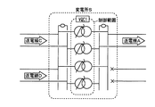
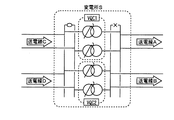
なお、本実施形態に係るVQCは、複数の変圧器を有する変電所にも設置できる。この場合、本実施形態に係るVQCは、例えば、図16に示すように、同一変電所内に1つのみ設置し、各変圧器を並列運用により1つのユニットとして取り扱い、送電線Aの代表的な電力潮流状態を想定して最適制御を行ってもよい。 Note that the VQC according to the present embodiment can also be installed in a substation having a plurality of transformers. In this case, for example, as shown in FIG. 16, only one VQC according to this embodiment is installed in the same substation, and each transformer is handled as one unit by parallel operation. Optimal control may be performed assuming a power flow state.
また、本実施形態に係るVQCは、例えば、図17に示すように、同一変電所内に2つのVQCを設置し、VQC1が制御する変圧器群とVQC2が制御する変圧器群とを分けた分割系統として、VQC1が送電線Aを、VQC2が送電線Bを制御してもよい。
In addition, for example, as shown in FIG. 17, the VQC according to the present embodiment has two VQCs installed in the same substation, and is divided into a transformer group controlled by VQC1 and a transformer group controlled by VQC2. As a system, the
なお、電力潮流が反転し、例えば、図18に示すような状態になれば、VQC1の制御範囲はVQC2の制御範囲の上位に位置することになるため、同じ変電所Sの構内にありながら2つの変電所を含むように、各VQCが隣接するVQCと協調をとって制御を行うことになる。 Note that if the power flow is reversed and, for example, the state shown in FIG. 18 is reached, the control range of VQC1 is positioned higher than the control range of VQC2, and thus 2 while being in the same substation S Each VQC performs control in cooperation with the adjacent VQC so as to include two substations.
1・・VQC
2・・無効電力検出部
3・・演算部
4・・設定部
5・・制御部
1. VQC
2. Reactive power detection unit 3. Calculation unit 4. Setting unit 5. Control unit
Claims (3)
前記所定変電所および該所定変電所よりも下流側の回路を模擬した回路モデルに、該所定変電所の上流側の電圧と該所定変電所が供給する有効電力および無効電力を入力し、該所定変電所の下流側の電圧と該所定変電所が供給する無効電力が規定の条件を満たすこととなる前記変圧器のタップと前記調相設備の制御量を算出する演算部と、
前記演算部が決定した制御量に基づいて前記調相設備と前記タップとを制御する制御部と、を備える、
電圧無効電力制御装置。 A voltage reactive power control device installed at a predetermined substation having phase adjusting equipment and a transformer,
A circuit model simulating the predetermined substation and a circuit downstream from the predetermined substation is inputted with an upstream voltage of the predetermined substation and active power and reactive power supplied by the predetermined substation, A calculation unit that calculates a control amount of the tap of the transformer and the phase-adjusting equipment, in which the voltage on the downstream side of the substation and the reactive power supplied by the predetermined substation satisfy a specified condition;
A control unit that controls the phase adjusting equipment and the tap based on a control amount determined by the arithmetic unit;
Voltage reactive power control device.
請求項1に記載の電圧無効電力制御装置。 The arithmetic unit corrects the parameters of the circuit model based on the state of a switch in the predetermined substation.
The voltage reactive power control apparatus according to claim 1.
請求項1または2に記載の電圧無効電力制御装置。 The calculation unit obtains a correlation between active power and reactive power at the supply destination from a supply destination adjacent to the predetermined substation in the system, and acquires the correlation and active power and reactive power at the predetermined substation. Estimating the correlation after the lapse of a predetermined time based on the correlation, and calculating the control amount of the tap of the transformer and the phase adjusting equipment from the estimation result and the circuit model,
The voltage reactive power control apparatus according to claim 1 or 2.
Priority Applications (1)
| Application Number | Priority Date | Filing Date | Title |
|---|---|---|---|
| JP2011034378A JP2012175778A (en) | 2011-02-21 | 2011-02-21 | Voltage reactive power control device |
Applications Claiming Priority (1)
| Application Number | Priority Date | Filing Date | Title |
|---|---|---|---|
| JP2011034378A JP2012175778A (en) | 2011-02-21 | 2011-02-21 | Voltage reactive power control device |
Publications (1)
| Publication Number | Publication Date |
|---|---|
| JP2012175778A true JP2012175778A (en) | 2012-09-10 |
Family
ID=46978151
Family Applications (1)
| Application Number | Title | Priority Date | Filing Date |
|---|---|---|---|
| JP2011034378A Withdrawn JP2012175778A (en) | 2011-02-21 | 2011-02-21 | Voltage reactive power control device |
Country Status (1)
| Country | Link |
|---|---|
| JP (1) | JP2012175778A (en) |
Cited By (6)
| Publication number | Priority date | Publication date | Assignee | Title |
|---|---|---|---|---|
| CN104753066A (en) * | 2015-04-16 | 2015-07-01 | 合肥工业大学 | Parameter fitting-based voltage controlling method for active distribution feeders |
| CN108242811A (en) * | 2018-03-09 | 2018-07-03 | 广东电网有限责任公司汕头供电局 | A kind of alternating current-direct current paired running receiving-end system VQC control methods |
| US10079501B2 (en) | 2013-02-08 | 2018-09-18 | Nec Corporation | Battery control device, battery control system, battery control method, and recording medium |
| JP2018152935A (en) * | 2017-03-10 | 2018-09-27 | 三菱電機株式会社 | Electric power system state estimation device |
| US10790667B2 (en) | 2015-11-20 | 2020-09-29 | Hitachi, Ltd. | Voltage/reactive power control apparatus, method, and voltage/reactive power control system |
| WO2021024424A1 (en) * | 2019-08-07 | 2021-02-11 | 三菱電機株式会社 | Power system state estimation device and power system state estimation method |
-
2011
- 2011-02-21 JP JP2011034378A patent/JP2012175778A/en not_active Withdrawn
Cited By (9)
| Publication number | Priority date | Publication date | Assignee | Title |
|---|---|---|---|---|
| US10079501B2 (en) | 2013-02-08 | 2018-09-18 | Nec Corporation | Battery control device, battery control system, battery control method, and recording medium |
| US10784702B2 (en) | 2013-02-08 | 2020-09-22 | Nec Corporation | Battery control device, battery control system, battery control method,and recording medium |
| CN104753066A (en) * | 2015-04-16 | 2015-07-01 | 合肥工业大学 | Parameter fitting-based voltage controlling method for active distribution feeders |
| US10790667B2 (en) | 2015-11-20 | 2020-09-29 | Hitachi, Ltd. | Voltage/reactive power control apparatus, method, and voltage/reactive power control system |
| JP2018152935A (en) * | 2017-03-10 | 2018-09-27 | 三菱電機株式会社 | Electric power system state estimation device |
| CN108242811A (en) * | 2018-03-09 | 2018-07-03 | 广东电网有限责任公司汕头供电局 | A kind of alternating current-direct current paired running receiving-end system VQC control methods |
| WO2021024424A1 (en) * | 2019-08-07 | 2021-02-11 | 三菱電機株式会社 | Power system state estimation device and power system state estimation method |
| JPWO2021024424A1 (en) * | 2019-08-07 | 2021-11-04 | 三菱電機株式会社 | Power system state estimation device and power system state estimation method |
| JP7055249B2 (en) | 2019-08-07 | 2022-04-15 | 三菱電機株式会社 | Power system state estimation device and power system state estimation method |
Similar Documents
| Publication | Publication Date | Title |
|---|---|---|
| CN102239645B (en) | Electrical power network management method and device | |
| US7729810B2 (en) | Electrical power distribution control systems and processes | |
| Uma et al. | Adaptive overcurrent protection scheme coordination in presence of distributed generation using radial basis neural network | |
| JP2012175778A (en) | Voltage reactive power control device | |
| Lin et al. | Adaptive overcurrent protection for microgrids in extensive distribution systems | |
| CN105453365B (en) | Voltage monitoring control device and voltage-operated device | |
| JP5389303B1 (en) | Distribution system voltage control system and voltage control apparatus | |
| KR102325452B1 (en) | Methods and apparatus for detecting and correcting instabilites within a power distribution system | |
| JP2016036252A (en) | Distribution system voltage control system, distribution system voltage control method, centralized voltage control device, and local voltage control device | |
| JP5147739B2 (en) | Distribution system ground fault protection system, distribution system ground fault protection method, program | |
| Verayiah et al. | Review of under-voltage load shedding schemes in power system operation | |
| Rehtanz et al. | A new wide area protection system | |
| US20210257825A1 (en) | Method and apparatus for preventing same building solar panel produced voltage spikes on a neighbor's electric utility service | |
| US8817444B2 (en) | Control arrangement | |
| CN115940165A (en) | A phase shifter control method and system for realizing power flow control between transformers | |
| JP5191245B2 (en) | Distribution line compensation reactor automatic control system | |
| Skok et al. | System integrity protection schems for future power transmission system using synchrophasors | |
| KR101926308B1 (en) | Distribution automation system having dispersion generation | |
| KR101926306B1 (en) | Distribution Automation System | |
| CA2649838C (en) | Electrical power distribution control systems and processes | |
| Yip et al. | Dynamic thermal rating and active control for improved distribution network utilisation | |
| Allen | Effects of wide-area control on the protection and operation of distribution networks | |
| KR101926307B1 (en) | Control method of distribution Automation System | |
| JP6848234B2 (en) | Voltage monitoring and control device | |
| CN121192716B (en) | A control system for a multi-voltage bus hybrid microgrid |
Legal Events
| Date | Code | Title | Description |
|---|---|---|---|
| A300 | Withdrawal of application because of no request for examination |
Free format text: JAPANESE INTERMEDIATE CODE: A300 Effective date: 20140513 |