JP2012176331A - Three-dimensional rotating mechanism, and ball mill and kneading apparatus with the same - Google Patents
Three-dimensional rotating mechanism, and ball mill and kneading apparatus with the same Download PDFInfo
- Publication number
- JP2012176331A JP2012176331A JP2009169511A JP2009169511A JP2012176331A JP 2012176331 A JP2012176331 A JP 2012176331A JP 2009169511 A JP2009169511 A JP 2009169511A JP 2009169511 A JP2009169511 A JP 2009169511A JP 2012176331 A JP2012176331 A JP 2012176331A
- Authority
- JP
- Japan
- Prior art keywords
- frame
- fixed
- rotation
- shaft
- rotating
- Prior art date
- Legal status (The legal status is an assumption and is not a legal conclusion. Google has not performed a legal analysis and makes no representation as to the accuracy of the status listed.)
- Pending
Links
Images

Classifications
-
- B—PERFORMING OPERATIONS; TRANSPORTING
- B02—CRUSHING, PULVERISING, OR DISINTEGRATING; PREPARATORY TREATMENT OF GRAIN FOR MILLING
- B02C—CRUSHING, PULVERISING, OR DISINTEGRATING IN GENERAL; MILLING GRAIN
- B02C17/00—Disintegrating by tumbling mills, i.e. mills having a container charged with the material to be disintegrated with or without special disintegrating members such as pebbles or balls
- B02C17/10—Disintegrating by tumbling mills, i.e. mills having a container charged with the material to be disintegrated with or without special disintegrating members such as pebbles or balls with one or a few disintegrating members arranged in the container
-
- B—PERFORMING OPERATIONS; TRANSPORTING
- B01—PHYSICAL OR CHEMICAL PROCESSES OR APPARATUS IN GENERAL
- B01F—MIXING, e.g. DISSOLVING, EMULSIFYING OR DISPERSING
- B01F29/00—Mixers with rotating receptacles
- B01F29/10—Mixers with rotating receptacles with receptacles rotated about two different axes, e.g. receptacles having planetary motion
-
- B—PERFORMING OPERATIONS; TRANSPORTING
- B02—CRUSHING, PULVERISING, OR DISINTEGRATING; PREPARATORY TREATMENT OF GRAIN FOR MILLING
- B02C—CRUSHING, PULVERISING, OR DISINTEGRATING IN GENERAL; MILLING GRAIN
- B02C17/00—Disintegrating by tumbling mills, i.e. mills having a container charged with the material to be disintegrated with or without special disintegrating members such as pebbles or balls
- B02C17/18—Details
- B02C17/24—Driving mechanisms
Landscapes
- Engineering & Computer Science (AREA)
- Food Science & Technology (AREA)
- Chemical & Material Sciences (AREA)
- Chemical Kinetics & Catalysis (AREA)
- Mixers With Rotating Receptacles And Mixers With Vibration Mechanisms (AREA)
- Crushing And Grinding (AREA)
- Accessories For Mixers (AREA)
Abstract
【課題】応用範囲の広い三次元回転機構を提供する。
【解決手段】第1枠体3と、当該第1枠体の枠内に配した第2枠体9の回転に加え、当該第2枠体の枠内に配した被回転体15を、当該第2枠体の回転に従動して、第3回転軸の回りで回転させることによって3軸三次元回転機構を構成する。第2枠体は第1枠体の回転に従動させる。被回転体には3軸回転による遠心力が作用するので、被回転体とその収容物が一体回転する、いわゆる供回りを抑制することができるので、ボールミルに好適である等応用範囲が広い。
【選択図】図1A three-dimensional rotation mechanism having a wide application range is provided.
In addition to the rotation of a first frame 3 and a second frame 9 arranged in the frame of the first frame, a rotated body 15 arranged in the frame of the second frame A three-axis three-dimensional rotation mechanism is configured by rotating around the third rotation axis following the rotation of the second frame. The second frame is driven by the rotation of the first frame. Since the centrifugal force due to the three-axis rotation acts on the rotated body, so-called rotation in which the rotated body and its accommodation rotate together can be suppressed, so that the application range is wide, such as being suitable for a ball mill.
[Selection] Figure 1
Description
本発明は、三次元回転機構及びそれを備えたボールミル及び混練装置に関する。 The present invention relates to a three-dimensional rotation mechanism, a ball mill including the same, and a kneading apparatus.
三次元回転機構を備えた装置として、特許文献1に記載されたクリノスタット装置がある。このクリノスタット装置が備える三次元回転機構(以下、「従来の回転機構」という)は、第1枠体と、当該第1枠体を第1回転軸の回りで回転させる第1枠体用駆動機構と、当該第1枠体の枠内に配した第2枠体と、当該第2枠体を、当該第1枠体の回転に従動して、当該第1回転軸と直交する第2回転軸の回りで回転させる第1従動機構と、によって構成されている。すなわち、従来の回転機構は、第1の回転軸と第2の回転軸の2軸回転するように構成されている。上記以外のクリノスタット装置も、同じく2軸回転するように構成されている(特許文献2,3参照)。 As an apparatus provided with a three-dimensional rotation mechanism, there is a clinostat apparatus described in Patent Document 1. A three-dimensional rotation mechanism (hereinafter referred to as “conventional rotation mechanism”) provided in the clinostat device includes a first frame body and a first frame body drive that rotates the first frame body around a first rotation axis. The mechanism, the second frame disposed within the frame of the first frame, and the second rotation that follows the rotation of the first frame and is orthogonal to the first rotation axis. And a first driven mechanism that rotates around an axis. That is, the conventional rotating mechanism is configured to rotate in two axes, the first rotating shaft and the second rotating shaft. A clinostat device other than the above is also configured to rotate biaxially (see
しかしながら、2軸回転の三次元回転機構では、特に、高速回転を必要とする場合に問題が生じる。発明者は、三次元回転機構を、ボールミルに応用して、次の実験を行った。すなわち、前掲の背景技術の欄で述べた第2枠体とミルポットを一体化させ、第1枠体の回転とともに第2枠体の回転によってミルポットが三次元回転するように構成した上で、ミルポットの中の様子を観察した。実験に使用したミルポットは、透明ポリエチレン製の球体容器で半径120mmのものを用いた。球体ミルポットの中には、直径が2、3、5、8mmの合成樹脂製ビーズ(ビーズ群)を混入した。ミルポットに対するビーズの占有比率は40%前後とした。ビーズは多色とした。多色とすることによりミルポット内部ビーズ様子を見やすくするためである。 However, the two-axis rotation three-dimensional rotation mechanism has a problem particularly when high-speed rotation is required. The inventor conducted the following experiment by applying the three-dimensional rotation mechanism to a ball mill. That is, the second frame and the mill pot described in the background art section above are integrated, and the mill pot is configured to rotate three-dimensionally by the rotation of the second frame together with the rotation of the first frame. I observed the inside. The mill pot used in the experiment was a transparent polyethylene spherical container with a radius of 120 mm. In the spherical mill pot, synthetic resin beads (bead group) having diameters of 2, 3, 5, and 8 mm were mixed. The occupying ratio of beads to the mill pot was about 40%. The beads were multicolored. This is to make it easier to see the inside of the mill pot by using multiple colors.
上記ミルポットの回転数が徐々に上がるにつれて、底部に滞留していたビーズ群が回転の中で内壁に沿って徐々に上昇し、やがて落下することが繰り返されるようになった。回転数が100rpmを超えたあたりから、ビーズ群の落下が鈍くなり(上昇した状態で留まる)、150rpmを過ぎると全く落下しなくなった。すなわち、ミルポット内壁にへばり付いて、ミルポットとともに回転してしまう状態が形成された。この状態は、ミルポット内壁とビーズ群とが供回り状態にあり、両者間の移動がないことを示す。これは、ミルポットの回転によってビーズ群に加わる遠心力が、重力と同じ若しくはそれを上回ったためである。供回り状態では、ビーズ群の落下や衝突が起きないので、効率よい粉砕は不可能である。遠心力は、回転軸からの距離に比例するから、容量を増やすためにミルポットの直径をより大きくすれば、被粉砕物(ビーズ群)が回転軸から遠のき、遠のいた分だけ遠心力が大きくなる。重力の大きさは変わらないから、直径を大きくしたなら、その分、回転数を落とさなければ供回り減少が生じてしまう。上記実験は、あくまでもボールミルを想定して行ったものではあるが、供回り現象の抑制は、三次元回転機構を応用する他の装置、たとえば、混練装置、脱泡装置、撹拌装置、等にとっても重要な課題である。この課題を解決すれば、三次元回転機構の応用範囲の大幅な拡大を図ることができる。すなわち、供回り問題を解消することにより、三次元回転機構の応用範囲を拡大することが、本発明が解決しようとする課題である。 As the number of revolutions of the mill pot gradually increased, the bead group staying at the bottom gradually increased along the inner wall during the rotation, and eventually dropped. From the time when the rotational speed exceeded 100 rpm, the dropping of the bead group became dull (stayed in an elevated state), and after 150 rpm, it did not fall at all. In other words, a state where the mill pot sticks to the inner wall of the mill pot and rotates together with the mill pot is formed. This state indicates that the inner wall of the mill pot and the bead group are in a rotating state and there is no movement between them. This is because the centrifugal force applied to the bead group by the rotation of the mill pot is the same as or higher than the gravity. In the rotating state, the beads are not dropped or collided, so that efficient pulverization is impossible. Since the centrifugal force is proportional to the distance from the rotation axis, if the diameter of the mill pot is increased to increase the capacity, the object to be crushed (bead group) is further away from the rotation axis, and the centrifugal force increases by the distance. . Since the size of the gravity does not change, if the diameter is increased, the corresponding reduction will occur unless the rotation speed is reduced. Although the above experiment was performed assuming a ball mill to the last, the suppression of the turning phenomenon is also effective for other devices applying the three-dimensional rotation mechanism, such as a kneading device, a defoaming device, a stirring device, etc. This is an important issue. If this problem is solved, the application range of the three-dimensional rotation mechanism can be greatly expanded. That is, it is a problem to be solved by the present invention to expand the application range of the three-dimensional rotation mechanism by eliminating the rotation problem.
上記課題を解決するために発明者は、実験を行った結果、既存の2軸回転を前提とし、これに、もう1軸加えて3軸回転とすることにより、供回り現象を抑制することに成功した。その詳しい内容については、項を改めて説明する。なお、いずれかの請求項に係る発明を説明するに当って行う用語の定義等は、記載順は発明のカテゴリーの違い等に関わりなく、その性質上可能な範囲において他の請求項記載に発明にも適用されるものとする。 In order to solve the above-mentioned problems, the inventor has conducted an experiment, and presupposes existing biaxial rotation, and in addition to this, adds another axis to make three-axis rotation, thereby suppressing the rotation phenomenon. Successful. The details will be explained anew in the section. It should be noted that the definitions of terms used to describe the invention according to any claim are not limited to the category of the invention, etc. Shall also apply.
(請求項1記載の発明の特徴)
請求項1記載の発明に係る三次元回転機構(以下、適宜「請求項1の回転機構」という)は、第1枠体と、当該第1枠体を第1回転軸の回りで回転させる第1枠体用駆動機構と、当該第1枠体の枠内に配した第2枠体と、当該第2枠体を、当該第1枠体の回転に従動して、当該第1回転軸と直交する第2回転軸の回りで回転させる第1従動機構と、当該第2枠体の枠内に配した被回転体と、当該被回転体を、当該第2枠体の回転に従動して、第3回転軸の回りで回転させる第2従動機構と、を含めて構成してある。ここで、「回転軸」とは、回転の中心軸となる直線のことをいう(以下、同じ)。(Characteristics of the invention of claim 1)
The three-dimensional rotation mechanism according to the first aspect of the invention (hereinafter referred to as “the rotation mechanism of claim 1” as appropriate) is a first frame and a first frame that rotates the first frame around the first rotation axis. A drive mechanism for one frame, a second frame disposed within the frame of the first frame, and the second frame driven by the rotation of the first frame, A first driven mechanism that rotates around a second rotation axis that is orthogonal, a rotated body that is disposed within the frame of the second frame, and the rotated body that is driven by the rotation of the second frame. And a second driven mechanism that rotates around the third rotation axis. Here, the “rotation axis” refers to a straight line serving as a central axis of rotation (hereinafter the same).
請求項1の回転機構によれば、第1枠体用駆動機構の働きによって、第1回転軸の回りを第1枠体が回転する。回転方向は問わず、時計回り方向でもよいし反時計回り方向でもよい。第1枠体の回転は、第1従動機構を介して第2枠体を回転させる。第2枠体の回転は第2回転軸の回りで行われる。第2枠体の回転方向は問わない。第2枠体の回転は、被回転体を回転させる。被回転体の回転は、第3回転軸の回りで行われる。被回転体の回転方向は問わない。第1回転体と第2回転体の回転という2軸回転までは、従来の三次元回転機構のそれと変わりないが、それに、第3回転軸を加えた3軸回転となっているので、被回転体に加わる遠心力の総和が重力と釣り合いにくくなる。この結果、請求項1の回転機構の応用範囲を拡大することができる。 According to the rotating mechanism of the first aspect, the first frame rotates around the first rotation axis by the action of the first frame driving mechanism. The rotation direction is not limited, and the clockwise direction or the counterclockwise direction may be used. The rotation of the first frame rotates the second frame via the first driven mechanism. The rotation of the second frame is performed around the second rotation axis. The rotation direction of the second frame body is not limited. The rotation of the second frame rotates the rotated body. The rotation of the rotated body is performed around the third rotation axis. The rotation direction of the rotated body is not limited. Up to the biaxial rotation of the first rotating body and the second rotating body is the same as that of the conventional three-dimensional rotating mechanism, but it is a three-axis rotation with a third rotating shaft added to it. The total centrifugal force applied to the body is difficult to balance with gravity. As a result, the application range of the rotation mechanism of claim 1 can be expanded.
請求項2記載の発明に係る三次元回転機構(以下、適宜「請求項2の回転機構」という)は、請求項1の回転機構の構成を前提とし、その好ましい態様として、次のように構成した。すなわち、前記第1従動機構が、前記第1枠体の枠内かつ前記第2枠体の枠外(すなわち、第1枠体と第2枠体の間)で前記第1枠体と同軸一体回転する第1固定軸と、当該第1固定軸の先端に当該第1固定軸に対して回転不能に同軸固定した第1固定原車と、前記第2枠体と同軸一体回転するように前記第2枠体枠外に固定した第1回転従車と、を含めて構成してある。ここで、当該第1回転従車が、前記第2枠体の回転半径よりも大径に構成してあり、当該第1固定原車と当該第1回転従車とが、噛み合った歯車同士又は摩擦接触し合った摩擦車同士によって構成してあり、前記第1枠体の回転による当該第1固定原車の回転が、歯車伝達又は摩擦伝達によって当該第1回転従車を従動回転させるように構成してある。 The three-dimensional rotation mechanism according to the invention described in claim 2 (hereinafter, appropriately referred to as “rotation mechanism of
請求項2の回転機構によれば、請求項1の回転機構の作用効果に加え、次の作用効果を奏する。すなわち、まず、第1枠体の回転が、第1固定軸を介して第1固定原車を従動回転させる。第1固定原車は、歯車同士の噛み合わせ若しくは摩擦車同士の摩擦接触によって第1回転従車を従動回転させる。第1回転従車は第2枠体と同軸一体回転するように構成してあるので、この第1回転従車の回転によって第2枠体が回転する。このように第2枠体は、第1枠体に従動し、第1枠体は、第1枠体用駆動機構によって駆動される。換言すれば、第2枠体を駆動するための駆動機構を設けなくても、第2枠体を回転させることができる。第2枠体用駆動機構を設けたとしたら、それ自体を第2枠体とともに回転させ、かつ、同機構に電源を供給することも必要になるが、請求項2の回転機構によれば、そのような必要はない。つまり、第2枠体ひいては装置全体のシンプル化かつ小型化をはかることができる。 According to the rotating mechanism of the second aspect, in addition to the operational effects of the rotating mechanism of the first aspect, the following operational effects are achieved. That is, first, the rotation of the first frame causes the first fixed original vehicle to be driven and rotated via the first fixed shaft. The first fixed master vehicle rotates the first rotating slave wheel by meshing the gears or by frictional contact between the friction wheels. Since the first rotating slave wheel is configured to rotate coaxially with the second frame, the second frame rotates by the rotation of the first rotating slave. Thus, the second frame body follows the first frame body, and the first frame body is driven by the first frame body driving mechanism. In other words, the second frame can be rotated without providing a drive mechanism for driving the second frame. If the second frame body driving mechanism is provided, it is necessary to rotate the second frame body together with the second frame body and supply power to the mechanism. There is no need. That is, it is possible to simplify and reduce the size of the second frame and the entire apparatus.
(請求項3記載の発明の特徴)
請求項3記載の発明に係る三次元回転機構(以下、適宜「請求項3の回転機構」という)は、請求項は2の回転機構の構成を前提とし、その好ましい態様として、次のように構成した。すなわち、前記第2従動機構が、第2枠体主軸受け機構と、第2枠体副軸受け機構と、第2固定軸と、第2固定原車と、第2回転従車と、を含めて構成してある。当該第2枠体主軸受け機構が、前記第1枠体と前記第2枠体のうちいずれか一方に対して回転不能に固定し他方に対して回転自在に固定した中空軸と、当該中空軸内を通過させた当該第2固定軸に対して回転自在とする中空軸内軸受けと、を含めて構成してあり、当該第2枠体副軸受け機構が、当該第2枠体主軸受け機構と協働して前記第2枠体を前記第1枠体に対して回転自在とするように構成してある。当該第2固定軸が、前記第2回転軸と同軸であって、当該第2固定軸の一端が前記第2枠体の枠内に突き出し、他端が前記第1枠体に回転不能に固定してあり、当該第2固定原車が、当該第2固定軸一端に回転不能に同軸固定してある。当該第2回転従車が、前記第1回転軸と同軸であって、前記第2枠体に対して第2枠体従車軸受けを介して回転自在に固定かつ前記被回転体に対して回転不能に固定してあり、当該第2回転従車には、前記被回転体を一体回転するように固定してある。当該第2固定原車と当該第2回転従車とが、噛み合った歯車同士又は摩擦接触し合った摩擦車同士によって構成してあり、前記第2枠体の回転によって当該第2回転従車が当該第2固定原車周縁を周回する際に受ける歯車伝達又は摩擦伝達によって当該第2回転従車を従動回転させるように構成してある。(Characteristics of Claim 3)
The three-dimensional rotation mechanism according to the invention described in claim 3 (hereinafter referred to as “the rotation mechanism of claim 3” as appropriate) is based on the configuration of the rotation mechanism of
請求項3の回転機構によれば、請求項2の回転機構の作用効果に加え、次の作用効果を奏する。すなわち、第2枠体主軸受け機構及び当該第2枠体副軸受け機構の協働が、第2枠体を前記第1枠体に対する回転を許容する。中空軸及び中空軸内軸受けは、第2固定軸(第1枠体に対して回転不能)に対する第2枠体の回転を許容する。中空軸は、第1枠体にそれを固定したなら第2枠体に対するそれの回転を許容し、逆に、第2枠体にそれを固定したなら第1枠体に対するそれの回転を許容する。一方、第2固定軸と一体の第2固定原車は、第1枠体とともに回転する。この回転は、第2固定原車がその円周方向に回転するのではなく(第2固定軸は第1枠体と第2固定原車に固定されている)、第1枠体の回転中心となる第1回転軸の回りを回る回転である。第2固定原車の回転は、歯車伝達又は摩擦伝達によって、第2回転従車を回転させる。第2回転従車の回転は、第2回転従車が第2枠体従車軸受けを介して第2枠体に対して回転自在に固定されていることから可能になる。第2回転従車の回転は、それと一体の被回転体を回転させる。被回転体には、3軸回転による遠心力が作用する。このように被回転体は、第2枠体に従動し、第2枠体は、第1枠体を介して第1枠体用駆動機構によって駆動される。換言すれば、被回転体を駆動するための駆動機構を設けなくても、被回転体を回転させることができる。被回転体用駆動機構を設けたとしたら、それ自体を被回転体とともに回転させ、かつ、同機構に電源を供給することも必要になるが、請求項3の回転機構によれば、そのような必要はない。つまり、被回転体ひいては装置全体のシンプル化かつ小型化をはかることができる。被回転体の小型化をさらに換言すれば、装置全体の大きさを変えずに被回転体を大型化することができることになる。 According to the rotation mechanism of the third aspect, in addition to the function and effect of the rotation mechanism of the second aspect, the following function and effect are exhibited. That is, the cooperation of the second frame main bearing mechanism and the second frame sub-bearing mechanism allows the second frame to rotate with respect to the first frame. The hollow shaft and the hollow shaft inner bearing allow rotation of the second frame relative to the second fixed shaft (impossible to rotate with respect to the first frame). The hollow shaft allows its rotation relative to the second frame if it is secured to the first frame, and conversely allows its rotation relative to the first frame if it is secured to the second frame. . On the other hand, the second fixed original vehicle integrated with the second fixed shaft rotates together with the first frame. This rotation is not the rotation of the second fixed original vehicle in the circumferential direction (the second fixed shaft is fixed to the first frame and the second fixed original vehicle), but the rotation center of the first frame. This is a rotation around the first rotation axis. The rotation of the second fixed original vehicle rotates the second rotating slave wheel by gear transmission or friction transmission. The second rotation slave wheel can be rotated because the second rotation slave wheel is rotatably fixed to the second frame body via the second frame slave wheel bearing. The rotation of the second rotating slave wheel rotates the rotated body integrated therewith. Centrifugal force due to triaxial rotation acts on the rotated body. In this way, the rotated body follows the second frame, and the second frame is driven by the first frame drive mechanism via the first frame. In other words, the rotating body can be rotated without providing a driving mechanism for driving the rotating body. If the driven body drive mechanism is provided, it is necessary to rotate the driven body together with the rotated body and to supply power to the mechanism. According to the rotating mechanism of claim 3, There is no need. That is, it is possible to simplify and reduce the size of the rotated body and the entire apparatus. In other words, the downsizing of the rotated body can be increased without changing the overall size of the apparatus.
(請求項4記載の発明の特徴)
請求項4記載の発明に係る三次元回転機構(以下、適宜「請求項4の回転機構」という)は、請求項2の回転機構の構成を前提とし、その好ましい態様として、次のように構成した。すなわち、前記第2従動機構が、第2枠体主軸受け機構と、第2枠体副軸受け機構と、第2固定軸と、固定補助軸受けと、第2固定原車と、第2回転従車少なくとも1個と、を含めて構成してある。当該第2枠体主軸受け機構が、前記第1枠体と前記第2枠体のうちいずれか一方に対して回転不能に固定し他方に対して回転自在に固定した中空軸と、当該中空軸内を通過させた当該第2固定軸に対して回転自在とする中空軸内軸受けと、を含めて構成してあり、当該第2枠体副軸受け機構が、当該第2枠体主軸受け機構と協働して前記第2枠体を前記第1枠体に対して回転自在とするように構成してある。当該第2固定軸が、前記第2回転軸と同軸であって、当該第2固定軸の一端が前記第2枠体の枠内に突き出し、他端が前記第1枠体に回転不能に固定してあり、当該第2固定軸の一端が、当該第2固定軸に対して前記第2枠体が回転自在となるように固定補助軸受けを介して前記第2枠体に固定してある。当該第2固定原車が、当該第2固定軸途中に回転不能に同軸固定してあり、当該第2回転従車が、前記第2回転軸と平行軸であって、前記第2枠体に対して第2枠体従車軸受けを介して回転自在に固定かつ前記被回転体に対して回転不能に固定してある。当該第2固定原車と当該第2回転従車とが、噛み合った歯車同士又は摩擦接触し合った摩擦車同士によって構成してあり、前記第2枠体の回転によって当該第2回転従車が当該第2固定原車周縁を周回する際に受ける歯車伝達又は摩擦伝達によって当該第2回転従車を従動回転させるように構成してある。(Feature of the invention of claim 4)
The three-dimensional rotation mechanism according to the invention described in claim 4 (hereinafter referred to as “the rotation mechanism of claim 4” as appropriate) is premised on the configuration of the rotation mechanism of
請求項4の回転機構によれば、請求項2の回転機構の作用効果に加え、次の作用効果を奏する。すなわち、第2枠体主軸受け機構及び当該第2枠体副軸受け機構の協働が、第2枠体を前記第1枠体に対する回転を許容する。中空軸、中空軸内軸受け及び固定補助軸受けは、第2固定軸(第1枠体に対して回転不能)に対する第2枠体の回転を許容する。中空軸は、第1枠体にそれを固定したなら第2枠体に対するそれの回転を許容し、逆に、第2枠体にそれを固定したなら第1枠体に対するそれの回転を許容する。一方、第2固定軸と一体の第2固定原車は、第1枠体とともに回転する。この回転は、第2固定原車がその円周方向に回転するのではなく(第2固定軸は第1枠体と第2固定原車に固定されている)、第1枠体の回転中心となる第1回転軸の回りを回る回転である。ここで、第2固定原車に対する第2枠体の関係に着目する。第2枠体は第2固定原車の回りを回転することになるが、第2枠体の回転は、第2固定原車から歯車伝達又は摩擦伝達を受ける第2回転従車を回転させる。第2回転従車の回転は、第2回転従車が第2枠体従車軸受けを介して第2枠体に対して回転自在に固定されていることから可能になる。第2回転従車の回転は、それと一体の被回転体を回転させる。被回転体には、3軸回転による遠心力が作用する。被回転体は第2回転原車の回りを回ることになるので、その分、第2固定軸(第2回転軸)から離れることになり、離れた分だけより大きな遠心力を受ける。このように被回転体は、第2枠体に従動し、第2枠体は、第1枠体を介して第1枠体用駆動機構によって駆動される。換言すれば、被回転体を駆動するための駆動機構を設けなくても、被回転体を回転させることができる。被回転体用駆動機構を設けたとしたら、それ自体を被回転体とともに回転させ、かつ、同機構に電源を供給することも必要になるが、請求項3の回転機構によれば、そのような必要はない。つまり、被回転体ひいては装置全体のシンプル化かつ小型化をはかることができる。被回転体の小型化をさらに換言すれば、装置全体の大きさを変えずに被回転体を大型化することができることになる。 According to the rotating mechanism of the fourth aspect, in addition to the operational effects of the rotating mechanism of the second aspect, the following operational effects are achieved. That is, the cooperation of the second frame main bearing mechanism and the second frame sub-bearing mechanism allows the second frame to rotate with respect to the first frame. The hollow shaft, the hollow shaft inner bearing, and the fixed auxiliary bearing allow rotation of the second frame relative to the second fixed shaft (which cannot rotate with respect to the first frame). The hollow shaft allows its rotation relative to the second frame if it is secured to the first frame, and conversely allows its rotation relative to the first frame if it is secured to the second frame. . On the other hand, the second fixed original vehicle integrated with the second fixed shaft rotates together with the first frame. This rotation is not the rotation of the second fixed original vehicle in the circumferential direction (the second fixed shaft is fixed to the first frame and the second fixed original vehicle), but the rotation center of the first frame. This is a rotation around the first rotation axis. Here, attention is paid to the relationship of the second frame with respect to the second fixed original vehicle. The second frame rotates around the second fixed master vehicle, and the rotation of the second frame rotates the second rotary slave vehicle that receives gear transmission or friction transmission from the second fixed master vehicle. The second rotation slave wheel can be rotated because the second rotation slave wheel is rotatably fixed to the second frame body via the second frame slave wheel bearing. The rotation of the second rotating slave wheel rotates the rotated body integrated therewith. Centrifugal force due to triaxial rotation acts on the rotated body. Since the to-be-rotated body turns around the second rotating vehicle, it is separated from the second fixed shaft (second rotating shaft) by that amount, and receives a larger centrifugal force by the distance. In this way, the rotated body follows the second frame, and the second frame is driven by the first frame drive mechanism via the first frame. In other words, the rotating body can be rotated without providing a driving mechanism for driving the rotating body. If the driven body drive mechanism is provided, it is necessary to rotate the driven body together with the rotated body and to supply power to the mechanism. According to the rotating mechanism of claim 3, There is no need. That is, it is possible to simplify and reduce the size of the rotated body and the entire apparatus. In other words, the downsizing of the rotated body can be increased without changing the overall size of the apparatus.
(請求項5記載の発明の特徴)
請求項5記載の発明に係る三次元回転機構(以下、適宜「請求項5の回転機構」という)は、第1枠体と、当該第1枠体を第1回転軸の回りで回転させる第1枠体用駆動機構と、当該第1枠体の枠内に配した第2枠体と、当該第2枠体を、当該第1回転軸と直交する第2回転軸の回りで回転させる第2枠体用駆動機構と、当該第2枠体の枠内に配した被回転体と、当該被回転体を、当該第2枠体の回転に従動して、第3回転軸の回りで回転させる被回転体従動機構と、を含めて構成してある。(Feature of the invention of claim 5)
A three-dimensional rotation mechanism according to the invention described in claim 5 (hereinafter referred to as “rotation mechanism of
請求項5の回転機構によれば、第1枠体用駆動機構の働きによって、第1回転軸の回りを第1枠体が回転する。回転方向は問わず、時計回り方向でもよいし反時計回り方向でもよい。第2枠体の回転は、第2枠体用駆動機構が、これを行わせる。回転方向に制限はない。第2枠体の回転は、被回転体を従動回転させる。被回転体の回転は、第3回転軸の回りで行われる。被回転体の回転方向は問わない。第1回転体と第2回転体の回転という2軸回転までは、従来の三次元回転機構のそれと変わりないが、それに、第3回転軸を加えた3軸回転となっているので、被回転体に加わる遠心力の総和が重力と釣り合いにくくなる。この結果、請求項1の回転機構の応用範囲を拡大することができる。 According to the rotating mechanism of the fifth aspect, the first frame rotates around the first rotation axis by the action of the first frame driving mechanism. The rotation direction is not limited, and the clockwise direction or the counterclockwise direction may be used. The rotation of the second frame is performed by the second frame drive mechanism. There is no restriction on the direction of rotation. The rotation of the second frame causes the rotated body to be driven and rotated. The rotation of the rotated body is performed around the third rotation axis. The rotation direction of the rotated body is not limited. Up to the biaxial rotation of the first rotating body and the second rotating body is the same as that of the conventional three-dimensional rotating mechanism, but it is a three-axis rotation with a third rotating shaft added to it. The total centrifugal force applied to the body is difficult to balance with gravity. As a result, the application range of the rotation mechanism of claim 1 can be expanded.
(請求項6記載の発明の特徴)
請求項6記載の発明に係る三次元回転機構(以下、適宜「請求項6の回転機構」という)は、請求項2の回転機構の構成を前提とし、その好ましい態様として、次のように構成した。すなわち、前記第2枠体用駆動機構が、前記第1枠体と同軸回転自在となるように第1回転軸軸受けを介して前記第1枠体に固定した第1回転軸と、当該第1回転軸を回転させる可変可逆モータと、当該第1回転軸の先端に当該第1回転軸に対して回転不能に同軸固定した第1固定原車と、前記第2枠体と同軸一体回転するように前記第2枠体枠外に固定した第1回転従車と、を含めて構成してあり、当該第1回転従車が、前記第2枠体の回転半径よりも大径に構成してあり、当該第1固定原車と当該第1回転従車とが、噛み合った歯車同士又は摩擦接触し合った摩擦車同士によって構成してある。ここで、当該可変可逆モータの回転による当該第1固定原車の回転が、歯車伝達又は摩擦伝達によって当該第1回転従車を従動回転させるように構成してある。(Characteristics of the invention described in claim 6)
The three-dimensional rotation mechanism according to the invention described in claim 6 (hereinafter, appropriately referred to as “rotation mechanism of claim 6”) is premised on the configuration of the rotation mechanism of
請求項6の回転機構によれば、請求項2の回転機構の作用効果に加え、次の作用効果を奏する。すなわち、まず、第1枠体の回転が、第1固定軸を介して第1固定原車を従動回転させる。第1固定原車は、歯車同士の噛み合わせ若しくは摩擦車同士の摩擦接触によって第1回転従車を従動回転させようとする。第1回転従車は第2枠体と同軸一体回転するように構成してあるので、この第1回転従車の回転によって第2枠体が回転する。このように第2枠体は、第1枠体に従動し、第1枠体は、第1枠体用駆動機構によって駆動される。一方、可変可逆モータの回転方向を、第1固定原車が第2枠体と同方向に回転するように定めれば、第1従動機構と可変可逆モータの協働により第2枠体を回転させることになる。他方、可変可逆モータの回転方向を、第1固定原車が第2枠体と逆方向に回転するように定めると、上記逆方向に第2枠体を回転させることができる。第2枠体の逆方向回転が許容されるのは、第2枠体主軸受け機構および第2枠体副軸受け機構の働きにより第2枠体が第1枠体に対して回転可能であり、かつ、第2回転従車が第2枠体に対して回転可能に構成してあるからである。 According to the rotating mechanism of the sixth aspect, in addition to the operational effect of the rotating mechanism of the second aspect, the following operational effect is achieved. That is, first, the rotation of the first frame causes the first fixed original vehicle to be driven and rotated via the first fixed shaft. The first fixed original vehicle tends to follow the first rotating slave wheel by meshing the gears or by frictional contact between the friction wheels. Since the first rotating slave wheel is configured to rotate coaxially with the second frame, the second frame rotates by the rotation of the first rotating slave. Thus, the second frame body follows the first frame body, and the first frame body is driven by the first frame body driving mechanism. On the other hand, if the rotation direction of the variable reversible motor is determined so that the first fixed original vehicle rotates in the same direction as the second frame, the second frame is rotated by the cooperation of the first driven mechanism and the variable reversible motor. I will let you. On the other hand, if the rotation direction of the variable reversible motor is determined so that the first fixed original vehicle rotates in the opposite direction to the second frame, the second frame can be rotated in the opposite direction. The reverse rotation of the second frame is allowed because the second frame can be rotated with respect to the first frame by the action of the second frame main bearing mechanism and the second frame sub-bearing mechanism, And it is because the 2nd rotation follower is constituted so that rotation with respect to the 2nd frame is possible.
(請求項7記載の発明の特徴)
請求項7記載の発明に係る三次元回転機構(以下、適宜「請求項7の回転機構」という)は、請求項6の回転機構の構成を前提とし、その好ましい態様として、次のように構成した。すなわち、前記回転体従動機構が、第2枠体主軸受け機構と、第2枠体副軸受け機構と、第1枠体固定軸と、第1枠体固定原車と、第1枠体回転従車と、を含めて構成してある。当該第2枠体主軸受け機構が、前記第1枠体と前記第2枠体のうちいずれか一方に対して回転不能に固定し他方に対して回転自在に固定した中空軸と、当該中空軸内を通過させた当該第1枠体固定軸に対して回転自在とする中空軸内軸受けと、を含めて構成してあり、当該第2枠体副軸受け機構が、当該第2枠体主軸受け機構と協働して前記第2枠体を前記第1枠体に対して回転自在とするように構成してある。当該第1枠体固定軸が、前記第2回転軸と同軸であって、当該第2固定軸の一端が前記第2枠体の枠内に突き出し、他端が前記第1枠体に回転不能に固定してあり、当該第1枠体固定原車が、当該第1枠体固定軸一端に回転不能に同軸固定してある。当該第1枠体回転従車が、前記第1回転軸と同軸であって、前記第2枠体に対して第2枠体従車軸受けを介して回転自在に固定かつ前記被回転体に対して回転不能に固定してあり、当該第1枠体固定原車と当該第1枠体回転従車とが、噛み合った歯車同士又は摩擦接触し合った摩擦車同士によって構成してある。前記第2枠体の回転によって当該第1枠体回転従車が当該第1枠体固定原車周縁を周回する際に受ける歯車伝達又は摩擦伝達によって当該第1枠体回転従車を従動回転させるように構成してある。(Feature of the invention of claim 7)
The three-dimensional rotation mechanism according to the invention described in claim 7 (hereinafter, appropriately referred to as “rotation mechanism of
請求項7の回転機構によれば、請求項6の回転機構の作用効果に加え、次の作用効果を奏する。すなわち、第2枠体主軸受け機構及び当該第2枠体副軸受け機構の協働が、第2枠体を前記第1枠体に対する回転を許容する。中空軸及び中空軸内軸受けは、第2固定軸(第1枠体に対して回転不能)に対する第2枠体の回転を許容する。中空軸は、第1枠体にそれを固定したなら第2枠体に対するそれの回転を許容し、逆に、第2枠体にそれを固定したなら第1枠体に対するそれの回転を許容する。一方、第2固定軸と一体の第2固定原車は、第1枠体とともに回転する。この回転は、第2固定原車がその円周方向に回転するのではなく(第2固定軸は第1枠体と第2固定原車に固定されている)、第1枠体の回転中心となる第1回転軸の回りを回る回転である。第2固定原車の回転は、歯車伝達又は摩擦伝達によって、第2回転従車を回転させる。第2回転従車の回転は、第2回転従車が第2枠体従車軸受けを介して第2枠体に対して回転自在に固定されていることから可能になる。第2回転従車の回転は、それと一体の被回転体を回転させる。被回転体には、3軸回転による遠心力が作用する。このように被回転体は、第2枠体に従動し、第2枠体は、第1枠体を介して第1枠体用駆動機構によって駆動される。換言すれば、被回転体を駆動するための駆動機構を設けなくても、被回転体を回転させることができる。被回転体用駆動機構を設けたとしたら、それ自体を被回転体とともに回転させ、かつ、同機構に電源を供給することも必要になるが、請求項3の回転機構によれば、そのような必要はない。つまり、被回転体ひいては装置全体のシンプル化かつ小型化をはかることができる。被回転体の小型化をさらに換言すれば、装置全体の大きさを変えずに被回転体を大型化することができることになる。 According to the rotating mechanism of the seventh aspect, in addition to the operational effect of the rotating mechanism of the sixth aspect, the following operational effect is achieved. That is, the cooperation of the second frame main bearing mechanism and the second frame sub-bearing mechanism allows the second frame to rotate with respect to the first frame. The hollow shaft and the hollow shaft inner bearing allow rotation of the second frame relative to the second fixed shaft (impossible to rotate with respect to the first frame). The hollow shaft allows its rotation relative to the second frame if it is secured to the first frame, and conversely allows its rotation relative to the first frame if it is secured to the second frame. . On the other hand, the second fixed original vehicle integrated with the second fixed shaft rotates together with the first frame. This rotation is not the rotation of the second fixed original vehicle in the circumferential direction (the second fixed shaft is fixed to the first frame and the second fixed original vehicle), but the rotation center of the first frame. This is a rotation around the first rotation axis. The rotation of the second fixed original vehicle rotates the second rotating slave wheel by gear transmission or friction transmission. The second rotation slave wheel can be rotated because the second rotation slave wheel is rotatably fixed to the second frame body via the second frame slave wheel bearing. The rotation of the second rotating slave wheel rotates the rotated body integrated therewith. Centrifugal force due to triaxial rotation acts on the rotated body. In this way, the rotated body follows the second frame, and the second frame is driven by the first frame drive mechanism via the first frame. In other words, the rotating body can be rotated without providing a driving mechanism for driving the rotating body. If the driven body drive mechanism is provided, it is necessary to rotate the driven body together with the rotated body and to supply power to the mechanism. According to the rotating mechanism of claim 3, There is no need. That is, it is possible to simplify and reduce the size of the rotated body and the entire apparatus. In other words, the downsizing of the rotated body can be increased without changing the overall size of the apparatus.
(請求項8記載の発明の特徴)
請求項8記載の発明に係る三次元回転機構(以下、適宜「請求項8の回転機構」という)は、請求項6の回転機構の構成を前提とし、その好ましい態様として、次のように構成した。すなわち、前記第2従動機構が、第2枠体主軸受け機構と、第2枠体副軸受け機構と、第2固定軸と、固定補助軸受けと、第2固定原車と、第2回転従車少なくとも1個と、を含めて構成してある。当該第1中空軸内軸受け構造が、前記第1枠体と前記第2枠体のうちいずれか一方に対して回転不能に固定し他方に対して回転自在に固定した中空軸と、当該中空軸内を通過させた当該第2固定軸に対して回転自在とする中空軸内軸受けと、を含めて構成してあり、当該第2枠体副軸受け機構が、当該第2枠体主軸受け機構と協働して前記第2枠体を前記第1枠体に対して回転自在とするように構成してある。当該第2固定軸が、前記第2回転軸と同軸であって、当該第2固定軸の一端が前記第2枠体の枠内に突き出し、他端が前記第1枠体に回転不能に固定してあり、当該第2固定軸の一端が、当該第2固定軸に対して前記第2枠体が回転自在となるように固定補助軸受けを介して前記第2枠体に固定してある。当該第2固定原車が、当該第2固定軸途中に回転不能に同軸固定してあり、当該第2回転従車が、前記第2回転軸と平行軸であって、前記第2枠体に対して第2枠体従車軸受けを介して回転自在に固定かつ前記被回転体に対して回転不能に固定してある。当該第2固定原車と当該第2回転従車とが、噛み合った歯車同士又は摩擦接触し合った摩擦車同士によって構成してあり、前記第2枠体の回転によって当該第2回転従車が当該第2固定原車周縁を周回する際に受ける歯車伝達又は摩擦伝達によって当該第2回転従車を従動回転させるように構成してある。(Characteristics of the invention described in claim 8)
The three-dimensional rotation mechanism according to the invention described in claim 8 (hereinafter, appropriately referred to as “rotation mechanism of claim 8”) is premised on the configuration of the rotation mechanism of claim 6 and has the following configuration as a preferred mode. did. That is, the second driven mechanism includes a second frame main bearing mechanism, a second frame sub bearing mechanism, a second fixed shaft, a fixed auxiliary bearing, a second fixed master vehicle, and a second rotating slave vehicle. And at least one. The hollow shaft in which the first hollow shaft inner bearing structure is fixed so as not to rotate with respect to one of the first frame body and the second frame body, and rotatably fixed with respect to the other, and the hollow shaft A hollow shaft inner bearing that is rotatable with respect to the second fixed shaft that has been passed through, and the second frame body sub-bearing mechanism is configured with the second frame body main bearing mechanism. In cooperation, the second frame is configured to be rotatable with respect to the first frame. The second fixed shaft is coaxial with the second rotation shaft, one end of the second fixed shaft protrudes into the frame of the second frame, and the other end is fixed to the first frame so as not to rotate. In addition, one end of the second fixed shaft is fixed to the second frame body via a fixed auxiliary bearing so that the second frame body is rotatable with respect to the second fixed shaft. The second fixed vehicle is coaxially fixed in the middle of the second fixed shaft so as not to rotate, and the second rotating slave shaft is parallel to the second rotational shaft, and is attached to the second frame. On the other hand, it is fixed so as to be rotatable via a second frame body follower bearing and fixed so as not to rotate with respect to the rotated body. The second fixed master vehicle and the second rotating slave vehicle are constituted by meshed gears or friction wheels that are in frictional contact with each other, and the second rotating slave vehicle is rotated by the rotation of the second frame body. The second rotating slave wheel is driven to rotate by gear transmission or friction transmission received when it goes around the periphery of the second fixed original vehicle.
請求項8の回転機構によれば、請求項6の回転機構の作用効果に加え、次の作用効果を奏する。すなわち、第2枠体主軸受け機構及び当該第2枠体副軸受け機構の協働が、第2枠体を前記第1枠体に対する回転を許容する。中空軸、中空軸内軸受け及び固定補助軸受けは、第2固定軸(第1枠体に対して回転不能)に対する第2枠体の回転を許容する。中空軸は、第1枠体にそれを固定したなら第2枠体に対するそれの回転を許容し、逆に、第2枠体にそれを固定したなら第1枠体に対するそれの回転を許容する。一方、第2固定軸と一体の第2固定原車は、第1枠体とともに回転する。この回転は、第2固定原車がその円周方向に回転するのではなく(第2固定軸は第1枠体と第2固定原車に固定されている)、第1枠体の回転中心となる第1回転軸の回りを回る回転である。ここで、第2固定原車に対する第2枠体の関係に着目する。第2枠体は第2固定原車の回りを回転することになるが、第2枠体の回転は、第2固定原車から歯車伝達又は摩擦伝達を受ける第2回転従車を回転させる。第2回転従車の回転は、第2回転従車が第2枠体従車軸受けを介して第2枠体に対して回転自在に固定されていることから可能になる。第2回転従車の回転は、それと一体の被回転体を回転させる。被回転体には、3軸回転による遠心力が作用する。被回転体は第2回転原車の回りを回ることになるので、その分、第2固定軸(第2回転軸)から離れることになり、離れた分だけより大きな遠心力を受ける。このように被回転体は、第2枠体に従動し、第2枠体は、第1枠体を介して第1枠体用駆動機構によって駆動される。換言すれば、被回転体を駆動するための駆動機構を設けなくても、被回転体を回転させることができる。被回転体用駆動機構を設けたとしたら、それ自体を被回転体とともに回転させ、かつ、同機構に電源を供給することも必要になるが、請求項3の回転機構によれば、そのような必要はない。つまり、被回転体ひいては装置全体のシンプル化かつ小型化をはかることができる。被回転体の小型化をさらに換言すれば、装置全体の大きさを変えずに被回転体を大型化することができることになる。 According to the rotating mechanism of the eighth aspect, in addition to the operational effect of the rotating mechanism of the sixth aspect, the following operational effect is achieved. That is, the cooperation of the second frame main bearing mechanism and the second frame sub-bearing mechanism allows the second frame to rotate with respect to the first frame. The hollow shaft, the hollow shaft inner bearing, and the fixed auxiliary bearing allow rotation of the second frame relative to the second fixed shaft (which cannot rotate with respect to the first frame). The hollow shaft allows its rotation relative to the second frame if it is secured to the first frame, and conversely allows its rotation relative to the first frame if it is secured to the second frame. . On the other hand, the second fixed original vehicle integrated with the second fixed shaft rotates together with the first frame. This rotation is not the rotation of the second fixed original vehicle in the circumferential direction (the second fixed shaft is fixed to the first frame and the second fixed original vehicle), but the rotation center of the first frame. This is a rotation around the first rotation axis. Here, attention is paid to the relationship of the second frame with respect to the second fixed original vehicle. The second frame rotates around the second fixed master vehicle, and the rotation of the second frame rotates the second rotary slave vehicle that receives gear transmission or friction transmission from the second fixed master vehicle. The second rotation slave wheel can be rotated because the second rotation slave wheel is rotatably fixed to the second frame body via the second frame slave wheel bearing. The rotation of the second rotating slave wheel rotates the rotated body integrated therewith. Centrifugal force due to triaxial rotation acts on the rotated body. Since the to-be-rotated body turns around the second rotating vehicle, it is separated from the second fixed shaft (second rotating shaft) by that amount, and receives a larger centrifugal force by the distance. In this way, the rotated body follows the second frame, and the second frame is driven by the first frame drive mechanism via the first frame. In other words, the rotating body can be rotated without providing a driving mechanism for driving the rotating body. If the driven body drive mechanism is provided, it is necessary to rotate the driven body together with the rotated body and to supply power to the mechanism. According to the rotating mechanism of claim 3, There is no need. That is, it is possible to simplify and reduce the size of the rotated body and the entire apparatus. In other words, the downsizing of the rotated body can be increased without changing the overall size of the apparatus.
(請求項9記載の発明の特徴)
請求項9記載の発明に係るミルポット(以下、適宜「請求項9のミルポット」という)は、請求項1ないし8いずれか記載の三次元回転機構を備え、前記三次元回転機構の被回転体が、内部にボールを有するミルポットを含めて構成してある。(Feature of the invention of claim 9)
A mill pot according to the invention of claim 9 (hereinafter, appropriately referred to as “mill pot of
請求項9のミルポットによれば、請求項1ないし8いずれかの三次元回転機構を備えているため、被回転体であるミルポットに3軸回転による遠心力が働く。このため、高速回転させたときにミルポット内部に収納した被粉砕物がミルポット内壁と供回りすることが有効抑制され、これによって、効率的な粉砕が可能になる。 According to the mill pot of the ninth aspect, since the three-dimensional rotation mechanism according to any one of the first to eighth aspects is provided, the centrifugal force due to the three-axis rotation acts on the mill pot that is the rotated body. For this reason, when the object to be crushed stored in the mill pot is rotated with the inner wall of the mill pot when rotated at a high speed, it is effectively suppressed, thereby enabling efficient crushing.
(請求項10記載の発明の特徴)
請求項10記載の発明に係る混練装置(以下、適宜「請求項10の混練装置」という)は、請求項1ないし8いずれか記載の三次元回転機構を備え、前記三次元回転機構の被回転体が、内部に被混練体を収容可能な収容容器を含めて構成してある。(Features of the invention of claim 10)
A kneading apparatus according to the invention of claim 10 (hereinafter referred to as “kneading apparatus of claim 10” as appropriate) comprises the three-dimensional rotation mechanism according to any one of claims 1 to 8, and the three-dimensional rotation mechanism is rotated. The body is configured to include an accommodation container that can accommodate the material to be kneaded therein.
請求項10の混練装置によれば、請求項1ないし8いずれかの三次元回転機構を備えているため、被回転体である収容陽気に3軸回転による遠心力が働く。このため、高速回転させたときであっても収容容器内に収納した被混練体が収容容器内壁と供回りすることが有効抑制され、これによって、効率的な混練が可能になる。 According to the kneading apparatus of the tenth aspect, since the three-dimensional rotation mechanism according to any one of the first to eighth aspects is provided, the centrifugal force due to the three-axis rotation acts on the accommodation heat that is the rotated body. For this reason, even when it is rotated at a high speed, it is effectively suppressed that the material to be kneaded accommodated in the storage container is rotated around the inner wall of the storage container, thereby enabling efficient kneading.
本発明によれば、被回転体が回転するときにその収容物の供回り問題を解消することができる。これにより、低速はもとより高速回転が可能となるので、三次元回転機構の応用範囲を拡大することができる。 According to the present invention, it is possible to solve the problem of the surroundings when the rotating body rotates. As a result, not only low speed but also high speed rotation is possible, so that the application range of the three-dimensional rotation mechanism can be expanded.
(三次元回転機構の概略構造)
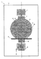
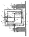
図1及び2を参照しながら、本実施形態に係る三次元回転機構の概略構造について説明する。三次元回転機構1は、矩形の第1枠体3と、第1枠体3を第1回転軸(回転の中心軸となる直線)5の回りで回転させる第1枠体用駆動機構7(モータ7)と、第1枠体3の枠内に配した(すなわち、第1枠体3よりも小型の)矩形の第2枠体9と、第2枠体9を、第1枠体3の回転に従動して、当該第1回転軸5と直交する第2回転軸11の回りで回転させる第1従動機構13と、第2枠体9の枠内に配した被回転体15と、被回転体15を、第2枠体9の回転に従動して、第3回転軸(本実施形態では第1回転軸と一致)の回りで回転させる第2従動機構17と、を含めて構成してある。第1枠体3及び第2枠体9の姿勢は、本実施形態では両者とも起立させてある(第1回転軸が水平)が、これに限る必要はなく、これを横にしたり斜めにしたりすることもできる。両者をモータ7の回転方向は時計方向、反時計方向のいずれでもよい。モータ7の回転方向を定めることにより、第1枠体3の回転方向が定まり、さらに、これに従動する第2枠体9の回転方向が定まる。本実施形態では、図1の右側から見て反時計回りに回転するように構成した。したがって、第1枠体3も、時計回りに回転する。なお、符号2は、装置全体の基礎となるベース部を示す。(Schematic structure of the three-dimensional rotation mechanism)
The schematic structure of the three-dimensional rotation mechanism according to this embodiment will be described with reference to FIGS. The three-dimensional rotation mechanism 1 includes a rectangular first frame body 3 and a first frame
(第1従動機構の構造)
引き続き図1及び2を参照しながら、説明を続ける。第1従動機構13は、第1枠体3の枠内で第1枠体3と同軸一体回転する第1固定軸19と、第1固定軸19の先端に第1固定軸19に対して回転不能に同軸固定した第1固定原車21と、第2枠体9と同軸一体回転するように第2枠体9の枠外に固定した第1回転従車23と、を含めて構成してある。ここで、図1に示す第1固定軸19は、モータ61により回転可能ではあるが、ここでは、モータ61を回転させないことを前提としている。つまり、第1固定軸19には、ブレーキ(図示を省略)を掛けてある。モータ61を省略して第1固定軸19を第1枠体3に対して固定するように構成してもよい。第1回転従車23は、第2枠体9の回転半径よりも大径に構成してある。これにより、平面視したときに第2枠体よりも第1回転従車23が放射方向に径が大きい分だけはみ出ることになる。第1固定原車21と第1回転従車23は、両者ともに摩擦車であり、第1固定原車21の周端面と第1回転従車23(の第2枠体からはみ出した部分)の上面周縁とが互いに垂直に接触するようになっている。ここで、第1枠体3が回転するとこれと一体に第1固定原車21が回転する。第1固定原車21の回転は、これと摩擦接触する第1回転従車23を従動回転させる。第1回転従車23の回転は、それと一体の第2枠体9を回転させる。この回転を自転とすれば、第2枠体9は、自転しながら第1枠体3とともに公転することになる。第1固定原車21と第1回転従車23は、上述したように互いに摩擦接触する摩擦車同士であるが、その代わりに互いに噛み合う歯車同士によって構成することもできる。以上の構成によれば、モータ7が第1枠体3を回転させ、第1枠体3の回転に伴う第1固定原車21の回転が、摩擦伝達によって第1回転従車23及びそれと一体の第2枠体9を従動回転させる。(Structure of the first driven mechanism)
The description will be continued with continued reference to FIGS. The first driven
(第2従動機構の構造)
図1及び2に示すように第2従動機構17は、第2枠体主軸受け機構25と、第2枠体副軸受け機構27と、第2固定軸29と、第2固定原車33と、第2回転従車35と、を含めて構成してある。第2枠体主軸受け機構25及び第2枠体副軸受け機構27は、協働によって、第2枠体9を第1枠体3に対して第2回転軸11の回りで回転自在とするように構成してある。第2固定軸29は、第2回転軸11と同軸であって、第2固定軸29の一端は第2枠体9の枠内に突き出し、他端は第1枠体3に回転不能に固定してある。第2枠体主軸受け機構25は、第1枠体3と第2枠体9のうちいずれか一方に対して回転不能に固定し他方に対して回転自在に固定(本実施形態では第2枠体9に対して固定、第1枠体3に対して回転自在、逆でもよい)した中空軸37と、中空軸37内を通過させた第2固定軸29に対して回転自在とする中空軸内軸受け31と、を含めて構成してある。第2枠体9の枠内にある第2固定軸29の一端には、第2固定原車33を回転不能に同軸固定してある。第2固定軸29は、第2固定原車33の半径と垂直をなす。第2固定軸29は第1枠体3に対して回転しないので、第2固定原車33も第1枠体3に対して回転しない。(Structure of second driven mechanism)
As shown in FIGS. 1 and 2, the second driven
第2回転従車35は、第1回転軸5と同軸であって、第2枠体9に対して第2枠体従車軸受け39を介して回転自在に固定かつ被回転体15に対して回転不能に固定してある。すなわち、被回転体15は、第2回転従車35と一体回転するようになっている。第2固定原車33と第2回転従車35は、両者とも互いに垂直に摩擦接触する摩擦車によって構成してある。両者を、互いに噛み合う歯車同士によって構成してもよいことは、第1従動機構13の場合と異ならない。上記構成において第2枠体9の回転によって第2回転従車35の周端面が第2固定原車33の下面周縁を接触しながら周回し、その際に受ける摩擦伝達によって第2回転従車35が従動回転するようになっている。第2回転従車35が回転すれば、これと一体の被回転体35も回転する。被回転体15には、3軸回転による遠心力が作用するので、2軸回転に比べてこれらの遠心力が重力と同じかそれ以上になり難い。 The
ここで、モータ61に説明を戻す。モータ61は、回転方向と回転速度を変えることのできる可逆可変モータである。先の説明ではモータ61は回転しないことを前提としたが、その前提を解除してこれを回転させるようにすると次のようになる。モータ61の回転方向を、第1固定原車21が第2枠体9と同方向に回転するように定めれば、第1従動機構13とモータ61の協働により第2枠体9を回転させることになる。すなわち、図1の右から見たモータ7を反時計方向に回転させると、第1枠体3とともに第1固定原車21が右方向から見て同じく反時計方向に回転する。第1固定原車21の反時計方向の回転は、第1回転従車23を平面視時計方向に回転させる。ここで、モータ61を、上記と同方向、すなわち、右から見た反時計方向に回転させれば、モータ7の回転方向に対して順方向の回転であるから、両者が協働関係を形成する。他方、モータ61の回転方向を、第1固定原車21が第2枠体9と逆方向(右から見て時計方向)に回転するように定めると、上記逆方向(平面視反時計方向)に第2枠体9を回転させることができる。第2枠体9の(モータ7の回転方向に対する)逆方向回転が許容されるのは、第2枠体主軸受け機構25および第2枠体副軸受け機構27の働きにより第2枠体9が第1枠体3に対して回転可能(第2枠体9の回転が第1枠体3に影響を与えない)であり、かつ、第2回転従車35が第2枠体9に対して回転可能に構成してあるからである。なお、この場合の枠体3は、モータ7により、原則どおり、図1の右から見て反時計方向に回転する Here, the description returns to the
(本実施形態の変形例)
図3を参照しながら、本実施形態の変形例について説明する。先に説明した本実施形態と本実施形態の変形例(以下、「本変形例」という)の違いは、第2従動機構と被回転体のみである。したがって、ここでは、上記部位を中心に説明を行い、両者共通する部位については図1及び2で用いた符号と同じ符号を図3に用いるに止めそれらの説明は可能な範囲で省略する。(Modification of this embodiment)
A modification of the present embodiment will be described with reference to FIG. The difference between this embodiment described above and the modification of this embodiment (hereinafter referred to as “this modification”) is only the second driven mechanism and the rotated body. Therefore, here, the description will be focused on the above-mentioned parts, and the same reference numerals as those used in FIGS. 1 and 2 will be used in FIG. 3 for the parts common to both, and their description will be omitted as far as possible.
本変形例に係る第2従動機構47は、第2枠体主軸受け機構25と、第2枠体副軸受け機構27と、第2固定軸49と、固定補助軸受け51と、第2固定原車53と、第2回転従車55(ここでは2個だが、少なくとも1個あればよい)と、を含めて構成してある。第2枠体主軸受け機構25及び第2枠体副軸受け機構27は、協働して、第2枠体9を第1枠体3に対して回転自在とするように構成してある。この点は、本実施形態と異ならない。第2固定軸49は、第2回転軸11と同軸であって、第2固定軸49の一端は第2枠体9の枠内に一端を突き出し、他端は第1枠体3に回転不能に固定してある。第2枠体主軸受け機構25は、本実施形態におけるそれと同じ構造である。第2固定軸49の一端は、第2固定軸49に対して第2枠体9が回転自在となるように固定補助軸受け51を介して第2枠体9の第2枠体主軸受け機構25と対向する部位に固定してある。第2固定原車53は、第2固定軸49の長さ方向途中(本変形例では第2枠体9のほぼ中央)に回転不能に同軸固定してある。第2回転従車55は、第2回転軸11と平行軸であって、第2枠体9に対して第2枠体従車軸受け57を介して回転自在に固定かつ被回転体59,59に対して回転不能に固定してある。第2固定原車53と第2回転従車55とは、互いに噛み合う歯車同士である。互いに摩擦接触する摩擦車同士によって構成してもよい。ここで、第2枠体9の回転によって第2回転従車55が第2固定原車53の周縁を周回する際に受ける歯車伝達によって第2回転従車55を従動回転させ、これによって被回転体59,59も回転する。被回転体59,59には、3軸回転による遠心力が作用する。被回転体59,59は第2回転原車53の回りを回ることになるので、その分、第2固定軸(第2回転軸)から離れる(第2枠体9の中心領域に存在しない)ことになり、離れた分だけより大きな遠心力を受ける。 The second driven
(三次元回転機構の応用例)
三次元回転機構1は、様々な用途に応用することができる。たとえば、3軸のクリノスタットがその典型例である。さらに、たとえば、これをボールミルに応用して上述した被回転体15をボールを入れたミルポットにすれば、供回り現状が有効に抑えられるので高速回転が可能となり、それにより効率のよい粉砕を期待することができる。コンクリートミキサー車が搭載する混練装置、攪拌装置等にも好適に応用することができる。(Application example of three-dimensional rotation mechanism)
The three-dimensional rotation mechanism 1 can be applied to various uses. For example, a triaxial clinostat is a typical example. Furthermore, for example, if this is applied to a ball mill and the above-mentioned rotated
1・・・三次元回転装置、2・・・ベース部、3・・・第1枠体、5・・・第1回転軸、7・・・第1枠体用駆動機構(モータ)、9・・・第2枠体、11・・・第2回転軸、13・・・第1従動機構、15・・・被回転体、17・・・第2従動機構、19・・・第1固定軸、20・・・第1固定軸受け、21・・・第1固定原車、23・・・第1回転従車、25・・・第2枠体主軸受け機構、27・・・第2枠体副軸受け機構、29・・・第2固定軸、31・・・中空軸内軸受け、33・・・第2固定原車、35・・・第2回転従車、37・・・中空軸、39・・・第2枠体従車軸受け、47・・・第2従動機構、49・・・第2固定軸、53・・・第2固定原車、55・・・第2回転従車、57・・・第2枠体従車軸受け、59・・・被回転体DESCRIPTION OF SYMBOLS 1 ... Three-dimensional rotation apparatus, 2 ... Base part, 3 ... 1st frame, 5 ... 1st rotating shaft, 7 ... 1st frame drive mechanism (motor), 9 ... Second frame, 11 ... Second rotating shaft, 13 ... First driven mechanism, 15 ... Rotated body, 17 ... Second driven mechanism, 19 ... First fixed Axis, 20 ... first fixed bearing, 21 ... first fixed original vehicle, 23 ... first rotating slave, 25 ... second frame main bearing mechanism, 27 ... second frame Body sub-bearing mechanism, 29 ... second fixed shaft, 31 ... bearing in the hollow shaft, 33 ... second fixed original vehicle, 35 ... second rotating slave wheel, 37 ... hollow shaft, 39 ... 2nd frame slave wheel bearing, 47 ... 2nd driven mechanism, 49 ... 2nd fixed shaft, 53 ... 2nd fixed original vehicle, 55 ... 2nd rotation slave wheel, 57... Second frame slave wheel bearing, 59. Rotary body
Claims (10)
当該第1枠体を第1回転軸の回りで回転させる第1枠体用駆動機構と、
当該第1枠体の枠内に配した第2枠体と、
当該第2枠体を、当該第1枠体の回転に従動して、当該第1回転軸と直交する第2回転軸の回りで回転させる第1従動機構と、
当該第2枠体の枠内に配した被回転体と、
当該被回転体を、当該第2枠体の回転に従動して、第3回転軸の回りで回転させる第2従動機構と、
を含めて構成してある
ことを特徴とする三次元回転機構。A first frame,
A first frame driving mechanism for rotating the first frame around the first rotation axis;
A second frame disposed within the frame of the first frame,
A first driven mechanism for rotating the second frame around the second rotation axis perpendicular to the first rotation axis following the rotation of the first frame;
A rotated body disposed within the frame of the second frame;
A second driven mechanism for rotating the rotated body around the third rotation axis following the rotation of the second frame;
A three-dimensional rotation mechanism characterized by comprising.
当該第1回転従車が、前記第2枠体の回転半径よりも大径に構成してあり、
当該第1固定原車と当該第1回転従車とが、噛み合った歯車同士又は摩擦接触し合った摩擦車同士によって構成してあり、
前記第1枠体の回転による当該第1固定原車の回転が、歯車伝達又は摩擦伝達によって当該第1回転従車を従動回転させるように構成してある
ことを特徴とすることを特徴とする請求項1記載の三次元回転機構。The first driven mechanism includes a first fixed shaft that rotates coaxially with the first frame body within the frame of the first frame body and out of the frame of the second frame body, and the first fixed shaft at the tip of the first fixed shaft. Including a first fixed original vehicle that is coaxially fixed so as not to rotate with respect to one fixed shaft, and a first rotating slave vehicle that is fixed outside the second frame body so as to rotate integrally with the second frame body. Configured,
The first rotation slave wheel is configured to have a larger diameter than the rotation radius of the second frame,
The first fixed original vehicle and the first rotating slave vehicle are constituted by meshed gears or friction wheels that are in frictional contact with each other,
The rotation of the first fixed original vehicle due to the rotation of the first frame is configured to rotate the first rotation slave vehicle by gear transmission or friction transmission. The three-dimensional rotation mechanism according to claim 1.
当該第2枠体主軸受け機構が、前記第1枠体と前記第2枠体のうちいずれか一方に対して回転不能に固定し他方に対して回転自在に固定した中空軸と、当該中空軸内を通過させた当該第2固定軸に対して回転自在とする中空軸内軸受けと、を含めて構成してあり、
当該第2枠体副軸受け機構が、当該第2枠体主軸受け機構と協働して前記第2枠体を前記第1枠体に対して回転自在とするように構成してあり、
当該第2固定軸が、前記第2回転軸と同軸であって、当該第2固定軸の一端が前記第2枠体の枠内に突き出し、他端が前記第1枠体に回転不能に固定してあり、
当該第2固定原車が、当該第2固定軸一端に回転不能に同軸固定してあり、
当該第2回転従車が、前記第1回転軸と同軸であって、前記第2枠体に対して第2枠体従車軸受けを介して回転自在に固定かつ前記被回転体に対して回転不能に固定してあり、
当該第2回転従車には、前記被回転体を一体回転するように固定してあり、
当該第2固定原車と当該第2回転従車とが、噛み合った歯車同士又は摩擦接触し合った摩擦車同士によって構成してあり、
前記第2枠体の回転によって当該第2回転従車が当該第2固定原車周縁を周回する際に受ける歯車伝達又は摩擦伝達によって当該第2回転従車を従動回転させるように構成してある
ことを特徴とすることを特徴とする請求項2記載の三次元回転機構。The second driven mechanism includes a second frame main bearing mechanism, a second frame sub-bearing mechanism, a second fixed shaft, a second fixed original vehicle, and a second rotary driven vehicle. And
The second frame main bearing mechanism is fixed to be non-rotatable with respect to one of the first frame and the second frame, and is fixed to be rotatable with respect to the other, and the hollow shaft And a hollow shaft inner bearing that is rotatable with respect to the second fixed shaft that has been passed through,
The second frame sub-bearing mechanism is configured to cooperate with the second frame main bearing mechanism so that the second frame is rotatable with respect to the first frame.
The second fixed shaft is coaxial with the second rotation shaft, one end of the second fixed shaft protrudes into the frame of the second frame, and the other end is fixed to the first frame so as not to rotate. And
The second fixed vehicle is coaxially fixed to one end of the second fixed shaft so as not to rotate;
The second rotating slave wheel is coaxial with the first rotating shaft, and is rotatably fixed to the second frame member via a second frame slave wheel bearing and rotated with respect to the rotated member. Fixed impossible,
In the second rotating slave wheel, the rotated body is fixed so as to rotate integrally,
The second fixed master vehicle and the second rotating slave vehicle are constituted by meshed gears or friction wheels that are in frictional contact with each other,
The second rotating slave is driven to rotate by gear transmission or friction transmission received when the second rotating slave rotates around the periphery of the second fixed master vehicle by the rotation of the second frame. The three-dimensional rotation mechanism according to claim 2, wherein
当該第2枠体主軸受け機構が、前記第1枠体と前記第2枠体のうちいずれか一方に対して回転不能に固定し他方に対して回転自在に固定した中空軸と、当該中空軸内を通過させた当該第2固定軸に対して回転自在とする中空軸内軸受けと、を含めて構成してあり、
当該第2枠体副軸受け機構が、当該第2枠体主軸受け機構と協働して前記第2枠体を前記第1枠体に対して回転自在とするように構成してあり、
当該第2固定軸が、前記第2回転軸と同軸であって、当該第2固定軸の一端が前記第2枠体の枠内に突き出し、他端が前記第1枠体に回転不能に固定してあり、
当該第2固定軸の一端が、当該第2固定軸に対して前記第2枠体が回転自在となるように固定補助軸受けを介して前記第2枠体に固定してあり、
当該第2固定原車が、当該第2固定軸途中に回転不能に同軸固定してあり、
当該第2回転従車が、前記第2回転軸と平行軸であって、前記第2枠体に対して第2枠体従車軸受けを介して回転自在に固定かつ前記被回転体に対して回転不能に固定してあり、
当該第2固定原車と当該第2回転従車とが、噛み合った歯車同士又は摩擦接触し合った摩擦車同士によって構成してあり、
前記第2枠体の回転によって当該第2回転従車が当該第2固定原車周縁を周回する際に受ける歯車伝達又は摩擦伝達によって当該第2回転従車を従動回転させるように構成してある
ことを特徴とすることを特徴とする請求項2記載の三次元回転機構。The second driven mechanism includes at least a second frame main bearing mechanism, a second frame sub bearing mechanism, a second fixed shaft, a fixed auxiliary bearing, a second fixed master vehicle, and a second rotating slave vehicle. And is composed of
The second frame main bearing mechanism is fixed to be non-rotatable with respect to one of the first frame and the second frame, and is fixed to be rotatable with respect to the other, and the hollow shaft And a hollow shaft inner bearing that is rotatable with respect to the second fixed shaft that has been passed through,
The second frame sub-bearing mechanism is configured to cooperate with the second frame main bearing mechanism so that the second frame is rotatable with respect to the first frame.
The second fixed shaft is coaxial with the second rotation shaft, one end of the second fixed shaft protrudes into the frame of the second frame, and the other end is fixed to the first frame so as not to rotate. And
One end of the second fixed shaft is fixed to the second frame via a fixed auxiliary bearing so that the second frame is rotatable with respect to the second fixed shaft,
The second fixed vehicle is coaxially fixed so as not to rotate in the middle of the second fixed shaft,
The second rotating slave wheel is a shaft parallel to the second rotating shaft, and is fixed to the second frame body rotatably via a second frame slave wheel bearing and to the rotated body. Fixed non-rotatable,
The second fixed master vehicle and the second rotating slave vehicle are constituted by meshed gears or friction wheels that are in frictional contact with each other,
The second rotating slave is driven to rotate by gear transmission or friction transmission received when the second rotating slave rotates around the periphery of the second fixed master vehicle by the rotation of the second frame. The three-dimensional rotation mechanism according to claim 2, wherein
当該第1枠体を第1回転軸の回りで回転させる第1枠体用駆動機構と、
当該第1枠体の枠内に配した第2枠体と、
当該第2枠体を、当該第1回転軸と直交する第2回転軸の回りで回転させる第2枠体用駆動機構と、
当該第2枠体の枠内に配した被回転体と、
当該被回転体を、当該第2枠体の回転に従動して、第3回転軸の回りで回転させる被回転体従動機構と、
を含めて構成してある
ことを特徴とする三次元回転機構。A first frame,
A first frame driving mechanism for rotating the first frame around the first rotation axis;
A second frame disposed within the frame of the first frame,
A second frame body drive mechanism for rotating the second frame body around a second rotation axis orthogonal to the first rotation axis;
A rotated body disposed within the frame of the second frame;
A rotated body driven mechanism that rotates the rotated body around the third rotation axis following the rotation of the second frame;
A three-dimensional rotation mechanism characterized by comprising.
当該第1回転従車が、前記第2枠体の回転半径よりも大径に構成してあり、
当該第1固定原車と当該第1回転従車とが、噛み合った歯車同士又は摩擦接触し合った摩擦車同士によって構成してあり、
当該可変可逆モータの回転による当該第1固定原車の回転が、歯車伝達又は摩擦伝達によって当該第1回転従車を従動回転させるように構成してある
ことを特徴とすることを特徴とする請求項2記載の三次元回転機構。A first rotating shaft fixed to the first frame via a first rotating shaft bearing so that the second frame driving mechanism is coaxially rotatable with the first frame; and the first rotating shaft A variable reversible motor that rotates the first rotation shaft, a first fixed original vehicle that is coaxially fixed to the tip of the first rotation shaft so as not to rotate with respect to the first rotation shaft, and the second frame body so as to rotate integrally therewith. A first rotating slave fixed outside the second frame body frame,
The first rotation slave wheel is configured to have a larger diameter than the rotation radius of the second frame,
The first fixed original vehicle and the first rotating slave vehicle are constituted by meshed gears or friction wheels that are in frictional contact with each other,
The rotation of the first fixed original vehicle by the rotation of the variable reversible motor is configured to rotate the first rotation slave vehicle by gear transmission or friction transmission. Item 3. A three-dimensional rotation mechanism according to item 2.
当該第2枠体主軸受け機構が、前記第1枠体と前記第2枠体のうちいずれか一方に対して回転不能に固定し他方に対して回転自在に固定した中空軸と、当該中空軸内を通過させた当該第1枠体固定軸に対して回転自在とする中空軸内軸受けと、を含めて構成してあり、
当該第2枠体副軸受け機構が、当該第2枠体主軸受け機構と協働して前記第2枠体を前記第1枠体に対して回転自在とするように構成してあり、
当該第1枠体固定軸が、前記第2回転軸と同軸であって、当該第2固定軸の一端が前記第2枠体の枠内に突き出し、他端が前記第1枠体に回転不能に固定してあり、
当該第1枠体固定原車が、当該第1枠体固定軸一端に回転不能に同軸固定してあり、
当該第1枠体回転従車が、前記第1回転軸と同軸であって、前記第2枠体に対して第2枠体従車軸受けを介して回転自在に固定かつ前記被回転体に対して回転不能に固定してあり、
当該第1枠体固定原車と当該第1枠体回転従車とが、噛み合った歯車同士又は摩擦接触し合った摩擦車同士によって構成してあり、
前記第2枠体の回転によって当該第1枠体回転従車が当該第1枠体固定原車周縁を周回する際に受ける歯車伝達又は摩擦伝達によって当該第1枠体回転従車を従動回転させるように構成してある
ことを特徴とすることを特徴とする請求項1又は2記載の三次元回転機構。The rotating body driven mechanism includes a second frame main bearing mechanism, a second frame sub bearing mechanism, a first frame fixing shaft, a first frame fixing original vehicle, and a first frame rotating driven vehicle. , Including
The second frame main bearing mechanism is fixed to be non-rotatable with respect to one of the first frame and the second frame, and is fixed to be rotatable with respect to the other, and the hollow shaft A hollow shaft inner bearing that is rotatable with respect to the first frame fixed shaft that has been passed through,
The second frame sub-bearing mechanism is configured to cooperate with the second frame main bearing mechanism so that the second frame is rotatable with respect to the first frame.
The first frame fixing shaft is coaxial with the second rotation shaft, one end of the second fixing shaft protrudes into the frame of the second frame, and the other end cannot rotate with respect to the first frame. It is fixed to
The first frame fixed original vehicle is coaxially fixed to one end of the first frame fixed shaft so as not to rotate,
The first frame rotating slave is coaxial with the first rotating shaft, and is rotatably fixed to the second frame via a second frame supporting vehicle bearing, and is fixed to the rotated body. And fixed so that it cannot rotate.
The first frame fixed master vehicle and the first frame rotating slave vehicle are configured by meshed gears or friction wheels that are in frictional contact with each other,
The first frame rotating slave is driven to rotate by gear transmission or friction transmission received when the first frame rotating slave rotates around the periphery of the first frame fixed master vehicle by the rotation of the second frame. The three-dimensional rotation mechanism according to claim 1, wherein the three-dimensional rotation mechanism is configured as described above.
当該第1中空軸内軸受け構造が、前記第1枠体と前記第2枠体のうちいずれか一方に対して回転不能に固定し他方に対して回転自在に固定した中空軸と、当該中空軸内を通過させた当該第2固定軸に対して回転自在とする中空軸内軸受けと、を含めて構成してあり、
当該第2枠体副軸受け機構が、当該第2枠体主軸受け機構と協働して前記第2枠体を前記第1枠体に対して回転自在とするように構成してあり、
当該第2固定軸が、前記第2回転軸と同軸であって、当該第2固定軸の一端が前記第2枠体の枠内に突き出し、他端が前記第1枠体に回転不能に固定してあり、
当該第2固定軸の一端が、当該第2固定軸に対して前記第2枠体が回転自在となるように固定補助軸受けを介して前記第2枠体に固定してあり、
当該第2固定原車が、当該第2固定軸途中に回転不能に同軸固定してあり、
当該第2回転従車が、前記第2回転軸と平行軸であって、前記第2枠体に対して第2枠体従車軸受けを介して回転自在に固定かつ前記被回転体に対して回転不能に固定してあり、
当該第2固定原車と当該第2回転従車とが、噛み合った歯車同士又は摩擦接触し合った摩擦車同士によって構成してあり、
前記第2枠体の回転によって当該第2回転従車が当該第2固定原車周縁を周回する際に受ける歯車伝達又は摩擦伝達によって当該第2回転従車を従動回転させるように構成してある
ことを特徴とすることを特徴とする請求項1又は2記載の三次元回転機構。The second driven mechanism includes at least a second frame main bearing mechanism, a second frame sub bearing mechanism, a second fixed shaft, a fixed auxiliary bearing, a second fixed master vehicle, and a second rotating slave vehicle. And is composed of
The hollow shaft in which the first hollow shaft inner bearing structure is fixed so as not to rotate with respect to one of the first frame body and the second frame body, and rotatably fixed with respect to the other, and the hollow shaft And a hollow shaft inner bearing that is rotatable with respect to the second fixed shaft that has been passed through,
The second frame sub-bearing mechanism is configured to cooperate with the second frame main bearing mechanism so that the second frame is rotatable with respect to the first frame.
The second fixed shaft is coaxial with the second rotation shaft, one end of the second fixed shaft protrudes into the frame of the second frame, and the other end is fixed to the first frame so as not to rotate. And
One end of the second fixed shaft is fixed to the second frame via a fixed auxiliary bearing so that the second frame is rotatable with respect to the second fixed shaft,
The second fixed vehicle is coaxially fixed so as not to rotate in the middle of the second fixed shaft,
The second rotating slave wheel is a shaft parallel to the second rotating shaft, and is fixed to the second frame body rotatably via a second frame slave wheel bearing and to the rotated body. Fixed non-rotatable,
The second fixed master vehicle and the second rotating slave vehicle are constituted by meshed gears or friction wheels that are in frictional contact with each other,
The second rotating slave is driven to rotate by gear transmission or friction transmission received when the second rotating slave rotates around the periphery of the second fixed master vehicle by the rotation of the second frame. The three-dimensional rotation mechanism according to claim 1 or 2, characterized by the above.
前記三次元回転機構の被回転体が、内部にボールを有するミルポットを含めて構成してある
ことを特徴とするボールミル。A three-dimensional rotation mechanism according to any one of claims 1 to 8,
The ball mill characterized in that the rotated body of the three-dimensional rotation mechanism includes a mill pot having a ball inside.
前記三次元回転機構の被回転体が、内部に被混練体を収容可能な収容容器を含めて構成してある
ことを特徴とする混練装置。A three-dimensional rotation mechanism according to any one of claims 1 to 8,
The kneading apparatus characterized in that the rotating body of the three-dimensional rotation mechanism includes a container that can store the kneading body therein.
Priority Applications (2)
| Application Number | Priority Date | Filing Date | Title |
|---|---|---|---|
| JP2009169511A JP2012176331A (en) | 2009-06-27 | 2009-06-27 | Three-dimensional rotating mechanism, and ball mill and kneading apparatus with the same |
| PCT/JP2010/058290 WO2010150600A1 (en) | 2009-06-27 | 2010-05-17 | Three-dimensional rotation mechanism and ball mill with same |
Applications Claiming Priority (1)
| Application Number | Priority Date | Filing Date | Title |
|---|---|---|---|
| JP2009169511A JP2012176331A (en) | 2009-06-27 | 2009-06-27 | Three-dimensional rotating mechanism, and ball mill and kneading apparatus with the same |
Publications (1)
| Publication Number | Publication Date |
|---|---|
| JP2012176331A true JP2012176331A (en) | 2012-09-13 |
Family
ID=43386378
Family Applications (1)
| Application Number | Title | Priority Date | Filing Date |
|---|---|---|---|
| JP2009169511A Pending JP2012176331A (en) | 2009-06-27 | 2009-06-27 | Three-dimensional rotating mechanism, and ball mill and kneading apparatus with the same |
Country Status (2)
| Country | Link |
|---|---|
| JP (1) | JP2012176331A (en) |
| WO (1) | WO2010150600A1 (en) |
Cited By (12)
| Publication number | Priority date | Publication date | Assignee | Title |
|---|---|---|---|---|
| US20140117131A1 (en) * | 2012-10-31 | 2014-05-01 | Denso Corporation | Centrifugal ball mill |
| JP2014522375A (en) * | 2011-03-03 | 2014-09-04 | ウィシス テクノロジー ファウンデーション,インコーポレイティド | Thermodynamic solutions of metal oxides, metal chalcogenides, mixed metal oxides, and chalcogenides |
| JP2014237111A (en) * | 2013-06-10 | 2014-12-18 | Omc株式会社 | Mixing device and mixing method |
| CN105126968A (en) * | 2015-08-21 | 2015-12-09 | 西北矿冶研究院 | Crushing and grinding device for ore sampling and using method thereof |
| JP2015229138A (en) * | 2014-06-05 | 2015-12-21 | 株式会社ナガオシステム | Crystallizer and crystallization method |
| JP2017159262A (en) * | 2016-03-10 | 2017-09-14 | 国立大学法人大阪大学 | Manufacturing method and manufacturing device of emulsion |
| WO2017187550A1 (en) * | 2016-04-27 | 2017-11-02 | 株式会社ナガオシステム | Mixing method and rotation device |
| JP2020016284A (en) * | 2018-07-25 | 2020-01-30 | 株式会社亀山鉄工所 | Rotating device |
| WO2020045690A1 (en) * | 2018-08-27 | 2020-03-05 | 김태헌 | Mold rotating device |
| JP6777299B1 (en) * | 2020-01-29 | 2020-10-28 | 株式会社ナガオシステム | Grinding method and mixing method |
| WO2022075465A1 (en) * | 2020-10-09 | 2022-04-14 | 三菱マテリアル株式会社 | Container, rotating device, and fine particle production method |
| JP2022063167A (en) * | 2020-10-09 | 2022-04-21 | 株式会社ナガオシステム | Container, rotation device, and fine particle production method |
Families Citing this family (14)
| Publication number | Priority date | Publication date | Assignee | Title |
|---|---|---|---|---|
| US20110013479A1 (en) * | 2009-07-15 | 2011-01-20 | Bodhisattwa Chaudhuri | Multi-Dimensional Rotary Mixer |
| CN102160987B (en) * | 2011-04-26 | 2012-05-23 | 四川蓝星机械有限公司 | Leaching ball |
| GB2509507B (en) * | 2013-01-04 | 2018-01-24 | Kenwood Ltd | Three-dimensional stirring/mixing utensils |
| JP6249361B2 (en) * | 2013-06-24 | 2017-12-20 | 株式会社スペース・バイオ・ラボラトリーズ | Gravity fluctuation device for cell culture |
| CN104759225A (en) * | 2015-04-23 | 2015-07-08 | 方珠康 | All-around movement high-efficiency mixer |
| JP6293173B2 (en) * | 2016-01-22 | 2018-03-14 | 株式会社メルビル | Demagnetizing rotating device |
| ES2967069T3 (en) * | 2018-04-18 | 2024-04-25 | Ingesea Automation Sl | Apparatus and method for generating microgravity |
| CN109174268B (en) * | 2018-08-08 | 2020-07-07 | 南通立方新材料科技有限公司 | Grinding stirring processing equipment for paint production |
| JP2020075201A (en) * | 2018-11-05 | 2020-05-21 | 株式会社亀山鉄工所 | Thin piece manufacturing method |
| CN109794328A (en) * | 2019-03-24 | 2019-05-24 | 山东科技大学 | A small ball mill specially used for crushing a small amount of samples |
| CN112705086A (en) * | 2020-12-30 | 2021-04-27 | 浙江大学台州研究院 | Automatic mixing machine |
| CN113457519A (en) * | 2021-07-21 | 2021-10-01 | 吉林大学 | Three-dimensional powder mixer |
| CN116899695B (en) * | 2023-07-13 | 2024-03-19 | 永州明睿陶瓷科技有限公司 | Mixed ball milling device of colored zirconia ceramic |
| CN117696901A (en) * | 2023-10-30 | 2024-03-15 | 沈阳工业大学 | Pretreatment device and method for carbon fiber metal matrix composite |
Family Cites Families (4)
| Publication number | Priority date | Publication date | Assignee | Title |
|---|---|---|---|---|
| US3287981A (en) * | 1964-05-20 | 1966-11-29 | Wolfe John Sohn | Generation of rotations about a fixed point with symmetric and near symmetric distribution of tangential velocity components and rotary components |
| GB2107912A (en) * | 1981-06-13 | 1983-05-05 | Richard Furneaux Kinnersly | Rotational display or amusement device |
| JPH08108086A (en) * | 1994-10-11 | 1996-04-30 | Noriya Ikeda | Tea leaf pulverizing machine |
| JP4974283B2 (en) * | 2007-04-26 | 2012-07-11 | 株式会社ナガオシステム | Clinostat |
-
2009
- 2009-06-27 JP JP2009169511A patent/JP2012176331A/en active Pending
-
2010
- 2010-05-17 WO PCT/JP2010/058290 patent/WO2010150600A1/en not_active Ceased
Cited By (21)
| Publication number | Priority date | Publication date | Assignee | Title |
|---|---|---|---|---|
| JP2014522375A (en) * | 2011-03-03 | 2014-09-04 | ウィシス テクノロジー ファウンデーション,インコーポレイティド | Thermodynamic solutions of metal oxides, metal chalcogenides, mixed metal oxides, and chalcogenides |
| US10112156B2 (en) | 2011-03-03 | 2018-10-30 | Wisys Technology Foundation, Inc. | Thermodynamic solutions of metal chalcogenides and mixed metal oxides and chalcogenides |
| US20140117131A1 (en) * | 2012-10-31 | 2014-05-01 | Denso Corporation | Centrifugal ball mill |
| JP2014237111A (en) * | 2013-06-10 | 2014-12-18 | Omc株式会社 | Mixing device and mixing method |
| JP2015229138A (en) * | 2014-06-05 | 2015-12-21 | 株式会社ナガオシステム | Crystallizer and crystallization method |
| US9365950B2 (en) | 2014-06-05 | 2016-06-14 | Nagao System Inc. | Crystallizer and method of crystallization |
| CN105126968A (en) * | 2015-08-21 | 2015-12-09 | 西北矿冶研究院 | Crushing and grinding device for ore sampling and using method thereof |
| JP2017159262A (en) * | 2016-03-10 | 2017-09-14 | 国立大学法人大阪大学 | Manufacturing method and manufacturing device of emulsion |
| WO2017187550A1 (en) * | 2016-04-27 | 2017-11-02 | 株式会社ナガオシステム | Mixing method and rotation device |
| JP2020016284A (en) * | 2018-07-25 | 2020-01-30 | 株式会社亀山鉄工所 | Rotating device |
| WO2020045690A1 (en) * | 2018-08-27 | 2020-03-05 | 김태헌 | Mold rotating device |
| JP6777299B1 (en) * | 2020-01-29 | 2020-10-28 | 株式会社ナガオシステム | Grinding method and mixing method |
| WO2021152725A1 (en) * | 2020-01-29 | 2021-08-05 | 株式会社ナガオシステム | Pulverizing method and mixing method |
| JP2021115567A (en) * | 2020-01-29 | 2021-08-10 | 株式会社ナガオシステム | Slewing gear, pulverization method and blending method |
| JP2021115568A (en) * | 2020-01-29 | 2021-08-10 | 株式会社ナガオシステム | Pulverization method and blending method |
| DE112020006620T5 (en) | 2020-01-29 | 2023-03-09 | Nagao System Inc. | pulverization method and mixing method |
| JP7421700B2 (en) | 2020-01-29 | 2024-01-25 | 株式会社ナガオシステム | Rotating equipment, grinding methods and mixing methods |
| JP7428863B2 (en) | 2020-01-29 | 2024-02-07 | 株式会社ナガオシステム | Grinding and mixing methods |
| WO2022075465A1 (en) * | 2020-10-09 | 2022-04-14 | 三菱マテリアル株式会社 | Container, rotating device, and fine particle production method |
| JP2022063167A (en) * | 2020-10-09 | 2022-04-21 | 株式会社ナガオシステム | Container, rotation device, and fine particle production method |
| JP7678253B2 (en) | 2020-10-09 | 2025-05-16 | 三菱マテリアル株式会社 | Container, rotating device and method for producing fine particles |
Also Published As
| Publication number | Publication date |
|---|---|
| WO2010150600A1 (en) | 2010-12-29 |
Similar Documents
| Publication | Publication Date | Title |
|---|---|---|
| JP2012176331A (en) | Three-dimensional rotating mechanism, and ball mill and kneading apparatus with the same | |
| JP2014061744A (en) | Steering device and vehicle | |
| JP5128314B2 (en) | Ball reducer and rotary table device using the same | |
| CN104225927B (en) | A kind of two-sided toy car | |
| US20020104704A1 (en) | Transmission structrue of gearbox of electrically actuated car | |
| CN105270169A (en) | Automobile capable of steering in situ and running in transverse direction | |
| JP2006254629A5 (en) | ||
| CN105460128B (en) | Synchronous movement scooter | |
| JP5718285B2 (en) | Centrifuge, drive mechanism, and drive method | |
| JP3683173B2 (en) | Planetary ball mill | |
| CN101537503A (en) | Multifunctional combined type power turret of computer numerical control lathe | |
| CN201135780Y (en) | Movement mechanism of multifunctional spheroid toy | |
| CN115958946A (en) | Drive axle for vehicle and vehicle having same | |
| CN204121750U (en) | A kind of two-sided toy car | |
| CN206876943U (en) | An optical lens that can realize the viewing range of 180° on the X axis and 360° on the Z axis | |
| CN206664683U (en) | A kind of universal chassis of diagonal wheel drive | |
| CN202209039U (en) | Sand mill | |
| CN102389735A (en) | Mixing machine | |
| CN108301664A (en) | A kind of small-sized differential gear train formula stereo garage | |
| JP2008155286A (en) | Barrel polishing method and apparatus | |
| CN214274427U (en) | Multi-stage variable speed driving device | |
| CN201941982U (en) | Spherical rover | |
| JP5513150B2 (en) | Barrel polishing machine | |
| JP5240327B2 (en) | car | |
| CN101110537B (en) | Transmission system with unidirectional gear and rim motor with the transmission system |