JP2012177663A - Pre-freezer - Google Patents
Pre-freezer Download PDFInfo
- Publication number
- JP2012177663A JP2012177663A JP2011041909A JP2011041909A JP2012177663A JP 2012177663 A JP2012177663 A JP 2012177663A JP 2011041909 A JP2011041909 A JP 2011041909A JP 2011041909 A JP2011041909 A JP 2011041909A JP 2012177663 A JP2012177663 A JP 2012177663A
- Authority
- JP
- Japan
- Prior art keywords
- freezer
- preliminary
- induction shaft
- heat induction
- container
- Prior art date
- Legal status (The legal status is an assumption and is not a legal conclusion. Google has not performed a legal analysis and makes no representation as to the accuracy of the status listed.)
- Granted
Links
Images
Landscapes
- Sampling And Sample Adjustment (AREA)
- Packages (AREA)
Abstract
【課題】市販の各種低温液化ガス容器を使用して簡単かつ確実に被凍結物の予備凍結を行うことができる予備凍結器を提供する。
【解決手段】予備凍結器16は、低温液化ガス容器の口栓部の内部に挿入される有底円筒状の凍結器本体17と、凍結器本体の内部に形成された予備凍結室18と、凍結器本体の底部を貫通して低温液化ガス容器の内部と予備凍結室の内部とを熱的に結合する熱誘導軸19と、被凍結物を封入した試料容器24を予備凍結室の内部に保持するとともに、熱誘導軸に熱的に結合した試料容器保持部材20と、予備凍結室の上部開口に装着される蓋部材21と、凍結器本体を口栓部内に保持するための保持部(鍔部22)とを備えている。
【選択図】図1An object of the present invention is to provide a pre-freezer capable of easily and reliably pre-freezing an object to be frozen using various commercially available low-temperature liquefied gas containers.
A preliminary freezer 16 includes a bottomed cylindrical freezer body 17 inserted into a stopper portion of a cryogenic liquefied gas container, a preliminary freezing chamber 18 formed inside the freezer body, A heat induction shaft 19 that thermally penetrates the bottom of the freezer body and thermally couples the inside of the cryogenic liquefied gas container and the inside of the preliminary freezing chamber, and the sample container 24 enclosing the object to be frozen inside the preliminary freezing chamber. A sample container holding member 20 that is held and thermally coupled to the heat induction shaft, a lid member 21 that is attached to the upper opening of the preliminary freezing chamber, and a holding portion for holding the freezer body in the plug portion ( And a collar portion 22).
[Selection] Figure 1
Description
本発明は、予備凍結器に関し、詳しくは、低温液化ガス容器を利用してバイオメディカル、医療、製薬等の基礎研究等に用いられる生体試料やサンプルを緩慢凍結法により予備凍結するための予備凍結器に関する。 The present invention relates to a pre-freezer, and in particular, pre-freezing for pre-freezing a biological sample or sample used for basic research such as biomedical, medical, pharmaceutical, etc. using a low temperature liquefied gas container by a slow freezing method. Related to the vessel.
一般的に、生体試料の凍結保存を行う際には、緩慢凍結法によって生体試料をある温度までゆっくりと予備凍結した後、凍結保存容器内に収容した極低温の液体窒素中に浸漬して凍結保存するようにしている。従来、緩慢凍結法による予備凍結は、生体試料を凍結培地と共にキャップ付きのマイクロチューブやバイアル,アンプル,バッグ等の試料容器に封入し、プログラムフリーザーによって冷却制御しながら−1℃/min程度の速度で温度を下げていって予備凍結したり、生体試料を凍結培地と共に断熱ケースに収容して−80℃程度の恒温保冷庫に所定時間保持して予備凍結したりしている。また、予備凍結にプログラムフリーザーや恒温保冷庫等の機器を用いない方法として、生体試料を収納した凍結容器の蓋を通過可能なフリーザモジュールを配置し、温度制御機構で冷却用ファンの作動を制御しながら生体試料を予備凍結する方法が知られている(例えば、特許文献1参照。)。 In general, when cryopreserving a biological sample, the biological sample is slowly pre-frozen to a certain temperature by a slow freezing method, and then immersed in cryogenic liquid nitrogen contained in a cryopreservation container and frozen. I try to save it. Conventionally, pre-freezing by the slow freezing method is a method in which a biological sample is enclosed in a sample container such as a microtube with a cap, a vial, an ampoule, or a bag together with a freezing medium, and is controlled at a rate of about −1 ° C./min while being controlled by a program freezer. The temperature is lowered and pre-frozen, or the biological sample is housed in a heat insulating case together with a freezing medium, and kept in a constant temperature refrigerator at about −80 ° C. for a predetermined time to be pre-frozen. In addition, as a method that does not use equipment such as a program freezer or a constant temperature refrigerator for pre-freezing, a freezer module that can pass through the lid of a cryocontainer containing biological samples is placed, and the operation of the cooling fan is controlled by the temperature control mechanism A method of pre-freezing a biological sample is known (for example, see Patent Document 1).
一方、前記試料を長期間凍結状態で保存するための凍結保存容器としては、外槽と内槽との間に断熱層を形成した断熱容器が用いられており、前記内槽の上部には、内槽より小径のネック部が上端を開口して連設され、該ネック部の上端開口部に、凍結保存試料を断熱容器内に吊り下げ状態で保持する吊り部材の上部を掛け止めておくための係止部材を設け、さらに、係止部材を含む断熱容器の上方をキャップにて覆うようにしたものが知られている(例えば、特許文献2参照。)。 On the other hand, as a cryopreservation container for storing the sample in a frozen state for a long period of time, a heat insulating container in which a heat insulating layer is formed between an outer tank and an inner tank is used, and in the upper part of the inner tank, A neck part with a smaller diameter than the inner tank is connected to the upper end of the neck part, and the upper part of the suspension part for holding the cryopreserved sample in a suspended state in the heat insulating container is suspended from the upper end opening part of the neck part. There is known a structure in which a locking member is provided and a heat insulating container including the locking member is covered with a cap (see, for example, Patent Document 2).
しかし、上述のプログラムフリーザーや恒温保冷庫を用いるものでは、停電が発生したり、液体窒素の液切れが発生したりすると、生体試料の凍結不良が生じるおそれがある。また、プログラムフリーザーによる予備凍結では、生体試料を封入したマイクロチューブに直接液体窒素を噴霧するため、液体窒素や液体窒素配管に雑菌の混入があると、マイクロチューブのキャップの隙間から雑菌が侵入し、生体試料に雑菌が混入するおそれがあった。 However, in the case of using the above-described program freezer or constant temperature cold storage, if a power failure occurs or liquid nitrogen runs out, there is a possibility that the biological sample may be frozen poorly. In addition, liquid nitrogen is sprayed directly onto the microtube containing the biological sample in the preliminary freezing using the program freezer. Therefore, if there is any contamination in the liquid nitrogen or liquid nitrogen piping, the germ will enter through the gap in the cap of the microtube. There was a risk of contamination of the biological sample.
さらに、特許文献1の方法では、生体試料に雑菌が混入するおそれはないものの、フリーザモジュールや貯蔵部,温度制御機構の構造が複雑で、装置が大型化し、コストも嵩んでいた。また、特許文献2の凍結保存容器は、停電や液体窒素の液切れの発生による凍結不良のおそれがなく、さらに、雑菌の混入を防止することができるが、凍結保存を目的としたものであるから、この凍結保存容器を用いて予備凍結を行うことはできなかった。 Furthermore, in the method of Patent Document 1, although there is no possibility that various bacteria are mixed in the biological sample, the structure of the freezer module, the storage unit, and the temperature control mechanism is complicated, and the apparatus is increased in size and cost. In addition, the cryopreservation container of Patent Document 2 has no fear of freezing failure due to the occurrence of a power failure or the occurrence of liquid nitrogen breakage, and can prevent contamination by germs, but is intended for cryopreservation. Therefore, preliminary freezing could not be performed using this cryopreservation container.
そこで本発明は、被凍結物の緩慢凍結法による被凍結物の予備凍結を、市販の各種低温液化ガス容器を使用して簡単かつ確実に行うことができる予備凍結器を提供することを目的としている。 Therefore, the present invention has an object to provide a pre-freezer capable of easily and surely pre-freezing the object to be frozen by the slow freezing method of the object to be frozen using various commercially available low-temperature liquefied gas containers. Yes.
上記目的を達成するため、本発明の予備凍結器は、低温液化ガスを収容する低温液化ガス容器に設けられた口栓部に着脱可能に装着して緩慢凍結法による予備凍結を行う予備凍結器であって、前記口栓部の内部に挿入される有底円筒状の断熱材からなり、内部に予備凍結室を有する凍結器本体と、該凍結器本体の底部を貫通して前記低温液化ガス容器の内部と前記予備凍結室の内部とを熱的に結合する熱誘導軸と、被凍結物を封入した試料容器を予備凍結室の内部に保持するとともに、前記熱誘導軸に熱的に結合した試料容器保持部材と、前記予備凍結室の上部開口に装着される蓋部材と、前記凍結器本体を前記口栓部内に保持するための保持部とを備えていることを特徴としている。 In order to achieve the above object, the pre-freezer of the present invention is a pre-freezer that pre-freezes by a slow freezing method by being detachably attached to a cap portion provided in a low-temperature liquefied gas container that contains a low-temperature liquefied gas. A freezer main body comprising a bottomed cylindrical heat insulating material inserted into the plug portion, and having a preliminary freezing chamber therein; and the cryogenic liquefied gas passing through the bottom of the freezer body A heat induction shaft that thermally couples the inside of the container and the inside of the preliminary freezing chamber, and a sample container that encloses an object to be frozen is held inside the preliminary freezing chamber and is thermally coupled to the heat induction shaft. The sample container holding member, a lid member attached to the upper opening of the preliminary freezing chamber, and a holding part for holding the freezer main body in the plug part are provided.
さらに、本発明の予備凍結器は、前記熱誘導軸が、前記予備凍結室内で前記試料容器保持部材を支持する支持部材を備えるとともに、試料容器保持部材の支持位置が熱誘導軸の軸線方向に調節可能に形成されていること、前記熱誘導軸の前記低温液化ガス容器の内部に挿入される先端部分の外面に伝熱フィンが突設されていること、前記熱誘導軸が、該熱誘導軸の軸線方向に複数の軸部材を連結して形成されていること、そして、前記低温液化ガス容器が液体窒素式の凍結保存容器であることを特徴としている。 Furthermore, in the preliminary freezer of the present invention, the heat induction shaft includes a support member that supports the sample container holding member in the preliminary freezing chamber, and the support position of the sample container holding member is in the axial direction of the heat induction shaft. It is formed to be adjustable, heat transfer fins project from the outer surface of the tip portion inserted into the low-temperature liquefied gas container of the heat induction shaft, and the heat induction shaft A plurality of shaft members are connected in the axial direction of the shaft, and the cryogenic liquefied gas container is a liquid nitrogen type cryopreservation container.
本発明の予備凍結器によれば、市販の各種低温液化ガス容器の口栓部に対応した形状の凍結器本体を使用することにより、各種低温液化ガス容器を利用して生体試料などの各種被凍結物を緩慢に凍結させることができる。また、停電に影響されることなく、液体窒素の液切れも発生しにくく、雑菌が侵入するおそれもない。特に、簡単な構造であるから、製造コストも低廉であり、取り扱いも容易であることから、緩慢凍結法による予備凍結に要するコストの削減を図ることができる。 According to the preliminary freezer of the present invention, by using a freezer main body having a shape corresponding to the plug portion of various commercially available low-temperature liquefied gas containers, various kinds of samples such as biological samples can be obtained using various low-temperature liquefied gas containers. The frozen material can be frozen slowly. In addition, liquid nitrogen does not easily run out of power without being affected by a power failure, and there is no risk of invasion of germs. In particular, since the structure is simple, the manufacturing cost is low, and the handling is easy. Therefore, the cost required for the preliminary freezing by the slow freezing method can be reduced.
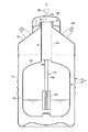
まず、図2に示すように、本発明の予備凍結器で被凍結物を緩慢凍結法により予備凍結する際に使用する低温液化ガス容器としての液体窒素式の凍結保存容器11は、外槽12と内槽13との間に断熱層を形成した断熱容器14からなるものであって、内槽13は、円筒状の容器本体13aと、該容器本体13aの上部に上方が縮径した円錐部13bを介して連設されたネック部(口栓部)13cとが一体的に形成されている。外槽12は、断熱層を介して前記容器本体13aを収容する円筒部12aと、前記口栓部13cを収容する上方が縮径した縮径部12bとが一体的に形成され、該縮径部12bの上端部と前記口栓部13cの上端部とが溶着されて外槽12と内槽13とが一体的に形成されている。
First, as shown in FIG. 2, a liquid
また、口栓部13cの上端開口部には、この凍結保存容器11の本来の使用目的である試料の長期凍結保存を行う際に、凍結保存試料を内槽13内に吊り下げ状態で保持する吊り部材(図示せず)の上部を掛け止めておくためのリング状の係止部材15が設けられている。さらに、係止部材15の上には、口栓部13cの上部を覆う外蓋14aが取り付けられ、上面外周側には、凍結保存容器11を持ち運ぶ際に使用するハンドル14bが設けられている。
In addition, the cryopreserved sample is held in a suspended state in the
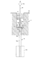
このように形成された凍結保存容器11を使用して緩慢凍結法による試料の予備凍結を行うための予備凍結器16は、図1に示すように、前記口栓部13cの内部に挿入される有底円筒状に形成された凍結器本体17と、該凍結器本体17の内部に上方が開口した状態で設けられた予備凍結室18と、前記凍結器本体17の底部に設けた通孔17aを貫通して予備凍結室18の内部と断熱容器14の内部とを熱的に結合する熱誘導軸19と、予備凍結室18の内部で試料容器を保持する試料容器保持部材20と、予備凍結室18の上部開口に装着される蓋部材21と、凍結器本体17を口栓部13cの所定位置に保持するための保持部として、凍結器本体17の上部外周から突出した鍔部22とを備えている。
A pre-freezer 16 for pre-freezing a sample by the slow freezing method using the
前記凍結器本体17は、断熱材、例えば発泡塩化ビニル、発泡ウレタンや発泡シリコンなどで形成されており、口栓部13cの内径より凍結器本体17の外径を小さくしたり、凍結器本体17の外周面に軸線方向の凹溝を設けたりすることにより、断熱容器14内で気化したガスを外部に排出することができるように形成されている。また、鍔部22は、凍結器本体17と一体に形成することができる。一方、前記熱誘導軸19及び前記試料容器保持部材20は、伝熱性が良好なアルミニウムや銅などの金属で形成されている。
The
前記熱誘導軸19は、予備凍結室18の内部と断熱容器14の内部とを連通する前記通孔17aに嵌め込まれた下部熱誘導軸19aと、該下部熱誘導軸19aの上端に挿入されて熱的に結合される上部熱誘導軸19bとに分割形成されており、上部熱誘導軸19bの上部には、伝熱性の低い合成樹脂などで形成された吊り棒23が着脱可能に取り付けられている。
The
前記試料容器保持部材20は、中心部に前記上部熱誘導軸19bを挿通する通孔20aを設けた円柱状のものであって、通孔20aの周囲には、被凍結物を封入したマイクロチューブ等の試料容器24を保持するための複数の収容穴20bが周方向に等間隔で設けられている。この試料容器保持部材20は、前記上部熱誘導軸19bに装着されたリング状の弾性部材、例えばシリコンゴムなどからなる支持部材25によって予備凍結室18内の所定位置に支持されている。上部熱誘導軸19bの外周には、前記支持部材25を装着するための周溝25aが上下方向(軸線方向)に複数箇所設けられ、支持部材25を装着する周溝25aを選択することにより、予備凍結室18内における試料容器保持部材20の支持高さを調節可能としている。
The sample
吊り棒23の上部は、蓋部材21の中央に設けた通孔21aを貫通し、さらに、外蓋14aに形成した通孔14cを貫通して外蓋14aの上方に突出しており、外蓋14aから突出した吊り棒23の上端には、球状の摘み部23aが設けられている。なお、前記外蓋14aの通孔14cは、摘み部23aを挿通可能な大きさの径を有するものであってもよい。
The upper part of the
また、下部熱誘導軸19aの上部側には、凍結器本体17の底面に当接して前記通孔17aへの下部熱誘導軸19aの挿入量を規制することによって下部熱誘導軸19aを位置決めするための鍔部19cが設けられ、下部熱誘導軸19aの下端部には、下部熱誘導軸19aを中心として複数の伝熱フィン19dが放射状に等間隔で突設されている。
Further, the lower
前記凍結保存容器11及び前記予備凍結器16を使用して被凍結物、例えば生体試料を緩慢凍結法により予備凍結する際には、凍結器本体17の通孔17aに下部熱誘導軸19aの上端部を嵌め込んで固定した状態とし、所定量の低温液化ガス、通常は液体窒素を貯留した凍結保存容器11の断熱容器14の内部に、口栓部13cから下部熱誘導軸19aを挿入し、凍結器本体17の鍔部22を係止部材15の上面に当接させて凍結器本体17を口栓部13c内の所定位置に装着する。
When the object to be frozen, for example, a biological sample, is pre-frozen by the slow freezing method using the
一方、生体試料を封入した試料容器24を収容穴20aに保持した試料容器保持部材20の通孔20aに上部熱誘導軸19bを下方から挿通し、所定の周溝25aに装着した支持部材25によって試料容器保持部材20を支持した状態とし、試料容器保持部材20を凍結器本体17の予備凍結室18内に挿入するとともに、上部熱誘導軸19bの下端部を下部熱誘導軸19aの上端部開口に挿入して下部熱誘導軸19aと上部熱誘導軸19bと連結する。また、通孔21aに吊り棒23を挿通した蓋部材21を予備凍結室18の上部開口に装着する。
On the other hand, the upper
これにより、液体窒素の冷熱が、伝熱性が良好な材料でそれぞれ形成された伝熱フィン19d、下部熱誘導軸19a、上部熱誘導軸19b及び試料容器保持部材20を介して試料容器24に伝達され、試料容器24内の生体試料を緩慢に冷却する。このとき、断熱容器14内の液体窒素の液面高さ、伝熱フィン19dの位置、下部熱誘導軸19a及び上部熱誘導軸19bの長さ、下部熱誘導軸19aと上部熱誘導軸19bとの熱的結合状態、上部熱誘導軸19bと試料容器保持部材20との熱的結合状態、予備凍結室18内の試料容器保持部材20の位置、試料容器保持部材20の収容穴20aと試料容器24との熱的結合状態、試料容器24の本数、生体試料の状態や量などの各種条件を適切に設定することにより、生体試料の冷却速度を適切な範囲、例えば−1℃/min程度の冷却速度に設定することができる。
Thereby, the cold heat of liquid nitrogen is transmitted to the sample container 24 through the
例えば、伝熱フィン19dを液体窒素中に浸漬することによって伝熱フィン19dの温度を低くすることで冷却速度を速くすることができ、逆に、伝熱フィン19dを液体窒素の液面より高い位置に設定することによって冷却速度を遅くすることができる。また、予備凍結室18内の温度は、蓋部材21に近いほど相対的に高くなるので、支持部材25を装着する周溝25aを上部側にすることで、予備凍結室18の底部側に試料容器保持部材20を位置させたときよりも、予備凍結時の温度を高くして冷却速度を遅くすることができる。
For example, the cooling rate can be increased by lowering the temperature of the
このように、市販の通常の凍結保存容器11を使用し、前記予備凍結器16を凍結保存容器11の口栓部13cに装着するだけで各種試料を緩慢凍結法によって予備凍結させることができる。被凍結物を予備凍結させる冷却源は、凍結保存容器11内の液体窒素だけであるから、予備凍結処理中に停電が発生しても全く問題はなく、また、液体窒素の消費量も少ないので液切れが発生することもなく、液体窒素にかかわるコストを削減することができる。さらに、試料容器24は、予備凍結室18内に封入された状態になっているので、外部から雑菌が侵入することもない。
In this way, various samples can be pre-frozen by the slow freezing method by simply using a commercially available
したがって、生体試料などの被凍結物を緩慢凍結法によって予備凍結する際のコストを大幅に低減できるとともに、予備凍結処理を容易かつ確実に行うことができ、しかも、プログラムフリーザーや恒温保冷庫などの機器を必要としないことから、予備凍結処理に要するコストの大幅な削減、処理効率の大幅な向上を図ることができる。また、試料の凍結保存に使用する凍結保存容器を予備凍結にも使用することにより、予備凍結から凍結保存までを一つの凍結保存容器だけで実施できるので、使用する機器を少なくできる。一方、凍結保存容器だけでなく、各種低温液化ガス容器の口栓部の形状に対応した形状に予備凍結器16の凍結器本体17を適宜形成することにより、凍結器本体17以外の他の部材は共通化することが可能であるから、前述のような凍結保存容器だけでなく、各種低温液化ガス容器でも、予備凍結器16を使用して各種被凍結物の予備凍結処理を行うことができる。
Therefore, it is possible to greatly reduce the cost of pre-freezing biological objects such as biological samples by the slow freezing method, and to easily and surely carry out the pre-freezing process. Since no equipment is required, the cost required for the preliminary freezing process can be greatly reduced and the processing efficiency can be greatly improved. Further, by using the cryopreservation container used for cryopreservation of the sample for pre-freezing, the process from the pre-freezing to the cryopreservation can be performed with only one cryopreservation container, so that the number of equipment used can be reduced. On the other hand, not only the cryopreservation container but also other members other than the
なお、あらかじめ設定された時間が経過して予備凍結が終了した試料容器は、予備凍結器から取り出して従来と同様に所定の凍結保存を行えばよく、予備凍結に使用した凍結保存容器を凍結保存用の容器として利用することもできる。また、下部熱誘導軸と上部熱誘導軸とを連続した1本の熱誘導軸として形成することも可能であり、熱誘導軸を伸縮可能な構造とすることもできる。さらに、熱誘導軸に対する試料容器保持部材の位置を固定してもよく、伝熱フィンを省略することもできる。また、各材料は、伝熱性、断熱性、強度、成形性などを考慮して選定することができ、特に限定されるものではない。 Sample containers that have been pre-frozen after a preset time have passed can be removed from the pre-freezer and stored in the same manner as before. It can also be used as a container. In addition, the lower heat induction shaft and the upper heat induction shaft can be formed as a single continuous heat induction shaft, and the heat induction shaft can be extended and contracted. Further, the position of the sample container holding member relative to the heat induction shaft may be fixed, and the heat transfer fins may be omitted. Moreover, each material can be selected in consideration of heat conductivity, heat insulation, strength, moldability, and the like, and is not particularly limited.
11…凍結保存容器、12…外槽、12a…円筒部、12b…縮径部、13…内槽、13a…容器本体、13b…円錐部、13c…口栓部、14…断熱容器、14a…外蓋、14b…ハンドル、14c…通孔、15…係止部材、16…予備凍結器、17…凍結器本体、17a…通孔、18…予備凍結室、19…熱誘導軸、19a…下部熱誘導軸、19b…上部熱誘導軸、19c…鍔部、19d…伝熱フィン、20…試料容器保持部材、20a…通孔、20b…収容穴、21…蓋部材、21a…通孔、22…鍔部、23…吊り棒、23a…摘み部、24…試料容器、25…支持部材、25a…周溝
DESCRIPTION OF
Claims (5)
Priority Applications (1)
| Application Number | Priority Date | Filing Date | Title |
|---|---|---|---|
| JP2011041909A JP5584153B2 (en) | 2011-02-28 | 2011-02-28 | Preliminary freezer |
Applications Claiming Priority (1)
| Application Number | Priority Date | Filing Date | Title |
|---|---|---|---|
| JP2011041909A JP5584153B2 (en) | 2011-02-28 | 2011-02-28 | Preliminary freezer |
Publications (2)
| Publication Number | Publication Date |
|---|---|
| JP2012177663A true JP2012177663A (en) | 2012-09-13 |
| JP5584153B2 JP5584153B2 (en) | 2014-09-03 |
Family
ID=46979581
Family Applications (1)
| Application Number | Title | Priority Date | Filing Date |
|---|---|---|---|
| JP2011041909A Expired - Fee Related JP5584153B2 (en) | 2011-02-28 | 2011-02-28 | Preliminary freezer |
Country Status (1)
| Country | Link |
|---|---|
| JP (1) | JP5584153B2 (en) |
Cited By (2)
| Publication number | Priority date | Publication date | Assignee | Title |
|---|---|---|---|---|
| JP2017138244A (en) * | 2016-02-05 | 2017-08-10 | 大陽日酸株式会社 | Container for frozen preservation-cum-conveyance purposes |
| US10882680B2 (en) | 2018-07-24 | 2021-01-05 | Taiyo Nippon Sanso Corporation | Container for both cryopreservation and transportation |
Families Citing this family (1)
| Publication number | Priority date | Publication date | Assignee | Title |
|---|---|---|---|---|
| CN107860783B (en) * | 2017-10-23 | 2019-09-24 | 中国科学院化学研究所 | XPS sampling device |
Citations (10)
| Publication number | Priority date | Publication date | Assignee | Title |
|---|---|---|---|---|
| JPS5968645A (en) * | 1982-09-17 | 1984-04-18 | ツエ−・ライヘルト・オプテイツシエ・ウエルケ・ア−ゲ− | Sample quenching device |
| JPS6140538A (en) * | 1984-07-12 | 1986-02-26 | ツエー・ライヘルト・オプティッシェ・ヴェルケ・アーゲー | Device for treating biological specimen at low temperature |
| JPS61124846A (en) * | 1984-08-18 | 1986-06-12 | ツエ−・ライヘルト・オプテイツシエ・ヴエルケ・ア−ゲ− | Device for transferring specimen from device including low-temperature cooling agent |
| JPH01239741A (en) * | 1988-03-18 | 1989-09-25 | Nippon Denshi Eng Kk | Sample freezing device |
| JPH07500918A (en) * | 1992-09-08 | 1995-01-26 | ライカ ミクロジステーメ アクチエンゲゼルシャフト | Equipment for dehydrating and or embedding samples |
| JPH07500919A (en) * | 1992-09-08 | 1995-01-26 | ライカ ミクロジステーメ アクチエンゲゼルシャフト | Small chamber for cryogenic sorption freeze-drying |
| JPH10142123A (en) * | 1996-11-08 | 1998-05-29 | Hitachi Ltd | Quick freezing device |
| JP2002368408A (en) * | 2001-06-04 | 2002-12-20 | Sony Corp | How to solder components |
| JP2007271279A (en) * | 2006-03-30 | 2007-10-18 | Japan Agengy For Marine-Earth Science & Technology | Cryopreservation |
| JP2009543082A (en) * | 2006-07-13 | 2009-12-03 | ジクスト、ベルンハルト | Transport container for maintaining the temperature of frozen products |
-
2011
- 2011-02-28 JP JP2011041909A patent/JP5584153B2/en not_active Expired - Fee Related
Patent Citations (10)
| Publication number | Priority date | Publication date | Assignee | Title |
|---|---|---|---|---|
| JPS5968645A (en) * | 1982-09-17 | 1984-04-18 | ツエ−・ライヘルト・オプテイツシエ・ウエルケ・ア−ゲ− | Sample quenching device |
| JPS6140538A (en) * | 1984-07-12 | 1986-02-26 | ツエー・ライヘルト・オプティッシェ・ヴェルケ・アーゲー | Device for treating biological specimen at low temperature |
| JPS61124846A (en) * | 1984-08-18 | 1986-06-12 | ツエ−・ライヘルト・オプテイツシエ・ヴエルケ・ア−ゲ− | Device for transferring specimen from device including low-temperature cooling agent |
| JPH01239741A (en) * | 1988-03-18 | 1989-09-25 | Nippon Denshi Eng Kk | Sample freezing device |
| JPH07500918A (en) * | 1992-09-08 | 1995-01-26 | ライカ ミクロジステーメ アクチエンゲゼルシャフト | Equipment for dehydrating and or embedding samples |
| JPH07500919A (en) * | 1992-09-08 | 1995-01-26 | ライカ ミクロジステーメ アクチエンゲゼルシャフト | Small chamber for cryogenic sorption freeze-drying |
| JPH10142123A (en) * | 1996-11-08 | 1998-05-29 | Hitachi Ltd | Quick freezing device |
| JP2002368408A (en) * | 2001-06-04 | 2002-12-20 | Sony Corp | How to solder components |
| JP2007271279A (en) * | 2006-03-30 | 2007-10-18 | Japan Agengy For Marine-Earth Science & Technology | Cryopreservation |
| JP2009543082A (en) * | 2006-07-13 | 2009-12-03 | ジクスト、ベルンハルト | Transport container for maintaining the temperature of frozen products |
Cited By (2)
| Publication number | Priority date | Publication date | Assignee | Title |
|---|---|---|---|---|
| JP2017138244A (en) * | 2016-02-05 | 2017-08-10 | 大陽日酸株式会社 | Container for frozen preservation-cum-conveyance purposes |
| US10882680B2 (en) | 2018-07-24 | 2021-01-05 | Taiyo Nippon Sanso Corporation | Container for both cryopreservation and transportation |
Also Published As
| Publication number | Publication date |
|---|---|
| JP5584153B2 (en) | 2014-09-03 |
Similar Documents
| Publication | Publication Date | Title |
|---|---|---|
| US5419143A (en) | Cryogenic apparatus for sample protection in a dewar | |
| US9664431B2 (en) | Cryogenic sample holder | |
| US4530816A (en) | Method and device for cooling, preserving and safely transporting biological material | |
| US6361746B1 (en) | Medical specimen tote | |
| CA2836298C (en) | Portable cryogenic container | |
| US6357253B1 (en) | Wine bottle cooling device | |
| JP5584153B2 (en) | Preliminary freezer | |
| US20140048510A1 (en) | Carafe with cooling element | |
| JP2018512274A (en) | Self-heating device for warming biological samples | |
| CN101473179A (en) | Transport container for maintaining the temperature of frozen goods | |
| US20060010881A1 (en) | Cryogenic dewar | |
| US8662344B2 (en) | Insulating system for hot and cold beverages | |
| KR20190031582A (en) | Apparatus and method for freezing specimen | |
| JP7319515B2 (en) | Insulated container | |
| JP2018054420A (en) | Cryopreservation instrument | |
| EP0953129B1 (en) | A method for cryopreservation of biological samples | |
| CN204931150U (en) | Thermal insulation container | |
| CN209235637U (en) | Cup in a kind of multifunction cup | |
| US20050210911A1 (en) | Cooling device | |
| JP2018112354A (en) | Freezing cold insulation container | |
| WO2020107650A1 (en) | Cryogenic transport device | |
| RU209960U1 (en) | Cryostorage "Capsule" for long-term storage of large biological objects | |
| US20140190201A1 (en) | Cooling receptacle for vaccine bottles | |
| CN105147007A (en) | Thermal insulation container | |
| KR20170068041A (en) | Refrigeration equipment and refrigeration cell comprises a cryogenic storage container |
Legal Events
| Date | Code | Title | Description |
|---|---|---|---|
| A621 | Written request for application examination |
Free format text: JAPANESE INTERMEDIATE CODE: A621 Effective date: 20131115 |
|
| A131 | Notification of reasons for refusal |
Free format text: JAPANESE INTERMEDIATE CODE: A131 Effective date: 20140318 |
|
| A977 | Report on retrieval |
Free format text: JAPANESE INTERMEDIATE CODE: A971007 Effective date: 20140320 |
|
| A521 | Request for written amendment filed |
Free format text: JAPANESE INTERMEDIATE CODE: A523 Effective date: 20140519 |
|
| A131 | Notification of reasons for refusal |
Free format text: JAPANESE INTERMEDIATE CODE: A131 Effective date: 20140603 |
|
| A521 | Request for written amendment filed |
Free format text: JAPANESE INTERMEDIATE CODE: A523 Effective date: 20140619 |
|
| TRDD | Decision of grant or rejection written | ||
| A01 | Written decision to grant a patent or to grant a registration (utility model) |
Free format text: JAPANESE INTERMEDIATE CODE: A01 Effective date: 20140708 |
|
| A61 | First payment of annual fees (during grant procedure) |
Free format text: JAPANESE INTERMEDIATE CODE: A61 Effective date: 20140717 |
|
| R150 | Certificate of patent or registration of utility model |
Ref document number: 5584153 Country of ref document: JP Free format text: JAPANESE INTERMEDIATE CODE: R150 |
|
| R250 | Receipt of annual fees |
Free format text: JAPANESE INTERMEDIATE CODE: R250 |
|
| R250 | Receipt of annual fees |
Free format text: JAPANESE INTERMEDIATE CODE: R250 |
|
| R250 | Receipt of annual fees |
Free format text: JAPANESE INTERMEDIATE CODE: R250 |
|
| R250 | Receipt of annual fees |
Free format text: JAPANESE INTERMEDIATE CODE: R250 |
|
| S111 | Request for change of ownership or part of ownership |
Free format text: JAPANESE INTERMEDIATE CODE: R313111 |
|
| R350 | Written notification of registration of transfer |
Free format text: JAPANESE INTERMEDIATE CODE: R350 |
|
| R250 | Receipt of annual fees |
Free format text: JAPANESE INTERMEDIATE CODE: R250 |
|
| LAPS | Cancellation because of no payment of annual fees |