JP2012177676A - Information processor and method, and program - Google Patents
Information processor and method, and program Download PDFInfo
- Publication number
- JP2012177676A JP2012177676A JP2011266044A JP2011266044A JP2012177676A JP 2012177676 A JP2012177676 A JP 2012177676A JP 2011266044 A JP2011266044 A JP 2011266044A JP 2011266044 A JP2011266044 A JP 2011266044A JP 2012177676 A JP2012177676 A JP 2012177676A
- Authority
- JP
- Japan
- Prior art keywords
- image
- evaluation value
- images
- unit
- parameter
- Prior art date
- Legal status (The legal status is an assumption and is not a legal conclusion. Google has not performed a legal analysis and makes no representation as to the accuracy of the status listed.)
- Pending
Links
Images






Classifications
-
- H—ELECTRICITY
- H04—ELECTRIC COMMUNICATION TECHNIQUE
- H04N—PICTORIAL COMMUNICATION, e.g. TELEVISION
- H04N13/00—Stereoscopic video systems; Multi-view video systems; Details thereof
- H04N13/20—Image signal generators
- H04N13/204—Image signal generators using stereoscopic image cameras
- H04N13/246—Calibration of cameras
-
- G—PHYSICS
- G06—COMPUTING OR CALCULATING; COUNTING
- G06T—IMAGE DATA PROCESSING OR GENERATION, IN GENERAL
- G06T7/00—Image analysis
- G06T7/50—Depth or shape recovery
- G06T7/55—Depth or shape recovery from multiple images
- G06T7/593—Depth or shape recovery from multiple images from stereo images
-
- G—PHYSICS
- G06—COMPUTING OR CALCULATING; COUNTING
- G06T—IMAGE DATA PROCESSING OR GENERATION, IN GENERAL
- G06T7/00—Image analysis
- G06T7/80—Analysis of captured images to determine intrinsic or extrinsic camera parameters, i.e. camera calibration
- G06T7/85—Stereo camera calibration
-
- H—ELECTRICITY
- H04—ELECTRIC COMMUNICATION TECHNIQUE
- H04N—PICTORIAL COMMUNICATION, e.g. TELEVISION
- H04N13/00—Stereoscopic video systems; Multi-view video systems; Details thereof
- H04N13/10—Processing, recording or transmission of stereoscopic or multi-view image signals
- H04N13/106—Processing image signals
- H04N13/128—Adjusting depth or disparity
-
- H—ELECTRICITY
- H04—ELECTRIC COMMUNICATION TECHNIQUE
- H04N—PICTORIAL COMMUNICATION, e.g. TELEVISION
- H04N13/00—Stereoscopic video systems; Multi-view video systems; Details thereof
- H04N13/20—Image signal generators
- H04N13/204—Image signal generators using stereoscopic image cameras
- H04N13/239—Image signal generators using stereoscopic image cameras using two two-dimensional [2D] image sensors having a relative position equal to or related to the interocular distance
-
- G—PHYSICS
- G06—COMPUTING OR CALCULATING; COUNTING
- G06T—IMAGE DATA PROCESSING OR GENERATION, IN GENERAL
- G06T2207/00—Indexing scheme for image analysis or image enhancement
- G06T2207/10—Image acquisition modality
- G06T2207/10004—Still image; Photographic image
- G06T2207/10012—Stereo images
-
- G—PHYSICS
- G06—COMPUTING OR CALCULATING; COUNTING
- G06T—IMAGE DATA PROCESSING OR GENERATION, IN GENERAL
- G06T2207/00—Indexing scheme for image analysis or image enhancement
- G06T2207/30—Subject of image; Context of image processing
- G06T2207/30196—Human being; Person
Landscapes
- Engineering & Computer Science (AREA)
- Multimedia (AREA)
- Signal Processing (AREA)
- Computer Vision & Pattern Recognition (AREA)
- Physics & Mathematics (AREA)
- General Physics & Mathematics (AREA)
- Theoretical Computer Science (AREA)
- Image Processing (AREA)
- Length Measuring Devices By Optical Means (AREA)
- Measurement Of Optical Distance (AREA)
- Stereoscopic And Panoramic Photography (AREA)
- Testing, Inspecting, Measuring Of Stereoscopic Televisions And Televisions (AREA)
- Image Analysis (AREA)
Abstract
【課題】ディスパリティ画像を生成するためのステレオ画像を撮像するカメラの光軸のずれを補正する。
【解決手段】カメラ21−1,21−2は、異なる視点から、同一の被写体を撮像する。画像ずれ補正部22は、撮像された複数の画像を、ずれ調整部24の調整パラメータ保存部82に保存されている調整パラメータに基づいて変形し、それぞれ補正画像を生成する。マッチング部23は、ステレオマッチング処理によりディスパリティ画像を生成すると共に、複数の補正画像間の視差方向の対応付けが不能な程度を示すエラー量の全画面の積分値をマッチング評価値として算出する。ずれ調整部24は、調整パラメータのうち、視差方向の対応付けに必要とされるパラメータを変化させて、マッチング評価値が最小となるように調整パラメータを更新して、調整パラメータ保存部82に保存する。本発明は、ディスパリティ画像生成装置に適用することができる。
【選択図】図1An optical axis shift of a camera that captures a stereo image for generating a disparity image is corrected.
Cameras 21-1, 21-2 image the same subject from different viewpoints. The image shift correction unit 22 deforms the plurality of captured images based on the adjustment parameters stored in the adjustment parameter storage unit 82 of the shift adjustment unit 24, and generates corrected images respectively. The matching unit 23 generates a disparity image by stereo matching processing, and calculates an integral value of the entire screen of an error amount indicating a degree in which the parallax directions cannot be correlated between the plurality of corrected images as a matching evaluation value. The deviation adjustment unit 24 changes the parameter required for the association of the parallax directions among the adjustment parameters, updates the adjustment parameter so that the matching evaluation value is minimized, and stores it in the adjustment parameter storage unit 82. To do. The present invention can be applied to a disparity image generation device.
[Selection] Figure 1
Description
本発明は、画像処理装置および方法、並びにプログラムに関し、特に、ディスパリティ画像(奥行画像)の生成に際し、カメラの撮像方向のずれによるエラーを容易にキャリブレーションできるようにした画像処理装置および方法、並びにプログラムに関する。 The present invention relates to an image processing apparatus and method, and a program, and more particularly to an image processing apparatus and method that can easily calibrate an error caused by a shift in the imaging direction of a camera when generating a disparity image (depth image). And the program.
同一の被写体を複数のカメラにより異なる角度から撮像し、それぞれの画像の視差方向の対応点探索によりディスパリティ画像(奥行画像)を生成する技術が一般に普及しつつある。 A technique for capturing the same subject from a plurality of cameras at different angles and generating a disparity image (depth image) by searching for corresponding points in the parallax directions of the respective images is becoming widespread.
ディスパリティ画像を生成するに当たり、複数のカメラの撮像方向のずれが生じるとエラーが発生し、正確なディスパリティ画像が求められないことが知られている。このため、ディスパリティ画像を生成するに当たっては、カメラの撮像方向のずれにより生じるエラーを最小にするためのキャリブレーションが必要とされている。 In generating a disparity image, it is known that an error occurs when an imaging direction shift of a plurality of cameras occurs, and an accurate disparity image cannot be obtained. For this reason, when generating a disparity image, calibration is required to minimize an error caused by a shift in the imaging direction of the camera.
キャリブレーションにあたっては、例えば、位置関係が既知である複数の特徴点を有する平面チャートからなるキャリブレーションパタンと呼ばれる画像を撮像し、キャリブレーションパタンの撮像結果に基づいて、キャリブレーションする技術が提案されている(非特許文献1参照)。 In calibration, for example, a technique has been proposed in which an image called a calibration pattern is formed of a planar chart having a plurality of feature points whose positional relationships are known, and calibration is performed based on the imaging result of the calibration pattern. (See Non-Patent Document 1).
また、ディスパリティ画像を求めるために用いられる画像より特徴点を検出し、カメラのキャリブレーションをするための、撮像方向を指定するキャリブレーションパラメータを求め、求められたキャリブレーションパラメータによりキャリブレーションする技術が提案されている(非特許文献2参照)。 In addition, a technique for detecting a feature point from an image used for obtaining a disparity image, obtaining a calibration parameter for designating an imaging direction for calibrating the camera, and performing calibration using the obtained calibration parameter Has been proposed (see Non-Patent Document 2).
しかしながら、非特許文献1の技術においては、ユーザ環境において、手間のかかるキャリブレーションパタンを撮像する必要があり、必要とされる作業内容を鑑みても現実的ではない。また、仮に、製造時にこの処理を行うようにする場合、製造コストの増大を招くこととなる。さらに、経年劣化による機械精度の保証も必要となり、機械部分の材料コスト、組み立てコストに関しても増大することとなる。
However, in the technique of Non-Patent
さらに、非特許文献2の技術においては、画像より取得される特徴点の検出精度に大きく依存するため、キャリブレーションのロバスト性が低い。また、特徴点検出を行うためのハードウェアもしくはソフトウェアの専用処理が別途必要となり、ユーザ環境で行う構成としても、また、製造時に行う構成としても、コストの増大を招く。 Furthermore, in the technique of Non-Patent Document 2, the robustness of the calibration is low because it largely depends on the detection accuracy of the feature points acquired from the image. In addition, dedicated hardware or software processing for performing feature point detection is required separately, which increases costs both in a user environment and in a manufacturing process.
本発明はこのような状況に鑑みてなされたものであり、特に、ディスパリティ画像の生成に際して、複数のカメラの撮像方向のずれを調整するパラメータを変化させながら、エラー量が最小となるようにすることで容易にキャリブレーションできるようにするものである。 The present invention has been made in view of such a situation, and in particular, when generating a disparity image, the error amount is minimized while changing a parameter for adjusting the shift in the imaging direction of a plurality of cameras. By doing so, calibration can be easily performed.
本発明の一側面の画像処理装置は、異なる視点から、同一の被写体を撮像する複数の画像を取得する画像取得手段と、前記画像取得手段により取得された複数の画像を、画像ずれを補正するためのパラメータに基づいて変形し、それぞれ補正画像を生成する画像ずれ補正手段と、前記画像ずれ補正手段により生成された複数の補正画像間の視差方向の対応付けが不能な程度を示すエラー量の全画面の積分値を評価値として算出する評価値算出手段と、前記パラメータのうち、視差方向の対応付けに必要とされるパラメータを変化させて、前記評価値が最小となるようにパラメータを更新する更新手段とを含む。 An image processing apparatus according to an aspect of the present invention corrects an image shift between an image acquisition unit that acquires a plurality of images that capture the same subject from different viewpoints, and a plurality of images that are acquired by the image acquisition unit. And an error amount indicating an extent to which it is impossible to associate a parallax direction between a plurality of corrected images generated by the image shift correcting unit, An evaluation value calculating means for calculating an integral value of the entire screen as an evaluation value, and changing a parameter required for associating a parallax direction among the parameters to update the parameter so that the evaluation value is minimized. Updating means.
前記更新手段には、前記パラメータのうち、前記画像の全範囲において、2次元方向に荒い画素間隔でシフト量を変化させ、前記評価値が最小となるシフト量に更新させ、さらに、前記荒い画素間隔でシフト量を変化させることにより探索されたシフト量近傍の範囲において、2次元方向に詳細な画素間隔でシフト量を変化させて評価値が最小となるシフト量に更新させるようにすることができる。 The update means changes a shift amount at a rough pixel interval in a two-dimensional direction in the entire range of the image among the parameters, updates the shift value so that the evaluation value is minimum, and further, the rough pixel By changing the shift amount at intervals, the shift amount is changed at a detailed pixel interval in the two-dimensional direction in a range in the vicinity of the searched shift amount so that the evaluation value is updated to the minimum value. it can.
前記更新手段には、前記パラメータのうち、前記複数の画像間の対応付けの方向である、視差の探索方向に対し直交する傾き成分を変化させて評価値が最小となる傾き成分に更新させるようにすることができる。 The updating unit is configured to update a tilt component that minimizes an evaluation value by changing a tilt component orthogonal to a parallax search direction, which is a direction of association between the plurality of images, among the parameters. Can be.
前記更新手段には、前記パラメータのうち、前記複数の画像間の対応付けの方向である、視差の探索方向に対し直交する方向に、前記傾き成分を分割し、それぞれ個別に変化させて評価値が最小となる傾き成分に更新させるようにすることができる。 The update means divides the inclination component in a direction orthogonal to the parallax search direction, which is a direction of association between the plurality of images, among the parameters, and individually changes the evaluation value. Can be updated to the slope component that minimizes.
前記評価値算出手段には、前記画像ずれ補正手段により生成された複数の補正画像間の視差方向の対応付けが不能な程度を示すエラー量の全画面の積分値を、前記画像の周辺部の寄与が小さくなるように評価値として算出させるようにすることができる。 In the evaluation value calculation means, the integral value of the entire screen of the error amount indicating the degree that the parallax directions cannot be correlated between the plurality of corrected images generated by the image deviation correction means is stored in the peripheral portion of the image. It can be made to calculate as an evaluation value so that contribution may become small.
前記評価値算出手段には、前記画像ずれ補正手段により生成された複数の補正画像間の視差方向の対応付けが不能な程度を示すエラー量の全画面の積分値を、ブロックマッチングの差分絶対値和の全画面総和として算出し、算出結果を評価値とするようにさせることができる。 The evaluation value calculation means includes the integral value of the entire screen of the error amount indicating the degree of disparity between the plurality of corrected images generated by the image deviation correction means, and the absolute value of the block matching difference It is possible to calculate the sum of all the screens and use the calculation result as an evaluation value.
前記評価値算出手段には、前記画像ずれ補正手段により生成された複数の補正画像間の視差方向の対応付けが不能な程度を示すエラー量の全画面の積分値を、動的計画法を用いて算出し、算出結果を評価値とするようにさせることができる。 The evaluation value calculation means uses a dynamic programming method to calculate the integral value of the entire screen of the error amount indicating the degree of disagreement between the parallax directions between the plurality of corrected images generated by the image deviation correction means. And the calculation result can be used as an evaluation value.
前記評価値算出手段には、前記画像ずれ補正手段により生成された複数の補正画像間の視差方向の対応付けが不能な程度を示すエラー量の全画面の積分値を、前記複数の補正画像間のずれ量毎にブロックマッチングの差分絶対値和の全画面総和として算出させ、算出結果のうち、ずれ量が0に最も近い極小値を評価値とするようにさせることができる。 In the evaluation value calculation means, the integral value of the entire screen of the error amount indicating the degree of inability to associate the parallax directions between the plurality of correction images generated by the image deviation correction means is obtained between the plurality of correction images. It is possible to calculate the total sum of the absolute values of the block matching difference for each shift amount, and to set the minimum value closest to 0 among the calculation results as the evaluation value.
前記評価値算出手段には、前記画像ずれ補正手段により生成された複数の補正画像間の視差方向の対応付けが不能な程度を示すエラー量の全画面の積分値を、前記複数の補正画像間のずれ量の粗い間隔毎にブロックマッチングの差分絶対値和の全画面総和として算出し、算出結果から、ずれ量が0に最も近い範囲で、かつ、極小値を含む範囲を探索した後、探索された範囲で詳細に求められる前記全画像総和の極小値を評価値とするようにさせることができる。 In the evaluation value calculation means, the integral value of the entire screen of the error amount indicating the degree of inability to associate the parallax directions between the plurality of correction images generated by the image deviation correction means is obtained between the plurality of correction images. Is calculated as the total sum of the absolute values of the block matching difference for each coarse interval of the amount of deviation, and after searching the range where the amount of deviation is closest to 0 and including the minimum value, the search is performed. It is possible to make the minimum value of the total sum of all images obtained in detail within the determined range as the evaluation value.
前記評価値算出手段には、前記画像ずれ補正手段により生成された複数の補正画像のうち、基準画像と、それ以外の参照画像間の視差方向の対応付けが不能な程度を示すエラー量の全画面の積分値の総和を評価値として算出させるようにすることができる。 The evaluation value calculation unit includes all error amounts indicating a degree in which it is impossible to associate a parallax direction between a reference image and other reference images among a plurality of correction images generated by the image shift correction unit. The sum total of the integral values on the screen can be calculated as the evaluation value.
異なる視点から、同一の被写体を撮像する撮像手段をさらに含み、
前記画像取得手段は、前記撮像手段により異なる視点から、同一の被写体を撮像する複数の画像を取得し、
前記画像ずれ補正手段は、前記画像取得手段により取得された複数の画像を、画像ずれを補正するためのパラメータに基づいて、前記撮像手段における撮像方向となる光軸を動作させるようにすることで、変形し、それぞれ補正画像を生成する。
It further includes imaging means for imaging the same subject from different viewpoints,
The image acquisition means acquires a plurality of images capturing the same subject from different viewpoints by the imaging means,
The image shift correction unit operates a plurality of images acquired by the image acquisition unit based on a parameter for correcting the image shift to operate an optical axis that is an image pickup direction in the image pickup unit. , Deform and generate corrected images respectively.
本発明の一側面の画像処理方法は、異なる視点から、同一の被写体を撮像する複数の画像を取得する画像取得手段と、前記画像取得手段により取得された複数の画像を、画像ずれを補正するためのパラメータに基づいて変形し、それぞれ補正画像を生成する画像ずれ補正手段と、前記画像ずれ補正手段により生成された複数の補正画像間の視差方向の対応付けが不能な程度を示すエラー量の全画面の積分値を評価値として算出する評価値算出手段と、前記パラメータのうち、視差方向の対応付けに必要とされるパラメータを変化させて、前記評価値が最小となるようにパラメータを更新する更新手段とを含む画像処理装置の画像処理方法であって、前記画像取得手段における、異なる視点から、同一の被写体を撮像する複数の画像を取得する画像取得ステップと、前記画像ずれ補正手段における、前記画像取得ステップの処理により取得された複数の画像を、画像ずれを補正するためのパラメータに基づいて変形し、それぞれ補正画像を生成する画像ずれ補正ステップと、前記評価値算出手段における、前記画像ずれ補正ステップの処理により生成された複数の補正画像間の視差方向の対応付けが不能な程度を示すエラー量の全画面の積分値を評価値として算出する評価値算出ステップと、前記更新手段における、前記パラメータのうち、視差方向の対応付けに必要とされるパラメータを変化させて、前記評価値が最小となるようにパラメータを更新する更新ステップとを含む。 An image processing method according to an aspect of the present invention corrects an image shift between an image acquisition unit that acquires a plurality of images capturing the same subject from different viewpoints, and a plurality of images acquired by the image acquisition unit. And an error amount indicating an extent to which it is impossible to associate a parallax direction between a plurality of corrected images generated by the image shift correcting unit, An evaluation value calculating means for calculating an integral value of the entire screen as an evaluation value, and changing a parameter required for associating a parallax direction among the parameters to update the parameter so that the evaluation value is minimized. An image processing method of an image processing apparatus including an updating unit that acquires a plurality of images that capture the same subject from different viewpoints in the image acquisition unit Image shift correction for deforming a plurality of images acquired by the image acquisition step and the image acquisition step in the image acquisition step based on parameters for correcting the image shift, and generating a corrected image respectively. The evaluation value is an integral value of the entire screen of the error amount indicating that the step cannot be associated with the parallax direction between the plurality of corrected images generated by the processing of the image displacement correction step in the evaluation value calculation unit. An evaluation value calculating step for calculating, and an updating step for updating the parameter so that the evaluation value is minimized by changing a parameter required for the association of the parallax directions among the parameters in the updating means; including.
本発明の一側面のプログラムは、異なる視点から、同一の被写体を撮像する複数の画像を取得する画像取得手段と、前記画像取得手段により取得された複数の画像を、画像ずれを補正するためのパラメータに基づいて変形し、それぞれ補正画像を生成する画像ずれ補正手段と、前記画像ずれ補正手段により生成された複数の補正画像間の視差方向の対応付けが不能な程度を示すエラー量の全画面の積分値を評価値として算出する評価値算出手段と、前記パラメータのうち、視差方向の対応付けに必要とされるパラメータを変化させて、前記評価値が最小となるようにパラメータを更新する更新手段とを含む画像処理装置を制御するコンピュータに、前記画像取得手段における、異なる視点から、同一の被写体を撮像する複数の画像を取得する画像取得ステップと、前記画像ずれ補正手段における、前記画像取得ステップの処理により取得された複数の画像を、画像ずれを補正するためのパラメータに基づいて変形し、それぞれ補正画像を生成する画像ずれ補正ステップと、前記評価値算出手段における、前記画像ずれ補正ステップの処理により生成された複数の補正画像間の視差方向の対応付けが不能な程度を示すエラー量の全画面の積分値を評価値として算出する評価値算出ステップと、前記更新手段における、前記パラメータのうち、視差方向の対応付けに必要とされるパラメータを変化させて、前記評価値が最小となるようにパラメータを更新する更新ステップとを含む処理を実行させる。 A program according to an aspect of the present invention is a program for acquiring a plurality of images for capturing the same subject from different viewpoints, and for correcting an image shift between the plurality of images acquired by the image acquisition unit. An image displacement correction unit that deforms based on the parameters and generates a corrected image, and an error amount full screen that indicates a degree in which the parallax directions cannot be correlated between a plurality of correction images generated by the image displacement correction unit. An evaluation value calculating means for calculating the integral value of the above as an evaluation value, and updating for updating the parameter so that the evaluation value is minimized by changing a parameter required for associating the parallax direction among the parameters A plurality of images that capture the same subject from different viewpoints in the image acquisition means. Image shift correction for deforming a plurality of images acquired by the image acquisition step and the image acquisition step in the image acquisition step based on parameters for correcting the image shift, and generating a corrected image respectively. The evaluation value is an integral value of the entire screen of the error amount indicating that the step cannot be associated with the parallax direction between the plurality of corrected images generated by the processing of the image displacement correction step in the evaluation value calculation unit. An evaluation value calculating step for calculating, and an updating step for updating the parameter so that the evaluation value is minimized by changing a parameter required for the association of the parallax directions among the parameters in the updating means; The process including is executed.
本発明の一側面においては、異なる視点から、同一の被写体を撮像する複数の画像が取得され、取得された複数の画像が、画像ずれを補正するためのパラメータに基づいて変形され、それぞれ補正画像が生成され、生成された複数の補正画像間の視差方向の対応付けが不能な程度を示すエラー量の全画面の積分値が評価値として算出され、前記パラメータのうち、視差方向の対応付けに必要とされるパラメータが変化されて、前記評価値が最小となるようにパラメータが更新される。 In one aspect of the present invention, a plurality of images capturing the same subject are acquired from different viewpoints, and the acquired plurality of images are deformed based on a parameter for correcting image shift, and each corrected image is corrected. Is generated as an evaluation value, and an integral value of the entire screen with an error amount indicating a degree in which it is impossible to associate the parallax directions between the plurality of generated correction images. The required parameters are changed and the parameters are updated so that the evaluation value is minimized.
本発明の画像処理装置は、独立した装置であっても良いし、画像処理を行うブロックであっても良い。 The image processing apparatus of the present invention may be an independent apparatus or a block that performs image processing.
本発明の一側面によれば、ディスパリティ画像(奥行画像)の生成に際し、カメラの撮像方向のずれによるエラーを容易にキャリブレーションすることが可能となる。 According to an aspect of the present invention, when a disparity image (depth image) is generated, it is possible to easily calibrate an error due to a shift in the imaging direction of the camera.
以下、発明を実施するための形態(以下、実施の形態という)について説明する。なお、説明は以下の順序で行う。
1. 第1の実施の形態(ソフトウェアプログラムでキャリブレーションする場合の一例)
2. 第2の実施の形態(ハードウェアを動作させてキャリブレーションする場合の一例)
3. 第3の実施の形態(その他のステレオマッチング処理を実施する一例)
Hereinafter, modes for carrying out the invention (hereinafter referred to as embodiments) will be described. The description will be given in the following order.
1. First embodiment (an example of calibration using a software program)
2. Second embodiment (an example of calibration by operating hardware)
3. Third embodiment (an example of performing other stereo matching processing)
<1.第1の実施の形態>
[画像処理装置の構成例]
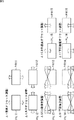
図1は、本発明を適用した画像処理装置のハードウェアの一実施の形態の構成例を示している。図1の画像処理装置11は、カメラ21−1,21−2のそれぞれにより撮像された画像より、各画素の画素値を撮像位置から被写体までの距離に反比例した値としたディスパリティ画像(奥行画像)を生成する。すなわち、カメラ21−1,21−2により撮像された画像が図2の上部で示されるような画像P1である場合、画像処理装置11は、図2の下部で示されるようなディスパリティ画像P2を生成する。図2の画像P1においては、画像内に人物、雲、および太陽が含まれている。これに対して、ディスパリティ画像P2は、画像P1における被写体となる人物について、身体本体より前面で、撮像位置に近い左右の手の先が明るく表示されており、手先より撮像位置より遠い身体本体はやや暗い色とされている。そして、被写体となる人物の身体より遠い雲や太陽については、十分に撮像位置から遠いため、暗い色にされている。また、画像処理装置11は、ディスパリティ画像を生成するにあたり、カメラ21−1,21−2の撮像方向のずれにより生じるディスパリティ画像のエラーを最小にするようにキャリブレーションを掛ける。
<1. First Embodiment>
[Configuration example of image processing apparatus]
FIG. 1 shows a configuration example of an embodiment of hardware of an image processing apparatus to which the present invention is applied. The
より具体的には、画像処理装置11は、カメラ21−1,21−2、画像ずれ補正部22、マッチング部23、およびずれ調整部24を備えている。カメラ21−1,21−2は、例えば、図3で示されるように、それぞれ同一の被写体を左右の異なる視点から撮像するように設定されており、それぞれ撮像した画像を画像ずれ補正部22に供給する。尚、カメラ21−1,21−2については、異なる視点から撮像できる構成であればよいので、図3で示されるように左右の異なる視点からではなく、例えば、上下に異なる視点からであってもよい。また、複数の異なる視点から撮像できる構成であればよいので、2個のカメラにより2点の異なる視点からの画像でなくてもよく、それ以上の複数の視点から撮像される複数の画像を用いるようにしてもよい。ただし、以降においては、説明の便宜上、左右の異なる視点から撮像される2個のカメラ21−1,21−2であるものとして説明を進めるものとする。
More specifically, the
画像ずれ補正部22は、カメラ21−1,21−2より供給されてくる画像を、ずれ調整部24により調整されたパラメータに基づいて、画像を補正し、補正画像をそれぞれマッチング部23に供給する。より詳細には、画像ずれ補正部22は、射影変換部41−1,41−2、および射影変換パラメータ算出部42を備えている。射影変換パラメータ算出部42は、ずれ調整部24の調整パラメータ保存部82に保存されている調整パラメータに基づいて、射影変換パラメータを算出し、射影変換部41−1,41−2に供給する。射影変換部41−1,41−2は、射影変換パラメータに基づいて、それぞれカメラ21−1,21−2より供給されてくる画像の各画素の画素位置を変換した補正画像を生成して、マッチング部23に供給する。
The image shift correction unit 22 corrects the images supplied from the cameras 21-1 and 21-2 based on the parameters adjusted by the shift adjustment unit 24 and supplies the corrected images to the
射影変換部41−1,41−2は、具体的には、例えば、図4の画像PL1,PR1を、射影変換パラメータにより、図4の画像PL2,PR2のように変換する。図4の画像PL1は、カメラ21−1により撮像された画像であり、画像PL2は、射影変換部41−1により射影変換され、補正された補正画像を示している。また、同様に、図4の画像PR2は、カメラ21−2により撮像された画像であり、画像PR2は、射影変換部41−2により射影変換され、補正された補正画像を示している。すなわち、射影変換元の4頂点の各座標(x_left[n],y_left[n])に対応する、射影変換先の座標は(X_left[n],Y_left[n])と表されるものとする。なお、nは頂点4点を識別する識別子とされており0≦n<3である。 Specifically, for example, the projective conversion units 41-1 and 41-2 convert the images PL1 and PR1 in FIG. 4 to the images PL2 and PR2 in FIG. 4 using the projective conversion parameters. An image PL1 in FIG. 4 is an image captured by the camera 21-1, and an image PL2 is a corrected image that has undergone projective conversion by the projective conversion unit 41-1, and has been corrected. Similarly, an image PR2 in FIG. 4 is an image captured by the camera 21-2, and the image PR2 indicates a corrected image that has undergone projective conversion by the projective conversion unit 41-2 and has been corrected. That is, the coordinates of the projective transformation destination corresponding to the coordinates (x_left [n], y_left [n]) of the four vertices of the projective transformation source are expressed as (X_left [n], Y_left [n]). . Note that n is an identifier for identifying four vertices, and 0 ≦ n <3.
射影変換先の長方形は、カメラ画像の水平ピクセルサイズをW、垂直ピクセルサイズをHとし、以下の式(1)乃至(4)のように表され、例えば、W=320,H=240である。 The projection conversion destination rectangle is represented by the following formulas (1) to (4), where W is the horizontal pixel size of the camera image and H is the vertical pixel size. For example, W = 320 and H = 240. .

ここで、BW,BHは、水平・垂直の画面端から、長方形までのピクセル数を表し、例えば、BW=64,BH=64である。尚、式(1)乃至式(4)においては、画像PL1を画像PL2に変換する場合の例についての変換式であるが、基本的に、画像PR1を画像PR2に変換する変換式についても同様であるので、その説明は省略する。 Here, BW and BH represent the number of pixels from the horizontal and vertical screen edges to the rectangle, for example, BW = 64 and BH = 64. In addition, in Formula (1) thru | or Formula (4), although it is a conversion formula about the example in the case of converting image PL1 into image PL2, it is the same also about the conversion formula which converts image PR1 into image PR2. Therefore, the description thereof is omitted.
また、調整パラメータは、(ΔX,ΔY,ΔS0,ΔY0,ΔS1,ΔY1)で表され、上記の長方形状の画像における各頂点を射影変換するためのパラメータである。 The adjustment parameter is represented by (ΔX, ΔY, ΔS0, ΔY0, ΔS1, ΔY1), and is a parameter for projective transformation of each vertex in the rectangular image.
調整パラメータのうち、ΔX,ΔYは、それぞれ、水平方向、および垂直方向の全画面でのカメラ画像のずれを補正するパラメータである。例えば、ΔYは、正の方向に大きいとき、図5の画像PL11で示されるように、射影変換元の基準長方形をΔYだけ下側へ移動させたり、または、図5の画像PR11で示されるように、ΔYだけ上部へ移動することに対応する。このパラメータは、例えば、入力された左右カメラ画像の左側が右側に対し理想的な状態から画像全体でnピクセル下へずれている場合は、ΔY=nとすることで、左右画像間の上下ずれを補正することができる。同様に、ΔXに関しては、図5の画像PL12,PR12で示されるように、左右のずれを補正するパラメタとなる。 Among the adjustment parameters, ΔX and ΔY are parameters for correcting the shift of the camera image on the entire screen in the horizontal direction and the vertical direction, respectively. For example, when ΔY is large in the positive direction, the reference rectangle of the projective transformation source is moved downward by ΔY as shown in the image PL11 of FIG. 5, or as shown in the image PR11 of FIG. Furthermore, it corresponds to moving upward by ΔY. For example, when the left side of the input left and right camera images is shifted from the ideal state to the right side by n pixels below the entire image, ΔY = n is set as the vertical shift between the left and right images. Can be corrected. Similarly, ΔX is a parameter for correcting the left / right deviation as shown by the images PL12 and PR12 in FIG.
調整パラメータΔS0、ΔY0、ΔS1、ΔY1は、上部の傾きおよび上部の垂直方向のオフセット、並びに、下部の傾きおよび下部の垂直方向のオフセットを合わせるパラメタである。後述する、2枚の補正画像のステレオマッチングにおいては、垂直方向のわずか(サブピクセル精度)でもズレがあると、マッチングがうまくいかずエラーとして現れることが知られている。そこで、画像中の上部と下部について別々に調整する。すなわち、調整パラメータΔS0により、図5の画像PL13,PR13で示されるように、上部の傾きを調整し、調整パラメータΔS1により、図5の画像PL14,PR14で示されるように、下部の傾きを調整する。また、画像中の上部と下部について別々に、調整パラメータΔY0により、図5の画像PL15,PR15で示されるように、上部のオフセットを調整し、調整パラメータΔY1により、図5の画像PL16,PR16で示されるように、下部のオフセットを調整する。 The adjustment parameters ΔS0, ΔY0, ΔS1, and ΔY1 are parameters that match the upper inclination and the upper vertical offset, and the lower inclination and the lower vertical offset. In stereo matching of two corrected images, which will be described later, it is known that if there is a slight deviation in the vertical direction (sub-pixel accuracy), matching will not be successful and an error will appear. Therefore, the upper and lower parts in the image are adjusted separately. That is, the upper inclination is adjusted as shown by the images PL13 and PR13 in FIG. 5 by the adjustment parameter ΔS0, and the lower inclination is adjusted by the adjustment parameter ΔS1 as shown by the images PL14 and PR14 in FIG. To do. Also, the upper and lower portions of the image are separately adjusted with the adjustment parameter ΔY0 as shown by the images PL15 and PR15 in FIG. 5, and the upper offset is adjusted, and the adjustment parameter ΔY1 and the images PL16 and PR16 in FIG. Adjust the bottom offset as shown.
そして、調整パラメータ(ΔX,ΔY,ΔS0,ΔS1,ΔY0,ΔY1)は、ずれ調整部24において、マッチング部23におけるディスパリティ画像におけるエラーが最小となるように調整されている。射影変換元の4頂点の各座標(x_left[n],y_left[n])は、これらの調整パラメータ(ΔX,ΔY,ΔS0,ΔS1,ΔY0,ΔY1)と、射影変換先の座標(X_left[n],Y_left[n])とにより以下の式(5)乃至式(12)のように表されることになる。
The adjustment parameters (ΔX, ΔY, ΔS0, ΔS1, ΔY0, ΔY1) are adjusted by the shift adjustment unit 24 so that the error in the disparity image in the
上のようにして求めた、左右の射影変換元と射影先の座標をそれぞれ(x,y)、(X,Y)に置き換えると、次のように、射影変換パラメタa,b,c,d,e,f,g,hを用いて、以下の式(13),式(14)で表すことができる。 When the coordinates of the left and right projection transformation sources and projection destination obtained as described above are replaced with (x, y) and (X, Y), respectively, the projection transformation parameters a, b, c, d are as follows: , e, f, g, h can be expressed by the following equations (13) and (14).
上記の式は、射影変換前の座標(x,y)と射影変換後の座標 (X,Y)をそれぞれ(xn,yn),(Xn,Yn)(nは0,1,2,3)とし、射影変換パラメータをP=(a,b,c,d,e,f,g,h)とおくと、以下の式(15)のように変形することができる。 The above equation, before projection transformation coordinates (x, y) and coordinates (X, Y) after the projection conversion for each (x n, y n), (X n, Y n) (n is 0, 1, 2 and 3) and projective transformation parameters P = (a, b, c, d, e, f, g, h), the following equation (15) can be transformed.
上述した式(15)の(xn,yn)へ、x_left[n],y_left[n]の座標を代入し、(Xn,Yn)へX_left[n],Y_left[n]を代入することによって、射影変換パラメータPを、それぞれ連立方程式の解として求めることができる。 Substituting the coordinates of x_left [n] and y_left [n] into (x n , y n ) in equation (15) above, and substituting X_left [n] and Y_left [n] into (X n , Y n ) By doing so, the projective transformation parameters P can be obtained as solutions of simultaneous equations, respectively.
以下、上記で求めた左画像用、右画像用の射影変換パラメータPは、それぞれ、Pleft,Prightとする。 Hereinafter, the left and right image projection transformation parameters P obtained above are Pleft and Pright, respectively.
すなわち、射影変換部41−1,41−2は、上述したように求めた、射影変換パラメータPleft,Prightに基づいて、カメラ21−1,21−2のそれぞれで撮像された画像に対して、式(13),式(14)による射影変換処理を行い、補正画像を生成する。尚、射影変換での画素値の対応付けについては、エイリアシングの発生を抑えるため、バイリニア法、バイキュービック法等による、周辺画素を用いた画素補間を行うことが望ましい。 That is, the projection conversion units 41-1 and 41-2 are based on the projection conversion parameters Pleft and Pright obtained as described above, and the images captured by the cameras 21-1 and 21-2 are Projective transformation processing is performed according to equations (13) and (14) to generate a corrected image. In association with pixel values in projective transformation, it is desirable to perform pixel interpolation using peripheral pixels by a bilinear method, a bicubic method, or the like in order to suppress the occurrence of aliasing.
マッチング部23は、画像ずれ補正部22より供給されてくる視点の異なるカメラ21−1,21−2により撮像された画像が調整パラメータに基づいて補正された画像を用いて、ディスパリティ画像を生成する。また、マッチング部23は、ディスパリティ画像のエラーを評価するマッチング評価値を計算して、ずれ調整部24に供給する。
The matching
より詳細には、マッチング部23は、垂直エッジ検出部61−1,61−2、およびステレオマッチング部62を備えている。垂直エッジ検出部61−1,61−2は、それぞれカメラ21−1,21−2により撮像された画像に対応する補正画像に対して、エッジ検出フィルタ処理をすることによりエッジ検出画像を生成してステレオマッチング部62に供給する。ステレオマッチング部62は、カメラ21−1,21−2により撮像された画像に対応するエッジ検出画像を用いてステレオマッチング処理を実行し、ディスパリティ画像を生成すると共に、ディスパリティ画像のエラーを評価するマッチング評価値を算出する。
More specifically, the matching
より詳細には、ステレオマッチング部62は、類似度計算部101、ペナルティ計算部102、コスト計算部103、マッチング評価値計算部104、およびディスパリティ計算部105を備えている。類似度計算部101は、2枚のエッジ検出画像の類似度similarityを計算する。ペナルティ計算部102は、隣接する画素間のディスパリティの変化に対するペナルティpenaltyを計算により求める。コスト計算部103は、2枚のエッジ検出画像の水平方向のライン毎の類似度similarityとペナルティpenaltyとを加算することによりコストcostを計算する。マッチング評価値計算部104は、全てのライン毎のコストcostの総和をマッチング評価値errorとして計算する。ディスパリティ計算部105は、コストcostを最小にするときの各画素のディスパリティdispalityを求め、ディスパリティ画像として出力する。
More specifically, the stereo matching unit 62 includes a
ずれ調整部24は、マッチング評価値errorが最小となるように、調整パラメータ(ΔX,ΔY,ΔS0,ΔS1,ΔY0,ΔY1)を更新する。より詳細には、ずれ調整部24は、調整パラメータ更新部81、および調整パラメータ保存部82を備えている。調整パラメータ更新部81は、調整パラメータ(ΔX,ΔY,ΔS0,ΔY0,ΔS1,ΔY1)を変化させながら、マッチング評価値errorを求め、マッチング評価値errorが最小となるように更新して、調整パラメータ保存部82に保存させる。
The deviation adjusting unit 24 updates the adjustment parameters (ΔX, ΔY, ΔS0, ΔS1, ΔY0, ΔY1) so that the matching evaluation value error is minimized. More specifically, the deviation adjustment unit 24 includes an adjustment
より詳細には、調整パラメータ更新部81は、簡易位置調整部121、詳細位置調整部122、および傾き調整部123を備えている。簡易位置調整部121は、調整パラメータのうち、視差の探索方向のパラメータである調整パラメータ(ΔX,ΔY)を画像の全範囲について、比較的荒い画素の間隔で、変化させて、最もマッチング評価値errorが小さくなるように、調整パラメータ(ΔX,ΔY)を調整する。詳細位置調整部122は、簡易位置調整部121により求められた調整パラメータ(ΔX,ΔY)の近傍において、画素間の間隔を徐々に小さくしながら変化させて、マッチング評価値errorが最小となるように、調整パラメータ(ΔX,ΔY)を詳細に調整する。傾き調整部123は、調整パラメータのうち、視差の探索方向に対して直交する方向のパラメータである調整パラメータ(ΔS0,ΔY0,ΔS1,ΔY1)を、調整パラメータΔS0→ΔY0→ΔS1→ΔY1→・・の順序で徐々に変化の間隔を小さくしながら繰り返して、マッチング評価値errorが最小となるように、調整パラメータ(ΔS0,ΔY0,Δ
S1,ΔY1)を調整する。
More specifically, the adjustment
Adjust S1, ΔY1).
すなわち、画像処理装置11においては、ずれ調整部24により調整された調整パラメータにより、画像ずれ補正部22が、カメラ21−1,21−2により撮像される画像を補正して、補正画像としてマッチング部23に供給する。そして、マッチング部23が、2枚の補正画像に基づいてステレオマッチング処理によりディスパリティ画像を生成すると共に、マッチング評価値errorを算出する。ずれ調整部24が、このマッチング評価値errorを最小にするように、調整パラメータを更新する。この一連の処理が繰り返されることにより、マッチング評価値errorが最小となるところで、調整パラメータが収束し、キャリブレーションが完了し、以降においては、高い精度でディスパリティ画像を生成することが可能となる。
That is, in the
[キャリブレーション処理]
次に、図6のフローチャートを参照して、キャリブレーション処理について説明する。
[Calibration process]
Next, the calibration process will be described with reference to the flowchart of FIG.
ステップS1において、ずれ調整部24の調整パラメータ更新部81は、調整パラメータ(ΔX,ΔY,ΔS0,ΔY0,ΔS1,ΔY1)の基準となるベース調整量(ΔXbase,ΔYbase,ΔS0base,ΔY0base,ΔS1base,ΔY1base)を、調整パラメータとして取り得る値のいずれかに初期化する。初期化する値としては、例えば、調整パラメータとして取り得る値の範囲の最小値、または最大値などである。
In step S1, the adjustment
ステップS2において、調整パラメータ更新部81は、簡易位置調整部121を制御して、簡易位置調整処理を実行させて、簡易的にマッチング評価値errorが小さくなる概略の調整パラメータ(ΔX,ΔY)を求める。
In step S2, the adjustment
[簡易位置調整処理]
ここで、図7のフローチャートを参照して、簡易位置調整処理について説明する。
[Simple position adjustment processing]
Here, the simple position adjustment process will be described with reference to the flowchart of FIG.
ステップS21において、簡易位置調整部121は、エラー最小値error_minを定義して、初期化すると共に、調整パラメータであるΔX,ΔY,ΔS0,ΔY0,ΔS1,ΔY1の調整変数ΔX’,ΔY’,ΔS0’,ΔY0’,ΔS1’,ΔY1’を初期化する。より具体的には、簡易位置調整部121は、エラー最小値error_minとして考えられる最大値を代入すればよく、例えば、エラー最小値error_min=0xffffffffとするようにしてもよい。尚、簡易位置調整処理においては、調整パラメータのうちΔX,ΔYのみしか扱わないため、この調整パラメータのみが初期化されれば、その他の値は、所定の値に設定されているのみでもよい。
In step S21, the simple
ステップS22において、簡易位置調整部121は、調整パラメータ(ΔX,ΔY,ΔS0,ΔY0,ΔS1,ΔY1)を、調整変数(ΔX’,ΔY’,ΔS0’,ΔY0’,ΔS1’,ΔY1’)を用いて計算し更新し、調整パラメータ保存部82に保存する。すなわち、簡易位置調整部121は、調整パラメータのそれぞれについて、ベース調整量に調整変数の値を加算することにより(ΔX=ΔXbase+ΔX’,ΔY=ΔYbase+ΔY’,ΔS0=ΔS0base+ΔS0’,ΔY0=ΔY0base+ΔY0’,ΔS1=ΔS1base+ΔS1’,ΔY1=ΔY1base+ΔY1’)計算し、更新する。ここで、(ΔXbase,ΔYbase,ΔS0base,ΔY0base,ΔS1base,ΔY1base)は、それぞれ調整パラメータ(ΔX,ΔY,ΔS0,ΔY0,ΔS1,ΔY1)のベース調整量である。
In step S22, the simple
ステップS23において、画像ずれ補正部22の射影変換パラメータ算出部42は、調整パラメータ保存部82に保存されている調整パラメータ(ΔX,ΔY,ΔS0,ΔY0,ΔS1,ΔY1)を読み出して、上述した式(13),式(14)により射影変換パラメータPを算出し、射影変換部41−1,41−2に供給する。
In step S23, the projection conversion
ステップS24において、射影変換部41−1,41−2は、射影変換パラメータPに基づいて、カメラ21−1,21−2より供給されてくる画像を射影変換することで、補正画像を生成し、マッチング部23に供給する。
In step S24, the projective conversion units 41-1 and 41-2 generate a corrected image by performing projective transform on the images supplied from the cameras 21-1 and 21-2 based on the projective transformation parameter P. , Supplied to the
ステップS25において、マッチング部23の垂直エッジ検出部61−1,61−2は、画像ずれ補正部22の射影変換部41−1,41−2のそれぞれから供給されてくる補正画像に垂直エッジ検出フィルタにより処理を施して、垂直エッジを検出する。そして、垂直エッジ検出部61−1,61−2は、それぞれ検出した垂直エッジからなるエッジ検出画像をステレオマッチング部62に供給する。
In step S25, the vertical edge detection units 61-1 and 61-2 of the
より詳細には、垂直エッジ検出部61−1,61−2は、入力されたカメラ21−1,21−2により撮像された画像が画像ずれ補正部22により補正された補正画像のDC(Direct Current)のオフセット成分による左右間の差異の影響をなくすために、ステレオマッチングにおいて必要な水平方向のエッジ情報の抽出をおこなった、エッジ画像を生成する。垂直エッジ検出部61−1,61−2は、入力された補正画像の各画素を注目画素とするとき、例えば、その注目画素を中心として、3画素×3画素の方形のSobelフィルタによる処理を施す。より具体的には、垂直エッジ検出部61−1,61−2は、以下の式(16)で示される演算により、入力画像の注目画素の輝度値をg(x,y)、出力画像の輝度値をf(x,y)として演算する。 More specifically, the vertical edge detection units 61-1 and 61-2 perform DC (Direct) of a corrected image obtained by correcting the images captured by the input cameras 21-1 and 21-2 by the image shift correction unit 22. In order to eliminate the influence of the difference between the left and right due to the offset component of (Current), an edge image is generated by extracting horizontal edge information necessary for stereo matching. When the vertical edge detection units 61-1 and 61-2 use each pixel of the input corrected image as a target pixel, for example, the vertical edge detection units 61-1 and 61-2 perform processing by a 3 pixel × 3 pixel square Sobel filter with the target pixel as the center. Apply. More specifically, the vertical edge detection units 61-1 and 61-2 obtain the luminance value of the target pixel of the input image as g (x, y) and the output image by the calculation represented by the following equation (16). The luminance value is calculated as f (x, y).
ここで、hは、例えば、以下の式(17)で示されるSobelフィルタを示す行列式である。 Here, h is, for example, a determinant indicating a Sobel filter expressed by the following equation (17).
ステップS26において、ステレオマッチング部62は、供給されてきたカメラ21−1,21−2によりそれぞれ撮像された画像に対応するエッジ検出画像を用いてステレオマッチング処理を実行することにより、マッチング評価値errorを算出すると共に、ディスパリティ画像を生成する。 In step S <b> 26, the stereo matching unit 62 performs stereo matching processing using the edge detection images corresponding to the images captured by the supplied cameras 21-1 and 21-2, thereby matching evaluation value error And a disparity image is generated.
[ステレオマッチング処理]
ここで、図8のフローチャートを参照して、ステレオマッチング処理について説明する。
[Stereo matching processing]
Here, the stereo matching process will be described with reference to the flowchart of FIG.
尚、ここでは、カメラ21−1,21−2により撮像された画像のうち、左画像を基準としたときの、右画像の対応点までのディスパリティを求める例を示すものとする。また、左画像をp(x,y),右画像をq(x,y)とし、求めるディスパリティは、disparity(x,y)(0≦disparity(x,y)≦d_max)とする。d_maxは、求めるディスパリティの最大値であり、例えば、d_max=63である。 Here, an example in which disparity to the corresponding point of the right image when the left image is used as a reference among images captured by the cameras 21-1 and 21-2 is shown. Also, the left image is p (x, y), the right image is q (x, y), and the disparity to be calculated is disparity (x, y) (0 ≦ disparity (x, y) ≦ d_max). d_max is the maximum value of disparity to be obtained, and for example, d_max = 63.
ステップS51において、類似度計算部101は、左右画像間の類似度を表すsimilarity(x,y,d)を以下の式(18)を計算する。
In step S51, the
尚、類似度similarity(x,y,d)を求める式(18)においては、3画素×3画素のブロック領域の輝度差の差分絶対値和(SAD)を用いる例が示されているが、このブロックサイズには限定されるものではない。また、類似度similarity(x,y,d)を求めるにあたっては、差分絶対値和(SAD)ではなく、差分二乗和(SSD)等が用いられる計算であってもよい。また、ここで、dは、水平方向のずれ量である。 Note that, in the equation (18) for calculating the similarity similarity (x, y, d), an example is shown in which the sum of absolute differences (SAD) of the luminance difference of the block area of 3 pixels × 3 pixels is used. The block size is not limited. Further, in calculating similarity (x, y, d), the calculation may use a sum of squared differences (SSD) or the like instead of a sum of absolute differences (SAD). Here, d is the amount of deviation in the horizontal direction.
ステップS52において、ペナルティ計算部102は、ディスパリティdisparity(x,y)は滑らかに変化するという制約を加えるペナルティを計算する。より詳細には、ペナルティ計算部102は、水平方向に隣合う画素のディスパリティ値をd0,d1とするとき、以下の式(19)のように定義する。
In step S52, the
ここで、λは、ディスパリティの変化量の絶対値に比例してペナルティを変化させる重みであり、例えば、λ=5などである。尚、式(19)は、必ずしも比例式でなくてもよく、ディスパリティdisparity(x,y)の変化量に応じて増加する関数であればよい。 Here, λ is a weight for changing the penalty in proportion to the absolute value of the disparity change amount, and for example, λ = 5. Note that equation (19) does not necessarily have to be a proportional equation, and may be a function that increases according to the amount of change in disparity disparity (x, y).
ステップS53において、コスト計算部103は、各ライン(y=0)毎に、x=0からx=W−1の間において、左右画像間の類似度similarity(x,y,d)とディスパリティ値の連続性に関するペナルティpenalty(d0,d1)を加算していったときのコスト関数を以下の式(20)のように計算する。
In step S53, the
ステップS54において、ディスパリティ計算部105は、式(20)を計算することにより、ディスパリティを計算する。より詳細には、ディスパリティ計算部105は、例えば、x=0から、x=W-1までのディスパリティを求める場合、cost_min(W−1,y)を最小化することによって、各ピクセルのディスパリティdisparity(x,y)を求める。この最小化計算に関しては、動的計画法(Dynamic Programming)を用いることによって比較的少ない演算量で実現することが可能である。このような、ステレオマッチングのディスパリティ算出のために、上記と同様に動的計画法を使用する例は、現在は、広く知られている。動的計画法を用いたステレオマッチングについては、例えば、Yuichi Ohta, Takeo Kanade Stereo by Intra- and Inter-Scanline Search Using Dynamic Programming IEEE Transactions on Pattern Analysis and Machine Intelligence,1985を参照されたい。
In step S54, the
尚、コスト関数の定義も様々な手法があるが、上記に限定されず、ステレオマッチング処理によるエラー量に対応してコストが増加するような関数であれば、他の手法を用いてもよい。 Although there are various methods for defining the cost function, the method is not limited to the above, and other methods may be used as long as the function increases the cost corresponding to the error amount due to the stereo matching process.
ステップS55において、マッチング評価値計算部104は、以下の式(21)で示されるように、上記の式(20)で示されるcost_min(x,y)の全ラインでの総和をマッチング処理における評価値errorとして計算し、ずれ調整部24に供給する。
In step S55, the matching evaluation
ただし、画像端部分は、対応点の欠落等で統計的に正しい情報が少ないので、ピクセル単位での類似度とペナルティ量の和を求め、全画面で重み付けを行いながらその総和を求めて、これを評価値としてもよい。 However, since there is little statistically correct information at the edge of the image due to missing corresponding points, etc., the sum of the similarity and penalty amount in pixel units is obtained, and the sum is obtained while weighting the entire screen. May be used as the evaluation value.
すなわち、画素単位でのコストcost(x,y)は、以下の式(22)のように表される。 That is, the cost cost (x, y) in pixel units is expressed as the following equation (22).
そこで、マッチング評価値計算部104は、式(22)で表されるコストcost(x,y)に対して、画面端部の寄与が下がるように重み付けし、さらに、積分することにより、以下の式(23)で示されるように計算するようにしてもよい。このようにすることで、マッチング評価値計算部104は、重み付けにより画像端部分の寄与を小さくしたマッチング評価値を計算することが可能となる。
Therefore, the matching evaluation
ここで、weight(a)は、重み付け関数であり、例えば、以下の式(24)で示すような関数としてもよい。 Here, weight (a) is a weighting function, and may be a function as shown by the following equation (24), for example.
ここで、引数のaは、有効画素の位置(x,y)を、水平もしくは垂直軸上で0から1.0で表している。なお、重み付けの方法としては、端部の寄与が下がるようなものであれば、その他の関数であってもよいものである。 Here, the argument a represents the position (x, y) of the effective pixel from 0 to 1.0 on the horizontal or vertical axis. As the weighting method, any other function may be used as long as the contribution of the end portion is reduced.
なお、上記においては、左画像を基準として右画像の対応を求めるステレオマッチングの結果を求める例について説明してきたが、同様に右画像を基準として左画像の対応を求めることができる。そこで、マッチング評価値計算部104は、これらを用いて、左右それぞれを基準としたマッチング評価値を、error_left_base,error_right_baseとし、それらの和を以下の式(25)で示すように定義して求め、これをマッチング評価値してもよい。このように左右それぞれを基準としたステレオマッチングを行うことにより、互いに死角となり参照できない領域(オクリュージョン)部分の評価値を上乗せできるため、評価値としての特性をより向上させることが可能となる。
In the above description, the example of obtaining the result of stereo matching for obtaining the correspondence of the right image on the basis of the left image has been described. Similarly, the correspondence of the left image can be obtained on the basis of the right image. Therefore, the matching evaluation
ここで、図7のフローチャートの説明に戻る。 Now, the description returns to the flowchart of FIG.
ステップS27において、ずれ調整部24における調整パラメータ更新部81の簡易位置調整部121は、求められたマッチング評価値errorが、今現在のエラー最小値error_minよりも小さいか否かを判定する。ステップS27において、マッチング評価値errorが、エラー最小値error_minよりも小さい場合、最小値が更新されたものとみなし、処理は、ステップS28に進む。
In step S27, the simple
ステップS28において、簡易位置調整部121は、このときの調整パラメータ(ΔX,ΔY,ΔS0,ΔY0,ΔS1,ΔY1)を調整パラメータの最小値(ΔXmin,ΔYmin,ΔS0min,ΔY0min,ΔS1min,ΔY1min)として記憶する。このとき、簡易位置調整部121は、エラー最小値error_minを、今現在のマッチング評価値errorに更新する。
In step S28, the simple
一方、ステップS27において、マッチング評価値errorがエラー最小値error_minよりも小さくない場合、ステップS28の処理はスキップされる。 On the other hand, if the matching evaluation value error is not smaller than the minimum error value error_min in step S27, the process of step S28 is skipped.
ステップS29において、簡易位置調整部121は、調整変数のうち、ΔX’,ΔY’で定義される、マッチング評価値errorの最小値の探索範囲のうち、未処理の探索範囲が残っているか否かを判定する。調整変数ΔX’,ΔY’,ΔS0’,ΔY0’,ΔS1’,ΔY1’の探索範囲は、それぞれ、ΔX’min乃至ΔX’max,ΔY’min乃至ΔY’max,ΔS0’min乃至ΔS0’max,ΔY0’min乃至ΔY0’max,ΔS1’min乃至ΔS1’max,ΔY1’min乃至ΔY1’maxで表現されることになる。そこで、調整変数ΔX’,ΔY’,ΔS0’,ΔY0’,ΔS1’,ΔY1’の探索範囲は、それぞれΔX’min≦ΔX’≦ΔX’max,ΔY’min≦ΔY’≦ΔY’max,ΔS0’min≦ΔS0’≦ΔX’max,ΔY0’min≦ΔY0’≦Y0’max,ΔS1’min≦ΔS1’≦ΔX’max,ΔY1’min≦ΔY1’≦Y1’maxのように定義される。
In step S29, the simple
ステップS29において、探索範囲が残されていると判定された場合、ステップS30において、簡易位置調整部121は、調整変数(ΔX’,ΔY’)を未処理の探索範囲のものに更新し、処理は、ステップS22に戻る。
If it is determined in step S29 that the search range remains, in step S30, the simple
すなわち、例えば、探索範囲における探索対象となる画素が、図9で示されるように定義される場合、図中の左上の丸印で示される画素SL1から矢印の順序でSLmまで順次設定される。このとき、探索変数ΔX’,ΔY’の探索間隔をΔX’step,ΔY’stepとすれば、ΔX’min乃至ΔX’maxにおいては、ΔX’=ΔX’+ΔX’stepにより順次更新され、X’maxになると、ΔY’=ΔY’+ΔY'stepにより更新されて、ΔX’=ΔX’minとされ、ΔY’min乃至ΔY’maxの範囲で同様の処理が繰り返されて、X’=X’maxで、かつ、Y’=Y’maxのとき処理が終了することになる。 That is, for example, when pixels to be searched in the search range are defined as shown in FIG. 9, the pixels are sequentially set from pixel SL1 indicated by the upper left circle in the figure to SLm in the order of the arrows. At this time, if the search intervals of the search variables ΔX ′ and ΔY ′ are ΔX′step and ΔY′step, ΔX ′ = ΔX ′ + ΔX′step is sequentially updated from ΔX′min to ΔX′max. When it reaches' max, it is updated by ΔY '= ΔY' + ΔY'step, ΔX '= ΔX'min, and the same processing is repeated in the range of ΔY'min to ΔY'max, and X' = X When 'max' and Y '= Y'max, the process is terminated.
そして、ステップS29において、探索範囲が残されていないと判定された場合、処理は、ステップS31に進む。 If it is determined in step S29 that no search range remains, the process proceeds to step S31.
ステップS31において、簡易位置調整部121は、エラー最小値error_minにおける調整パラメータの最小値(ΔXmin,ΔYmin,ΔS0min,ΔY0min,ΔS1min,ΔY1min)に基づいて、ベース調整量(ΔXbase,ΔYbase,ΔS0base,ΔY0base,ΔS1base,ΔY1base)を更新する。すなわち、簡易位置調整部121は、ベース調整量(ΔXbase,ΔYbase)を、エラー最小値error_minにおける調整パラメータの最小値(ΔXmin,ΔYmin)に設定し、処理を終了する。
In step S31, the simple
すなわち、以上の処理により、画像の全範囲において、マッチング評価値errorが最小となる調整パラメータ(ΔX,ΔY)となる、概ねの位置をベース調整量(ΔXbase,ΔYbase)として求めることが可能となる。 That is, by the above processing, it is possible to obtain an approximate position as the base adjustment amount (ΔXbase, ΔYbase) that is the adjustment parameter (ΔX, ΔY) that minimizes the matching evaluation value error in the entire range of the image. .
ここで、図6のフローチャートの説明に戻る。 Now, the description returns to the flowchart of FIG.
ステップS3において、調整パラメータ更新部81の詳細位置調整部122は、簡易位置調整処理により簡易的に求められた概略の調整パラメータ(ΔX,ΔY)に基づいて、詳細位置調整処理を実行し、より詳細にマッチング評価値errorが最小となる概略の調整パラメータ(ΔX,ΔY)を求める。
In step S3, the detailed
[詳細位置調整処理]
ここで、図10のフローチャートを参照して、詳細位置調整処理について説明する。
[Detailed position adjustment processing]
Here, the detailed position adjustment processing will be described with reference to the flowchart of FIG.
ステップS81において、詳細位置調整部122は、後述する繰り返し回数をカウントするカウンタrを初期化する。
In step S81, the detailed
ステップS82において、詳細位置調整部122は、直前の処理でエラー最小値error_minとなる調整パラメータ(ΔX,ΔY)の近傍に縮小した探索範囲を設定する。
In step S82, the detailed
ステップS83において、詳細位置調整部122は、探索変数ΔX’,ΔY’の探索間隔を、探索範囲に対応付けて縮小する。
In step S83, the detailed
すなわち、図11の上段の丸印で示される各画素の探索範囲内において、色付きの丸印で示される画素が、1回目の処理でエラー最小値error_minとなる調整パラメータΔXまたはΔYを示す場合、詳細位置調整部122は、2回目の処理では、図11の中段の丸印が示されるように、探索画素の間隔(ΔX’stepまたはΔY’step)を小さくし、さらに、探索された1回目の処理で求められた画素の近傍の範囲を探索範囲に設定する。同様に、図11の中段の丸印で示される各画素の探索範囲内において、色付きの丸印の画素が、2回目の処理でエラー最小値error_minとなる調整パラメータΔXまたはΔYを示す場合、詳細位置調整部122は、3回目の処理では、図11の下段の丸印で示されるように、探索画素の間隔(ΔX’stepまたはΔY’step)をさらに小さくし、2回目に探索された画素の近傍の範囲を探索範囲に設定する。
That is, in the search range of each pixel indicated by the upper circle in FIG. 11, when the pixel indicated by the colored circle indicates the adjustment parameter ΔX or ΔY that becomes the error minimum value error_min in the first process, In the second process, the detailed
尚、ステップS84乃至S92の処理については、図7のステップS22乃至S30の処理と同様であるので、その説明は省略するものとする。 Note that the processing in steps S84 to S92 is the same as the processing in steps S22 to S30 in FIG.
すなわち、ステップS84乃至S92の処理により、探索範囲、および、探索変数の変化が縮小されて、マッチング評価値errorがエラー最小値error_minとなる調整パラメータ(ΔX,ΔY)が求められると、処理は、ステップS93に進む。 That is, when the search range and the change in the search variable are reduced by the processing of steps S84 to S92 and the adjustment parameter (ΔX, ΔY) at which the matching evaluation value error becomes the error minimum value error_min is obtained, Proceed to step S93.
ステップS93において、詳細位置調整部122は、繰り返し回数のカウンタrが所定回数となり、所定回数だけ探索範囲、および、探索変数の変化を縮小して、マッチング評価値errorがエラー最小値error_minとなる調整パラメータ(ΔX,ΔY)が求められたか否かを判定する。ステップS93において、例えば、繰り返し回数が所定回数ではないと判定された場合、ステップS94において、詳細位置調整部122は、カウンタrを1インクリメントして、処理は、ステップS82に戻る。すなわち、ステップS82乃至S94の処理が、所定回数だけ繰り返される。そして、ステップS93において、所定回数だけ繰り返されたと判定された場合、処理は、ステップS95に進む。
In step S93, the detailed
ステップS95において、詳細位置調整部122は、エラー最小値error_minにおける調整パラメータの最小値(ΔXmin,ΔYmin,ΔS0min,ΔY0min,ΔS1min,ΔY1min)に基づいて、ベース調整量(ΔXbase,ΔYbase,ΔS0base,ΔY0base,ΔS1base,ΔY1base)を更新する。すなわち、詳細位置調整部122は、ベース調整量(ΔXbase,ΔYbase)を、エラー最小値error_minにおける調整パラメータの最小値(ΔXmin,ΔYmin)に設定し、処理を終了する。
In step S95, the detailed
すなわち、以上の処理により、概ねの位置として求められたベース調整量(ΔXbase,ΔYbase)が求められた近傍の範囲において、所定回数だけ探索範囲、および、探索変数の変化を縮小して、マッチング評価値errorがエラー最小値error_minとなる調整パラメータ(ΔX,ΔY)が求められる処理が繰り返される。結果として、マッチング評価値errorがエラー最小値error_minとなる調整パラメータ(ΔX,ΔY)が詳細に求められ、ベース調整量(ΔXbase,ΔYbase)として格納することが可能となる。 That is, by the above processing, the change of the search range and the search variable is reduced by a predetermined number of times in the vicinity range where the base adjustment amount (ΔXbase, ΔYbase) obtained as the approximate position is obtained, and matching evaluation is performed. The process for obtaining the adjustment parameter (ΔX, ΔY) for which the value error becomes the minimum error value error_min is repeated. As a result, the adjustment parameters (ΔX, ΔY) at which the matching evaluation value error becomes the minimum error value error_min are obtained in detail and can be stored as base adjustment amounts (ΔXbase, ΔYbase).
ここで、図6のフローチャートの説明に戻る。 Now, the description returns to the flowchart of FIG.
ステップS3の詳細位置調整処理により調整パラメータ(ΔX,ΔY)が詳細に求められると、処理は、ステップS4に進む。 When the adjustment parameters (ΔX, ΔY) are obtained in detail by the detailed position adjustment process in step S3, the process proceeds to step S4.
ステップS4において、傾き調整部123は、傾き調整処理を実行することにより、マッチング評価値errorがエラー最小値error_minとなる調整パラメータ(ΔS0,ΔY0,ΔS1,ΔY1)を求める。
In step S4, the
[傾き調整処理]
ここで、図12のフローチャートを参照して、傾き調整処理について説明する。
[Tilt adjustment processing]
Here, the inclination adjustment processing will be described with reference to the flowchart of FIG.
ステップS101において、傾き調整部123は、繰り返し回数をカウントするカウンタr、および後述する調整パラメータを識別するカウンタkを0に初期化する。
In step S101, the
ステップS102において、傾き調整部123は、直前の処理でエラー最小値error_minとなる調整パラメータZ(k)(k=0乃至3)(=(ΔS0,ΔY0,ΔS1,ΔY1))の近傍に縮小した探索範囲を設定する。ここでは、調整パラメータ(ΔS0,ΔY0,ΔS1,ΔY1)を、カウンタkにより調整パラメータZ(k)(k=0乃至3)で表現するものとする。すなわち、調整パラメータZ(0)は、調整パラメータΔS0であり、調整パラメータZ(1)は、調整パラメータΔY0であり、調整パラメータZ(2)は、調整パラメータΔS1であり、調整パラメータZ(3)は、調整パラメータΔY1である。また、調整パラメータのそれぞれについて探索範囲が設定され、最初の処理においては、取り得る値の全範囲であってもよいものである。
In step S102, the
ステップS103において、傾き調整部123は、探索変数ΔS0’,ΔY0’,ΔS1’,ΔY1’の探索間隔を、探索範囲に対応付けて設定する。すなわち、上述した探索範囲ΔX’,ΔY’の探索間隔を設定した場合と同様に、探索範囲、および繰り返し回数に対応付けて縮小されて設定される。
In step S103, the
尚、ステップS104乃至S112の処理については、図7のステップS22乃至S30の処理と同様であるので、その説明は省略するものとする。 Note that the processing in steps S104 to S112 is the same as the processing in steps S22 to S30 in FIG.
すなわち、ステップS104乃至S112の処理により、探索範囲、および、探索変数の変化が縮小されて、マッチング評価値errorがエラー最小値error_minとなる調整パラメータZ(k)が求められると、処理は、ステップS113に進む。 That is, when the search range and the change in the search variable are reduced by the processing of steps S104 to S112, and the adjustment parameter Z (k) at which the matching evaluation value error becomes the error minimum value error_min is obtained, The process proceeds to S113.
ステップS113において、傾き調整部123は、カウンタkがk=3であるか否かを判定する。ステップS113において、カウンタkがk=3ではない場合、ステップS114において、カウンタkが1インクリメントされて、処理は、ステップS104に戻る。
In step S113, the
すなわち、ステップS104乃至S114の処理が繰り返されることにより、カウンタkが1インクリメントされる度に、マッチング評価値errorがエラー最小値error_minとなる調整パラメータが、ΔS0→ΔY0→ΔS1→ΔY1の順序で切り替えられて求められる。そして、ステップS113において、カウンタkがk=3、すなわち、調整パラメータΔS0,ΔY0,ΔS1,ΔY1の4種類が全て求められた場合、処理は、ステップS115に進む。 That is, by repeating the processing of steps S104 to S114, every time the counter k is incremented by 1, the adjustment parameter whose matching evaluation value error becomes the minimum error value error_min is switched in the order of ΔS0 → ΔY0 → ΔS1 → ΔY1. To be requested. In step S113, if the counter k is k = 3, that is, all four types of adjustment parameters ΔS0, ΔY0, ΔS1, and ΔY1 are obtained, the process proceeds to step S115.
ステップS115において、傾き調整部123は、繰り返し回数のカウンタrが所定回数となり、所定回数だけ探索範囲、および、探索変数の変化を縮小して、マッチング評価値errorがエラー最小値error_minとなる調整パラメータΔS0,ΔY0,ΔS1,ΔY1の4種類の全てが求められたか否かを判定する。ステップS115において、例えば、繰り返し回数が所定回数ではないと判定された場合、ステップS116において、傾き調整部123は、繰り返し回数をカウントするカウンタrを1インクリメントする。そして、ステップS117において、傾き調整部123は、調整パラメータZ(k)を識別するカウンタkを1インクリメントして、処理は、ステップS102に戻る。すなわち、ステップS102乃至S117の処理が、所定回数だけ繰り返されることにより、調整パラメータΔS0,ΔY0,ΔS1,ΔY1が、ΔS0→ΔY0→ΔS1→ΔY1の順序で切り替えられながら、探索範囲、および、探索変数の変化が縮小されて、マッチング評価値errorがエラー最小値error_minとなる調整パラメータZ(k)が求められる処理が繰り返される。そして、ステップS115において、所定回数だけ繰り返されたと判定された場合、処理は、ステップS116に進む。
In step S115, the
ステップS116において、傾き調整部123は、エラー最小値error_minにおける調整パラメータの最小値(ΔXmin,ΔYmin,ΔS0min,ΔY0min,ΔS1min,ΔY1min)に基づいて、ベース調整量(ΔXbase,ΔYbase,ΔS0base,ΔY0base,ΔS1base,ΔY1base)を更新する。すなわち、傾き調整部123は、ベース調整量(ΔS0base,ΔY0base,ΔS1base,ΔY1base)を、エラー最小値error_minにおける調整パラメータの最小値(ΔS0min,ΔY0min,ΔS1min,ΔY1min)に設定し、処理を終了する。
In step S116, the
すなわち、傾き調整部123は、図13の上部の1段目乃至4段目に対応する調整パラメータΔS0,ΔY0,ΔS1,ΔY1のそれぞれについて、ライン上に丸印で示される各画素の探索範囲内において、それぞれ色付きの丸印で示される画素が、1回目の処理でエラー最小値error_minとなる調整パラメータΔS0,ΔY0,ΔS1,ΔY1として求められた場合、2回目の処理では、図13の下部の1段目乃至4段目に対応する調整パラメータΔS0,ΔY0,ΔS1,ΔY1のそれぞれについて、ライン上に丸印で示されるように、探索画素の間隔(ΔS0’step,ΔY0’step,ΔS1’step,ΔY1’step)を小さくし、さらに、探索された画素の近傍の範囲を探索範囲に設定する。
That is, the
すなわち、以上の処理により、ベース調整量(ΔS0base,ΔY0base,ΔS1base,ΔY1base)が求められた近傍の範囲において、所定回数だけ探索範囲、および、探索変数の変化を縮小して、マッチング評価値errorがエラー最小値error_minとなる調整パラメータ(ΔS0,ΔY0,ΔS1,ΔY1)が繰り返し求めることが可能となる。結果として、マッチング評価値errorがエラー最小値error_minとなる調整パラメータ(ΔS0,ΔY0,ΔS1,ΔY1)を詳細に求めることが可能となる。 That is, by the above processing, in the range where the base adjustment amount (ΔS0base, ΔY0base, ΔS1base, ΔY1base) is obtained, the change of the search range and the search variable is reduced by a predetermined number of times, and the matching evaluation value error is The adjustment parameters (ΔS0, ΔY0, ΔS1, ΔY1) that become the error minimum value error_min can be repeatedly obtained. As a result, the adjustment parameters (ΔS0, ΔY0, ΔS1, ΔY1) with which the matching evaluation value error becomes the minimum error value error_min can be obtained in detail.
ここで、図6のフローチャートの説明に戻る。 Now, the description returns to the flowchart of FIG.
ステップS4の処理により、マッチング評価値errorがエラー最小値error_minとなる調整パラメータ(ΔS0,ΔY0,ΔS1,ΔY1)として、ベース調整量(ΔS0base,ΔY0base,ΔS1base,ΔY1base)が求められると、処理は、ステップS5に進む。 When the base adjustment amount (ΔS0base, ΔY0base, ΔS1base, ΔY1base) is obtained as an adjustment parameter (ΔS0, ΔY0, ΔS1, ΔY1) with which the matching evaluation value error becomes the error minimum value error_min by the processing in step S4, Proceed to step S5.
ステップS5において、調整パラメータ更新部81は、上述したステップS3,S4の処理により求められたベース調整量(ΔXbase,ΔYbase,ΔS0base,ΔY0base,ΔS1base,ΔY1base)を、調整パラメータ(ΔX,ΔY,ΔS0,ΔY0,ΔS1,ΔY1)として調整パラメータ保存部82に保存し、処理を終了する。
In step S5, the adjustment
例えば、上述したステップS3,S4の処理における繰り返し回数を3回であるものとした場合、調整パラメータの水平方向の範囲としては、ΔX'min=−4.0/N,ΔX'max=+4.0/Nとし、垂直方向の範囲としてはΔY'min=−2.0/N,ΔY'max=+2.0/Nとする。また、水平方向の間隔としては、ΔX'step=−1.0/Nとし、垂直方向の間隔としてはΔY'step=−0.5/N,ΔY'max=+0.5/Nのようにしてもよい。さらに、この場合、上部傾きの範囲としてはΔS0'min=−2.0/N,ΔS0'max=+2.0/Nとし、上部垂直方向の範囲としてはΔY0'min=−1.0/N,ΔY0'max=+1.0/Nとしてもよい。また、同様の場合、下部傾きの範囲としては、ΔS1'min=−2.0/N,ΔS1'max=+2.0/Nとし、下部垂直方向の範囲としてはΔY1'min=−1.0/N,ΔY1'max=+1.0/Nとするようにしてもよい。さらにこの場合、上部傾きの間隔としてはΔS0'step=0.5/N、上部垂直方向の間隔としてはΔY0'step=0.25/N、下部傾きの間隔としてはΔS1'step=0.5/N、下部垂直方向の間隔としてはΔY1'step=0.25/Nとするようにしてもよい。 For example, when the number of repetitions in the processing of steps S3 and S4 described above is 3, the adjustment parameter horizontal range is ΔX′min = −4.0 / N, ΔX′max = + 4.0 / N. In the vertical direction, ΔY′min = −2.0 / N and ΔY′max = + 2.0 / N. The horizontal interval may be ΔX′step = −1.0 / N, and the vertical interval may be ΔY′step = −0.5 / N, ΔY′max = + 0.5 / N. Further, in this case, ΔS0′min = −2.0 / N, ΔS0′max = + 2.0 / N as the range of the upper inclination, and ΔY0′min = −1.0 / N, ΔY0′max = as the range in the upper vertical direction. It may be + 1.0 / N. In the same case, the lower slope ranges are ΔS1′min = −2.0 / N, ΔS1′max = + 2.0 / N, and the lower vertical range is ΔY1′min = −1.0 / N, ΔY1 ′. It may be set to max = + 1.0 / N. Further, in this case, ΔS0'step = 0.5 / N for the upper inclination interval, ΔY0'step = 0.25 / N for the upper vertical interval, ΔS1'step = 0.5 / N for the lower inclination interval, and the lower vertical direction The interval may be ΔY1′step = 0.25 / N.
以上の処理により、ステレオ画像を撮像する画像に基づいたステレオマッチングの処理によるディスパリティ画像におけるエラーの量を評価するマッチング評価値errorが最小となるように調整パラメータを設定することが可能となるので、ステレオ画像を撮像する複数のカメラの撮像方向のずれを、調整パラメータにより調整することが可能となる。また、上述したキャリブレーション処理が実行される間も、ステレオマッチング処理が繰り返されるので、ディスパリティ画像は生成され続けるため、ディスパリティ画像を生成し続けている状態のまま、キャリブレーション処理を継続することができ、製品として製造する間に別途キャリブレーションをするための工程を設ける必要がないため、製造コストをかけることなく、ユーザが使用するだけでキャリブレーションを実現することが可能となる。また、ディスパリティ画像を生成し続けながらキャリブレーションを繰り返すことができるので、経年劣化によりカメラ21−1,21−2の光軸が変化しても、その変化に追従してキャリブレーションを掛ける事が可能となる。また、撮像された画像の全範囲を用いて得られるマッチング評価値に基づいてキャリブレーションを掛ける事ができるので、よりロバスト性の高いキャリブレーションを掛ける事が可能となる。 As a result of the above processing, the adjustment parameter can be set so that the matching evaluation value error for evaluating the amount of error in the disparity image by the stereo matching processing based on the image that captures the stereo image is minimized. In addition, it is possible to adjust the shift in the imaging direction of a plurality of cameras that capture a stereo image using the adjustment parameter. In addition, since the stereo matching process is repeated while the above-described calibration process is executed, the disparity image is continuously generated. Therefore, the calibration process is continued while the disparity image is continuously generated. In addition, since it is not necessary to provide a separate calibration process during manufacturing as a product, calibration can be realized only by the user without using manufacturing costs. In addition, since calibration can be repeated while continuously generating disparity images, even if the optical axes of the cameras 21-1 and 21-2 change due to deterioration over time, calibration can be performed following the change. Is possible. In addition, since calibration can be performed based on the matching evaluation value obtained using the entire range of the captured image, it is possible to perform calibration with higher robustness.
<2.第2の実施の形態>
[画像処理装置のその他の構成例]
以上においては、キャリブレーション処理をソフトウェアプログラムにより実現する場合について説明してきたが、カメラ21−1,21−2の撮像方向などを制御するハードウェアの動作を制御することにより実現できるようにしてもよい。図14は、ハードウェアの動作を制御してキャリブレーションできるようにした本発明を適用した画像処理装置のハードウェアのその他の形態の構成例を示している。尚、図14において、図1と同一の構成については、同一の名称、および同一の符号を付しており、その説明は適宜省略するものとする。
<2. Second Embodiment>
[Other configuration examples of image processing apparatus]
In the above description, the case where the calibration process is realized by a software program has been described. However, the calibration process may be realized by controlling the operation of hardware that controls the imaging directions of the cameras 21-1, 21-2. Good. FIG. 14 shows a configuration example of another form of hardware of an image processing apparatus to which the present invention is applied so that calibration can be performed by controlling the operation of the hardware. In FIG. 14, the same components as those in FIG. 1 are denoted by the same names and the same reference numerals, and the description thereof will be omitted as appropriate.
図14の画像処理装置11において、図1の画像処理装置11と異なる点は、画像ずれ補正部22に代えて、画像ずれ補正部151を備えた点である。
The
画像ずれ補正部22においてカメラ21−1,21−2のそれぞれの撮像画像をソフトウェアプログラムにより撮像された画像を補正して補正画像を生成していた。これに対して、画像ずれ補正部151は、カメラ21−1,21−2の撮像方向を制御して補正画像を生成する。
The image shift correction unit 22 corrects the images captured by the cameras 21-1 and 21-2 with the software program to generate corrected images. On the other hand, the image
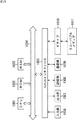
具体的には、画像ずれ補正部151は、図15の左部の矢印t1,t2で示されるように、カメラ21−1,21−2のチルト方向を制御する。また、画像ずれ補正部151は、図15の中央部の矢印p1,p2で示されるように、カメラ21−1,21−2のパン方向を制御する。さらに、画像ずれ補正部151は、図15の右部の矢印r1,r2で示されるように、カメラ21−1,21−2の回転方向を制御する。
Specifically, the image
より詳細には、画像ずれ補正部151は、光軸調整量変換部171、および光軸調整部172−1,172−2を備えている。光軸調整量変換部171は、調整パラメータ保存部82に保存されている調整パラメータ(ΔX,ΔY,ΔS0,ΔY0,ΔS1,ΔY1)に基づいて、カメラ21−1,21−2のそれぞれをチルト、パン、回転のそれぞれを制御する光軸調整量を生成する。
More specifically, the image
光軸調整部172−1,172−2は、それぞれカメラ21−1,21−2のチルト、パン、回転を物理的に制御して、カメラ21−1,21−2のそれぞれにより撮像される画像のずれを補正することで、結果として、補正画像を生成して、マッチング部23に供給する。
The optical axis adjusting units 172-1 and 172-2 physically control the tilt, pan, and rotation of the cameras 21-1 and 21-2, respectively, and are imaged by the cameras 21-1 and 21-2, respectively. By correcting the image shift, a corrected image is generated as a result and supplied to the
尚、図14の画像処理装置11におけるキャリブレーション処理については、図6のステップS2乃至S4の一部が異なるのみであるので、異なる処理についてのみ説明する。
Note that the calibration processing in the
[簡易位置調整処理]
図16のフローチャートを参照して、異なる処理である簡易位置調整処理について説明する。尚、図16のフローチャートにおいては、ステップS123,S124の処理を除いては、図7のフローチャートにおけるステップS21,S22,S25乃至S31の処理と同様であるので、その説明は省略するものとする。
[Simple position adjustment processing]
A simple position adjustment process, which is a different process, will be described with reference to the flowchart of FIG. The flowchart in FIG. 16 is the same as the processes in steps S21, S22, S25 to S31 in the flowchart in FIG. 7 except for the processes in steps S123 and S124, and the description thereof will be omitted.
すなわち、ステップS123において、光軸調整量変換部171は、調整パラメータ保存部82に保存されている調整パラメータ(ΔY,ΔY0,ΔY1)に基づいてチルトの調整量を求め、調整パラメータΔXに基づいて、パンの調整量を求め、調整パラメータ(ΔS0,ΔS1)に基づいて、回転の調整量を求める。そして、光軸調整量変換部171は、求めた調整量の情報を光軸調整部172−1,172−2に供給する。
That is, in step S123, the optical axis adjustment
ステップS124において、光軸調整部172−1,172−2は、光軸調整量変換部171からの調整量に基づいて、カメラ21−1,21−2のパン、チルト、および回転を制御することで、補正画像を生成し、マッチング部23に供給する。
In step S124, the optical axis adjustment units 172-1 and 172-2 control the pan, tilt, and rotation of the cameras 21-1 and 21-2 based on the adjustment amount from the optical axis adjustment
尚、ステップS3,S4の処理に対応する詳細位置調整処理、および傾き調整処理についても、それぞれ対応するステップS85,S86の処理、およびステップS105,S106の処理をステップS123,S124と同様の処理とすることで同様の処理を実現することが可能となる。このため、その説明は省略するものとする。 Note that the detailed position adjustment process and the inclination adjustment process corresponding to the processes in steps S3 and S4 also correspond to the processes in steps S85 and S86 and the processes in steps S105 and S106, respectively, similar to steps S123 and S124. By doing so, the same processing can be realized. Therefore, the description thereof will be omitted.
以上の処理により、図14の画像処理装置11においても、図1の画像処理装置11における場合のキャリブレーション処理と同様の効果を得ることが可能となる。
With the above processing, the
<3.第3の実施の形態>
[画像処理装置のその他の構成例]
以上においては、ステレオマッチング処理において、動的計画法などを用いてディスパリティを求めた後、マッチング評価値を計算する例について説明してきたが、動的計画法を用いたディスパリティの算出は、処理負荷が高く、これに伴って、処理時間も必要とされる。そこで、より簡易な方法でマッチング評価値errorを定義することにより、動的計画法などによるディスパリティの計算をすることなく、ステレオマッチング処理を実現するようにしてもよい。
<3. Third Embodiment>
[Other configuration examples of image processing apparatus]
In the above, in the stereo matching process, an example of calculating a matching evaluation value after obtaining disparity using dynamic programming or the like has been described, but calculation of disparity using dynamic programming is as follows: Processing load is high, and accordingly, processing time is also required. Therefore, by defining the matching evaluation value error by a simpler method, stereo matching processing may be realized without calculating disparity by dynamic programming or the like.
図17は、ステレオマッチング処理において、簡易なマッチング評価値errorを計算するようにした画像処理装置11の構成例を示している。尚、図17の画像処理装置11において、図1の画像処理装置11と同一の機能を備えた構成については、同一の名称、および同一の符号を付すものとし、その説明については適宜省略するものとする。すなわち、図17の画像処理装置11において、図1の画像処理装置11と異なるのは、マッチング部23において、垂直エッジ検出部61−1,61−2が削除されていること、および、ステレオマッチング部62において、類似度計算部101乃至ディスパリティ計算部105に代えて、コスト計算部201、マッチング評価値計算部202、およびディスパリティ計算部203が設けられた点である。
FIG. 17 shows a configuration example of the
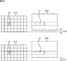
コスト計算部201は、図18で示されるように、画像ずれ補正部22より供給されてくる左右画像間におけるブロック間のマッチングエラー量の評価値を表すコストcostの最小値を、左右の画像を垂直方向にずらしながら、そのずれ量に対応付けて計算する。すなわち、図18の上段で示されるように、例えば、基準となる左画像P11が所定のサイズに分割されてブロックが設定される。そして、コスト計算部201は、例えば、図18の上段のブロックBに対応する右画像P12上の領域Z1内で、画素単位で順次水平方向にずらしながら求められるブロック間の画素間差分和をコストcostとして計算する。尚、領域Z1は、例えば、右画像P2が左画像P1に対して、垂直方向にずれ量Δyだけずらされた状態において、ブロックBと同じ高さで、かつ、左画像P11上のブロックBの水平位置に対応する右画像P12上の範囲を含み、水平方向にブロックBよりも長い範囲として設定されるものである。さらに、コスト計算部201は、図18の下段で示されるように、左画像P11に対して垂直方向に対するずれ量Δy1から、例えば、ずれ量Δy2まで、画素単位で変化させ、ずれ量Δyに応じて領域Z2を設定することで順次コストcostを計算し、ずれ量Δyに対応付けて記憶する。
As shown in FIG. 18, the
マッチング評価値計算部202は、まず、垂直方向のずれ量Δy毎に、基準となる左画像に設定されたブロック単位で、対応する右画像に設定された領域の中で求められた最小となるコストcostをそれぞれに求める。そして、マッチング評価値計算部202は、その全ブロックに対して求められた最小となるコストcostの、全画像分の総和を、ずれ量Δy毎のマッチング評価値errorとして計算する。マッチング評価値計算部202は、このような処理により、例えば、図19で示されるように、ずれ量Δyに対するマッチング評価値errorの変化を示す波形Wを求める。さらに、図19で示されるように、マッチング評価値計算部202は、ずれ量Δy毎のマッチング評価値errorが最小となるずれ量Δyminのマッチング評価値errorを、左画像P11を基準としたときの右画像P12に対するマッチング評価値errorとして出力する。
First, the matching evaluation
尚、ビルディングを所定の距離だけ離れた位置で撮像することにより、ビルディングの側壁に設けられた格子状の窓ガラスが映し出されるような2枚のステレオ画像の場合、ずれ量Δy毎のマッチング評価値errorとずれ量Δyとの関係は、例えば、図20で示されるような波形W1となることがある。このような場合、極小点が複数に存在することとなるため、例えば、最小値となる極小点を、基準となる左画像に対する右画像のマッチング評価値としたとき、図20においては、ずれ量Δymin1が正しいマッチング評価値errorであったとしても、より小さいずれ量Δymin2が左画像に対する右画像のマッチング評価値errorとして設定されることで、エラーが生じることがある。 In the case of two stereo images in which a grid-like window glass provided on the side wall of the building is projected by imaging the building at a predetermined distance, a matching evaluation value for each deviation amount Δy The relationship between error and deviation amount Δy may be, for example, a waveform W1 as shown in FIG. In such a case, since there are a plurality of minimum points, for example, when the minimum point that is the minimum value is used as the matching evaluation value of the right image with respect to the reference left image, in FIG. Even if Δymin1 is the correct matching evaluation value error, an error may occur because the smaller deviation amount Δymin2 is set as the matching evaluation value error of the right image with respect to the left image.
しかしながら、一般に、3Dカメラや、3Dビデオカメラ等の1の筐体に2のカメラが備えられるような機器の場合、2枚の画像のずれ量Δyは小さいと予想される。すなわち、1の筐体に2のカメラを備えた撮像機器であるような場合、カメラ間のおおよその位置は固定されているので、振動、経年劣化、または衝撃等で若干、位置関係が変化する程度であるものと予想される。そこで、1の筐体に2のカメラが備えられる場合、2枚の画像のずれ量Δyは、垂直ずれがない状態付近、すなわち、垂直ずれ量Δy=0付近に正解が存在するものとする。したがって、図20のような場合、ずれ量Δy=0に近い、ずれ量Δymin1におけるマッチング評価値errorが採用されるものとする。 However, in general, in the case of a device in which two cameras are provided in one housing such as a 3D camera or a 3D video camera, the shift amount Δy between the two images is expected to be small. That is, in the case of an imaging device having two cameras in one housing, the approximate position between the cameras is fixed, so the positional relationship changes slightly due to vibration, aging, impact, or the like. Is expected to be Therefore, when two cameras are provided in one housing, it is assumed that there is a correct amount of deviation Δy between the two images in the vicinity of a state where there is no vertical deviation, that is, in the vicinity of the vertical deviation amount Δy = 0. Accordingly, in the case of FIG. 20, it is assumed that the matching evaluation value error at the deviation amount Δymin1 close to the deviation amount Δy = 0 is employed.
ディスパリティ計算部203は、マッチング評価値計算部202により求められたマッチング評価値errorが最小となる左画像の各ブロックと、対応する右画像のブロックとの関係からなる画素間の関係から画素単位のディスパリティdispalityを求める。そして、ディスパリティ計算部203は、求められたディスパリティdispalityに基づいて、ディスパリティ画像を生成して出力する。
The
[ステレオマッチング処理]
次に、図21のフローチャートを参照して、図17の画像処理装置11によるステレオマッチング処理について説明する。
[Stereo matching processing]
Next, stereo matching processing by the
尚、図17の画像処理装置11のキャリブレーション処理と、図6を参照して説明した図1の画像処理装置11によるキャリブレーション処理とは、ステレオマッチング処理を除き略同様の処理であるので、ここでは、ステレオマッチング処理のみを説明するものとする。ただし、図17の画像処理装置11においては、垂直エッジ検出部61−1,61−2が省略されているため、いずれも左右の補正画像よりエッジ検出画像を生成する処理が省略される。すなわち、図7の簡易位置調整処理におけるステップS25、図10の詳細位置調整処理におけるステップS87、および図12の傾き調整処理におけるステップS107のそれぞれの処理が省略されることになる。
The calibration process of the
また、ここでは、カメラ21−1,21−2により撮像された画像のうち、左画像を基準としたときの、マッチング評価値、および右画像の対応点までのディスパリティを求める例を示すものとする。さらに、左画像をp(x,y),右画像をq(x,y)とし、求めるディスパリティは、disparity(x,y)(d_min≦disparity(x,y)≦d_max)とする。d_minは、求めるディスパリティの最小値であり、例えば、d_min=−63である。d_maxは、求めるディスパリティの最大値であり、例えば、d_max=63である。 In addition, here, an example is shown in which the matching evaluation value and the disparity up to the corresponding point of the right image when the left image is used as a reference among the images captured by the cameras 21-1 and 21-2 are shown. And Furthermore, the left image is p (x, y), the right image is q (x, y), and the disparity to be calculated is disparity (x, y) (d_min ≦ disparity (x, y) ≦ d_max). d_min is the minimum value of the disparity to be obtained, and for example, d_min = −63. d_max is the maximum value of disparity to be obtained, and for example, d_max = 63.
ステップS201において、コスト計算部201は、ずれ量を示すカウンタΔycをΔyc=0に初期化する。
In step S201, the
ステップS202において、コスト計算部201は、ずれ量Δycのマッチングエラー量の評価値であるマッチング評価値を算出するに当たり、基準となる左画像の各ブロック毎に、対応する右画像の参照領域に対して、水平方向にずらしながら以下の式(26)を計算してコストcost(x,y,d)を計算する。
In step S202, the
尚、コストcost(x,y,d)を求める式(26)においては、3画素×3画素のブロック領域の輝度差の差分絶対値和(SAD)を用いる例が示されているが、このブロックサイズに限定されるものではない。また、コストcost(x,y,d)を求めるにあたっては、差分絶対値和(SAD)ではなく、差分二乗和(SSD)等が用いられる計算であってもよい。また、ここで、dは、水平方向のずれ量である。 Incidentally, in the equation (26) for obtaining the cost cost (x, y, d), an example using the sum of absolute differences (SAD) of the luminance difference of the block area of 3 pixels × 3 pixels is shown. It is not limited to the block size. Further, in calculating the cost cost (x, y, d), a calculation using a sum of squared differences (SSD) or the like instead of the sum of absolute differences (SAD) may be used. Here, d is the amount of deviation in the horizontal direction.
さらに、マッチング評価値計算部202は、各ブロックについて、水平方向のずれ量dのうち、コストcost(x,y,d)が最小となるものmin(cost(x,y,d))を選び出して、全ブロックにおける総和を以下の式(27)で示されるように算出して、ずれ量Δycのマッチング評価値errorとして計算する。
Further, the matching evaluation
ステップS203において、コスト計算部201は、ずれ量Δycに対して、所定の距離(step:定数)だけ離れた近傍に存在するずれ量ΔyL(=c−step),ΔyR(=c+step)を設定する。尚、ずれ量Δyに対するマッチング評価値errorの関係については、例えば、図22で示されるように、横軸を垂直方向のずれ量とし、縦軸をずれ量毎のマッチング評価値errorとした波形を生成する必要があるため、図22で示されるような波形上におけるずれ量Δycに対して左側に設定されるずれ量がずれ量ΔyL(=c−step)として設定され、同様に、ずれ量Δycに対して右側に設定されるずれ量がΔyR(=c+step)として設定される。
In step S203, the
ステップS204において、コスト計算部201およびマッチング評価値計算部202は、それぞれ上述した式(26),式(27)を計算することにより、それぞれのずれ量ΔyL,ΔyRにおけるコストcostおよびマッチング評価値errorを算出する。
In step S204, the
ステップS205において、マッチング評価値計算部202は、以下の式(28)の関係を満たすか否かに基づいて、ずれ量ΔyL乃至ΔyRの範囲において、マッチング評価値errorの極小値を含むか否かを判定する。
In step S205, the matching evaluation
ここで、Δynは、所定の垂直方向のずれ量であり、ずれ量Δyn+i,Δyn−iは、それぞれずれ量Δynから正負の方向にそれぞれi画素だけ離れたずれ量であり、Th0は、所定の閾値である。また、ここでは、ずれ量Δyn−i,Δyn,Δyn+iは、ずれ量ΔyL,Δyc,ΔyRに対応し、iはstepに対応する(i=step)。すなわち、ずれ量を横軸として、縦軸にマッチング評価値とする波形が構成される場合、ずれ量ΔyL,Δyc,ΔyRの順にマッチング評価値errorが求められるとき、ずれ量Δycを頂点とする下に凸の波形が形成されるとき、true(極小値を含む)となり、それ以外のときfalse(極小値を含まない)とされる。したがって、例えば、図22の上段で示されるような場合、ずれ量ΔyL,Δyc,ΔyRの順に単調増加しているため、上述した式(28)の関係が満たされないので、処理は、ステップS206に進む。 Here, Δyn is a predetermined vertical shift amount, and the shift amounts Δyn + i and Δyn−i are shift amounts that are i pixels away from the shift amount Δyn in the positive and negative directions, respectively, and Th0 is a predetermined shift amount. It is a threshold value. Further, here, the shift amounts Δyn−i, Δyn, Δyn + i correspond to the shift amounts ΔyL, Δyc, ΔyR, and i corresponds to step (i = step). That is, when a waveform having the deviation amount as the horizontal axis and the vertical axis as the matching evaluation value is configured, when the matching evaluation value error is obtained in the order of the deviation amounts ΔyL, Δyc, and ΔyR, When a convex waveform is formed, the value is true (including the minimum value), otherwise it is set to false (not including the minimum value). Therefore, for example, in the case shown in the upper part of FIG. 22, since the deviation amounts ΔyL, Δyc, and ΔyR are monotonically increasing in this order, the relationship of the above equation (28) is not satisfied. move on.
ステップS206において、マッチング評価値計算部202は、ずれ量ΔyL,ΔyRのそれぞれに対応するマッチング評価値errorのうち、小さい方をずれ量ΔycとなるようにカウンタΔycを設定し、処理は、ステップS203に戻る。
In step S206, the matching evaluation
すなわち、例えば、図22の上段で示されるように、ずれ量Δyc=0の状態でずれ量Δycが設定されて、その左右にずれ量ΔyL,ΔyRが設定される場合、ずれ量ΔyL,Δyc,ΔyRの順に単調増加するとき、ずれ量ΔyL乃至ΔyRに極小値が存在しない。そこで、図22の下段で示されるように新たにずれ量ΔyL乃至ΔyRが設定される。すなわち、図22の上段においては、ずれ量ΔyL,ΔyRのうち、ずれ量ΔyLのマッチング評価値errorの方が小さいので、ずれ量ΔyLが、次のずれ量Δycに設定され、新たに設定されたずれ量Δycの前後に、新たなずれ量ΔyL,ΔyRが設定されることになる。これは、上述したようにずれ量Δycがゼロに近い極小値を、基準となる左画像に対する右画像のマッチング評価値error(基準画像に対する参照画像のマッチング評価値error)であるものとみなすようにした拘束条件に基づくものであり、順次、ずれ量Δy=0に近い位置で上述したような極小値を含む範囲が探索されるまで、ステップS203乃至S206の処理が繰り返される。 That is, for example, as shown in the upper part of FIG. 22, when the shift amount Δyc is set in a state where the shift amount Δyc = 0, and the shift amounts ΔyL and ΔyR are set to the left and right, the shift amounts ΔyL, Δyc, When monotonously increasing in the order of ΔyR, there is no minimum value in the shift amounts ΔyL to ΔyR. Therefore, the shift amounts ΔyL to ΔyR are newly set as shown in the lower part of FIG. That is, in the upper part of FIG. 22, since the matching evaluation value error of the deviation amount ΔyL is smaller of the deviation amounts ΔyL and ΔyR, the deviation amount ΔyL is set to the next deviation amount Δyc and newly set. New displacement amounts ΔyL and ΔyR are set before and after the displacement amount Δyc. As described above, as described above, the minimum value in which the deviation amount Δyc is close to zero is regarded as the matching evaluation value error of the right image with respect to the reference left image (matching evaluation value error of the reference image with respect to the reference image). The processing in steps S203 to S206 is repeated until a range including the minimum value as described above is sequentially searched at a position close to the deviation amount Δy = 0.
ステップS206において、例えば、図22の下段で示されるように、ずれ量Δycに対応して設定されたずれ量ΔyL乃至ΔyRの範囲に極小値を含むような関係となり、すなわち、ずれ量Δycのマッチング評価値を極小値とした下に凸の波形が形成されるとき、式(28)の条件が満たされるので、処理は、ステップS207に進む。 In step S206, for example, as shown in the lower part of FIG. 22, the relationship includes a minimum value in the range of the shift amounts ΔyL to ΔyR set corresponding to the shift amount Δyc, that is, matching of the shift amount Δyc. When the downward convex waveform is formed with the evaluation value as the minimum value, the condition of Expression (28) is satisfied, and thus the process proceeds to step S207.
ステップS207において、コスト計算部201、およびマッチング評価値計算部202は、ずれ量ΔyL,ΔyRに対応するずれ量Δyc−step乃至Δyc+step間に存在する全てのマッチング評価値を計算する。すなわち、図23の上段の白丸で示されるように、ずれ量Δycに対応して設定されたずれ量ΔyL,ΔyRが極小値を含むような関係となった場合、図23の下段の黒丸で示される、全てのマッチング評価値が求められる。
In step S207, the
ステップS208において、マッチング評価値計算部202は、ずれ量Δyc−step乃至Δyc+step間に存在する全てのずれ量に対するマッチング評価値のうち、最小値となるものを左画像(基準画像)に対する右画像(参照画像)のマッチング評価値errorとして採用する。すなわち、このように求められた基準画像である左画像に対する参照画像である右画像のマッチング評価値errorは、ずれ量Δy=0に最も近いずれ量であって、かつ、マッチング評価値errorの極小値が採用されることになる。したがって、例えば、図23の下段で示されるような場合、求められた全てのマッチング評価値errorのうち、ずれ量Δyminで示される位置のマッチング評価値errorが、基準画像である左画像に対する右画像のマッチング評価値errorとして採用される。
In step S <b> 208, the matching evaluation
ステップS209において、ディスパリティ計算部203は、マッチング評価値errorに採用されたずれ量Δyに対応する左右画像のブロック間の関係に基づいて、ディスパリティを計算し、計算結果に基づいて、ディスパリティ画像を生成して出力する。
In step S209, the
以上の処理により、i=stepを垂直方向のずれの最小単位に対してある程度大きく設定することで、粗めにマッチング評価値の極小値が存在する範囲を、ずれ量Δy=0に近い範囲から検索した後、検索された範囲内についてのみ、詳細に全てのずれ量Δyについてマッチング評価値errorを計算するようにすることで、高速に基準画像に対する参照画像のマッチング評価値errorを特定することが可能となる。また、以上のステレオマッチング処理においては、動的計画法などの処理負荷の大きな処理を含まないので、処理負荷を軽減することが可能となり、処理を高速化することが可能となる。尚、stepとして設定されたずれ量Δycからの距離に対して十分に小さい間隔でマッチング評価値が求められるのであれば、極小値を含む範囲が求められた後には、その範囲内において、必ずしも全てのずれ量に対するマッチング評価値を求めなくてもよい。すなわち、どのずれ量に対するマッチング評価値が、ずれ量Δy=0より最も近く、かつ、極小値であるという拘束条件を満たすものであるかが判断できればよいので、ずれ量に対するマッチング評価値を全て求める必要はなく、必要に応じて、その間隔は間引くようにしてもよい。このように、ずれ量に対するマッチング評価値を間引いて求めることで、ステレオマッチング処理の負荷をより軽減させることができ、処理速度を、より高速化することが可能となる。 With the above processing, by setting i = step to be somewhat large with respect to the minimum unit of deviation in the vertical direction, the range in which the minimum value of the matching evaluation value is roughly present is changed from the range close to the deviation amount Δy = 0. After the search, it is possible to specify the matching evaluation value error of the reference image with respect to the reference image at high speed by calculating the matching evaluation value error for all the shift amounts Δy in detail only within the searched range. It becomes possible. Further, since the above stereo matching processing does not include processing with a large processing load such as dynamic programming, the processing load can be reduced and the processing speed can be increased. If the matching evaluation value is obtained at a sufficiently small interval with respect to the distance from the deviation amount Δyc set as step, after the range including the minimum value is obtained, all the values in the range are not necessarily obtained. It is not necessary to obtain a matching evaluation value for the amount of deviation. That is, it is only necessary to determine which deviation evaluation value for the matching evaluation value is closest to the deviation amount Δy = 0 and satisfies the constraint condition that it is a minimum value, and thus all matching evaluation values for the deviation amount are obtained. It is not necessary, and the interval may be thinned out as necessary. Thus, by thinning out the matching evaluation value for the deviation amount, the load of the stereo matching process can be further reduced, and the processing speed can be further increased.
尚、以上においては、極小値を含むか否かの判定において、上述した式(28)の関係が満たされるか否かにより判定されていたが、極小値を含むか否かの判定が可能である限り、その他の方法で判定するようにしても良く、例えば、以下の式(29)で示されるような傾きの関係に基づいて、極小値を含むか否かを判定するようにしてもよい。 In the above description, whether or not the minimum value is included is determined based on whether or not the relationship of the above-described formula (28) is satisfied, but it is possible to determine whether or not the minimum value is included. As long as there is a limit, it may be determined by other methods. For example, it may be determined whether or not a minimum value is included based on the relationship of inclination as shown in the following equation (29). .
ここで、Th1は所定の閾値を示している。すなわち、式(29)においては、ずれ量Δynからずれ量Δyn+iに対しては、ずれ量に対するマッチング評価値の傾きが、所定の閾値Th1よりも大きな正の傾きであって、かつ、ずれ量Δyn−iからずれ量Δynに対しては、ずれ量に対するマッチング評価値の傾きが、所定の閾値−Th1よりも小さな負の傾きであるとき、true(極小値を含む)となり、それ以外のときfalse(極小値を含まない)とされる。 Here, Th1 represents a predetermined threshold value. That is, in equation (29), for the deviation amount Δyn + i from the deviation amount Δyn, the slope of the matching evaluation value with respect to the deviation amount is a positive gradient larger than the predetermined threshold Th1, and the deviation amount Δyn. With respect to the deviation amount Δyn from −i, true (including the minimum value) is true when the slope of the matching evaluation value with respect to the deviation amount is a negative slope smaller than the predetermined threshold −Th1, and false otherwise. (Not including the local minimum).
以上によれば、動的計画法のような負荷の大きな計算を用いることなくステレオマッチング処理を実現することができるので、処理速度を向上させることが可能となる。また、粗い精度でずれ量Δy=0を含む近傍からマッチング評価値の極小値を含む範囲をずれ量Δy=0から離れるように順次探索した後、探索された範囲内のみのマッチング評価値を詳細に求めて極小値を探索するようにしたので、ずれ量Δy=0から最も近くで、かつ、極小値となるずれ量Δyに対するマッチング評価値を、基準画像に対する参照画像とのマッチング評価値として高速で探索することが可能となる。尚、画像処理装置11の処理速度が、例えば、十分に速く、処理に余裕があるような場合、全てのずれ量Δyに対するマッチング評価値を求めた後、求められたずれ量Δyに対するマッチング評価値から、ずれ量Δy=0に最も近く、かつ、極小となるマッチング評価値を、基準画像に対する参照画像とのマッチング評価値として探索するようにしてもよい。さらに、以上においては、垂直方向のずれ量Δyについて、マッチング評価値を求める例について説明してきたが、同様に水平方向のずれ量に対してマッチング評価値を求めて、その最小値を基準画像に対する参照画像のマッチング評価値とするようにしてもよい。
According to the above, since the stereo matching process can be realized without using a heavy load calculation such as dynamic programming, the processing speed can be improved. Further, after sequentially searching the range including the minimum value of the matching evaluation value from the vicinity including the deviation amount Δy = 0 with coarse accuracy so as to be separated from the deviation amount Δy = 0, the matching evaluation value only in the searched range is detailed. Since the minimum value is searched for in this way, the matching evaluation value for the deviation amount Δy that is closest to the deviation amount Δy = 0 and becomes the minimum value is used as the matching evaluation value for the reference image with respect to the reference image. It becomes possible to search by. Note that when the processing speed of the
ところで、上述した一連の処理は、ハードウェアにより実行させることもできるが、ソフトウェアにより実行させることもできる。一連の処理をソフトウェアにより実行させる場合には、そのソフトウェアを構成するプログラムが、専用のハードウェアに組み込まれているコンピュータ、または、各種のプログラムをインストールすることで、各種の機能を実行することが可能な、例えば汎用のパーソナルコンピュータなどに、記録媒体からインストールされる。 By the way, the series of processes described above can be executed by hardware, but can also be executed by software. When a series of processing is executed by software, a program constituting the software may execute various functions by installing a computer incorporated in dedicated hardware or various programs. For example, it is installed from a recording medium in a general-purpose personal computer or the like.
図24は、汎用のパーソナルコンピュータの構成例を示している。このパーソナルコンピュータは、CPU(Central Processing Unit)1001を内蔵している。CPU1001にはバス1004を介して、入出力インタ-フェイス1005が接続されている。バス1004には、ROM(Read Only Memory)1002およびRAM(Random Access Memory)1003が接続されている。
FIG. 24 shows a configuration example of a general-purpose personal computer. This personal computer incorporates a CPU (Central Processing Unit) 1001. An input /
入出力インタ-フェイス1005には、ユーザが操作コマンドを入力するキーボード、マウスなどの入力デバイスよりなる入力部1006、処理操作画面や処理結果の画像を表示デバイスに出力する出力部1007、プログラムや各種データを格納するハードディスクドライブなどよりなる記憶部1008、LAN(Local Area Network)アダプタなどよりなり、インターネットに代表されるネットワークを介した通信処理を実行する通信部1009が接続されている。また、磁気ディスク(フレキシブルディスクを含む)、光ディスク(CD-ROM(Compact Disc-Read Only Memory)、DVD(Digital Versatile Disc)を含む)、光磁気ディスク(MD(Mini Disc)を含む)、もしくは半導体メモリなどのリムーバブルメディア1011に対してデータを読み書きするドライブ1010が接続されている。
The input /
CPU1001は、ROM1002に記憶されているプログラム、または磁気ディスク、光ディスク、光磁気ディスク、もしくは半導体メモリ等のリムーバブルメディア1011から読み出されて記憶部1008にインストールされ、記憶部1008からRAM1003にロードされたプログラムに従って各種の処理を実行する。RAM1003にはまた、CPU1001が各種の処理を実行する上において必要なデータなども適宜記憶される。
The
以上のように構成されるコンピュータでは、CPU1001が、例えば、記憶部1008に記憶されているプログラムを、入出力インタフェース1005及びバス1004を介して、RAM1003にロードして実行することにより、上述した一連の処理が行われる。
In the computer configured as described above, the
コンピュータ(CPU1001)が実行するプログラムは、例えば、パッケージメディア等としてのリムーバブルメディア1011に記録して提供することができる。また、プログラムは、ローカルエリアネットワーク、インターネット、デジタル衛星放送といった、有線または無線の伝送媒体を介して提供することができる。 The program executed by the computer (CPU 1001) can be provided by being recorded on the removable medium 1011 as a package medium, for example. The program can be provided via a wired or wireless transmission medium such as a local area network, the Internet, or digital satellite broadcasting.
コンピュータでは、プログラムは、リムーバブルメディア1011をドライブ1010に装着することにより、入出力インタフェース1005を介して、記憶部1008にインストールすることができる。また、プログラムは、有線または無線の伝送媒体を介して、通信部1009で受信し、記憶部1008にインストールすることができる。その他、プログラムは、ROM1002や記憶部1008に、あらかじめインストールしておくことができる。
In the computer, the program can be installed in the
なお、コンピュータが実行するプログラムは、本明細書で説明する順序に沿って時系列に処理が行われるプログラムであっても良いし、並列に、あるいは呼び出しが行われたとき等の必要なタイミングで処理が行われるプログラムであっても良い。 The program executed by the computer may be a program that is processed in time series in the order described in this specification, or in parallel or at a necessary timing such as when a call is made. It may be a program for processing.
また、本明細書において、システムとは、複数の構成要素(装置、モジュール(部品)等)の集合を意味し、すべての構成要素が同一筐体中にあるか否かは問わない。したがって、別個の筐体に収納され、ネットワークを介して接続されている複数の装置、及び、1つの筐体の中に複数のモジュールが収納されている1つの装置は、いずれも、システムである。 In this specification, the system means a set of a plurality of components (devices, modules (parts), etc.), and it does not matter whether all the components are in the same housing. Accordingly, a plurality of devices housed in separate housings and connected via a network and a single device housing a plurality of modules in one housing are all systems. .
なお、本技術の実施の形態は、上述した実施の形態に限定されるものではなく、本技術の要旨を逸脱しない範囲において種々の変更が可能である。 The embodiments of the present technology are not limited to the above-described embodiments, and various modifications can be made without departing from the gist of the present technology.
例えば、本技術は、1つの機能をネットワークを介して複数の装置で分担、共同して処理するクラウドコンピューティングの構成をとることができる。 For example, the present technology can take a configuration of cloud computing in which one function is shared by a plurality of devices via a network and is jointly processed.
また、上述のフローチャートで説明した各ステップは、1つの装置で実行する他、複数の装置で分担して実行することができる。 In addition, each step described in the above flowchart can be executed by being shared by a plurality of apparatuses in addition to being executed by one apparatus.
さらに、1つのステップに複数の処理が含まれる場合には、その1つのステップに含まれる複数の処理は、1つの装置で実行する他、複数の装置で分担して実行することができる。 Further, when a plurality of processes are included in one step, the plurality of processes included in the one step can be executed by being shared by a plurality of apparatuses in addition to being executed by one apparatus.
尚、本技術は、以下のような構成も取ることができる。
(1) 異なる視点から、同一の被写体を撮像する複数の画像を取得する画像取得手段と、
前記画像取得手段により取得された複数の画像を、画像ずれを補正するためのパラメータに基づいて変形し、それぞれ補正画像を生成する画像ずれ補正手段と、
前記画像ずれ補正手段により生成された複数の補正画像間の視差方向の対応付けが不能な程度を示すエラー量の全画面の積分値を評価値として算出する評価値算出手段と、
前記パラメータのうち、視差方向の対応付けに必要とされるパラメータを変化させて、前記評価値が最小となるようにパラメータを更新する更新手段と
を含む画像処理装置。
(2) 前記更新手段は、前記パラメータのうち、前記画像の全範囲において、2次元方向に荒い画素間隔でシフト量を変化させ、前記評価値が最小となるシフト量に更新し、さらに、前記荒い画素間隔でシフト量を変化させることにより探索されたシフト量近傍の範囲において、2次元方向に詳細な画素間隔でシフト量を変化させて評価値が最小となるシフト量に更新する
(1)に記載の画像処理装置。
(3)
前記更新手段は、前記パラメータのうち、前記複数の画像間の対応付けの方向である、視差の探索方向に対し直交する傾き成分を変化させて評価値が最小となる傾き成分に更新する
(1)または(2)に記載の画像処理装置。
(4) 前記更新手段は、前記パラメータのうち、前記複数の画像間の対応付けの方向である、視差の探索方向に対し直交する方向に、前記傾き成分を分割し、それぞれ個別に変化させて評価値が最小となる傾き成分に更新する
(3)に記載の画像処理装置。
(5) 前記評価値算出手段は、前記画像ずれ補正手段により生成された複数の補正画像間の視差方向の対応付けが不能な程度を示すエラー量の全画面の積分値を、前記画像の周辺部の寄与が小さくなるように評価値として算出する
(1)乃至(3)のいずれかに記載の画像処理装置。
(6) 前記評価値算出手段は、前記画像ずれ補正手段により生成された複数の補正画像間の視差方向の対応付けが不能な程度を示すエラー量の全画面の積分値を、ブロックマッチングの差分絶対値和の全画面総和として算出し、算出結果を評価値とする
(1)乃至(5)のいずれかに記載の画像処理装置。
(7) 前記評価値算出手段は、前記画像ずれ補正手段により生成された複数の補正画像間の視差方向の対応付けが不能な程度を示すエラー量の全画面の積分値を、動的計画法を用いて算出し、算出結果を評価値とする
(6)に記載の画像処理装置。
(8) 前記評価値算出手段は、前記画像ずれ補正手段により生成された複数の補正画像間の視差方向の対応付けが不能な程度を示すエラー量の全画面の積分値を、前記複数の補正画像間のずれ量毎にブロックマッチングの差分絶対値和の全画面総和として算出し、算出結果のうち、ずれ量が0に最も近い極小値を評価値とする
(6)に記載の画像処理装置。
(9) 前記評価値算出手段は、前記画像ずれ補正手段により生成された複数の補正画像間の視差方向の対応付けが不能な程度を示すエラー量の全画面の積分値を、前記複数の補正画像間のずれ量の粗い間隔毎にブロックマッチングの差分絶対値和の全画面総和として算出し、算出結果から、ずれ量が0に最も近い範囲で、かつ、極小値を含む範囲を探索した後、探索された範囲で詳細に求められる前記全画像総和の極小値を評価値とする
(8)に記載の画像処理装置。
(10) 前記評価値算出手段は、前記画像ずれ補正手段により生成された複数の補正画像のうち、基準画像と、それ以外の参照画像間の視差方向の対応付けが不能な程度を示すエラー量の全画面の積分値の総和を評価値として算出する
(1)乃至(9)のいずれかに記載の画像処理装置。
(11) 異なる視点から、同一の被写体を撮像する撮像手段をさらに含み、
前記画像取得手段は、前記撮像手段により異なる視点から、同一の被写体を撮像する複数の画像を取得し、
前記画像ずれ補正手段は、前記画像取得手段により取得された複数の画像を、画像ずれを補正するためのパラメータに基づいて、前記撮像手段における撮像方向となる光軸を動作させるようにすることで、変形し、それぞれ補正画像を生成する
(1)乃至(10)に記載の画像処理装置。
(12) 異なる視点から、同一の被写体を撮像する複数の画像を取得する画像取得手段と、
前記画像取得手段により取得された複数の画像を、画像ずれを補正するためのパラメータに基づいて変形し、それぞれ補正画像を生成する画像ずれ補正手段と、
前記画像ずれ補正手段により生成された複数の補正画像間の視差方向の対応付けが不能な程度を示すエラー量の全画面の積分値を評価値として算出する評価値算出手段と、
前記パラメータのうち、視差方向の対応付けに必要とされるパラメータを変化させて、前記評価値が最小となるようにパラメータを更新する更新手段と
を含む画像処理装置の画像処理方法であって、
前記画像取得手段における、異なる視点から、同一の被写体を撮像する複数の画像を取得する画像取得ステップと、
前記画像ずれ補正手段における、前記画像取得ステップの処理により取得された複数の画像を、画像ずれを補正するためのパラメータに基づいて変形し、それぞれ補正画像を生成する画像ずれ補正ステップと、
前記評価値算出手段における、前記画像ずれ補正ステップの処理により生成された複数の補正画像間の視差方向の対応付けが不能な程度を示すエラー量の全画面の積分値を評価値として算出する評価値算出ステップと、
前記更新手段における、前記パラメータのうち、視差方向の対応付けに必要とされるパラメータを変化させて、前記評価値が最小となるようにパラメータを更新する更新ステップと
を含む画像処理方法。
(13) 異なる視点から、同一の被写体を撮像する複数の画像を取得する画像取得手段と、
前記画像取得手段により取得された複数の画像を、画像ずれを補正するためのパラメータに基づいて変形し、それぞれ補正画像を生成する画像ずれ補正手段と、
前記画像ずれ補正手段により生成された複数の補正画像間の視差方向の対応付けが不能な程度を示すエラー量の全画面の積分値を評価値として算出する評価値算出手段と、
前記パラメータのうち、視差方向の対応付けに必要とされるパラメータを変化させて、前記評価値が最小となるようにパラメータを更新する更新手段と
を含む画像処理装置を制御するコンピュータに、
前記画像取得手段における、異なる視点から、同一の被写体を撮像する複数の画像を取得する画像取得ステップと、
前記画像ずれ補正手段における、前記画像取得ステップの処理により取得された複数の画像を、画像ずれを補正するためのパラメータに基づいて変形し、それぞれ補正画像を生成する画像ずれ補正ステップと、
前記評価値算出手段における、前記画像ずれ補正ステップの処理により生成された複数の補正画像間の視差方向の対応付けが不能な程度を示すエラー量の全画面の積分値を評価値として算出する評価値算出ステップと、
前記更新手段における、前記パラメータのうち、視差方向の対応付けに必要とされるパラメータを変化させて、前記評価値が最小となるようにパラメータを更新する更新ステップと
を含む処理を実行させるプログラム。
In addition, this technique can also take the following structures.
(1) image acquisition means for acquiring a plurality of images that capture the same subject from different viewpoints;
A plurality of images acquired by the image acquisition means, deformed based on a parameter for correcting image deviation, and an image deviation correction means for generating a corrected image respectively;
An evaluation value calculating means for calculating an integral value of an entire screen of an error amount indicating an inability to associate a parallax direction between a plurality of corrected images generated by the image deviation correcting means;
An image processing apparatus comprising: an update unit configured to change a parameter required for associating a parallax direction among the parameters and update the parameter so that the evaluation value is minimized.
(2) The update means changes the shift amount at a rough pixel interval in the two-dimensional direction in the entire range of the image among the parameters, updates the shift amount to minimize the evaluation value, and In the range near the shift amount searched by changing the shift amount with a rough pixel interval, the shift amount is updated at a detailed pixel interval in the two-dimensional direction and updated to a shift amount that minimizes the evaluation value. An image processing apparatus according to 1.
(3)
The update means updates the gradient component that minimizes the evaluation value by changing a gradient component that is orthogonal to the parallax search direction, which is a direction of association between the plurality of images, among the parameters. Or the image processing apparatus according to (2).
(4) The update unit divides the inclination component in a direction orthogonal to the parallax search direction, which is a direction of association between the plurality of images, among the parameters, and individually changes the inclination component. The image processing apparatus according to (3), wherein the inclination component is updated to a minimum evaluation value.
(5) The evaluation value calculation unit calculates an integral value of the entire screen of an error amount indicating a degree to which the parallax directions cannot be correlated between the plurality of corrected images generated by the image shift correction unit. The image processing apparatus according to any one of (1) to (3), wherein the evaluation value is calculated so that the contribution of the part is reduced.
(6) The evaluation value calculating unit calculates an integral value of the entire screen of an error amount indicating a degree in which the parallax directions cannot be correlated between the plurality of corrected images generated by the image shift correcting unit, and calculates a block matching difference. The image processing apparatus according to any one of (1) to (5), wherein the absolute value sum is calculated as a total sum of the entire screens and the calculation result is an evaluation value.
(7) The evaluation value calculation means uses the dynamic programming method to calculate the integral value of the entire screen of the error amount indicating the degree that the parallax directions cannot be correlated between the plurality of corrected images generated by the image shift correction means. The image processing apparatus according to (6), wherein the image processing apparatus calculates the evaluation result as an evaluation value.
(8) The evaluation value calculation unit may calculate an integral value of the entire screen with an error amount indicating a degree in which the parallax directions cannot be correlated between the plurality of corrected images generated by the image shift correction unit. The image processing apparatus according to (6), wherein a total value of the sum of absolute values of block matching is calculated for each shift amount between images, and a minimal value whose shift amount is closest to 0 among the calculation results is an evaluation value. .
(9) The evaluation value calculation unit may calculate an integral value of the entire screen of an error amount indicating a degree in which it is impossible to associate a parallax direction between a plurality of corrected images generated by the image shift correction unit. After calculating the total sum of the absolute values of the block matching differences for each coarse interval between the images, and after searching for the range where the amount of deviation is closest to 0 and including the minimum value The image processing device according to (8), wherein the minimum value of the total sum of all images obtained in detail within the searched range is used as an evaluation value.
(10) The evaluation value calculation unit is an error amount indicating a degree in which it is impossible to associate a parallax direction between a reference image and other reference images among a plurality of correction images generated by the image shift correction unit. The image processing apparatus according to any one of (1) to (9), wherein a sum total of integral values of all the screens is calculated as an evaluation value.
(11) It further includes imaging means for imaging the same subject from different viewpoints,
The image acquisition means acquires a plurality of images capturing the same subject from different viewpoints by the imaging means,
The image shift correction unit operates a plurality of images acquired by the image acquisition unit based on a parameter for correcting the image shift to operate an optical axis that is an image pickup direction in the image pickup unit. The image processing device according to any one of (1) to (10), wherein the image processing device is deformed to generate a corrected image.
(12) Image acquisition means for acquiring a plurality of images capturing the same subject from different viewpoints;
A plurality of images acquired by the image acquisition means, deformed based on a parameter for correcting image deviation, and an image deviation correction means for generating a corrected image respectively;
An evaluation value calculating means for calculating an integral value of an entire screen of an error amount indicating an inability to associate a parallax direction between a plurality of corrected images generated by the image deviation correcting means;
An image processing method for an image processing apparatus, comprising: update means for changing a parameter required for association of parallax directions among the parameters and updating the parameter so that the evaluation value is minimized,
An image acquisition step of acquiring a plurality of images capturing the same subject from different viewpoints in the image acquisition means;
An image shift correction step of deforming a plurality of images acquired by the image acquisition step in the image shift correction unit based on a parameter for correcting the image shift, and generating a corrected image respectively.
Evaluation in which the evaluation value calculating means calculates an integral value of the entire screen of an error amount indicating an inability to associate the parallax directions between a plurality of corrected images generated by the processing of the image shift correction step as an evaluation value A value calculation step;
An image processing method comprising: an updating step of updating a parameter so that the evaluation value is minimized by changing a parameter required for association of parallax directions among the parameters in the updating unit.
(13) Image acquisition means for acquiring a plurality of images capturing the same subject from different viewpoints;
A plurality of images acquired by the image acquisition means, deformed based on a parameter for correcting image deviation, and an image deviation correction means for generating a corrected image respectively;
An evaluation value calculating means for calculating an integral value of an entire screen of an error amount indicating an inability to associate a parallax direction between a plurality of corrected images generated by the image deviation correcting means;
A computer that controls an image processing apparatus including an update unit that changes a parameter required for associating a parallax direction among the parameters and updates the parameter so that the evaluation value is minimized.
An image acquisition step of acquiring a plurality of images capturing the same subject from different viewpoints in the image acquisition means;
An image shift correction step of deforming a plurality of images acquired by the image acquisition step in the image shift correction unit based on a parameter for correcting the image shift, and generating a corrected image respectively.
Evaluation in which the evaluation value calculating means calculates an integral value of the entire screen of an error amount indicating an inability to associate the parallax directions between a plurality of corrected images generated by the processing of the image shift correction step as an evaluation value A value calculation step;
A program for executing a process including: an update step of updating a parameter so that the evaluation value is minimized by changing a parameter required for the association of parallax directions among the parameters in the updating unit.
11 画像処理装置, 21−1,21−2 カメラ, 22 画像ずれ補正部, 23 マッチング部, 24 ずれ補正部, 41−1,41−2 射影変換部, 42 射影変換パラメータ算出部, 61−1,61−2 垂直エッジ検出部, 62 ステレオマッチング部, 81 調整パラメータ更新部, 82 調整パラメータ保存部, 101 類似度計算部, 102 ペナルティ計算部, 103 コスト計算部, 104 マッチング評価値計算部, 105 ディスパリティ計算部, 121 簡易位置調整部, 122 詳細位置調整部, 123 傾き調整部, 151 画像ずれ補正部, 171 光軸調整量変換部, 172−1,172−2 光軸調整部, 201 コスト計算部, 202 マッチング評価値計算部, 203 ディスパリティ計算部
DESCRIPTION OF
Claims (13)
前記画像取得手段により取得された複数の画像を、画像ずれを補正するためのパラメータに基づいて変形し、それぞれ補正画像を生成する画像ずれ補正手段と、
前記画像ずれ補正手段により生成された複数の補正画像間の視差方向の対応付けが不能な程度を示すエラー量の全画面の積分値を評価値として算出する評価値算出手段と、
前記パラメータのうち、視差方向の対応付けに必要とされるパラメータを変化させて、前記評価値が最小となるようにパラメータを更新する更新手段と
を含む画像処理装置。 Image acquisition means for acquiring a plurality of images capturing the same subject from different viewpoints;
A plurality of images acquired by the image acquisition means, deformed based on a parameter for correcting image deviation, and an image deviation correction means for generating a corrected image respectively;
An evaluation value calculating means for calculating an integral value of an entire screen of an error amount indicating an inability to associate a parallax direction between a plurality of corrected images generated by the image deviation correcting means;
An image processing apparatus comprising: an update unit configured to change a parameter required for associating a parallax direction among the parameters and update the parameter so that the evaluation value is minimized.
請求項1に記載の画像処理装置。 The update means changes the shift amount at a rough pixel interval in a two-dimensional direction in the entire range of the image among the parameters, updates the shift amount to minimize the evaluation value, and further, the rough pixel interval The range near the shift amount searched for by changing the shift amount in step 2 is updated to a shift amount that minimizes the evaluation value by changing the shift amount at a detailed pixel interval in a two-dimensional direction. Image processing device.
請求項1に記載の画像処理装置。 The update unit updates an inclination component having a minimum evaluation value by changing an inclination component orthogonal to a parallax search direction, which is a direction of association between the plurality of images, among the parameters. The image processing apparatus according to 1.
請求項3に記載の画像処理装置。 The updating unit divides the inclination component in a direction orthogonal to a parallax search direction, which is a direction of association between the plurality of images, among the parameters, and individually changes the evaluation value to obtain an evaluation value. The image processing device according to claim 3, wherein the image processing device is updated to a minimum inclination component.
請求項1に記載の画像処理装置。 The evaluation value calculating means calculates the integral value of the entire screen of the error amount indicating the degree of disabling the correspondence of the parallax directions between the plurality of corrected images generated by the image deviation correcting means, and the contribution of the peripheral portion of the image The image processing apparatus according to claim 1, wherein the evaluation value is calculated so as to be small.
請求項1に記載の画像処理装置。 The evaluation value calculating means calculates the integral value of the entire screen of the error amount indicating the degree of disabling the correspondence between the parallax directions between the plurality of corrected images generated by the image deviation correcting means, and calculates the sum of absolute differences of block matching. The image processing apparatus according to claim 1, wherein the image is calculated as a sum total of all the screens and the calculation result is an evaluation value.
請求項6に記載の画像処理装置。 The evaluation value calculation means uses an dynamic programming method to calculate an integral value of the entire screen of an error amount indicating a degree in which it is impossible to associate the parallax directions between a plurality of correction images generated by the image shift correction means. The image processing apparatus according to claim 6, wherein the image processing apparatus calculates and uses the calculation result as an evaluation value.
請求項6に記載の画像処理装置。 The evaluation value calculation means calculates an integral value of the entire screen of an error amount indicating a degree in which it is impossible to associate a parallax direction between a plurality of correction images generated by the image deviation correction means between the plurality of correction images. The image processing apparatus according to claim 6, wherein the total value of the sum of absolute values of block matching is calculated for each shift amount, and a minimal value whose shift amount is closest to 0 is used as an evaluation value among the calculation results.
請求項8に記載の画像処理装置。 The evaluation value calculation means calculates an integral value of the entire screen of an error amount indicating a degree in which it is impossible to associate a parallax direction between a plurality of correction images generated by the image deviation correction means between the plurality of correction images. Calculated as the total sum of the absolute values of the block matching difference for each coarse interval of the amount of deviation, and after searching the range where the amount of deviation is closest to 0 and including the minimum value, the search is performed. The image processing apparatus according to claim 8, wherein a minimum value of the total sum of all images obtained in detail within a range is used as an evaluation value.
請求項1に記載の画像処理装置。 The evaluation value calculating unit is a full screen of an error amount indicating a degree in which a parallax direction cannot be correlated between a reference image and other reference images among a plurality of corrected images generated by the image shift correcting unit. The image processing apparatus according to claim 1, wherein the sum total of the integral values is calculated as an evaluation value.
前記画像取得手段は、前記撮像手段により異なる視点から、同一の被写体を撮像する複数の画像を取得し、
前記画像ずれ補正手段は、前記画像取得手段により取得された複数の画像を、画像ずれを補正するためのパラメータに基づいて、前記撮像手段における撮像方向となる光軸を動作させるようにすることで、変形し、それぞれ補正画像を生成する
請求項1に記載の画像処理装置。 It further includes imaging means for imaging the same subject from different viewpoints,
The image acquisition means acquires a plurality of images capturing the same subject from different viewpoints by the imaging means,
The image shift correction unit operates a plurality of images acquired by the image acquisition unit based on a parameter for correcting the image shift to operate an optical axis that is an image pickup direction in the image pickup unit. The image processing apparatus according to claim 1, wherein the image processing apparatus deforms and generates a corrected image.
前記画像取得手段により取得された複数の画像を、画像ずれを補正するためのパラメータに基づいて変形し、それぞれ補正画像を生成する画像ずれ補正手段と、
前記画像ずれ補正手段により生成された複数の補正画像間の視差方向の対応付けが不能な程度を示すエラー量の全画面の積分値を評価値として算出する評価値算出手段と、
前記パラメータのうち、視差方向の対応付けに必要とされるパラメータを変化させて、前記評価値が最小となるようにパラメータを更新する更新手段と
を含む画像処理装置の画像処理方法であって、
前記画像取得手段における、異なる視点から、同一の被写体を撮像する複数の画像を取得する画像取得ステップと、
前記画像ずれ補正手段における、前記画像取得ステップの処理により取得された複数の画像を、画像ずれを補正するためのパラメータに基づいて変形し、それぞれ補正画像を生成する画像ずれ補正ステップと、
前記評価値算出手段における、前記画像ずれ補正ステップの処理により生成された複数の補正画像間の視差方向の対応付けが不能な程度を示すエラー量の全画面の積分値を評価値として算出する評価値算出ステップと、
前記更新手段における、前記パラメータのうち、視差方向の対応付けに必要とされるパラメータを変化させて、前記評価値が最小となるようにパラメータを更新する更新ステップと
を含む画像処理方法。 Image acquisition means for acquiring a plurality of images capturing the same subject from different viewpoints;
A plurality of images acquired by the image acquisition means, deformed based on a parameter for correcting image deviation, and an image deviation correction means for generating a corrected image respectively;
An evaluation value calculating means for calculating an integral value of an entire screen of an error amount indicating an inability to associate a parallax direction between a plurality of corrected images generated by the image deviation correcting means;
An image processing method for an image processing apparatus, comprising: update means for changing a parameter required for association of parallax directions among the parameters and updating the parameter so that the evaluation value is minimized,
An image acquisition step of acquiring a plurality of images capturing the same subject from different viewpoints in the image acquisition means;
An image shift correction step of deforming a plurality of images acquired by the image acquisition step in the image shift correction unit based on a parameter for correcting the image shift, and generating a corrected image respectively.
Evaluation in which the evaluation value calculating means calculates an integral value of the entire screen of an error amount indicating an inability to associate the parallax directions between a plurality of corrected images generated by the processing of the image shift correction step as an evaluation value A value calculation step;
An image processing method comprising: an updating step of updating a parameter so that the evaluation value is minimized by changing a parameter required for association of parallax directions among the parameters in the updating unit.
前記画像取得手段により取得された複数の画像を、画像ずれを補正するためのパラメータに基づいて変形し、それぞれ補正画像を生成する画像ずれ補正手段と、
前記画像ずれ補正手段により生成された複数の補正画像間の視差方向の対応付けが不能な程度を示すエラー量の全画面の積分値を評価値として算出する評価値算出手段と、
前記パラメータのうち、視差方向の対応付けに必要とされるパラメータを変化させて、前記評価値が最小となるようにパラメータを更新する更新手段と
を含む画像処理装置を制御するコンピュータに、
前記画像取得手段における、異なる視点から、同一の被写体を撮像する複数の画像を取得する画像取得ステップと、
前記画像ずれ補正手段における、前記画像取得ステップの処理により取得された複数の画像を、画像ずれを補正するためのパラメータに基づいて変形し、それぞれ補正画像を生成する画像ずれ補正ステップと、
前記評価値算出手段における、前記画像ずれ補正ステップの処理により生成された複数の補正画像間の視差方向の対応付けが不能な程度を示すエラー量の全画面の積分値を評価値として算出する評価値算出ステップと、
前記更新手段における、前記パラメータのうち、視差方向の対応付けに必要とされるパラメータを変化させて、前記評価値が最小となるようにパラメータを更新する更新ステップと
を含む処理を実行させるプログラム。 Image acquisition means for acquiring a plurality of images capturing the same subject from different viewpoints;
A plurality of images acquired by the image acquisition means, deformed based on a parameter for correcting image deviation, and an image deviation correction means for generating a corrected image respectively;
An evaluation value calculating means for calculating an integral value of an entire screen of an error amount indicating an inability to associate a parallax direction between a plurality of corrected images generated by the image deviation correcting means;
A computer that controls an image processing apparatus including an update unit that changes a parameter required for associating a parallax direction among the parameters and updates the parameter so that the evaluation value is minimized.
An image acquisition step of acquiring a plurality of images capturing the same subject from different viewpoints in the image acquisition means;
An image shift correction step of deforming a plurality of images acquired by the image acquisition step in the image shift correction unit based on a parameter for correcting the image shift, and generating a corrected image respectively.
Evaluation in which the evaluation value calculating means calculates an integral value of the entire screen of an error amount indicating an inability to associate the parallax directions between a plurality of corrected images generated by the processing of the image shift correction step as an evaluation value A value calculation step;
A program for executing a process including: an update step of updating a parameter so that the evaluation value is minimized by changing a parameter required for the association of parallax directions among the parameters in the updating unit.
Priority Applications (2)
| Application Number | Priority Date | Filing Date | Title |
|---|---|---|---|
| JP2011266044A JP2012177676A (en) | 2011-01-31 | 2011-12-05 | Information processor and method, and program |
| US13/354,730 US9161015B2 (en) | 2011-01-31 | 2012-01-20 | Image processing apparatus and method, and program |
Applications Claiming Priority (3)
| Application Number | Priority Date | Filing Date | Title |
|---|---|---|---|
| JP2011019274 | 2011-01-31 | ||
| JP2011019274 | 2011-01-31 | ||
| JP2011266044A JP2012177676A (en) | 2011-01-31 | 2011-12-05 | Information processor and method, and program |
Publications (1)
| Publication Number | Publication Date |
|---|---|
| JP2012177676A true JP2012177676A (en) | 2012-09-13 |
Family
ID=46577051
Family Applications (1)
| Application Number | Title | Priority Date | Filing Date |
|---|---|---|---|
| JP2011266044A Pending JP2012177676A (en) | 2011-01-31 | 2011-12-05 | Information processor and method, and program |
Country Status (2)
| Country | Link |
|---|---|
| US (1) | US9161015B2 (en) |
| JP (1) | JP2012177676A (en) |
Cited By (10)
| Publication number | Priority date | Publication date | Assignee | Title |
|---|---|---|---|---|
| JPH0758608A (en) * | 1993-08-13 | 1995-03-03 | Toshiba Corp | Digital signal transfer circuit |
| WO2014073670A1 (en) * | 2012-11-09 | 2014-05-15 | 国立大学法人山口大学 | Image processing method and image processing device |
| JP2014138420A (en) * | 2013-01-16 | 2014-07-28 | Honda Research Institute Europe Gmbh | Depth sensing method and system for autonomous vehicle |
| WO2015088044A1 (en) * | 2013-12-12 | 2015-06-18 | Ricoh Company, Limited | Disparity value deriving device, movable apparatus, robot, disparity value producing method, and computer program |
| WO2016047808A1 (en) * | 2015-09-30 | 2016-03-31 | 株式会社小松製作所 | Calibration system for imaging device, working machine, and calibration method for imaging device |
| WO2016203988A1 (en) * | 2015-06-17 | 2016-12-22 | ソニー株式会社 | Image processing device and image processing method |
| JP2018179990A (en) * | 2017-04-20 | 2018-11-15 | パナソニックIpマネジメント株式会社 | Camera parameter set calculation method, camera parameter set calculation program, and camera parameter set calculation device |
| US10269131B2 (en) | 2015-09-10 | 2019-04-23 | Kabushiki Kaisha Toshiba | Image processing apparatus and image processing method |
| JP2021131750A (en) * | 2020-02-20 | 2021-09-09 | 株式会社Subaru | Image processing device and image processing method |
| US12061121B2 (en) | 2018-10-02 | 2024-08-13 | Sony Semiconductor Solutions Corporation | Temperature detecting element and imaging apparatus |
Families Citing this family (17)
| Publication number | Priority date | Publication date | Assignee | Title |
|---|---|---|---|---|
| JP5733530B2 (en) * | 2012-08-22 | 2015-06-10 | 横河電機株式会社 | Data similarity calculation method and data similarity calculation device |
| JP2014082541A (en) * | 2012-10-12 | 2014-05-08 | National Institute Of Information & Communication Technology | Method, program and apparatus for reducing data size of multiple images including information similar to each other |
| CN103792667B (en) * | 2012-10-30 | 2016-06-01 | 财团法人工业技术研究院 | Stereo camera device, automatic correction device and correction method |
| MX352966B (en) | 2012-11-30 | 2017-12-15 | Sony Corp | Image processing device and method. |
| DE102013002111B4 (en) * | 2013-02-08 | 2021-11-18 | Mekra Lang Gmbh & Co. Kg | Vision system for vehicles, in particular commercial vehicles |
| US9196039B2 (en) | 2014-04-01 | 2015-11-24 | Gopro, Inc. | Image sensor read window adjustment for multi-camera array tolerance |
| US20170048511A1 (en) * | 2014-05-28 | 2017-02-16 | Inuitive Ltd. | Method for Stereoscopic Reconstruction of Three Dimensional Images |
| KR101622344B1 (en) * | 2014-12-16 | 2016-05-19 | 경북대학교 산학협력단 | A disparity caculation method based on optimized census transform stereo matching with adaptive support weight method and system thereof |
| EP3238447B1 (en) * | 2014-12-22 | 2021-10-27 | Cyberoptics Corporation | Updating calibration of a three-dimensional measurement system |
| US10412369B2 (en) * | 2015-07-31 | 2019-09-10 | Dell Products, Lp | Method and apparatus for compensating for camera error in a multi-camera stereo camera system |
| EP3176750B1 (en) * | 2015-12-04 | 2019-03-13 | Veoneer Sweden AB | Vision system for a motor vehicle and method of controlling a vision system |
| US11568568B1 (en) * | 2017-10-31 | 2023-01-31 | Edge 3 Technologies | Calibration for multi-camera and multisensory systems |
| US11218662B2 (en) * | 2018-02-08 | 2022-01-04 | Sony Corporation | Image processing device, image processing method, and projection system |
| JP2020190438A (en) * | 2019-05-20 | 2020-11-26 | 株式会社リコー | Measuring device and measuring system |
| TWI698836B (en) * | 2019-10-21 | 2020-07-11 | 大陸商南京深視光點科技有限公司 | Stereo matching method with double search interval |
| US11967111B2 (en) * | 2020-12-15 | 2024-04-23 | Kwangwoon University Industry-Academic Collaboration Foundation | Multi-view camera-based iterative calibration method for generation of 3D volume model |
| JP7735057B2 (en) * | 2021-02-17 | 2025-09-08 | キヤノン株式会社 | Imaging device, electronic device, imaging device control method, electronic device control method, and program |
Family Cites Families (6)
| Publication number | Priority date | Publication date | Assignee | Title |
|---|---|---|---|---|
| US5142357A (en) * | 1990-10-11 | 1992-08-25 | Stereographics Corp. | Stereoscopic video camera with image sensors having variable effective position |
| US7330584B2 (en) * | 2004-10-14 | 2008-02-12 | Sony Corporation | Image processing apparatus and method |
| CN102239506B (en) * | 2008-10-02 | 2014-07-09 | 弗兰霍菲尔运输应用研究公司 | Intermediate view synthesis and multi-view data signal extraction |
| US9380292B2 (en) * | 2009-07-31 | 2016-06-28 | 3Dmedia Corporation | Methods, systems, and computer-readable storage media for generating three-dimensional (3D) images of a scene |
| US8571350B2 (en) * | 2010-08-26 | 2013-10-29 | Sony Corporation | Image processing system with image alignment mechanism and method of operation thereof |
| US20130278727A1 (en) * | 2010-11-24 | 2013-10-24 | Stergen High-Tech Ltd. | Method and system for creating three-dimensional viewable video from a single video stream |
-
2011
- 2011-12-05 JP JP2011266044A patent/JP2012177676A/en active Pending
-
2012
- 2012-01-20 US US13/354,730 patent/US9161015B2/en not_active Expired - Fee Related
Cited By (16)
| Publication number | Priority date | Publication date | Assignee | Title |
|---|---|---|---|---|
| JPH0758608A (en) * | 1993-08-13 | 1995-03-03 | Toshiba Corp | Digital signal transfer circuit |
| WO2014073670A1 (en) * | 2012-11-09 | 2014-05-15 | 国立大学法人山口大学 | Image processing method and image processing device |
| JP2014138420A (en) * | 2013-01-16 | 2014-07-28 | Honda Research Institute Europe Gmbh | Depth sensing method and system for autonomous vehicle |
| US10104359B2 (en) | 2013-12-12 | 2018-10-16 | Ricoh Company, Limited | Disparity value deriving device, movable apparatus, robot, disparity value producing method, and computer program |
| JP2015143677A (en) * | 2013-12-12 | 2015-08-06 | 株式会社リコー | Parallax value derivation device, mobile body, robot, parallax value production method and program |
| WO2015088044A1 (en) * | 2013-12-12 | 2015-06-18 | Ricoh Company, Limited | Disparity value deriving device, movable apparatus, robot, disparity value producing method, and computer program |
| WO2016203988A1 (en) * | 2015-06-17 | 2016-12-22 | ソニー株式会社 | Image processing device and image processing method |
| JPWO2016203988A1 (en) * | 2015-06-17 | 2018-04-05 | ソニー株式会社 | Image processing apparatus and image processing method |
| US10453219B2 (en) | 2015-06-17 | 2019-10-22 | Sony Corporation | Image processing apparatus and image processing method |
| US10269131B2 (en) | 2015-09-10 | 2019-04-23 | Kabushiki Kaisha Toshiba | Image processing apparatus and image processing method |
| WO2016047808A1 (en) * | 2015-09-30 | 2016-03-31 | 株式会社小松製作所 | Calibration system for imaging device, working machine, and calibration method for imaging device |
| JP2018179990A (en) * | 2017-04-20 | 2018-11-15 | パナソニックIpマネジメント株式会社 | Camera parameter set calculation method, camera parameter set calculation program, and camera parameter set calculation device |
| JP7038345B2 (en) | 2017-04-20 | 2022-03-18 | パナソニックIpマネジメント株式会社 | Camera parameter set calculation method, camera parameter set calculation program and camera parameter set calculation device |
| US12061121B2 (en) | 2018-10-02 | 2024-08-13 | Sony Semiconductor Solutions Corporation | Temperature detecting element and imaging apparatus |
| JP2021131750A (en) * | 2020-02-20 | 2021-09-09 | 株式会社Subaru | Image processing device and image processing method |
| JP7465671B2 (en) | 2020-02-20 | 2024-04-11 | 株式会社Subaru | Image processing device and image processing method |
Also Published As
| Publication number | Publication date |
|---|---|
| US9161015B2 (en) | 2015-10-13 |
| US20120194652A1 (en) | 2012-08-02 |
Similar Documents
| Publication | Publication Date | Title |
|---|---|---|
| JP2012177676A (en) | Information processor and method, and program | |
| JP5075757B2 (en) | Image processing apparatus, image processing program, image processing method, and electronic apparatus | |
| JP5210203B2 (en) | High-precision stereo camera calibration based on image differences | |
| US11062464B2 (en) | Image processing apparatus, method, and storage medium to derive optical flow | |
| JP6418449B2 (en) | Image processing apparatus, image processing method, and program | |
| JP6577703B2 (en) | Image processing apparatus, image processing method, program, and storage medium | |
| JP6318576B2 (en) | Image projection system, image processing apparatus, image projection method, and program | |
| JP2014092461A (en) | Image processor and image processing method, image processing system, and program | |
| JP2009230537A (en) | Image processor, image processing program, image processing method, and electronic equipment | |
| US11488354B2 (en) | Information processing apparatus and information processing method | |
| US11620732B2 (en) | Multi-projection system, image projection method and projector | |
| JP2012068772A (en) | Camera tracking device and program therefor | |
| CN102625120B (en) | Image processing equipment and method | |
| JP6299150B2 (en) | Control device, robot, control system, control method, and control program | |
| JP6956051B2 (en) | Image processing equipment, driving support system, image processing method and program | |
| JP2017092756A (en) | Image processing apparatus, image processing method, image projection system, and program | |
| JP2009301181A (en) | Image processing apparatus, image processing program, image processing method and electronic device | |
| JP2016072691A (en) | Image processing apparatus, control method therefor, and program | |
| US11715218B2 (en) | Information processing apparatus and information processing method | |
| US9270883B2 (en) | Image processing apparatus, image pickup apparatus, image pickup system, image processing method, and non-transitory computer-readable storage medium | |
| JP5926626B2 (en) | Image processing apparatus, control method therefor, and program | |
| JP2009302731A (en) | Image processing apparatus, image processing program, image processing method, and electronic device | |
| JP2009146150A (en) | Feature position detection method and feature position detection apparatus | |
| JP2017199285A (en) | Information processor, information processing method, program | |
| US20230291877A1 (en) | Information processing device and method |