JP2012178917A - Electric vehicle - Google Patents

Electric vehicle Download PDF

Info

Publication number
JP2012178917A
JP2012178917A JP2011039854A JP2011039854A JP2012178917A JP 2012178917 A JP2012178917 A JP 2012178917A JP 2011039854 A JP2011039854 A JP 2011039854A JP 2011039854 A JP2011039854 A JP 2011039854A JP 2012178917 A JP2012178917 A JP 2012178917A
Authority
JP
Japan
Prior art keywords
motor
temperature
electric vehicle
unit
control unit
Prior art date
Legal status (The legal status is an assumption and is not a legal conclusion. Google has not performed a legal analysis and makes no representation as to the accuracy of the status listed.)
Granted
Application number
JP2011039854A
Other languages
Japanese (ja)
Other versions
JP5731233B2 (en
Inventor
Takami Ozaki
孝美 尾崎
Current Assignee (The listed assignees may be inaccurate. Google has not performed a legal analysis and makes no representation or warranty as to the accuracy of the list.)
NTN Corp
Original Assignee
NTN Corp
NTN Toyo Bearing Co Ltd
Priority date (The priority date is an assumption and is not a legal conclusion. Google has not performed a legal analysis and makes no representation as to the accuracy of the date listed.)
Filing date
Publication date
Priority to JP2011039854A priority Critical patent/JP5731233B2/en
Application filed by NTN Corp, NTN Toyo Bearing Co Ltd filed Critical NTN Corp
Priority to US14/000,295 priority patent/US8950528B2/en
Priority to CN201510564407.1A priority patent/CN105150853B/en
Priority to EP12749174.4A priority patent/EP2680434B1/en
Priority to CN201280010175.XA priority patent/CN103415992B/en
Priority to PCT/JP2012/053061 priority patent/WO2012114902A1/en
Publication of JP2012178917A publication Critical patent/JP2012178917A/en
Priority to US14/587,240 priority patent/US9751409B2/en
Application granted granted Critical
Publication of JP5731233B2 publication Critical patent/JP5731233B2/en
Expired - Fee Related legal-status Critical Current
Anticipated expiration legal-status Critical

Links

Images

Classifications

    • Y02T10/7241

Landscapes

  • Electric Propulsion And Braking For Vehicles (AREA)
  • Control Of Electric Motors In General (AREA)

Abstract

PROBLEM TO BE SOLVED: To provide an electric vehicle that, without suddenly obstructing the operation of the vehicle, manages the temperature of a motor and can swiftly take appropriate countermeasures.SOLUTION: This electric vehicle includes: a motor 6 that drives wheels 2; and a control device that controls the motor 6. The electric vehicle includes in the motor coil of the motor 6, a temperature sensor Sa that detects the temperature Tc of the motor coil, and includes a motor current reduction means 95 that reduces, when the temperature Tc detected by the temperature sensor Sa exceeds the threshold value, the current value of the motor 6 until dTc/dt that is a value differentiated the temperature Tc with respect to time t becomes 0 or less.

Description

この発明は、車輪を駆動するモータを備えたバッテリ駆動、燃料電池駆動等のインホイールモータ車両等となる電気自動車に関する。   The present invention relates to an electric vehicle to be an in-wheel motor vehicle such as a battery drive or a fuel cell drive equipped with a motor for driving wheels.

電気自動車では、車両駆動のためのモータの性能低下や故障は、走行性、安全性に大きく影響する。特に、バッテリ駆動の電気自動車駆動装置では、限られたバッテリ容量下で航続距離を向上させるため、高効率性能を有するネオジウム系磁石を使ったIPM型のモータ(埋込磁石型同期モータ)が利用される。
また、従来、インホイールモータ駆動装置において、信頼性確保のために、車輪用軸受、減速機、およびモータ等の温度を測定して過負荷を監視し、温度測定値に応じてモータの駆動電流の制限や、モータ回転数を低下させるものが提案されている(例えば、特許文献1)。
In an electric vehicle, a decrease in performance or failure of a motor for driving the vehicle greatly affects running performance and safety. In particular, battery-driven electric vehicle drive systems use IPM-type motors (embedded magnet-type synchronous motors) that use high-performance neodymium magnets to improve cruising distance under limited battery capacity. Is done.
Conventionally, in order to ensure reliability in an in-wheel motor drive device, the temperature of wheel bearings, reducers, motors, etc. is measured to monitor overload, and the motor drive current is determined according to the measured temperature value. There are proposals that limit the motor speed and reduce the motor rotation speed (for example, Patent Document 1).

特開2008−168790号公報JP 2008-168790 A

電気自動車を例えば、常時車両の走行条件が変わり、モータ回転数もモータコイルに流れる電流も大幅に変化し、特に、インホイール型の電気自動車では、サスペンションのばねよりも下側、つまりばね下にモータが配設されるため、常時加振状態にあるなどモータとしては過酷な環境下にある。このような劣悪な環境下で坂道等において連続して高トルク発生状態で運転した場合、モータ温度が上昇し、モータコイルの絶縁を劣化させる可能性も高い。モータを温度管理することは、車両の安全走行運転のためには重要となる。
上記のように、インホイールモータ駆動装置において、モータ温度を測定して過負荷を監視し、モータの駆動電流を駆動制限する場合、車両の運転が急激に妨げられるおそれがある。
For example, in an electric vehicle, the driving conditions of the vehicle constantly change, and the motor rotation speed and the current flowing through the motor coil also change significantly. In particular, in an in-wheel electric vehicle, it is below the suspension spring, that is, below the spring. Since the motor is provided, the motor is in a harsh environment, such as being constantly vibrated. When operating in such a poor environment on a slope or the like in a state where high torque is continuously generated, the motor temperature rises and there is a high possibility of deteriorating the insulation of the motor coil. Managing the temperature of the motor is important for safe driving of the vehicle.
As described above, in an in-wheel motor drive device, when the motor temperature is measured to monitor an overload and the drive current of the motor is limited, there is a risk that the operation of the vehicle is abruptly hindered.

この発明の目的は、車両の運転を急激に妨げることなく、モータを温度管理し、適切な対処が迅速に行える電気自動車を提供することである。   An object of the present invention is to provide an electric vehicle in which the temperature of a motor is controlled and an appropriate countermeasure can be quickly performed without abruptly hindering the driving of the vehicle.

この発明の電気自動車は、車輪2を駆動するモータ6と、このモータ6を制御する制御装置U1とを備えた電気自動車において、前記モータ6のモータコイル78に、このモータコイル78の温度Tcを検出する温度センサSaを設け、この温度センサSaで検出される温度Tcが閾値を超えたとき、この温度Tcを時間tで微分したdTc/dtが0以下になるまでモータ6の電流値を低減するモータ電流低減手段95を設けたことを特徴とする。   The electric vehicle according to the present invention is an electric vehicle including a motor 6 for driving the wheel 2 and a control device U1 for controlling the motor 6. The motor coil 78 of the motor 6 is supplied with the temperature Tc of the motor coil 78. A temperature sensor Sa to detect is provided, and when the temperature Tc detected by the temperature sensor Sa exceeds a threshold value, the current value of the motor 6 is reduced until dTc / dt obtained by differentiating the temperature Tc with respect to time t becomes 0 or less. The motor current reducing means 95 is provided.

この構成によると、温度センサSaは、モータ6のモータコイル78の温度Tcを常時検出する。例えば、坂道等において連続して高トルク発生状態で電気自動車を運転した場合、モータコイル78の温度Tcが上昇する。モータ電流低減手段95は、検出される温度Tcが定められた閾値を超えるか否かを判定する。モータ電流低減手段95は、温度Tcが閾値を超えたと判定したときに、モータ6の電流値を低減する制御を行う。その後、温度Tcが変化する度合いが一定または低下する傾向が認識されたとき、つまり温度上昇率であるdTc/dtが0以下になると、実際の温度Tcが下がるのを待つことなく、モータ電流を低減する制御を解除するので、モータ6の急激な駆動制限が防止される。
モータ電流低減手段95の制御解除によって、モータコイル78の温度Tcが上がり始めても、そのときは、温度Tcが閾値以上の温度であれば、再度モータ6の電流値を低減する制御を行う。そのため、温度上昇率が0以下になると、モータ電流を低減する制御を解除しても過負荷の確実な防止が行える。
According to this configuration, the temperature sensor Sa constantly detects the temperature Tc of the motor coil 78 of the motor 6. For example, when the electric vehicle is operated in a state where high torque is generated continuously on a slope or the like, the temperature Tc of the motor coil 78 increases. The motor current reducing unit 95 determines whether or not the detected temperature Tc exceeds a predetermined threshold value. The motor current reduction means 95 performs control to reduce the current value of the motor 6 when it is determined that the temperature Tc has exceeded the threshold value. Thereafter, when the tendency of the temperature Tc to change or to decrease is recognized, that is, when the temperature increase rate dTc / dt becomes 0 or less, the motor current is reduced without waiting for the actual temperature Tc to decrease. Since the control to be reduced is released, the sudden drive limitation of the motor 6 is prevented.
Even if the temperature Tc of the motor coil 78 starts to increase due to the cancellation of the control of the motor current reducing means 95, at this time, if the temperature Tc is equal to or higher than the threshold value, control is performed to reduce the current value of the motor 6 again. Therefore, when the rate of temperature increase is 0 or less, overload can be reliably prevented even if the control for reducing the motor current is canceled.

前記制御装置U1は、車両全般を制御する電気制御ユニットであるECU21と、バッテリ19の直流電力を前記モータ6の駆動に用いる交流電力に変換するインバータ31を含むパワー回路部28および前記ECU21の制御に従って少なくとも前記パワー回路部28を制御するモータコントロール部29を有するインバータ装置22とを有するものであっても良い。   The control device U1 controls the ECU 21 that is an electric control unit that controls the entire vehicle, a power circuit unit 28 including an inverter 31 that converts DC power of the battery 19 into AC power used to drive the motor 6, and the ECU 21. And an inverter device 22 having a motor control unit 29 for controlling the power circuit unit 28 at least.

前記制御装置U1がECU21とインバータ装置22とを有する場合に、前記モータコントロール部29にモータ電流低減手段95を設け、このモータ電流低減手段95は、温度センサSaで検出される温度が閾値を超えるか否かを判定する判定部39と、検出される温度が前記閾値を超えたと判定したときに、モータ6の電流値を低減するようにパワー回路部28に指令する制御部40とを有するものであっても良い。モータ電流低減手段95を、インバータ装置22のモータコントロール部29に設けた場合、モータ6に近い部位で検出温度の判定等を行えるため、配線上有利であり、ECU21に設ける場合に比べて迅速な制御が行え、車両走行上の問題を迅速に回避することができる。また高機能化により煩雑化が進むECU21の負担を軽減することができる。   When the control device U1 includes the ECU 21 and the inverter device 22, the motor control unit 29 is provided with motor current reduction means 95, and the motor current reduction means 95 has a temperature detected by the temperature sensor Sa exceeding a threshold value. And a control unit 40 that instructs the power circuit unit 28 to reduce the current value of the motor 6 when it is determined that the detected temperature exceeds the threshold value. It may be. When the motor current reducing means 95 is provided in the motor control unit 29 of the inverter device 22, the detection temperature can be determined at a location close to the motor 6, which is advantageous in terms of wiring and quicker than the case where it is provided in the ECU 21. Control can be performed, and problems in running the vehicle can be quickly avoided. Further, it is possible to reduce the burden on the ECU 21 that is becoming more complicated due to higher functions.

前記検出される温度が前記閾値を超えたと判定部39で判定されたとき、前記ECU21にモータ6の異常報告を出力する異常報告手段41を前記インバータ装置22に設けたものであっても良い。ECU21は、車両全般を統括して制御する装置であるため、インバータ装置22におけるモータ電流低減手段95により、モータコイル78の異常を検出したとき、ECU21にモータ6の異常報告を出力することで、ECU21により車両全体の適切な制御が行える。また、ECU21はインバータ装置22に駆動の指令を与える上位制御手段であり、インバータ装置22による応急的な制御の後、ECU21により、その後の駆動のより適切な制御を行うことも可能となる。場合によっては、モータ電流低減手段95を前記ECU21内に有するものであっても良い。   When the determination unit 39 determines that the detected temperature exceeds the threshold, the inverter device 22 may be provided with an abnormality report means 41 that outputs an abnormality report of the motor 6 to the ECU 21. Since the ECU 21 is a device that controls the vehicle in general, when the motor current reduction means 95 in the inverter device 22 detects an abnormality in the motor coil 78, the ECU 21 outputs an abnormality report of the motor 6 to the ECU 21. The ECU 21 can appropriately control the entire vehicle. The ECU 21 is a higher-level control unit that gives a drive command to the inverter device 22. After the emergency control by the inverter device 22, the ECU 21 can perform more appropriate control of the subsequent drive. In some cases, the motor current reducing means 95 may be included in the ECU 21.

前記モータ6は、一部または全体が車輪2内に配置されて前記モータ6と車輪用軸受4と減速機7とを含むインホイールモータ駆動装置8を構成するものであっても良い。インホイールモータ駆動装置8の場合、コンパクト化を図る結果、車輪用軸受4、減速機7、およびモータ6は、材料使用量の削減、モータ6の高速回転化を伴うため、これらの信頼性確保が重要な課題となる。特に、モータコイル78の温度を検出し、モータコイル78の異常、例えば絶縁劣化等を常時監視することで、モータ6の電流値を適切に低減する制御を行うことができる。   The motor 6 may be partly or wholly disposed in the wheel 2 to constitute the in-wheel motor drive device 8 including the motor 6, the wheel bearing 4, and the speed reducer 7. In the case of the in-wheel motor drive device 8, as a result of downsizing, the wheel bearing 4, the speed reducer 7, and the motor 6 are accompanied by a reduction in the amount of materials used and a high-speed rotation of the motor 6, so that reliability is ensured. Is an important issue. In particular, the current of the motor 6 can be controlled appropriately by detecting the temperature of the motor coil 78 and constantly monitoring abnormalities of the motor coil 78, such as insulation deterioration.

前記モータ6の回転を減速する減速機7を備え、前記減速機7はサイクロイド減速機であっても良い。減速機7をサイクロイド減速機として減速比を例えば1/6以上に高くした場合、モータ6の小型化を図り、装置のコンパクト化を図ることができる。減速比を高くした場合、モータ6は高速回転するものが用いられる。   A reduction gear 7 that reduces the rotation of the motor 6 is provided, and the reduction gear 7 may be a cycloid reduction gear. When the reduction gear 7 is a cycloid reduction gear and the reduction ratio is increased to, for example, 1/6 or more, the motor 6 can be downsized and the apparatus can be downsized. When the reduction ratio is increased, the motor 6 that rotates at high speed is used.

この発明の電気自動車は、車輪を駆動するモータと、このモータを制御する制御装置とを備えた電気自動車において、前記モータのモータコイルに、このモータコイルの温度Tcを検出する温度センサを設け、この温度センサで検出される温度Tcが閾値を超えたとき、この温度Tcを時間tで微分したdTc/dtが0以下になるまでモータの電流値を低減するモータ電流低減手段を設けたため、車両の運転を急激に妨げることなく、モータを温度管理し、適切な対処が迅速に行える。   The electric vehicle of the present invention is an electric vehicle including a motor for driving wheels and a control device for controlling the motor, and a temperature sensor for detecting a temperature Tc of the motor coil is provided in the motor coil of the motor. When the temperature Tc detected by the temperature sensor exceeds a threshold value, motor current reduction means for reducing the current value of the motor until dTc / dt obtained by differentiating the temperature Tc with respect to time t becomes 0 or less is provided. Without suddenly hindering the operation of the motor, the temperature of the motor can be controlled and appropriate measures can be quickly taken.

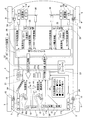
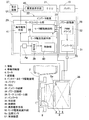
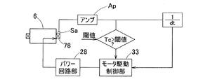
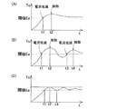
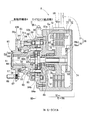
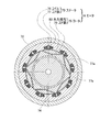
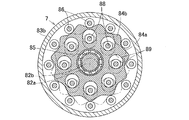
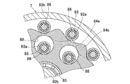
この発明の第1の実施形態に係る電気自動車を平面図で示す概念構成のブロック図である。1 is a block diagram of a conceptual configuration showing an electric vehicle according to a first embodiment of the present invention in a plan view. 同電気自動車のインバータ装置等の概念構成のブロック図である。It is a block diagram of conceptual composition, such as an inverter device of the electric vehicle. 同電気自動車の制御系のブロック図である。It is a block diagram of the control system of the electric vehicle. 同電気自動車のモータのモータコイルの温度と時間との関係を示す図である。It is a figure which shows the relationship between the temperature of the motor coil of the motor of the same electric vehicle, and time. 同電気自動車におけるインホイールモータ駆動装置の破断正面図である。It is a fracture front view of the in-wheel motor drive device in the electric vehicle. 図5のVI-VI 線断面となるモータ部分の断面図である。It is sectional drawing of the motor part used as the VI-VI line cross section of FIG. 図5のVII-VII線断面となる減速機部分の断面図である。It is sectional drawing of the reduction gear part used as the VII-VII line cross section of FIG. 図7の部分拡大断面図である。It is a partial expanded sectional view of FIG. この発明のさらに他の実施形態に係る電気自動車のECU等の概念構成のブロック図である。It is a block diagram of conceptual composition, such as ECU of an electric vehicle concerning other embodiments of this invention.

この発明の第1の実施形態に係る電気自動車を図1ないし図8と共に説明する。この電気自動車は、車体1の左右の後輪となる車輪2が駆動輪とされ、左右の前輪となる車輪3が従動輪の操舵輪とされた4輪の自動車である。駆動輪および従動輪となる車輪2,3は、いずれもタイヤを有し、それぞれ車輪用軸受4,5を介して車体1に支持されている。車輪用軸受4,5は、図1ではハブベアリングの略称「H/B」を付してある。駆動輪となる左右の車輪2,2は、それぞれ独立の走行用のモータ6,6により駆動される。モータ6の回転は、減速機7および車輪用軸受4を介して車輪2に伝達される。これらモータ6、減速機7、および車輪用軸受4は、互いに一つの組立部品であるインホイールモータ駆動装置8を構成しており、インホイールモータ駆動装置8は、一部または全体が車輪2内に配置される。インホイールモータ駆動装置8は、インホイールモータユニットとも称される。モータ6は、減速機7を介さずに直接に車輪2を回転駆動するものであっても良い。各車輪2,3には、電動式のブレーキ9,10が設けられている。   An electric vehicle according to a first embodiment of the present invention will be described with reference to FIGS. This electric vehicle is a four-wheeled vehicle in which the wheels 2 that are the left and right rear wheels of the vehicle body 1 are driving wheels, and the wheels 3 that are the left and right front wheels are steering wheels of driven wheels. Each of the wheels 2 and 3 serving as the driving wheel and the driven wheel has a tire and is supported by the vehicle body 1 via wheel bearings 4 and 5, respectively. The wheel bearings 4 and 5 are given the abbreviation “H / B” of the hub bearing in FIG. The left and right wheels 2, 2 serving as driving wheels are driven by independent traveling motors 6, 6, respectively. The rotation of the motor 6 is transmitted to the wheel 2 via the speed reducer 7 and the wheel bearing 4. The motor 6, the speed reducer 7, and the wheel bearing 4 constitute an in-wheel motor driving device 8 that is one assembly part, and the in-wheel motor driving device 8 is partially or entirely inside the wheel 2. Placed in. The in-wheel motor drive device 8 is also referred to as an in-wheel motor unit. The motor 6 may directly rotate and drive the wheels 2 without using the speed reducer 7. Each wheel 2, 3 is provided with an electric brake 9, 10.

左右の前輪となる操舵輪である車輪3,3は、転舵機構11を介して転舵可能であり、操舵機構12により操舵される。転舵機構11は、タイロッド11aを左右移動させることで、車輪用軸受5を保持した左右のナックルアーム11bの角度を変える機構であり、操舵機構12の指令によりEPS(電動パワーステアリング)モータ13を駆動させ、回転・直線運動変換機構(図示せず)を介して左右移動させられる。操舵角は操舵角センサ15で検出し、このセンサ出力はECU21に出力され、その情報は左右輪の加速・減速指令等に使用される。   The wheels 3 and 3 that are the steering wheels that are the left and right front wheels can be steered via the steering mechanism 11 and are steered by the steering mechanism 12. The steering mechanism 11 is a mechanism that changes the angle of the left and right knuckle arms 11b that hold the wheel bearings 5 by moving the tie rod 11a to the left and right. An EPS (electric power steering) motor 13 is driven by a command from the steering mechanism 12. It is driven and moved left and right via a rotation / linear motion conversion mechanism (not shown). The steering angle is detected by the steering angle sensor 15, and the sensor output is output to the ECU 21, and the information is used for acceleration / deceleration commands for the left and right wheels.

図5に示すように、インホイールモータ駆動装置8は、車輪用軸受4とモータ6との間に減速機7を介在させ、車輪用軸受4で支持される駆動輪である車輪2(図2)のハブとモータ6(図5)の回転出力軸74とを同軸心上で連結してある。減速機7は、減速比が1/6以上のものであるのが良い。この減速機7は、サイクロイド減速機であって、モータ6の回転出力軸74に同軸に連結される回転入力軸82に偏心部82a,82bを形成し、偏心部82a,82bにそれぞれ軸受85を介して曲線板84a,84bを装着し、曲線板84a,84bの偏心運動を車輪用軸受4へ回転運動として伝達する構成である。なお、この明細書において、車両に取り付けた状態で車両の車幅方向の外側寄りとなる側をアウトボード側と呼び、車両の中央寄りとなる側をインボード側と呼ぶ。   As shown in FIG. 5, the in-wheel motor drive device 8 has a reduction gear 7 interposed between the wheel bearing 4 and the motor 6, and the wheel 2 that is a drive wheel supported by the wheel bearing 4 (FIG. 2). ) And the rotation output shaft 74 of the motor 6 (FIG. 5) are connected coaxially. The reduction gear 7 should have a reduction ratio of 1/6 or more. The speed reducer 7 is a cycloid speed reducer, in which eccentric portions 82a and 82b are formed on a rotational input shaft 82 that is coaxially connected to a rotational output shaft 74 of the motor 6, and bearings 85 are provided on the eccentric portions 82a and 82b, respectively. The curvilinear plates 84a and 84b are attached to the discs, and the eccentric motion of the curvilinear plates 84a and 84b is transmitted to the wheel bearing 4 as rotational motion. In this specification, the side closer to the outer side in the vehicle width direction of the vehicle when attached to the vehicle is referred to as the outboard side, and the side closer to the center of the vehicle is referred to as the inboard side.

車輪用軸受4は、内周に複列の転走面53を形成した外方部材51と、これら各転走面53に対向する転走面54を外周に形成した内方部材52と、これら外方部材51および内方部材52の転走面53,54間に介在した複列の転動体55とで構成される。内方部材52は、駆動輪を取り付けるハブを兼用する。この車輪用軸受4は、複列のアンギュラ玉軸受とされていて、転動体55はボールからなり、各列毎に保持器56で保持されている。上記転走面53,54は断面円弧状であり、各転走面53,54は接触角が背面合わせとなるように形成されている。外方部材51と内方部材52との間の軸受空間のアウトボード側端は、シール部材57でシールされている。   The wheel bearing 4 includes an outer member 51 in which a double row rolling surface 53 is formed on the inner periphery, an inner member 52 in which a rolling surface 54 facing each of the rolling surfaces 53 is formed on the outer periphery, and these The outer member 51 and the inner member 52 are composed of double-row rolling elements 55 interposed between the rolling surfaces 53 and 54 of the inner member 52. The inner member 52 also serves as a hub for attaching the drive wheels. The wheel bearing 4 is a double-row angular ball bearing, and the rolling elements 55 are made of balls and are held by a cage 56 for each row. The rolling surfaces 53 and 54 have a circular arc cross section, and the rolling surfaces 53 and 54 are formed so that the contact angles are aligned with the back surface. An end on the outboard side of the bearing space between the outer member 51 and the inner member 52 is sealed with a seal member 57.

外方部材51は静止側軌道輪となるものであって、減速機7のアウトボード側のハウジング83bに取り付けるフランジ51aを有し、全体が一体の部品とされている。フランジ51aには、周方向の複数箇所にボルト挿通孔64が設けられている。また、ハウジング83bには,ボルト挿通孔64に対応する位置に、内周にねじが切られたボルト螺着孔94が設けられている。ボルト挿通孔94に挿通した取付ボルト65をボルト螺着孔94に螺着させることにより、外方部材51がハウジング83bに取り付けられる。   The outer member 51 is a stationary raceway, has a flange 51a attached to the housing 83b on the outboard side of the speed reducer 7, and is formed as an integral part. The flange 51a is provided with bolt insertion holes 64 at a plurality of locations in the circumferential direction. Further, the housing 83b is provided with a bolt screw hole 94 whose inner periphery is threaded at a position corresponding to the bolt insertion hole 64. The outer member 51 is attached to the housing 83b by screwing the mounting bolt 65 inserted into the bolt insertion hole 94 into the bolt screwing hole 94.

内方部材52は回転側軌道輪となるものであって、車輪取付用のハブフランジ59aを有するアウトボード側材59と、このアウトボード側材59の内周にアウトボード側が嵌合して加締めによってアウトボード側材59に一体化されたインボード側材60とでなる。これらアウトボード側材59およびインボード側材60に、前記各列の転走面54が形成されている。インボード側材60の中心には貫通孔61が設けられている。ハブフランジ59aには、周方向複数箇所にハブボルト66の圧入孔67が設けられている。アウトボード側材59のハブフランジ59aの根元部付近には、駆動輪および制動部品(図示せず)を案内する円筒状のパイロット部63がアウトボード側に突出している。このパイロット部63の内周には、前記貫通孔61のアウトボード側端を塞ぐキャップ68が取り付けられている。   The inner member 52 is a rotating raceway, and the outboard side member 59 having a hub flange 59a for wheel mounting and the outboard side member 59 are fitted to the inner periphery of the outboard side member 59. The inboard side material 60 is integrated with the outboard side material 59 by fastening. In each of the outboard side material 59 and the inboard side material 60, the rolling surface 54 of each row is formed. A through hole 61 is provided in the center of the inboard side member 60. The hub flange 59a is provided with press-fit holes 67 for hub bolts 66 at a plurality of locations in the circumferential direction. In the vicinity of the base portion of the hub flange 59a of the outboard side member 59, a cylindrical pilot portion 63 that guides driving wheels and braking components (not shown) protrudes toward the outboard side. A cap 68 that closes the outboard side end of the through hole 61 is attached to the inner periphery of the pilot portion 63.

モータ6は、円筒状のモータハウジング72に固定したモータステータ73と、回転出力軸74に取り付けたモータロータ75との間にラジアルギャップを設けたラジアルギャップ型のIPMモータ(すなわち埋込磁石型同期モータ)である。回転出力軸74は、減速機7のインボード側のハウジング83aの筒部に2つの軸受76で片持ち支持されている。   The motor 6 is a radial gap type IPM motor (that is, an embedded magnet type synchronous motor) in which a radial gap is provided between a motor stator 73 fixed to a cylindrical motor housing 72 and a motor rotor 75 attached to the rotation output shaft 74. ). The rotation output shaft 74 is cantilevered by two bearings 76 on the cylindrical portion of the housing 83 a on the inboard side of the speed reducer 7.

図6は、モータの断面図(図5のVI-VI 断面)を示す。モータ6のロータ75は、軟質磁性材料からなるコア部79と、このコア部79に内蔵される永久磁石80から構成される。永久磁石80は、隣り合う2つの永久磁石がロータコア部79内の同一円周上で断面ハ字状に向き合うように配列される。永久磁石80にはネオジウム系磁石が用いられている。ステータ73は軟質磁性材料からなるコア部77とコイル78で構成される。コア部77は外周面が断面円形とされたリング状で、その内周面に内径側に突出する複数のティース77aが円周方向に並んで形成されている。コイル78は、ステータコア部77の前記各ティース77aに巻回されている。   FIG. 6 is a cross-sectional view of the motor (cross-section VI-VI in FIG. 5). The rotor 75 of the motor 6 includes a core portion 79 made of a soft magnetic material and a permanent magnet 80 built in the core portion 79. The permanent magnets 80 are arranged so that two adjacent permanent magnets face each other in a cross-sectional shape on the same circumference in the rotor core portion 79. The permanent magnet 80 is a neodymium magnet. The stator 73 includes a core part 77 and a coil 78 made of a soft magnetic material. The core portion 77 has a ring shape with an outer peripheral surface having a circular cross section, and a plurality of teeth 77a protruding inward on the inner peripheral surface are formed side by side in the circumferential direction. The coil 78 is wound around the teeth 77 a of the stator core portion 77.

図5に示すように、モータ6には、モータステータ73とモータロータ75の間の相対回転角度を検出する角度センサ36が設けられる。角度センサ36は、モータステータ73とモータロータ75の間の相対回転角度を表す信号を検出して出力する角度センサ本体70と、この角度センサ本体70の出力する信号から角度を演算する角度演算回路71とを有する。角度センサ本体70は、回転出力軸74の外周面に設けられる被検出部70aと、モータハウジング72に設けられ前記被検出部70aに例えば径方向に対向して近接配置される検出部70bとでなる。被検出部70aと検出部70bは軸方向に対向して近接配置されるものであっても良い。角度センサ36はレゾルバであっても良い。このモータ6では、その効率を最大にするため、角度センサ36の検出するモータステータ73とモータロータ75の間の相対回転角度に基づき、モータステータ73のコイル78へ流す交流電流の各波の各相の印加タイミングを、モータコントール部29のモータ駆動制御部33によってコントロールするようにされている。
なお、インホイールモータ駆動装置8のモータ電流の配線や各種センサ系,指令系の配線は、モータハウジング72等に設けられたコネクタ99により纏めて行われる。
As shown in FIG. 5, the motor 6 is provided with an angle sensor 36 that detects a relative rotation angle between the motor stator 73 and the motor rotor 75. The angle sensor 36 detects and outputs a signal representing a relative rotation angle between the motor stator 73 and the motor rotor 75, and an angle calculation circuit 71 that calculates an angle from the signal output from the angle sensor body 70. And have. The angle sensor main body 70 includes a detected portion 70a provided on the outer peripheral surface of the rotation output shaft 74, and a detecting portion 70b provided in the motor housing 72 and disposed in close proximity to the detected portion 70a, for example, in the radial direction. Become. The detected portion 70a and the detecting portion 70b may be arranged close to each other in the axial direction. The angle sensor 36 may be a resolver. In this motor 6, in order to maximize the efficiency, each phase of each wave of alternating current flowing through the coil 78 of the motor stator 73 based on the relative rotation angle between the motor stator 73 and the motor rotor 75 detected by the angle sensor 36. Is controlled by the motor drive control unit 33 of the motor control unit 29.
Note that the motor current wiring of the in-wheel motor driving device 8 and various sensor system and command system wiring are collectively performed by a connector 99 provided in the motor housing 72 or the like.

減速機7は、上記したようにサイクロイド減速機であり、図7のように外形がなだらかな波状のトロコイド曲線で形成された2枚の曲線板84a,84bが、それぞれ軸受85を介して回転入力軸82の各偏心部82a,82bに装着してある。これら各曲線板84a,84bの偏心運動を外周側で案内する複数の外ピン86を、それぞれハウジング83bに差し渡して設け、内方部材2のインボード側材60に取り付けた複数の内ピン88を、各曲線板84a,84bの内部に設けられた複数の円形の貫通孔89に挿入状態に係合させてある。回転入力軸82は、モータ6の回転出力軸74とスプライン結合されて一体に回転する。なお、回転入力軸82はインボード側のハウジング83aと内方部材52のインボード側材60の内径面とに2つの軸受90で両持ち支持されている。   The speed reducer 7 is a cycloid speed reducer as described above, and the two curved plates 84a and 84b formed by the wavy trochoid curve having a gentle outer shape as shown in FIG. The shaft 82 is attached to each eccentric part 82a, 82b. A plurality of outer pins 86 for guiding the eccentric movements of the curved plates 84a and 84b on the outer peripheral side are provided across the housing 83b, and a plurality of inner pins 88 attached to the inboard side member 60 of the inner member 2 are provided. The curved plates 84a and 84b are engaged with a plurality of circular through holes 89 provided in the inserted state. The rotation input shaft 82 is spline-coupled with the rotation output shaft 74 of the motor 6 and rotates integrally. The rotary input shaft 82 is supported at both ends by two bearings 90 on the inboard side housing 83a and the inner diameter surface of the inboard side member 60 of the inner member 52.

モータ6の回転出力軸74が回転すると、これと一体回転する回転入力軸82に取り付けられた各曲線板84a,84bが偏心運動を行う。この各曲線板84a,84bの偏心運動が、内ピン88と貫通孔89との係合によって、内方部材52に回転運動として伝達される。回転出力軸74の回転に対して内方部材52の回転は減速されたものとなる。例えば、1段のサイクロイド減速機で1/10以上の減速比を得ることができる。   When the rotation output shaft 74 of the motor 6 rotates, the curved plates 84a and 84b attached to the rotation input shaft 82 that rotates integrally therewith perform an eccentric motion. The eccentric motions of the curved plates 84 a and 84 b are transmitted to the inner member 52 as rotational motion by the engagement of the inner pins 88 and the through holes 89. The rotation of the inner member 52 is decelerated with respect to the rotation of the rotation output shaft 74. For example, a reduction ratio of 1/10 or more can be obtained with a single-stage cycloid reducer.

前記2枚の曲線板84a,84bは、互いに偏心運動が打ち消されるように180°位相をずらして回転入力軸82の各偏心部82a,82bに装着され、各偏心部82a,82bの両側には、各曲線板84a,84bの偏心運動による振動を打ち消すように、各偏心部82a,82bの偏心方向と逆方向へ偏心させたカウンターウエイト91が装着されている。   The two curved plates 84a and 84b are attached to the eccentric portions 82a and 82b of the rotary input shaft 82 so as to cancel out the eccentric motion with each other, and are mounted on both sides of the eccentric portions 82a and 82b. A counterweight 91 that is eccentric in the direction opposite to the eccentric direction of the eccentric portions 82a and 82b is mounted so as to cancel the vibration caused by the eccentric movement of the curved plates 84a and 84b.

図8に拡大して示すように、前記各外ピン86と内ピン88には軸受92,93が装着され、これらの軸受92,93の外輪92a,93aが、それぞれ各曲線板84a,84bの外周と各貫通孔89の内周とに転接するようになっている。したがって、外ピン86と各曲線板84a,84bの外周との接触抵抗、および内ピン88と各貫通孔89の内周との接触抵抗を低減し、各曲線板84a,84bの偏心運動をスムーズに内方部材52に回転運動として伝達することができる。   As shown in an enlarged view in FIG. 8, bearings 92 and 93 are mounted on the outer pins 86 and the inner pins 88, and outer rings 92a and 93a of the bearings 92 and 93 are respectively connected to the curved plates 84a and 84b. It comes into rolling contact with the outer periphery and the inner periphery of each through-hole 89. Therefore, the contact resistance between the outer pin 86 and the outer periphery of each curved plate 84a, 84b and the contact resistance between the inner pin 88 and the inner periphery of each through hole 89 are reduced, and the eccentric motion of each curved plate 84a, 84b is smooth. Can be transmitted to the inner member 52 as a rotational motion.

図5において、このインホイールモータ駆動装置8の車輪用軸受4は、減速機7のハウジング83bまたはモータ6のハウジング72の外周部で、ナックル等の懸架装置(図示せず)を介して車体に固定される。   In FIG. 5, the wheel bearing 4 of the in-wheel motor drive device 8 is attached to the vehicle body via a suspension device (not shown) such as a knuckle on the outer periphery of the housing 83b of the speed reducer 7 or the housing 72 of the motor 6. Fixed.

制御系を説明する。図1に示すように、制御装置U1は、自動車全般の制御を行う電気制御ユニットであるECU21と、このECU21の指令に従って走行用のモータ6の制御を行うインバータ装置22とを有する。前記ECU21と、インバータ装置22と、ブレーキコントローラ23とが、車体1に搭載されている。ECU21は、コンピュータとこれに実行されるプログラム、並びに各種の電子回路等で構成される。   The control system will be described. As shown in FIG. 1, the control device U <b> 1 includes an ECU 21 that is an electric control unit that controls the entire automobile, and an inverter device 22 that controls the traveling motor 6 in accordance with a command from the ECU 21. The ECU 21, the inverter device 22, and the brake controller 23 are mounted on the vehicle body 1. The ECU 21 includes a computer, a program executed by the computer, various electronic circuits, and the like.

ECU21は、機能別に大別すると駆動制御部21aと一般制御部21bとに分けられる。駆動制御部21aは、アクセル操作部16の出力する加速指令と、ブレーキ操作部17の出力する減速指令と、操舵角センサ15の出力する旋回指令とから、左右輪の走行用モータ6,6に与える加速・減速指令を生成し、インバータ装置22へ出力する。駆動制御部21aは、上記の他に、出力する加速・減速指令を、各車輪2,3の車輪用軸受4,5に設けられた回転センサ24から得られるタイヤ回転数の情報や、車載の各センサの情報を用いて補正する機能を有していても良い。アクセル操作部16は、アクセルペダルとその踏み込み量を検出して前記加速指令を出力するセンサ16aとでなる。ブレーキ操作部17は、ブレーキペダルとその踏み込み量を検出して前記減速指令を出力するセンサ17aとでなる。   The ECU 21 is roughly divided into a drive control unit 21a and a general control unit 21b when classified roughly by function. The drive control unit 21a gives the left and right wheel motors 6 and 6 the acceleration command output from the accelerator operation unit 16, the deceleration command output from the brake operation unit 17, and the turning command output from the steering angle sensor 15. The given acceleration / deceleration command is generated and output to the inverter device 22. In addition to the above, the drive control unit 21a outputs an acceleration / deceleration command to be output, information on the tire rotation speed obtained from the rotation sensor 24 provided on the wheel bearings 4 and 5 of the wheels 2 and 3, You may have the function to correct | amend using the information of each sensor. The accelerator operation unit 16 includes an accelerator pedal and a sensor 16a that detects the amount of depression and outputs the acceleration command. The brake operation unit 17 includes a brake pedal and a sensor 17a that detects the amount of depression and outputs the deceleration command.

ECU21の一般制御部21bは、前記ブレーキ操作部17の出力する減速指令をブレーキコントローラ23へ出力する機能、各種の補機システム25を制御する機能、コンソールの操作パネル26からの入力指令を処理する機能、表示手段27に表示を行う機能などを有する。前記補機システム25は、例えば、エアコン、ライト、ワイパー、GPS、アエバッグ等であり、ここでは代表して一つのブロックとして示す。   The general control unit 21b of the ECU 21 processes a function of outputting a deceleration command output from the brake operation unit 17 to the brake controller 23, a function of controlling various auxiliary machine systems 25, and an input command from the console operation panel 26. A function, a function of displaying on the display means 27, and the like. The auxiliary machine system 25 is, for example, an air conditioner, a light, a wiper, a GPS, an air bag, and the like, and is shown here as a representative block.

ブレーキコントローラ23は、ECU21から出力される減速指令に従って、各車輪2,3のブレーキ9,10に制動指令を与える手段である。ECU21から出力される制動指令には、ブレーキ操作部17の出力する減速指令によって生成される指令の他に、ECU21の持つ安全性向上のための手段によって生成される指令がある。ブレーキコントローラ23は、この他にアンチロックブレーキシステムを備える。ブレーキコントローラ23は、電子回路やマイコン等により構成される。   The brake controller 23 is means for giving a braking command to the brakes 9 and 10 of the wheels 2 and 3 in accordance with a deceleration command output from the ECU 21. In addition to the command generated by the deceleration command output from the brake operation unit 17, the braking command output from the ECU 21 includes a command generated by means for improving the safety of the ECU 21. In addition, the brake controller 23 includes an antilock brake system. The brake controller 23 is configured by an electronic circuit, a microcomputer, or the like.

インバータ装置22は、各モータ6に対して設けられたパワー回路部28と、このパワー回路部28を制御するモータコントール部29とで構成される。モータコントール部29は、各パワー回路部28に対して共通して設けられていても、別々に設けられていても良いが、共通して設けられた場合であっても、各パワー回路部28を、例えば互いにモータトルクが異なるように独立して制御可能なものとされる。モータコントール部29は、このモータコントール部29が持つインホイールモータ8に関する各検出値や制御値等の各情報(「IWMシステム情報」と称す)をECUに出力する機能を有する。   The inverter device 22 includes a power circuit unit 28 provided for each motor 6 and a motor control unit 29 that controls the power circuit unit 28. The motor control unit 29 may be provided in common for each power circuit unit 28 or may be provided separately, but even if it is provided in common, each power circuit unit 28. For example, can be controlled independently so that the motor torque is different from each other. The motor control unit 29 has a function of outputting information (referred to as “IWM system information”) such as detection values and control values related to the in-wheel motor 8 of the motor control unit 29 to the ECU.

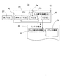
図2は、インバータ装置22等の概念構成を示すブロック図である。パワー回路部28は、バッテリ19の直流電力をモータ6の駆動に用いる3相の交流電力に変換するインバータ31と、このインバータ31を制御するPWMドライバ32とで構成される。モータ6は3相の同期モータ等からなる。インバータ31は、複数の半導体スイッチング素子(図示せず)で構成され、PWMドライバ32は、入力された電流指令をパルス幅変調し、前記各半導体スイッチング素子にオンオフ指令を与える。   FIG. 2 is a block diagram showing a conceptual configuration of the inverter device 22 and the like. The power circuit unit 28 includes an inverter 31 that converts the DC power of the battery 19 into three-phase AC power that is used to drive the motor 6, and a PWM driver 32 that controls the inverter 31. The motor 6 is composed of a three-phase synchronous motor or the like. The inverter 31 is composed of a plurality of semiconductor switching elements (not shown), and the PWM driver 32 performs pulse width modulation on the input current command and gives an on / off command to each of the semiconductor switching elements.

モータコントール部29は、コンピュータとこれに実行されるプログラム、および電子回路により構成され、その基本となる制御部としてモータ駆動制御部33を有している。モータ駆動制御部33は、上位制御手段であるECUから与えられるトルク指令等による加速・減速指令に従い、電流指令に変換して、パワー回路部28のPWMドライバ32に電流指令を与える手段である。モータ駆動制御部33は、インバータ31からモータ6に流すモータ電流値を電流検出手段35から得て、電流フィードバック制御を行う。また、モータ駆動制御部33は、モータ6のロータの回転角を角度センサ36から得て、ベクトル制御を行う。   The motor control unit 29 includes a computer, a program executed on the computer, and an electronic circuit, and includes a motor drive control unit 33 as a basic control unit. The motor drive control unit 33 is a unit that converts the current command into a current command in accordance with an acceleration / deceleration command by a torque command or the like given from the ECU that is the host control unit, and gives the current command to the PWM driver 32 of the power circuit unit 28. The motor drive control unit 33 obtains a motor current value to be passed from the inverter 31 to the motor 6 from the current detection unit 35 and performs current feedback control. The motor drive control unit 33 obtains the rotation angle of the rotor of the motor 6 from the angle sensor 36 and performs vector control.

この実施形態では、上記構成のモータコントール部29に、次のモータ電流低減手段95、および異常報告手段41を設け、ECU21に異常表示手段42を設けている。また、モータ6に、このモータコイル78(図5)の温度Tcを検出する温度センサSaを設けている。
モータ電流低減手段95は、モータ6の電流値を低減するものである。このモータ電流低減手段95は、前記温度センサSaで検出されるモータコイル78の温度Tcが、定められた閾値を超えたとき、この温度Tcを時間tで微分したdTc/dtが0以下になるまでモータ6の電流値を低減する。具体的には、モータ電流低減手段95は、判定部39と、制御部40とを有する。
In this embodiment, the motor control unit 29 having the above configuration is provided with the following motor current reduction means 95 and the abnormality report means 41, and the ECU 21 is provided with the abnormality display means 42. The motor 6 is provided with a temperature sensor Sa for detecting the temperature Tc of the motor coil 78 (FIG. 5).
The motor current reducing means 95 is for reducing the current value of the motor 6. When the temperature Tc of the motor coil 78 detected by the temperature sensor Sa exceeds a predetermined threshold value, the motor current reducing means 95 has dTc / dt obtained by differentiating the temperature Tc with respect to time t to 0 or less. Until the current value of the motor 6 is reduced. Specifically, the motor current reducing unit 95 includes a determination unit 39 and a control unit 40.

前記温度センサSaとして例えばサーミスタが使用される。このサーミスタを、モータコイル78に接触固定することで、モータコイル78の温度Tcを検出し得る。この例では、図2および図3に示すように、サーミスタで検出された検出値はアンプApで増幅され、この増幅値が判定部39にて判定される。
判定部39は、温度センサSaで検出される温度Tcが定められた閾値を超えるか否かを常時判定する。前記閾値は、例えば、実験、シミュレーション等により、モータコイルに絶縁を生じさせる、モータコイル78の温度および時間の関係に基づいて適宜に求められる。モータコイル78に絶縁が生じたか否かは、モータ6に印加するモータ印加電圧に対するモータ電流値を、絶縁が生じていない基準値と比較することで判断し得る。なおモータ印加電圧は、電流検出手段35の後段等に設けられる図示外の電圧センサにより得られ、モータ電流値は、電流検出手段35により得られる。求められた閾値は、テーブルとして図示外の記憶手段に書換え可能に記憶されている。
For example, a thermistor is used as the temperature sensor Sa. By fixing the thermistor in contact with the motor coil 78, the temperature Tc of the motor coil 78 can be detected. In this example, as shown in FIGS. 2 and 3, the detection value detected by the thermistor is amplified by the amplifier Ap, and this amplification value is determined by the determination unit 39.
The determination unit 39 always determines whether or not the temperature Tc detected by the temperature sensor Sa exceeds a predetermined threshold value. The threshold is appropriately determined based on the relationship between the temperature and time of the motor coil 78 that causes insulation in the motor coil, for example, through experiments and simulations. Whether or not insulation has occurred in the motor coil 78 can be determined by comparing the motor current value with respect to the motor applied voltage applied to the motor 6 with a reference value in which insulation has not occurred. The motor applied voltage is obtained by a voltage sensor (not shown) provided at a subsequent stage or the like of the current detection means 35, and the motor current value is obtained by the current detection means 35. The obtained threshold values are stored as a table in a rewritable storage means (not shown).

制御部40は、検出されるモータコイル78の温度Tcが、定められた閾値を超えたと判定したときに、モータ6の電流値を低減するように、モータ駆動制御部33を介してパワー回路部28に指令する。モータ電流の低減は、現在の電流に対して定められた割合(例えば、90%)で低下させても良いし、また定められた値低下させても良い。その後、温度Tcが変化する度合いが一定または低下になる兆候が認識されたとき、つまり温度上昇率であるdTc/dtが0以下になると、実際の温度Tcが下がるのを待つことなく、モータ電流を低減する制御を解除する。このため、モータ6の急激な駆動制限が防止される。dTc/dtが0以下になるとは、任意の微小時間における温度Tcの傾きが0以下になることと同義である。モータコイル78の温度は、急には下がらず、温度がある程度下がるまでモータ電流を低減すると、モータ6の急激な駆動制限によって車両の運転が妨げられることがあるが、上記のように温度低下の兆候をとらえて電流制限を解除することで、モータ6の急減な駆動制限による問題が回避される。   When it is determined that the detected temperature Tc of the motor coil 78 exceeds a predetermined threshold, the control unit 40 is configured to reduce the current value of the motor 6 via the motor drive control unit 33 so as to reduce the current value of the motor 6. Command to 28. The motor current may be reduced at a predetermined rate (for example, 90%) with respect to the current current, or may be reduced by a predetermined value. Thereafter, when an indication that the degree of change in temperature Tc is constant or reduced is recognized, that is, when dTc / dt, which is the rate of temperature increase, becomes 0 or less, the motor current is not waited for the actual temperature Tc to decrease. Release the control to reduce. For this reason, sudden drive restriction of the motor 6 is prevented. The dTc / dt being 0 or less is synonymous with the fact that the gradient of the temperature Tc in an arbitrary minute time is 0 or less. The temperature of the motor coil 78 does not drop suddenly, and if the motor current is reduced until the temperature drops to some extent, the driving of the vehicle may be hindered due to the sudden drive restriction of the motor 6, but the temperature drop as described above. By detecting the signs and releasing the current limit, problems due to the sudden drive limit of the motor 6 can be avoided.

モータ電流低減手段95の制御解除によって、モータコイル78の温度Tcが上がり始めても、そのときは、温度Tcが閾値以上の温度であれば、再度モータ6の電流値を低減する制御を行う。そのため、温度上昇率が0以下になったときに、モータ電流を低減する制御を解除しても過負荷の確実な防止が行える。具体的に、図4(A)〜(C)は、それぞれこの電気自動車のモータ6のモータコイル78の温度Tcと時間tとの関係を示す図である。
図4(A)では、モータコイル78の温度Tcが上昇し時間t1のとき、判定部39は、モータコイル78の温度Tcが閾値Eaを超えたと判定する。制御部40は、この判定結果を受けて、モータ6の電流値を低減するように、モータ駆動制御部33を介してパワー回路部28に指令する。モータ駆動制御部33は、制御部40から与えられる指令に従い、パワー回路部28のPWMドライバ32に電流指令を与える。パワー回路部28は、モータ6へ供給する電流を低減させる。
Even if the temperature Tc of the motor coil 78 starts to increase due to the cancellation of the control of the motor current reducing means 95, at this time, if the temperature Tc is equal to or higher than the threshold value, control is performed to reduce the current value of the motor 6 again. Therefore, when the rate of temperature increase becomes 0 or less, overload can be reliably prevented even if the control for reducing the motor current is canceled. Specifically, FIGS. 4A to 4C are diagrams showing the relationship between the temperature Tc of the motor coil 78 of the motor 6 of this electric vehicle and the time t, respectively.
In FIG. 4A, when the temperature Tc of the motor coil 78 rises and time t1, the determination unit 39 determines that the temperature Tc of the motor coil 78 has exceeded the threshold value Ea. The control unit 40 receives the determination result and instructs the power circuit unit 28 via the motor drive control unit 33 to reduce the current value of the motor 6. The motor drive control unit 33 gives a current command to the PWM driver 32 of the power circuit unit 28 in accordance with a command given from the control unit 40. The power circuit unit 28 reduces the current supplied to the motor 6.

時間t2において温度上昇率dTc/dtが「0」(温度Tcが一定)となることで、制御部40は、モータ6の電流値を低減させる制御を解除する。この図4(A)の例では、時間t2以後dTc/dtがマイナス(温度Tcが低下)となるため、モータ温度Tcが閾値Ea以上であっても、実際の温度Tcが下がるのを待つことなく制御部40は、モータ電流を低減する制御の解除を続行する。   When the temperature increase rate dTc / dt becomes “0” (temperature Tc is constant) at time t <b> 2, the control unit 40 releases the control for reducing the current value of the motor 6. In the example of FIG. 4A, since dTc / dt becomes negative (temperature Tc decreases) after time t2, even if the motor temperature Tc is equal to or higher than the threshold value Ea, it waits for the actual temperature Tc to decrease. Instead, the control unit 40 continues to cancel the control to reduce the motor current.

図4(B)においても、時間t1のとき、制御部40は、判定部39による判定結果を受けて、モータ6の電流値を低減するように、モータ駆動制御部33を介してパワー回路部28に指令する。時間t2以後、モータ電流低減手段95の制御解除によって、モータコイル78の温度Tcが上がり始めても、時間t3で温度Tcが閾値以上の温度であると判定されることで、制御部40は、再度モータ6の電流値を低減する制御を行う。そのため、温度上昇率が0以下になると、モータ電流を低減する制御を解除しても過負荷の確実な防止が行える。   Also in FIG. 4B, at time t1, the control unit 40 receives the determination result by the determination unit 39 and reduces the current value of the motor 6 via the motor drive control unit 33. Command to 28. After the time t2, even if the temperature Tc of the motor coil 78 starts to rise due to the cancellation of the control of the motor current reduction means 95, the controller 40 determines again that the temperature Tc is equal to or higher than the threshold at time t3. Control to reduce the current value of the motor 6 is performed. Therefore, when the rate of temperature increase is 0 or less, overload can be reliably prevented even if the control for reducing the motor current is canceled.

図2に示すように、異常報告手段41は、判定部39により温度Tcが閾値を超えたと判定したときに、ECU21に異常発生情報を出力する手段である。
ECU21に設けられた異常表示手段42は、異常報告手段41から出力されたモータ6の異常発生情報を受けて、運転席の表示装置27に、異常を知らせる表示を行わせる手段である。表示装置27における表示は、文字や記号による表示、例えばアイコンによる表示とされる。
As shown in FIG. 2, the abnormality reporting unit 41 is a unit that outputs abnormality occurrence information to the ECU 21 when the determination unit 39 determines that the temperature Tc has exceeded a threshold value.
The abnormality display unit 42 provided in the ECU 21 is a unit that receives the abnormality occurrence information of the motor 6 output from the abnormality report unit 41 and causes the display device 27 in the driver's seat to perform a display notifying the abnormality. The display on the display device 27 is a display using characters or symbols, for example, an icon.

作用効果について説明する。
この構成によると、温度センサSaは、モータコイル78の温度Tcを常時検出する。例えば、坂道等において連続して高トルク発生状態で電気自動車を運転した場合、モータコイル78の温度Tcが上昇する。判定部39は、検出される温度Tcが定められた閾値を超えるか否かを判定し、超えたと判定したときに制御部40は、モータ6の電流値を低減するようにパワー回路部28に指令する。その後、温度Tcが下がる度合いが一定になる傾向が認識されたとき、つまり温度上昇率であるdTc/dtが0以下になると、実際の温度Tcが下がるのを待つことなく、モータ電流を低減する制御を解除するので、モータ6の急激な駆動制限が防止される。
モータ電流低減手段95の制御解除によって、モータコイル78の温度Tcが上がり始めても、そのときは、温度Tcが閾値以上の温度であれば、再度モータ6の電流値を低減する制御を行う。そのため、温度上昇率が0以下になると、モータ電流を低減する制御を解除しても過負荷の確実な防止が行える。
The effect will be described.
According to this configuration, the temperature sensor Sa always detects the temperature Tc of the motor coil 78. For example, when the electric vehicle is operated in a state where high torque is generated continuously on a slope or the like, the temperature Tc of the motor coil 78 increases. The determination unit 39 determines whether or not the detected temperature Tc exceeds a predetermined threshold value, and when it is determined that the detected temperature Tc has exceeded, the control unit 40 causes the power circuit unit 28 to reduce the current value of the motor 6. Command. After that, when the tendency of the temperature Tc to decrease becomes constant, that is, when the temperature increase rate dTc / dt becomes 0 or less, the motor current is reduced without waiting for the actual temperature Tc to decrease. Since the control is released, sudden drive restriction of the motor 6 is prevented.
Even if the temperature Tc of the motor coil 78 starts to increase due to the cancellation of the control of the motor current reducing means 95, at this time, if the temperature Tc is equal to or higher than the threshold value, control is performed to reduce the current value of the motor 6 again. Therefore, when the rate of temperature increase is 0 or less, overload can be reliably prevented even if the control for reducing the motor current is canceled.

モータ電流低減手段95を、インバータ装置22のモータコントロール部29に設け、モータ6に近い部位で検出温度の判定等を行えるため、配線上有利であり、ECU21に設ける場合に比べて迅速な制御が行え、車両走行上の問題を迅速に回避することができる。また高機能化により煩雑化が進むECU21の負担を軽減することができる。
ECU21は、車両全般を統括して制御する装置であるため、インバータ装置22におけるモータ電流低減手段95により、モータコイル78の異常を検出したとき、ECU21にモータ6の異常報告を出力することで、ECU21により車両全体の適切な制御が行える。また、ECU21はインバータ装置22に駆動の指令を与える上位制御手段であり、インバータ装置22による応急的な制御の後、ECU21により、その後の駆動のより適切な制御を行うことも可能となる。
Since the motor current reducing means 95 is provided in the motor control unit 29 of the inverter device 22 so that the detected temperature can be determined at a location close to the motor 6, it is advantageous in terms of wiring, and quicker control than in the case where it is provided in the ECU 21. It is possible to quickly avoid problems in running the vehicle. Further, it is possible to reduce the burden on the ECU 21 that is becoming more complicated due to higher functions.
Since the ECU 21 is a device that controls the vehicle in general, when the motor current reduction means 95 in the inverter device 22 detects an abnormality in the motor coil 78, the ECU 21 outputs an abnormality report of the motor 6 to the ECU 21. The ECU 21 can appropriately control the entire vehicle. The ECU 21 is a higher-level control unit that gives a drive command to the inverter device 22. After the emergency control by the inverter device 22, the ECU 21 can perform more appropriate control of the subsequent drive.

また、インホイールモータ駆動装置8の場合、コンパクト化を図る結果、車輪用軸受4、減速機7、およびモータ6は、材料使用量の削減、モータ6の高速回転化を伴うため、これらの信頼性確保が重要な課題となる。特に、モータコイル78の温度を検出し、モータコイル78の異常、例えば絶縁劣化等を常時監視することで、モータ6の電流値を適切に低減する制御を行うことができる。   In addition, in the case of the in-wheel motor drive device 8, as a result of downsizing, the wheel bearing 4, the speed reducer 7, and the motor 6 are accompanied by a reduction in the amount of material used and a high-speed rotation of the motor 6. Ensuring safety is an important issue. In particular, the current of the motor 6 can be controlled appropriately by detecting the temperature of the motor coil 78 and constantly monitoring abnormalities of the motor coil 78, such as insulation deterioration.

インホイールモータ駆動装置8における減速機7をサイクロイド減速機として減速比を例えば1/6以上に高くした場合、モータ6の小型化を図り、装置のコンパクト化を図ることができる。減速比を高くした場合、モータ6は高速回転するものが用いられる。モータ6が高速回転状態のとき、モータ6のモータコイル78の絶縁劣化等の異常を早期に検知し、適切な対処が迅速に行える。   When the reduction gear 7 in the in-wheel motor drive device 8 is a cycloid reduction gear and the reduction ratio is increased to, for example, 1/6 or more, the motor 6 can be downsized and the device can be downsized. When the reduction ratio is increased, the motor 6 that rotates at high speed is used. When the motor 6 is in a high-speed rotation state, abnormalities such as insulation deterioration of the motor coil 78 of the motor 6 can be detected at an early stage, and appropriate measures can be quickly taken.

モータ6の電流を低減させる際、モータ電流を低減させる定められた割合は、例えば、経過時間毎にモータ電流値の全体の数%ずつ低減させるようにしても良いし、経過時間毎にモータ電流値を低減させる割合を暫時増やすようにしても良い。
図9に示すように、モータ電流低減手段95を、車両全般を制御する電気制御ユニットであるECU21に設けても良い。
When the current of the motor 6 is reduced, the predetermined ratio for reducing the motor current may be reduced by, for example, several percent of the total motor current value for each elapsed time, or the motor current for each elapsed time. You may make it increase the ratio which reduces a value for a while.
As shown in FIG. 9, the motor current reducing means 95 may be provided in the ECU 21 that is an electric control unit that controls the entire vehicle.

2…車輪
4…車輪用軸受
6…モータ
7…減速機
8…インホイールモータ駆動装置
19…バッテリ
21…ECU
22…インバータ装置
28…パワー回路部
29…モータコントール部
31…インバータ
39…判定部
40…制御部
41…異常報告手段
78…モータコイル
95…モータ電流低減手段
Sa…温度センサ
U1…制御装置
DESCRIPTION OF SYMBOLS 2 ... Wheel 4 ... Wheel bearing 6 ... Motor 7 ... Reduction gear 8 ... In-wheel motor drive device 19 ... Battery 21 ... ECU
DESCRIPTION OF SYMBOLS 22 ... Inverter apparatus 28 ... Power circuit part 29 ... Motor control part 31 ... Inverter 39 ... Determination part 40 ... Control part 41 ... Abnormality report means 78 ... Motor coil 95 ... Motor current reduction means Sa ... Temperature sensor U1 ... Control apparatus

Claims (6)

車輪を駆動するモータと、このモータを制御する制御装置とを備えた電気自動車において、
前記モータのモータコイルに、このモータコイルの温度Tcを検出する温度センサを設け、この温度センサで検出される温度Tcが閾値を超えたとき、この温度Tcを時間tで微分したdTc/dtが0以下になるまでモータの電流値を低減するモータ電流低減手段を設けたことを特徴とする電気自動車。
In an electric vehicle equipped with a motor for driving wheels and a control device for controlling the motor,
The motor coil of the motor is provided with a temperature sensor for detecting the temperature Tc of the motor coil. When the temperature Tc detected by the temperature sensor exceeds a threshold value, dTc / dt obtained by differentiating the temperature Tc with respect to time t is An electric vehicle comprising motor current reduction means for reducing the current value of the motor until it becomes 0 or less.
請求項1において、前記制御装置は、車両全般を制御する電気制御ユニットであるECUと、バッテリの直流電力を前記モータの駆動に用いる交流電力に変換するインバータを含むパワー回路部および前記ECUの制御に従って少なくとも前記パワー回路部を制御するモータコントロール部を有するインバータ装置とを有する電気自動車。   2. The control device according to claim 1, wherein the control device includes an ECU that is an electric control unit that controls the entire vehicle, a power circuit unit that includes an inverter that converts DC power of the battery into AC power used to drive the motor, and control of the ECU. And an inverter device having a motor control unit for controlling at least the power circuit unit. 請求項2において、前記モータコントロール部にモータ電流低減手段を設け、このモータ電流低減手段は、温度センサで検出される温度が閾値を超えるか否かを判定する判定部と、検出される温度が前記閾値を超えたと判定したときに、モータの電流値を低減するようにパワー回路部に指令する制御部とを有する電気自動車。   The motor control unit according to claim 2, wherein the motor control unit is provided with a motor current reduction unit. The motor current reduction unit includes a determination unit that determines whether or not the temperature detected by the temperature sensor exceeds a threshold value, and the detected temperature is An electric vehicle comprising: a control unit that commands the power circuit unit to reduce the current value of the motor when it is determined that the threshold value has been exceeded. 請求項3において、前記検出される温度が前記閾値を超えたと判定部で判定されたとき、前記ECUにモータの異常報告を出力する異常報告手段を前記インバータ装置に設けた電気自動車。   The electric vehicle according to claim 3, wherein when the determination unit determines that the detected temperature exceeds the threshold value, the inverter device includes an abnormality report unit that outputs a motor abnormality report to the ECU. 請求項1ないし請求項4のいずれか1項において、前記モータは、一部または全体が車輪内に配置されて前記モータと車輪用軸受と減速機とを含むインホイールモータ駆動装置を構成する電気自動車。   5. The electric motor according to claim 1, wherein the motor is partly or wholly disposed in a wheel and constitutes an in-wheel motor drive device including the motor, a wheel bearing, and a speed reducer. Car. 請求項1ないし請求項5のいずれか1項において、前記モータの回転を減速する減速機を備え、前記減速機はサイクロイド減速機である電気自動車。   The electric vehicle according to any one of claims 1 to 5, further comprising a speed reducer that decelerates rotation of the motor, wherein the speed reducer is a cycloid speed reducer.
JP2011039854A 2011-02-25 2011-02-25 Electric car Expired - Fee Related JP5731233B2 (en)

Priority Applications (7)

Application Number Priority Date Filing Date Title
JP2011039854A JP5731233B2 (en) 2011-02-25 2011-02-25 Electric car
CN201510564407.1A CN105150853B (en) 2011-02-25 2012-02-10 Electric automobile
EP12749174.4A EP2680434B1 (en) 2011-02-25 2012-02-10 Electric automobile
CN201280010175.XA CN103415992B (en) 2011-02-25 2012-02-10 Electric automobile
US14/000,295 US8950528B2 (en) 2011-02-25 2012-02-10 Electric automobile
PCT/JP2012/053061 WO2012114902A1 (en) 2011-02-25 2012-02-10 Electric automobile
US14/587,240 US9751409B2 (en) 2011-02-25 2014-12-31 Electric automobile

Applications Claiming Priority (1)

Application Number Priority Date Filing Date Title
JP2011039854A JP5731233B2 (en) 2011-02-25 2011-02-25 Electric car

Related Child Applications (1)

Application Number Title Priority Date Filing Date
JP2013160038A Division JP5731593B2 (en) 2013-08-01 2013-08-01 Electric car

Publications (2)

Publication Number Publication Date
JP2012178917A true JP2012178917A (en) 2012-09-13
JP5731233B2 JP5731233B2 (en) 2015-06-10

Family

ID=46980395

Family Applications (1)

Application Number Title Priority Date Filing Date
JP2011039854A Expired - Fee Related JP5731233B2 (en) 2011-02-25 2011-02-25 Electric car

Country Status (1)

Country Link
JP (1) JP5731233B2 (en)

Cited By (7)

* Cited by examiner, † Cited by third party
Publication number Priority date Publication date Assignee Title
JP2013252051A (en) * 2013-08-01 2013-12-12 Ntn Corp Electric vehicle
US8862302B1 (en) * 2013-06-04 2014-10-14 Ford Global Technologies, Llc Vehicle and method for controlling an electric machine
WO2015045903A1 (en) 2013-09-26 2015-04-02 Ntn株式会社 Wheel drive device
WO2015115217A1 (en) 2014-01-28 2015-08-06 Ntn株式会社 In-wheel motor drive device
US9751409B2 (en) 2011-02-25 2017-09-05 Ntn Corporation Electric automobile
JP2018046742A (en) * 2017-10-19 2018-03-22 Ntn株式会社 In-wheel motor drive device
WO2019064617A1 (en) * 2017-09-29 2019-04-04 三菱電機株式会社 Home electric appliance

Citations (4)

* Cited by examiner, † Cited by third party
Publication number Priority date Publication date Assignee Title
JPH11341884A (en) * 1998-05-27 1999-12-10 Kansai Electric Power Co Inc:The Inverter device
JP2003304604A (en) * 2002-04-09 2003-10-24 Nissan Motor Co Ltd Motor control device and method
JP2008168790A (en) * 2007-01-12 2008-07-24 Ntn Corp In-wheel motor drive
JP2013252051A (en) * 2013-08-01 2013-12-12 Ntn Corp Electric vehicle

Patent Citations (4)

* Cited by examiner, † Cited by third party
Publication number Priority date Publication date Assignee Title
JPH11341884A (en) * 1998-05-27 1999-12-10 Kansai Electric Power Co Inc:The Inverter device
JP2003304604A (en) * 2002-04-09 2003-10-24 Nissan Motor Co Ltd Motor control device and method
JP2008168790A (en) * 2007-01-12 2008-07-24 Ntn Corp In-wheel motor drive
JP2013252051A (en) * 2013-08-01 2013-12-12 Ntn Corp Electric vehicle

Cited By (11)

* Cited by examiner, † Cited by third party
Publication number Priority date Publication date Assignee Title
US9751409B2 (en) 2011-02-25 2017-09-05 Ntn Corporation Electric automobile
US8862302B1 (en) * 2013-06-04 2014-10-14 Ford Global Technologies, Llc Vehicle and method for controlling an electric machine
JP2013252051A (en) * 2013-08-01 2013-12-12 Ntn Corp Electric vehicle
WO2015045903A1 (en) 2013-09-26 2015-04-02 Ntn株式会社 Wheel drive device
JP2015063266A (en) * 2013-09-26 2015-04-09 Ntn株式会社 Drive device for wheel
EP3050733A4 (en) * 2013-09-26 2017-07-12 NTN Corporation Wheel drive device
WO2015115217A1 (en) 2014-01-28 2015-08-06 Ntn株式会社 In-wheel motor drive device
US9701204B2 (en) 2014-01-28 2017-07-11 Ntn Corporation In-wheel motor drive device
WO2019064617A1 (en) * 2017-09-29 2019-04-04 三菱電機株式会社 Home electric appliance
JPWO2019064617A1 (en) * 2017-09-29 2020-01-16 三菱電機株式会社 Home appliances
JP2018046742A (en) * 2017-10-19 2018-03-22 Ntn株式会社 In-wheel motor drive device

Also Published As

Publication number Publication date
JP5731233B2 (en) 2015-06-10

Similar Documents

Publication Publication Date Title
JP5985178B2 (en) Motor control device
JP5893361B2 (en) Motor control device
WO2012114902A1 (en) Electric automobile
JP5705585B2 (en) Electric car
JP5657426B2 (en) Electric car
JP5886008B2 (en) Electric vehicle motor control device
JP5731233B2 (en) Electric car
JP5735305B2 (en) Electric car
JP6199454B2 (en) Motor control device
JP5731593B2 (en) Electric car
JP5731234B2 (en) Electric car
JP5731594B2 (en) Electric car
JP5781326B2 (en) Electric car
JP5805406B2 (en) In-wheel motor drive device
JP5829497B2 (en) Electric vehicle motor control device

Legal Events

Date Code Title Description
A621 Written request for application examination

Free format text: JAPANESE INTERMEDIATE CODE: A621

Effective date: 20130822

A131 Notification of reasons for refusal

Free format text: JAPANESE INTERMEDIATE CODE: A131

Effective date: 20140527

A521 Request for written amendment filed

Free format text: JAPANESE INTERMEDIATE CODE: A523

Effective date: 20140728

TRDD Decision of grant or rejection written
A01 Written decision to grant a patent or to grant a registration (utility model)

Free format text: JAPANESE INTERMEDIATE CODE: A01

Effective date: 20150324

A61 First payment of annual fees (during grant procedure)

Free format text: JAPANESE INTERMEDIATE CODE: A61

Effective date: 20150409

R150 Certificate of patent or registration of utility model

Ref document number: 5731233

Country of ref document: JP

Free format text: JAPANESE INTERMEDIATE CODE: R150

R250 Receipt of annual fees

Free format text: JAPANESE INTERMEDIATE CODE: R250

R250 Receipt of annual fees

Free format text: JAPANESE INTERMEDIATE CODE: R250

R250 Receipt of annual fees

Free format text: JAPANESE INTERMEDIATE CODE: R250

R250 Receipt of annual fees

Free format text: JAPANESE INTERMEDIATE CODE: R250

LAPS Cancellation because of no payment of annual fees