JP2012181520A - Solid poster device allowing picture replacement - Google Patents
Solid poster device allowing picture replacement Download PDFInfo
- Publication number
- JP2012181520A JP2012181520A JP2012030117A JP2012030117A JP2012181520A JP 2012181520 A JP2012181520 A JP 2012181520A JP 2012030117 A JP2012030117 A JP 2012030117A JP 2012030117 A JP2012030117 A JP 2012030117A JP 2012181520 A JP2012181520 A JP 2012181520A
- Authority
- JP
- Japan
- Prior art keywords
- dimensional
- picture
- plate
- main body
- body case
- Prior art date
- Legal status (The legal status is an assumption and is not a legal conclusion. Google has not performed a legal analysis and makes no representation as to the accuracy of the status listed.)
- Pending
Links
Images


Classifications
-
- G—PHYSICS
- G09—EDUCATION; CRYPTOGRAPHY; DISPLAY; ADVERTISING; SEALS
- G09F—DISPLAYING; ADVERTISING; SIGNS; LABELS OR NAME-PLATES; SEALS
- G09F19/00—Advertising or display means not otherwise provided for
- G09F19/12—Advertising or display means not otherwise provided for using special optical effects
- G09F19/125—Stereoscopic displays; 3D displays
-
- G—PHYSICS
- G02—OPTICS
- G02B—OPTICAL ELEMENTS, SYSTEMS OR APPARATUS
- G02B30/00—Optical systems or apparatus for producing three-dimensional [3D] effects, e.g. stereoscopic images
- G02B30/20—Optical systems or apparatus for producing three-dimensional [3D] effects, e.g. stereoscopic images by providing first and second parallax images to an observer's left and right eyes
- G02B30/26—Optical systems or apparatus for producing three-dimensional [3D] effects, e.g. stereoscopic images by providing first and second parallax images to an observer's left and right eyes of the autostereoscopic type
- G02B30/27—Optical systems or apparatus for producing three-dimensional [3D] effects, e.g. stereoscopic images by providing first and second parallax images to an observer's left and right eyes of the autostereoscopic type involving lenticular arrays
-
- G—PHYSICS
- G02—OPTICS
- G02B—OPTICAL ELEMENTS, SYSTEMS OR APPARATUS
- G02B30/00—Optical systems or apparatus for producing three-dimensional [3D] effects, e.g. stereoscopic images
- G02B30/20—Optical systems or apparatus for producing three-dimensional [3D] effects, e.g. stereoscopic images by providing first and second parallax images to an observer's left and right eyes
- G02B30/26—Optical systems or apparatus for producing three-dimensional [3D] effects, e.g. stereoscopic images by providing first and second parallax images to an observer's left and right eyes of the autostereoscopic type
-
- G—PHYSICS
- G03—PHOTOGRAPHY; CINEMATOGRAPHY; ANALOGOUS TECHNIQUES USING WAVES OTHER THAN OPTICAL WAVES; ELECTROGRAPHY; HOLOGRAPHY
- G03B—APPARATUS OR ARRANGEMENTS FOR TAKING PHOTOGRAPHS OR FOR PROJECTING OR VIEWING THEM; APPARATUS OR ARRANGEMENTS EMPLOYING ANALOGOUS TECHNIQUES USING WAVES OTHER THAN OPTICAL WAVES; ACCESSORIES THEREFOR
- G03B27/00—Photographic printing apparatus
-
- G—PHYSICS
- G03—PHOTOGRAPHY; CINEMATOGRAPHY; ANALOGOUS TECHNIQUES USING WAVES OTHER THAN OPTICAL WAVES; ELECTROGRAPHY; HOLOGRAPHY
- G03B—APPARATUS OR ARRANGEMENTS FOR TAKING PHOTOGRAPHS OR FOR PROJECTING OR VIEWING THEM; APPARATUS OR ARRANGEMENTS EMPLOYING ANALOGOUS TECHNIQUES USING WAVES OTHER THAN OPTICAL WAVES; ACCESSORIES THEREFOR
- G03B35/00—Stereoscopic photography
- G03B35/18—Stereoscopic photography by simultaneous viewing
- G03B35/24—Stereoscopic photography by simultaneous viewing using apertured or refractive resolving means on screens or between screen and eye
-
- G—PHYSICS
- G09—EDUCATION; CRYPTOGRAPHY; DISPLAY; ADVERTISING; SEALS
- G09F—DISPLAYING; ADVERTISING; SIGNS; LABELS OR NAME-PLATES; SEALS
- G09F13/00—Illuminated signs; Luminous advertising
- G09F13/04—Signs, boards or panels, illuminated from behind the insignia
-
- G—PHYSICS
- G09—EDUCATION; CRYPTOGRAPHY; DISPLAY; ADVERTISING; SEALS
- G09F—DISPLAYING; ADVERTISING; SIGNS; LABELS OR NAME-PLATES; SEALS
- G09F19/00—Advertising or display means not otherwise provided for
- G09F19/12—Advertising or display means not otherwise provided for using special optical effects
- G09F19/14—Advertising or display means not otherwise provided for using special optical effects displaying different signs depending upon the view-point of the observer
-
- G—PHYSICS
- G09—EDUCATION; CRYPTOGRAPHY; DISPLAY; ADVERTISING; SEALS
- G09F—DISPLAYING; ADVERTISING; SIGNS; LABELS OR NAME-PLATES; SEALS
- G09F7/00—Signs, name or number plates, letters, numerals, or symbols; Panels or boards
- G09F7/02—Signs, plates, panels or boards using readily-detachable elements bearing or forming symbols
- G09F7/06—Signs, plates, panels or boards using readily-detachable elements bearing or forming symbols the elements being secured or adapted to be secured by means of pins and holes
-
- G—PHYSICS
- G09—EDUCATION; CRYPTOGRAPHY; DISPLAY; ADVERTISING; SEALS
- G09F—DISPLAYING; ADVERTISING; SIGNS; LABELS OR NAME-PLATES; SEALS
- G09F7/00—Signs, name or number plates, letters, numerals, or symbols; Panels or boards
- G09F7/02—Signs, plates, panels or boards using readily-detachable elements bearing or forming symbols
- G09F7/08—Signs, plates, panels or boards using readily-detachable elements bearing or forming symbols the elements being secured or adapted to be secured by means of grooves, rails, or slits
-
- H—ELECTRICITY
- H04—ELECTRIC COMMUNICATION TECHNIQUE
- H04N—PICTORIAL COMMUNICATION, e.g. TELEVISION
- H04N13/00—Stereoscopic video systems; Multi-view video systems; Details thereof
- H04N13/30—Image reproducers
- H04N13/302—Image reproducers for viewing without the aid of special glasses, i.e. using autostereoscopic displays
- H04N13/305—Image reproducers for viewing without the aid of special glasses, i.e. using autostereoscopic displays using lenticular lenses, e.g. arrangements of cylindrical lenses
-
- G—PHYSICS
- G09—EDUCATION; CRYPTOGRAPHY; DISPLAY; ADVERTISING; SEALS
- G09F—DISPLAYING; ADVERTISING; SIGNS; LABELS OR NAME-PLATES; SEALS
- G09F21/00—Mobile visual advertising
- G09F21/04—Mobile visual advertising by land vehicles
- G09F21/043—Mobile visual advertising by land vehicles supported by tyres
-
- H—ELECTRICITY
- H04—ELECTRIC COMMUNICATION TECHNIQUE
- H04N—PICTORIAL COMMUNICATION, e.g. TELEVISION
- H04N2213/00—Details of stereoscopic systems
- H04N2213/001—Constructional or mechanical details
Landscapes
- Physics & Mathematics (AREA)
- General Physics & Mathematics (AREA)
- Engineering & Computer Science (AREA)
- Theoretical Computer Science (AREA)
- Business, Economics & Management (AREA)
- Accounting & Taxation (AREA)
- Marketing (AREA)
- Optics & Photonics (AREA)
- Multimedia (AREA)
- Signal Processing (AREA)
- Stereoscopic And Panoramic Photography (AREA)
- Illuminated Signs And Luminous Advertising (AREA)
Abstract
【課題】レンチキュラー板の入替えなしにポスターを随時に入替えることが可能な立体ポスター掲示装置を提供する。
【解決手段】前板ケース3と本体ケース2からなり、前板ケース3にはレンチキュラー板4を装着し、レンチキュラー板4の裏面には立体用の絵5を固定することができる絵固定装置9を備えた前板ケース3と、左眼用絵と右眼用絵を一つの絵に合成するが上下垂直方向に細分化した後、順に構成して紙を含む印刷することができる別途の薄膜シートに印刷した立体用の絵5と、内部にスポンジ、ウレタンシートを含む弾力素材の弾力板7を装着した本体ケース2から構成して、上記本体ケース2で上記前板ケース3を開いて立体用の絵5を随時に入替える。
【選択図】図5The present invention provides a three-dimensional poster display device capable of replacing a poster at any time without replacing a lenticular plate.
A picture fixing device comprising a front plate case and a main body case, wherein a lenticular plate is attached to the front plate case, and a three-dimensional picture can be fixed to the back surface of the lenticular plate. And a separate thin film that can be composed and printed in sequence after subdividing vertically and vertically into a single picture. It is composed of a three-dimensional picture 5 printed on a sheet and a main body case 2 equipped with an elastic plate 7 made of elastic material including sponge and urethane sheet, and the front case 3 is opened by the main body case 2 to form a three-dimensional image. Change the picture 5 at any time.
[Selection] Figure 5
Description
本発明は、映画ポスターのようなポスター掲示装置で立体眼鏡なしに立体イメージを見ることができ、特に随時に立体ポスターを簡単に入替えることができてポスターを大量に交換が可能な立体ポスター装置に関する。 The present invention is a three-dimensional poster device that can view a three-dimensional image without a three-dimensional glasses on a poster display device such as a movie poster, and can easily replace a three-dimensional poster at any time and can exchange a large number of posters. About.
映画広告は、随時にその内容が入替わるため、これを広報するポスターを随時に入替えなければならない。 Since the contents of movie advertisements are changed at any time, posters that publicize this must be replaced at any time.
また、多くの場所にポスターが設置されるため、入替えが簡単で誰でもできなければならず、大量に生産入替えが可能ではなければならない。 In addition, since posters are installed in many places, it must be easy for anyone to replace, and it must be possible to change production in large quantities.
特に3D映画は、3Dポスターで宣伝をしてこそ効果があるが、適当な3Dポスター装置がなく2Dポスターで代替している。 In particular, 3D movies are effective only by advertising with 3D posters, but there is no appropriate 3D poster device, and 2D posters are substituted.
立体眼鏡なしに3Dポスターとして使用することができる方法としては、立体カードのような構造があるが、このような構造はレンチキュラー板の裏面に立体画自体を印刷したものである。 As a method that can be used as a 3D poster without 3D glasses, there is a structure like a 3D card. Such a structure is a 3D image printed on the back of a lenticular plate.
上記立体カードのような方式は、レンチキュラー板のレンズピッチ間隔と立体用の絵の左・右の絵の間隔が一致しなければならず、レンチキュラー板の裏面に上記立体用の絵が離隔なしに密着しなければならない。このため、レンチキュラー板自体に上記立体用の絵の左・右の絵を印刷する方法のほかには他に方法がなかった。 In the method such as the above three-dimensional card, the lens pitch interval of the lenticular plate and the interval between the left and right images of the three-dimensional image must match, and the three-dimensional image is not separated from the back of the lenticular plate. Must be in close contact. For this reason, there was no other method besides the method of printing the left and right pictures of the above three-dimensional picture on the lenticular plate itself.
しかし、上記のようなレンチキュラー板自体に印刷するか貼合せる方法は、レンチキュラー自体を一度しか使用する事ができず廃棄しなければならないため廃棄物問題が発生する。 However, the method of printing or pasting on the lenticular plate itself as described above causes a waste problem because the lenticular itself can only be used once and must be discarded.
また、再使用が不可能であり、レンチキュラー自体が高いために、これを映画ポスターのように絵が大きく多量に設置しなければならずまた随時に多くの場所でプログラムを入替える広告装置には適用することができない。 In addition, because it cannot be reused and the lenticular itself is high, it must be installed in large quantities such as movie posters, and for advertising devices that change programs in many places at any time. It cannot be applied.
一方、特許文献1には、ポンプを用いて真空で絵とレンチキュラーを密着させる構造が開示されているが、レンチキュラーが移動しながら2つの絵を見せる装置であるのみ、立体映像の示現装置ではない。
On the other hand,
また、構造が複雑で、絵の入替え過程が複雑で劇場ポスターのように随時に絵を入替えなければならない構造に使用することができない。 In addition, the structure is complicated and the process of changing the picture is complicated, so that it cannot be used for a structure in which the picture must be changed at any time like a theater poster.
特許文献2には、レンズシートをベアリング構造上で左・右に移動しながら、二つの絵をレンズシートを通して平行(paralley)に見ることができる構造が開示されているが、これは立体画装置に適用することができない。さらにこの構造は、絵の入替えを手軽に簡単にしなければならない立体の劇場ポスターのような大量入替え構造には適用することができない。
特許文献3には、レンズシートをモーター又は作動(actuate)用弾性部材によって左・右に移動して2つの絵を見せる装置のみが開示されている。しかし、この装置では、本発明のように立体画に適用することができず、立体画の入替えを随時に手軽にしなければならない劇場ポスターのような絵だけを大量入替える構造に適さない。
上記のように、従来の一般的な技術は、すべて絵を移動させて一つのポスターで2つの絵を見せる装置か、又は複雑な構造で絵を固定させる構造であって、本発明のように立体画であってこれを大量に入替えるポスター装置には適用することができなかった。 As described above, the conventional general technique is a device that moves all pictures and shows two pictures on one poster, or a structure that fixes pictures with a complicated structure, as in the present invention. It could not be applied to a poster device that is a three-dimensional image and replaces it in large quantities.
本発明の技術的課題は、レンチキュラー板の入替えなしに別途の分離した立体用の絵だけを入れ替えて立体ポスターを随時かつ大量に入替え可能な立体ポスター装置を提供することである。 The technical problem of the present invention is to provide a three-dimensional poster apparatus that can replace a three-dimensional poster at any time in large quantities by replacing only a separate three-dimensional picture without replacing the lenticular plate.
また、本発明の他の技術的課題は、レンチキュラー板のレンズピッチ間隔と入替えられる立体用の絵の間隔が一致する構造で構成されて誰でも手軽に絵の入替えができ、簡単に立体映像を表出することができる立体ポスター装置を提供することである。 Another technical problem of the present invention is that the lens pitch interval of the lenticular plate and the interval of the three-dimensional picture to be replaced coincide with each other so that anyone can easily change the picture and easily display a three-dimensional image. It is to provide a three-dimensional poster device that can be expressed.
また、本発明の他の技術的課題は、立体画は大量生産が可能であり、これを大量に生産することができる構造を提供することである。 Another technical problem of the present invention is to provide a structure in which a three-dimensional image can be mass-produced and can be mass-produced.
また、本発明の他の技術的課題は、上記のように印刷された3Dポスターとともに3D立体動画を同時に視聴することができる立体ポスター装置を提供することである。 Another technical problem of the present invention is to provide a three-dimensional poster device capable of simultaneously viewing a 3D three-dimensional moving image together with the 3D poster printed as described above.
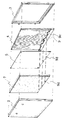
上記課題を解決するために、本発明の構造は、本体ケースと前板ケースから構成されるが、前板ケースは、本体ケースを基軸として分離結合することができるように構成する。前板ケース内部の前面にはレンチキュラー板を固定的に装着し、前板ケース若しくはレンチキュラー板、又は本体ケースの裏面には、立体用の絵を装着したり分離することができる絵固定装置を設ける。本体ケースには、たとえば、スポンジ、発泡ウレタンのような弾力素材で形成された弾力板を装着することが好ましい。上記部材群とは別途の立体用の絵を備える。上記前板ケースのレンチキュラー板の裏面の絵固定装置に上記立体用の絵を装着して立体画を随時に装着、又は分離できるようにする。 In order to solve the above-described problems, the structure of the present invention includes a main body case and a front plate case. The front plate case is configured to be separated and coupled using the main body case as a base shaft. A lenticular plate is fixedly attached to the front surface inside the front plate case, and a picture fixing device is provided on the front plate case, the lenticular plate, or the back surface of the main body case for attaching or separating a three-dimensional picture. . It is preferable to attach a resilient plate formed of a resilient material such as sponge or foamed urethane to the main body case. A separate three-dimensional picture is provided from the member group. The stereoscopic picture is attached to the picture fixing device on the back side of the lenticular plate of the front plate case so that the stereoscopic picture can be attached or separated at any time.
前記絵固定装置が位置した位置と対応する位置に立体画の固定孔の位置を形成するが、レンチキュラー板のレンズ間隔と立体画の間隔が、立体に見えるように自動的に一致する位置に構成する。絵固定装置は、レンチキュラー板4及び/又は前記本体ケース2と前記立体用の絵5との間に設けられた、装着されるときの前記立体用の絵5を、前記レンチキュラー板4を通して見たときに立体で見ることができる位置に案内する案内構造を備えている。
The position of the fixing hole of the three-dimensional image is formed at a position corresponding to the position where the picture fixing device is located, but the lens interval of the lenticular plate and the interval of the three-dimensional image are configured so as to automatically match each other so that the three-dimensional image can be seen. To do. The picture fixing device is provided between the
上記立体用の絵は、左眼用絵Rと右眼用絵Lの各々を横方向に細分化して形成した複数の左眼用小片と複数の右眼用小片の各々を横方向互い違いに順配列して一つの絵に合成した絵と同じ絵を印刷して成る。別途の紙、フィルムシートのような一般の印刷用紙に従来の一般の印刷方法で大量印刷することができるように絵を形成するが、これを独立した別のシートで構成する立体ポスター構造が提供される。 The three-dimensional picture includes a plurality of left-eye pieces and a plurality of right-eye pieces formed by subdividing each of the left-eye picture R and the right-eye picture L in the horizontal direction. It is printed by printing the same picture that is arranged and combined into one picture. A picture is formed so that it can be printed on ordinary printing paper such as separate paper and film sheets by a conventional ordinary printing method, but a three-dimensional poster structure is provided that consists of separate sheets. Is done.
また、レンチキュラー板の一部と立体用の絵の一部にモニター窓を形成して薄膜の無眼鏡立体モニターを結合して立体ポスターと立体動画を同時に視聴するようにする構造が提供される。 In addition, a structure is provided in which a monitor window is formed in a part of the lenticular plate and a part of the stereoscopic picture, and a thin-film spectacleless stereoscopic monitor is combined so that a stereoscopic poster and a stereoscopic video can be viewed simultaneously.
本発明によれば、立体用の絵を絵固定装置に固定すれば、絵固定装置によってレンチキュラー板のレンズ間隔と立体画の間隔が自動的に一致するようにすることができるため、誰でも簡単に立体画を視聴することができ、したがって、多くの場所で大量に立体画の入替えが可能で、立体用の絵を入れ替えた後に前板ケースを本体ケースに結合すればケース裏面の弾力素材が立体用の絵をレンチキュラーに密着させるため立体映像効果が直ちに示され、立体眼鏡なしに立体観測が可能であり、左眼用立体画と右眼用立体画が順に形成した上記立体画は、別途のシートで構成することにより、従来の一般の印刷方式と同一の方式で大量印刷が可能である。 According to the present invention, if a three-dimensional picture is fixed to the picture fixing device, the lens interval of the lenticular plate can be automatically matched with the three-dimensional image interval by the picture fixing device. 3D images can be viewed in many places, so it is possible to replace a large amount of 3D images in many places, and if the front case is joined to the main body case after replacing the 3D picture, the elastic material on the back of the case will be The 3D picture effect is shown immediately to bring the 3D picture into close contact with the lenticular, 3D observation is possible without 3D glasses, and the 3D picture formed by the left eye and the right eye By using this sheet, mass printing can be performed by the same method as the conventional general printing method.
したがって、レンチキュラー板の入替えなしに別途印刷した立体画だけ入れ替えても立体ポスター提供が可能で随時に多様に入替えることができ、誰でも簡単に入替えることができるため多様な3D広告を大量に入替えることができる。 Therefore, 3D posters can be provided even if only 3D images printed separately are replaced without replacing the lenticular plate, and can be replaced in various ways at any time. Can be replaced.
また、上記ポスター装置の一部に立体映像モニターを結合構成することにより、一つのポスター装置で立体ポスターと立体動画を同時に視聴することができる。 In addition, by combining a stereoscopic video monitor with a part of the poster device, it is possible to simultaneously view a stereoscopic poster and a stereoscopic video with one poster device.
以下添付した図面を参考にして本発明が属する技術分野で通常の知識を有する者が容易に実施することができるように詳しく説明する。 The present invention will be described in detail below with reference to the accompanying drawings so that those skilled in the art can easily carry it out.
しかし、本発明は様々に相異する形態で具現されることができ、ここで説明する実施例に限定されない。 However, the present invention can be embodied in various different forms and is not limited to the embodiments described herein.
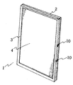
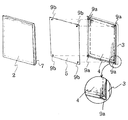
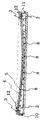
図1、図2、図5、図6、図8、図9、図10、図11、図12のようにアルミニウムフレームのような金属素材又はプラスチック素材のフレーム素材で作られた前板ケース3には、レンチキュラー板4を装着し、上記前板ケース3又はレンチキュラー板4の裏面又は本体ケース2の内部に立体用の絵5を装着することができる固定ピン9a又は固定板9c構造を構成する。
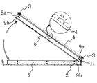
上記立体用の絵5は、図3のように別途の独立した単位の紙、又はフィルムのように一般的な印刷工程によって大量に生産が可能な素材に、左眼用絵Rと右眼用絵Lを上・下垂直方向に切れ目を入れて横方向に絵の間隔bの左眼用小片と右眼用小片とに細分化するが、その分離間隔bを上記レンチキュラー板4のレンズ間隔aと一致する間隔で細密に同一の間隔に分離し、これを、左眼用小片の隣に右眼用小片を、そのまた隣に左眼用小片のように互い違いに順に配列して一つの絵に合成した絵(原稿)と同じ絵を一般の印刷方法で印刷して立体用の絵5を完成する。
The three-
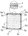
さらに詳しく説明すれば、立体用の絵5の構造は、図3の(a)のように観測者の左目に作用する左眼用絵Rと図3の(b)のように観測者の右目に作用する右眼用絵Lを図3の(c)のように横方向に細密に分離するが、左眼用絵R、右眼用絵Lのように互い違いの順序で順に配列編集する。
More specifically, the structure of the three-
このように編集された絵の原稿は、レンチキュラー板4自体に印刷するものではなく別途の独立した印刷用紙に一般の印刷のように同じ印刷工程で印刷が可能なため非常に低廉な経費で大量製作が可能である。
The edited picture manuscript is not printed on the
もちろんこの時に左眼用絵Rと右眼用絵Lの左・右の絵の間隔bは、図3、図4のレンチキュラー板4のレンズピッチaの間隔と立体映像になるように一致することができる間隔で編集する。
Of course, at this time, the interval b between the left and right pictures of the left-eye picture R and the right-eye picture L must match the distance of the lens pitch a of the
上記立体用の絵5の絵の間隔bとレンチキュラー板4のレンズピッチaの間隔は、限定はしないが立体用の絵の大きさによって異なるが、通常1‐5mの距離から視聴する立体画の絵の間隔bは0.2‐10mmであるが、バスや乗用車のように遠距離から視聴時は50mm間隔まで拡大することができる。
The interval b between the three-
立体用の絵5に形成された固定孔9b又は固定枠9dの位置は、固定ピン9a又は固定板9cに対応する位置で絵の間隔bがレンズピッチaと一致する位置としてあらかじめ計算された位置に形成する。
The position of the fixing
すなわち、図4、図5、図7のように絵の間隔bとレンズピッチaが一致する位置でレンチキュラー板4に立体画5を合わせておき、上記レンチキュラー板4に形成する。
That is, as shown in FIGS. 4, 5, and 7, the three-
絵固定装置9に形成した固定枠9cと一致する位置に立体画5の固定枠9dを構成する方法である。
In this method, the fixed
必要に応じて図5のように固定枠9dの構成を弾力板7の周囲に構成することができる。
If necessary, the structure of the fixed
図4、図6、図7のように絵の間隔bとレンズピッチaが一致する位置にレンチキュラー板4に立体画5を合わせておき、上記前板ケース3又はレンチキュラー板4に形成した固定ピン9cと一致する位置に立体画5の固定孔9bを構成する。
A fixed pin formed on the
このような上記構成は、上記レンチキュラー板4に構成された固定ピン9a又は固定板9cに上記立体画5の固定孔9b又は固定枠9dを装着すれば、レンチキュラー板4のレンズピッチaと立体用の絵5の左・右眼用絵R,Lの絵の間隔bと自動的に一致するようになるのである。すなわち、絵固定装置9は、装着されるときの立体用の絵5を、レンチキュラー板4を通して見たときに立体で見ることができる位置に案内する案内構造を備えている。
Such a configuration can be obtained by attaching the fixing
上記のような固定ピン9a又は固定板9cの構造は、上記のような論理で本体ケース2の弾力板7の周囲に構成しても同じ効果を得ることができる。
Even if the structure of the fixing
このような本発明の構造は、図1、図2、図5、図6、図7、図8、図9、図10、図11、図12のように立体掲示板1の構造を前板ケース3と本体ケース2で構成して前板ケース3は本体ケース2の一方を基軸にして蝶番のような回転装置11で連結し開け閉めするように構成するか、又は本体ケース2と前板ケース3が互いに分離又は結合が可能にロック装置10を構成することにより立体用の絵5を随時に入替えることができるのである。
Such a structure of the present invention is the same as the structure of the three-
弾力板7の構造は、たとえば、スポンジ、又は発泡ウレタンシートのような弾力素材で備える。
The structure of the
照明装置8と照明板14は、図8、図10、図12のように一般的な照明装置、すなわちLED等で備えられた薄膜の照明板14を弾力板7の前面に備えて弾力板7の弾力によって照明装置8又は照明板14と立体用の絵5を同時にレンチキュラー板4に密着するように構成する。
The illuminating device 8 and the illuminating
したがって、使用者は、本体ケース2から前板ケース3を分離して固定ピン9a又は固定板9cから立体用の絵5を分離した後、新しい立体用の絵5に入れ替え再び前板ケース3を本体ケース2に結合すれば、簡単に立体用の絵5が入替わるのであり、同時にレンチキュラー板4のレンズピッチaと立体用の絵5の絵の間隔bが絵固定装置9の案内構造の働きにより自動的に一致するようになる。
Therefore, the user separates the
また、上記のような固定ピン9a又は固定板9cの構造を本体ケース2に構成するが、その位置は前板ケース3と同じ位置に対応する本体ケース2に構成しても同じ効果である。
Further, the structure of the fixing
すなわち、レンチキュラー板4のレンズピッチaと立体用の絵5の絵の間隔bが一致する位置に形成された固定ピン9c又は固定ピン9cの構造を本体ケース2の内面に形成することができる。
That is, the fixing
次は上記構造を基本として実施した実施例である。 The following is an example implemented based on the above structure.
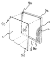
図5は、上記本発明の構造でレンチキュラー板4に立体用の絵5を固定するにおいて固定方法を多様な固定板9cの形態で実施する例である。
FIG. 5 is an example in which the fixing method is implemented in the form of various fixing
すなわち、固定板9cの形態を、図面では実施例の一つの形態として三角形で表示されているが、円形、四角形等様々な形態で構成することができる。
That is, although the form of the fixed
この場合、上記固定板9cの反対側、すなわち立体用の絵5に形成される固定枠9dの位置は、上記固定板9cに対応する位置に反対になる形態で構成する。
In this case, the opposite side of the fixed
例えば、図5のように上記固定枠9bと固定孔9dを凹形態の三角形態で形成する。
For example, as shown in FIG. 5, the fixing
さらに詳しく説明すれば、固定板9cの形態を+形態の三角形の形で構成する時は、立体用の絵5の方の固定枠9dはその反対になる−の三角形の形で形成するのである。
More specifically, when the shape of the fixing
もちろん、この時の上記固定板9cと固定枠9dの位置は、図4のようにレンチキュラー板4のレンズピッチaと立体用の絵5の左・右眼用の絵R,Lの絵の間隔bが一致する間隔に計算してその位置を形成する。
Of course, the positions of the fixing
したがって、使用者は、上記実施例のように別途に印刷した立体用の絵5にプレス工程又はパンチ工程等で固定枠9dの形状を一回の工程によって大量に形成することができる。
Therefore, the user can form a large amount of the shape of the fixed
上記のような立体用の絵5を入替える方法は、本体ケース2から前板ケース3を分離し、固定板9aから上記立体用の絵5を分離し、入れ替えようとする新しい立体用の絵5の固定枠9d部分を、上記固定板9aに立体用の絵5の固定枠9d部分を結合する方式で簡単に入替えることができるのである。
The method for replacing the three-
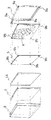
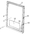
図6は、レンチキュラー板4に立体用の絵5を固定するにおいて、レンチキュラー板4又は前板ケース3の位置に選択して固定ピン9aを形成し、対応する立体用の絵5の位置に固定孔9bを形成するものである。
FIG. 6 shows that when fixing the three-
すなわち、上記レンチキュラー板4か前板ケース3の裏面の上・下部又は左・右側のうちの一部に固定ピン9aを形成するが、これに対応する立体用の絵5の固定孔9bの位置は、レンチキュラー板4と対応して左・右水平と左・右垂直方向が一致するように前板ケース3の裏面に構成する。
That is, the fixing
しかし図4のようにレンズピッチaと絵の間隔bが計算された位置に安定的に固定されることができるように上記固定ピン9aと固定孔9bを最小限2ヶ所以上の位置に形成する。
However, as shown in FIG. 4, the fixing pins 9a and the fixing
望ましくは、図6のようにレンチキュラー板4のコーナー4ヶ所に固定ピン9aを形成し、上記固定ピン9aに対応する立体用の絵5のコーナー4ヶ所に固定孔9bを形成するのが望ましい。
Desirably, fixing
このような実施例は、レンチキュラー板4のレンズピッチaと立体画5の絵の間隔bが自動的に一致するようになり、立体画5を入れ替えた次に本体ケース2を前板ケース3と結合すれば、本体ケース2に装着された弾力板7がその弾性によって立体用の絵5をレンチキュラー板4に押して密着させるようになるため、使用者は自動的に別途の調整なしに立体ポスターを大量に入れ替えて立体映像を掲示することができるのである。
In such an embodiment, the lens pitch a of the
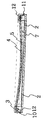
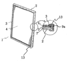
図7は、本発明の構成要素のうち前板ケース3に装着されたレンチキュラー板4に構成された固定ピン9aと固定板9c、立体用の絵5に形成された固定孔9bと固定枠9dを混合して構成されることを説明するための部分断面図である。
FIG. 7 shows a fixing
このような実施例は、上記実施例1と上記実施例2の構造が複合的に構成されたものであり、レンチキュラー板4の構造に立体用の絵5がさらに安定して決められた位置に固定されることができる長所がある。
In such an embodiment, the structure of the above-described
図8は、上記図5、図6の構造に照明板14の構造を追加した実施例である。
FIG. 8 shows an embodiment in which the structure of the
すなわち、図5のように前板ケース3にレンチキュラー板4と固定ピン9a構造を構成し、本体ケース2の構造に弾力板7を備えてその前端にLED等で構成された照明板14装置を備える。
That is, as shown in FIG. 5, the structure of the
上記照明板14の構造とレンチキュラー板4の構造の間に立体用の絵5を構成するが、立体用の絵5は印刷することができるシートとし、光が透過することができる透明フィルムで構成する。
A three-
この時、上記固定ピン9aの位置と固定孔9bの構成は、上記実施例1、2、3と同じ論理で構成することにより、レンチキュラー板4のレンズピッチaと立体画5の絵の間隔bが自動的に一致するようになり、本体ケース2の弾力板7は、その弾力によって照明板14を押し出しながら同時に立体用の絵5をレンチキュラー板4に密着させるようにして立体映像の示現が可能になるのである。
At this time, the position of the fixing
このような本発明は、図9のように前板ケース3に備えられたレンチキュラー板4を凹んだ形態の曲面形態で備える。
The present invention as described above includes the
図9、図10のような曲面形態のレンチキュラー板4構造は、前板ケース3の内部の左・右両端に形成した固定枠12に固定し、立体用の絵5を曲面形態のレンチキュラー板4構造に密着することが容易である。
The curved
したがって、この場合本体ケース2の弾力板7の構造を削除構成することができる。
Therefore, in this case, the structure of the
平面形態のレンチキュラー板4に立体用の絵5を密着する時は、レンチキュラー板4又は立体用の絵5の表面の平坦度が不均一な時に密着されない部分があり得て、この部分は立体映像にならないからである。
When the three-
上記のように、レンチキュラー板4を曲面にする時は、図10のように照明装置8による透過立体ポスター装置の構成にも効果的である。
As described above, when the
立体用の絵5をレンチキュラー板4に固定する構造は、上記実施例と同一である。
The structure for fixing the three-
図11は、停止した立体ポスター映像と無眼鏡立体映像モニター15で示される立体動画を同時に視聴することができる構造の説明図である。
FIG. 11 is an explanatory diagram of a structure capable of simultaneously viewing a stopped stereoscopic poster image and a stereoscopic moving image shown on the no-glasses
図12は、図11の構造を具体的に羅列した説明図である。 FIG. 12 is an explanatory diagram specifically listing the structure of FIG.
図11及び図12のように本体ケース2に弾力板7を装着し、照明板14構造は必要に応じて選択し、無眼鏡で立体映像を見ることができる公知の立体用映像モニター15を備え、立体用映像モニター15の画面が突出することができるようにそれぞれモニター窓16が形成された立体用の絵5とレンチキュラー板4を結合して備える。
As shown in FIGS. 11 and 12, the
固定板9cの構造と固定孔9b、固定枠9dと固定ピン9cの構成は、上記実施例の通りである。
The structure of the fixing
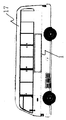
図13は乗用車、バス、バス停等に設置する構造であって、本発明を外部に設置使用する構造である。 FIG. 13 shows a structure installed in a passenger car, a bus, a bus stop, etc., and is a structure in which the present invention is installed and used outside.
上記のように外部に設置時には雨水、湿気、煤煙等から本発明の内部構造を保護しなければならない。 As described above, the internal structure of the present invention must be protected from rainwater, moisture, smoke, etc. when installed outside.
したがって上記で説明した図1、図2、図5、図6、図8、図9、図10、図11の構造に防湿枠13を備える構成である。 Therefore, it is the structure which equips the structure of FIG.1, FIG.2, FIG.5, FIG.6, FIG.8, FIG.9, FIG.10 and FIG.
すなわち図13のようにレンチキュラー板4、立体画5、固定ピン9a構造、必要によって加えられる照明板14が装着された本体ケース2及び前板ケース3構造の周囲に防湿枠13を結合する。
That is, as shown in FIG. 13, the moisture-
上記防湿枠13は、ウレタン、シリコンルーバー、ゴムのような弾力素材で構成し、防湿枠13が本体ケース2及び前板ケース3の結合された構造の周囲に被されて密着することにより、雨水が入り込むことを防止し、ほこり及び煤煙ガス等が内部に入り込むことを防止する効果がある。
The moisture-
特に照明板14構造が結合構成されている時、その効果が倍になる。
In particular, when the structure of the
このような実施例は、立体用の絵5の入替え時は、上記防湿枠13をはずし前板ケース3を開いて固定ピン9aで立体用の絵5を入れ替えた後、前板ケース3を閉じて防湿枠13を再び被せればよい。
In such an embodiment, when the three-
固定板9c構造と固定孔9b、固定枠9dと固定ピン9cの構成は上記実施例の通りである。
The structure of the fixed
したがってこのような実施例は、大型支持台と結合して道路面等又は建物の壁等に付ける大型立体広告にもその実用性がある。 Therefore, such an embodiment also has practicality in a large three-dimensional advertisement attached to a road surface or the like or a wall of a building in combination with a large support base.
上記実施例1から実施例7までの構造をタクシーや乗用車等の立体広告装置として使用することができる。 The structure from the first embodiment to the seventh embodiment can be used as a three-dimensional advertising device such as a taxi or a passenger car.
すなわち、図14のように乗用車13の上段、又は後面、側面等、必要位置に1個又は複数個の形態で付着することができ、乗用車13の屋根の位置に3個の立体掲示板1構造で三角形態等で構成することができる。
That is, as shown in FIG. 14, one or a plurality of forms can be attached to a necessary position such as an upper stage of a
上記のような構成は、図13で説明した防湿枠13構造で構成する時さらに効果的である。
The above configuration is more effective when configured with the moisture-
このような実施例で固定板9c構造と固定孔9b、固定枠9dと固定ピン9cの構成も上記実施例の通りである。
In this embodiment, the structure of the fixing
図15のようにバス17の後面又は両面に図1、図2、図5、図6、図8、図9、図10、図13の構造のうち選択構成する。 As shown in FIG. 15, the structure shown in FIG. 1, FIG. 2, FIG. 5, FIG. 6, FIG.
特に図13のように防湿枠13構造が結合された構造をバス17に装着する時は、雨水防止、防湿防止、煤煙ガスが入り込むことを防止することができるためさらに効果的である。
In particular, when the structure having the moisture-
このような実施例で上記で実施した固定板9c構造と固定孔9b、固定枠9dと固定ピン9cの構成は上記実施例の通りにする。
The structure of the fixing
図16の実施例は、円形の柱に設置するか又は円形形態で本発明を応用して実施する構造に関するものである。 The embodiment of FIG. 16 relates to a structure that is installed on a circular pillar or is applied by applying the present invention in a circular form.
すなわち図1、図2、図5、図6、図8、図9、図10、図13の構造を曲面状態にして分割枠21によって2分割又は3分割、4分割構造に分割し、このような分割構造は分離枠6単位で構成するものである。 That is, the structure shown in FIG. 1, FIG. 2, FIG. 5, FIG. 6, FIG. 8, FIG. 9, FIG. A simple divided structure is constituted by 6 separate frames.
すなわち、図16のようにレンチキュラー板4、立体画5、弾力板7、必要によって加えられる照明板14等が装着された本体ケース2及び前板ケース3をすべて曲面で構成して分離枠6によって本体ケース2からレンチキュラー板4と前板ケース2を分離又は結合する。
That is, as shown in FIG. 16, the
このような実施例で、固定板9c構造と固定孔9b、固定枠9dと固定ピン9cの構成もまた上記実施例の通りである。
In such an embodiment, the structure of the fixing
したがって、このような本発明は、劇場、地下鉄内の3Dポスター装置、屋外3D広告装置、乗用車やバスの3Dポスター装置としてその活用性が高く、立体画を一般の印刷方式で印刷して簡便で低廉かつ大量に印刷した立体用の絵を手軽に簡単に大量に入替えることができるため、その経済性及び実用性が非常に高い。 Therefore, the present invention is highly useful as a 3D poster device in a theater, a subway, an outdoor 3D advertising device, and a 3D poster device for a passenger car or a bus. Since it is possible to easily and easily replace a large number of three-dimensional pictures that are inexpensive and printed in large quantities, its economic efficiency and practicality are very high.
1.立体掲示板、2.本体ケース、3.前板ケース、4.レンチキュラー板、5.立体用の絵、6.分離枠、7.弾力板、8.照明装置、9.絵固定装置、9a.固定ピン、9b.固定孔、9c.固定板、9d.固定枠、10.ロック装置、11.回転装置、12.固定枠、13.防湿枠、14.照明板、15.立体映像モニター、16.モニター窓、17.バス、18.乗用車、R:左眼用絵、L 右眼用絵、a.レンズピッチ、b.絵の間隔 1. 3D bulletin board, 2. 2. Body case Front plate case, 4. 4. Lenticular plate, 3D picture, 6. Separation frame, 7. Elastic plate, 8. 8. lighting device; Picture fixing device, 9a. Fixing pin, 9b. Fixing hole, 9c. Fixing plate, 9d. Fixed frame, 10. 10. locking device; Rotating device, 12. Fixed frame, 13. Moisture-proof frame, 14. Illumination plate, 15. 3D image monitor, 16. Monitor window, 17. Bus, 18. Passenger car, R: picture for left eye, L picture for right eye, a. Lens pitch, b. Picture interval
Claims (16)
前記前板ケース3と前記本体ケース2の間に配されるレンチキュラー板4と、
前記レンチキュラー板4と前記本体ケースの間に装着される立体用の絵5と、
前記レンチキュラー板4及び/又は前記本体ケース2と前記立体用の絵5との間に設けられた、装着されるときの前記立体用の絵5を、前記レンチキュラー板4を通して見たときに立体で見ることができる位置に案内する案内構造を備えた絵固定装置9と、
を含んで構成することにより、
前記本体ケース2に対し前記前板ケース3を開くことにより、前記立体用の絵5を随時に入替えることができる
ことを特徴とする絵の交換が可能な立体ポスター装置。 A front plate case 3 and a body case 2 having a frame structure;
A lenticular plate 4 disposed between the front plate case 3 and the main body case 2;
A three-dimensional picture 5 mounted between the lenticular plate 4 and the main body case;
When the three-dimensional picture 5 provided between the lenticular plate 4 and / or the main body case 2 and the three-dimensional picture 5 is viewed through the lenticular plate 4 in a three-dimensional manner. A picture fixing device 9 having a guide structure for guiding to a position where it can be seen;
By including
A three-dimensional poster device capable of exchanging pictures, wherein the three-dimensional picture 5 can be replaced at any time by opening the front plate case 3 with respect to the main body case 2.
ことを特徴とする請求項1に記載の絵の交換が可能な立体ポスター装置。 The three-dimensional picture 5 is composed of a plurality of left-eye pieces and a plurality of right-eye pieces formed by subdividing each of the left-eye picture R and the right-eye picture L in the horizontal direction. The three-dimensional poster device capable of exchanging pictures according to claim 1, wherein the picture is the same as the picture synthesized in order and combined into one picture.
レンチキュラー板4のレンズピッチaと立体用の絵5の絵の間隔bが一致する位置に固定するように装着された固定板9cが本体ケース2の内面に形成されたことを含むことを特徴とする請求項1に記載の絵の交換が可能な立体ポスター装置。 In the first item, the fixing plate 9c mounted so as to be fixed at a position where the lens pitch a of the lenticular plate 4 and the interval b of the three-dimensional picture 5 coincide with each other is formed on the inner surface of the main body case 2. The three-dimensional poster device capable of exchanging pictures according to claim 1.
前記前板ケース3と前記本体ケース2の間に配されるレンチキュラー板4と、
前記レンチキュラー板4と前記本体ケースの間に装着される立体用の絵5と、
前記レンチキュラー板4及び/又は前記本体ケース2と前記立体用の絵5との間に設けられた、装着されるときの前記立体用の絵5を、前記レンチキュラー板4を通して見たときに立体で見ることができる位置に案内する案内構造を備えた絵固定装置9と、
前板ケース3が結合されたケースの外部に弾力素材で形成された防湿枠13と、を含む
ことを特徴とする絵の交換が可能な立体ポスター装置。 A front plate case 3 and a body case 2 having a frame structure;
A lenticular plate 4 disposed between the front plate case 3 and the main body case 2;
A three-dimensional picture 5 mounted between the lenticular plate 4 and the main body case;
When the three-dimensional picture 5 provided between the lenticular plate 4 and / or the main body case 2 and the three-dimensional picture 5 is viewed through the lenticular plate 4 in a three-dimensional manner. A picture fixing device 9 having a guide structure for guiding to a position where it can be seen;
A three-dimensional poster device capable of exchanging pictures, comprising: a moisture-proof frame 13 formed of an elastic material outside the case to which the front plate case 3 is coupled.
立体広告構造で使用することを特徴とする請求項13に記載の絵の交換が可能な立体ポスター装置 The three-dimensional poster device capable of exchanging pictures according to claim 13, wherein the structure according to claim 13 is used in a three-dimensional advertisement structure outside a road or the like.
Applications Claiming Priority (6)
| Application Number | Priority Date | Filing Date | Title |
|---|---|---|---|
| KR20110018341 | 2011-03-02 | ||
| KR10-2011-0018341 | 2011-03-02 | ||
| KR10-2011-0025691 | 2011-03-23 | ||
| KR20110025691 | 2011-03-23 | ||
| KR1020110030524A KR101303414B1 (en) | 2011-03-02 | 2011-04-04 | image changeable 3D steroscopic poster apparatus |
| KR10-2011-0030524 | 2011-04-04 |
Publications (1)
| Publication Number | Publication Date |
|---|---|
| JP2012181520A true JP2012181520A (en) | 2012-09-20 |
Family
ID=45813969
Family Applications (1)
| Application Number | Title | Priority Date | Filing Date |
|---|---|---|---|
| JP2012030117A Pending JP2012181520A (en) | 2011-03-02 | 2012-02-15 | Solid poster device allowing picture replacement |
Country Status (4)
| Country | Link |
|---|---|
| US (1) | US20120224259A1 (en) |
| JP (1) | JP2012181520A (en) |
| CN (1) | CN102654960B (en) |
| GB (1) | GB2488626B (en) |
Families Citing this family (8)
| Publication number | Priority date | Publication date | Assignee | Title |
|---|---|---|---|---|
| PL403496A1 (en) * | 2013-04-10 | 2014-10-13 | Sławomir Strojnowski | Showcase sheet with the image exerting on the observer the impression of three-dimensional image |
| CN103342060B (en) * | 2013-06-18 | 2016-01-20 | 坤达国际有限公司 | A kind of three-dimensional image printed matter and three-dimensional image printing process |
| FR3013130B1 (en) * | 2013-11-08 | 2016-01-01 | Philippe Sagniez | PLATINUM DOOR VIEW |
| CN103926700A (en) * | 2014-03-19 | 2014-07-16 | 玉晶光电股份有限公司 | Stereoscopic image display apparatus |
| KR101688433B1 (en) * | 2014-09-02 | 2016-12-21 | 현대모비스 주식회사 | Automobile lamp having floating lighting image |
| CN105226514B (en) * | 2015-10-28 | 2018-06-19 | 南车株洲电力机车有限公司 | A kind of erecting device of electrical appliance screen cabinet and its inlet wire cable |
| CA3208733C (en) | 2018-03-01 | 2025-05-06 | Smartrend Manufacturing Group (Smg), Inc. | Illuminated signs for vehicles, mounting systems therefor and related methods |
| US11168856B2 (en) * | 2020-03-30 | 2021-11-09 | Ford Global Technologies, Llc | Customizable vehicle exterior lamps |
Citations (11)
| Publication number | Priority date | Publication date | Assignee | Title |
|---|---|---|---|---|
| JPH09179221A (en) * | 1995-12-27 | 1997-07-11 | Photo Kurafutoshiya:Kk | Picture frame with lenticular lens |
| JPH10282593A (en) * | 1997-04-02 | 1998-10-23 | Victor Co Of Japan Ltd | Holder for stereoscopic image recording medium |
| JPH10282591A (en) * | 1997-04-03 | 1998-10-23 | Victor Co Of Japan Ltd | Film for recording stereoscopic image |
| JP2003084230A (en) * | 2001-09-07 | 2003-03-19 | Canon Inc | Display device |
| JP2003344807A (en) * | 2002-05-27 | 2003-12-03 | Nittatsu Co Ltd | Display instrument using lenticular lens |
| CN2624243Y (en) * | 2003-05-29 | 2004-07-07 | 厦门象屿照路进出口有限公司 | Camera accompanied by three-dimensional diagram |
| CN2696071Y (en) * | 2003-11-17 | 2005-04-27 | 刘宁 | Stereo-image advertisment box capable of changing picture |
| JP2005208118A (en) * | 2004-01-20 | 2005-08-04 | Ito Bigeisha Seihansho:Kk | Manufacturing method of design display apparatus |
| CN1828363A (en) * | 2005-03-02 | 2006-09-06 | 唐·S.·卡特曼 | Interactive Audio and Visual Displays |
| JP2006301061A (en) * | 2005-04-18 | 2006-11-02 | Tanaka Sangyo Kk | Lenticular sheet assembly structure and method of using the same |
| EP2228678A1 (en) * | 2009-01-22 | 2010-09-15 | Koninklijke Philips Electronics N.V. | Display device with displaced frame perception |
Family Cites Families (15)
| Publication number | Priority date | Publication date | Assignee | Title |
|---|---|---|---|---|
| FR2611071B1 (en) * | 1987-02-18 | 1991-10-31 | Villard Jean | LUMINOUS SIGN FOR GROUND ADVERTISING |
| US5782347A (en) * | 1994-04-01 | 1998-07-21 | Insight, Inc. | Box container systems and display frames with multiple view optics |
| JP2957086B2 (en) * | 1994-04-28 | 1999-10-04 | 稔 稲葉 | Slide mount |
| US5823344A (en) * | 1995-07-31 | 1998-10-20 | Insight, Inc. | Display systems with multiple view optics |
| US6989931B2 (en) * | 1998-07-22 | 2006-01-24 | Rosenthal Bruce A | Lenticular optical system |
| US6843009B2 (en) * | 2000-11-21 | 2005-01-18 | Daniel B. Kainen | Lenticular folding card, card case, and book |
| US6865033B2 (en) * | 2001-04-24 | 2005-03-08 | Owen Laverty | Lenticular display device |
| WO2004111703A1 (en) * | 2003-05-21 | 2004-12-23 | Mckinley William R | Device for displaying lenticular displays |
| IL165313A0 (en) * | 2004-11-21 | 2006-01-15 | Lenticular display sheet with interchangeable print | |
| US7788834B2 (en) * | 2005-05-07 | 2010-09-07 | Welch Stephen R | Wearable article having a backlit lenticular display |
| US8089564B2 (en) * | 2006-04-05 | 2012-01-03 | Studio One Entertainment, Inc. | Studio booth configured to produce illusion that customer is photographed in different locale |
| JP2008046525A (en) * | 2006-08-21 | 2008-02-28 | Noriji Ooishi | Stereoscopic image photographing apparatus and display device |
| FR2905475A1 (en) * | 2006-09-01 | 2008-03-07 | Franck Andre Marie Guigan | Image e.g. moving picture, display device for e.g. three-dimensional TV, has lenticular array including set of elementary optical devices each with convergent elementary lens, and screw to adjust dimensions of image to dimensions of array |
| IL179731A0 (en) * | 2006-11-30 | 2007-05-15 | Itzchak Bar Yona | Lenticular display device |
| US7971377B2 (en) * | 2006-12-07 | 2011-07-05 | Qun Zheng | Lenticular image display |
-
2012
- 2012-01-13 GB GB1200549.2A patent/GB2488626B/en not_active Expired - Fee Related
- 2012-01-17 US US13/351,267 patent/US20120224259A1/en not_active Abandoned
- 2012-02-06 CN CN201210025513.9A patent/CN102654960B/en not_active Expired - Fee Related
- 2012-02-15 JP JP2012030117A patent/JP2012181520A/en active Pending
Patent Citations (11)
| Publication number | Priority date | Publication date | Assignee | Title |
|---|---|---|---|---|
| JPH09179221A (en) * | 1995-12-27 | 1997-07-11 | Photo Kurafutoshiya:Kk | Picture frame with lenticular lens |
| JPH10282593A (en) * | 1997-04-02 | 1998-10-23 | Victor Co Of Japan Ltd | Holder for stereoscopic image recording medium |
| JPH10282591A (en) * | 1997-04-03 | 1998-10-23 | Victor Co Of Japan Ltd | Film for recording stereoscopic image |
| JP2003084230A (en) * | 2001-09-07 | 2003-03-19 | Canon Inc | Display device |
| JP2003344807A (en) * | 2002-05-27 | 2003-12-03 | Nittatsu Co Ltd | Display instrument using lenticular lens |
| CN2624243Y (en) * | 2003-05-29 | 2004-07-07 | 厦门象屿照路进出口有限公司 | Camera accompanied by three-dimensional diagram |
| CN2696071Y (en) * | 2003-11-17 | 2005-04-27 | 刘宁 | Stereo-image advertisment box capable of changing picture |
| JP2005208118A (en) * | 2004-01-20 | 2005-08-04 | Ito Bigeisha Seihansho:Kk | Manufacturing method of design display apparatus |
| CN1828363A (en) * | 2005-03-02 | 2006-09-06 | 唐·S.·卡特曼 | Interactive Audio and Visual Displays |
| JP2006301061A (en) * | 2005-04-18 | 2006-11-02 | Tanaka Sangyo Kk | Lenticular sheet assembly structure and method of using the same |
| EP2228678A1 (en) * | 2009-01-22 | 2010-09-15 | Koninklijke Philips Electronics N.V. | Display device with displaced frame perception |
Also Published As
| Publication number | Publication date |
|---|---|
| GB2488626B (en) | 2015-07-29 |
| GB201200549D0 (en) | 2012-02-29 |
| US20120224259A1 (en) | 2012-09-06 |
| CN102654960B (en) | 2016-06-22 |
| GB2488626A (en) | 2012-09-05 |
| CN102654960A (en) | 2012-09-05 |
Similar Documents
| Publication | Publication Date | Title |
|---|---|---|
| JP2012181520A (en) | Solid poster device allowing picture replacement | |
| JP2003156712A (en) | Image display device | |
| JP2002521734A (en) | Device for displaying images for a moving observer | |
| JP2008129592A (en) | Screen for forming three-dimensional image | |
| CN103777352A (en) | Head up display | |
| CN201562078U (en) | Stereoscopic image imaging device | |
| CN106104662A (en) | Microphone accessory, microphone accessory components, and method of using the microphone | |
| CN112542106A (en) | Stereo display lamp box | |
| US4500088A (en) | 3D Display | |
| KR101303414B1 (en) | image changeable 3D steroscopic poster apparatus | |
| CN102298257A (en) | Stereoscopic rear projection display equipment | |
| CN108140342A (en) | Information display | |
| CN215117023U (en) | Space stereo display equipment | |
| RU114212U1 (en) | INFORMATION ADVERTISING AND ENTERTAINMENT UNIT | |
| CN102568355A (en) | LED (light-emitting diode) holographic projection vehicle | |
| KR100793812B1 (en) | Advertising device using lenticular sheet or parallax barrier | |
| JP3138493U (en) | Display materials such as signboards | |
| WO2014168496A1 (en) | Sheets display case producing images appearing as 3-d to the viewer | |
| KR20060035298A (en) | Multiple or stereoscopic image display device and method using lens sheet | |
| WO2005124432A1 (en) | Dynamic lenticular display unit | |
| US20030024142A1 (en) | Lenticular device containing an integral shuttering method for displaying an image, a series of which form an animated display when moving relative to an observer | |
| CN201946263U (en) | Advertising machine | |
| EP1473688A2 (en) | A method and system for outdoor advertising | |
| KR20090002380U (en) | Multi image display device | |
| CN102136230A (en) | Method for generating three-dimensional effect for planar picture outside moving object |
Legal Events
| Date | Code | Title | Description |
|---|---|---|---|
| A621 | Written request for application examination |
Free format text: JAPANESE INTERMEDIATE CODE: A621 Effective date: 20150106 |
|
| A977 | Report on retrieval |
Free format text: JAPANESE INTERMEDIATE CODE: A971007 Effective date: 20151118 |
|
| A131 | Notification of reasons for refusal |
Free format text: JAPANESE INTERMEDIATE CODE: A131 Effective date: 20151124 |
|
| A601 | Written request for extension of time |
Free format text: JAPANESE INTERMEDIATE CODE: A601 Effective date: 20160208 |
|
| A521 | Request for written amendment filed |
Free format text: JAPANESE INTERMEDIATE CODE: A523 Effective date: 20160524 |
|
| A131 | Notification of reasons for refusal |
Free format text: JAPANESE INTERMEDIATE CODE: A131 Effective date: 20161025 |
|
| A521 | Request for written amendment filed |
Free format text: JAPANESE INTERMEDIATE CODE: A523 Effective date: 20170125 |
|
| A02 | Decision of refusal |
Free format text: JAPANESE INTERMEDIATE CODE: A02 Effective date: 20170627 |