JP2012185176A - 離脱可能な電流クランプを備える電気測定器 - Google Patents
離脱可能な電流クランプを備える電気測定器 Download PDFInfo
- Publication number
- JP2012185176A JP2012185176A JP2012124888A JP2012124888A JP2012185176A JP 2012185176 A JP2012185176 A JP 2012185176A JP 2012124888 A JP2012124888 A JP 2012124888A JP 2012124888 A JP2012124888 A JP 2012124888A JP 2012185176 A JP2012185176 A JP 2012185176A
- Authority
- JP
- Japan
- Prior art keywords
- current
- clamp
- measuring instrument
- probe
- holding member
- Prior art date
- Legal status (The legal status is an assumption and is not a legal conclusion. Google has not performed a legal analysis and makes no representation as to the accuracy of the status listed.)
- Granted
Links
Images



Classifications
-
- G—PHYSICS
- G01—MEASURING; TESTING
- G01R—MEASURING ELECTRIC VARIABLES; MEASURING MAGNETIC VARIABLES
- G01R1/00—Details of instruments or arrangements of the types included in groups G01R5/00 - G01R13/00 and G01R31/00
- G01R1/02—General constructional details
- G01R1/06—Measuring leads; Measuring probes
- G01R1/067—Measuring probes
- G01R1/06788—Hand-held or hand-manipulated probes, e.g. for oscilloscopes or for portable test instruments
-
- G—PHYSICS
- G01—MEASURING; TESTING
- G01R—MEASURING ELECTRIC VARIABLES; MEASURING MAGNETIC VARIABLES
- G01R1/00—Details of instruments or arrangements of the types included in groups G01R5/00 - G01R13/00 and G01R31/00
- G01R1/20—Modifications of basic electric elements for use in electric measuring instruments; Structural combinations of such elements with such instruments
- G01R1/22—Tong testers acting as secondary windings of current transformers
-
- G—PHYSICS
- G01—MEASURING; TESTING
- G01R—MEASURING ELECTRIC VARIABLES; MEASURING MAGNETIC VARIABLES
- G01R1/00—Details of instruments or arrangements of the types included in groups G01R5/00 - G01R13/00 and G01R31/00
- G01R1/02—General constructional details
- G01R1/04—Housings; Supporting members; Arrangements of terminals
-
- G—PHYSICS
- G01—MEASURING; TESTING
- G01R—MEASURING ELECTRIC VARIABLES; MEASURING MAGNETIC VARIABLES
- G01R15/00—Details of measuring arrangements of the types provided for in groups G01R17/00 - G01R29/00, G01R33/00 - G01R33/26 or G01R35/00
- G01R15/14—Adaptations providing voltage or current isolation, e.g. for high-voltage or high-current networks
- G01R15/18—Adaptations providing voltage or current isolation, e.g. for high-voltage or high-current networks using inductive devices, e.g. transformers
Landscapes
- Physics & Mathematics (AREA)
- General Physics & Mathematics (AREA)
- Engineering & Computer Science (AREA)
- Power Engineering (AREA)
- Measuring Instrument Details And Bridges, And Automatic Balancing Devices (AREA)
- Measurement Of Current Or Voltage (AREA)
Abstract
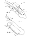
【解決手段】電流クランプ測定器100は、電流測定器本体114と、離脱可能な電流クランプ110とを備える。電流測定器本体114及び電流クランプ110は、電流クランプ110が電流測定器本体114から離脱可能であって、電流クランプ110を、電流測定器本体114に取り付けた状態であっても、電流測定器本体114から離脱させた状態であっても、電流の測定が可能に構成される。
【選択図】図2A−2B
Description
の状況で測定を行うために、技術者は、表示部を見るのに十分な時間だけ自らを強制的に不都合な位置に置くことで、表示部を迅速に確認することが可能であり、あるいは測定器が表示部上に測定値を保持する機能を有する場合、技術者は、測定が行われた後に測定器を不都合な位置または見難い位置から移動させ、保持された測定値を見ることが可能である。これらの解決策は、明らかな不利点を有している。一方の事例では、技術者が、不都合な位置にある測定器の表示部上の測定値を見ようと試みるときに、技術者は、身体的に不快で潜在的に危険な位置に自らを置かなければならない。他方の事例では、クランプすることがそもそも困難な配線から測定器を取り外すことが不便であり、同じ配線から追加的に測定を行うためにクランプ測定器を再びクランプしなければならない場合、多大な時間を必要とする可能性がある。その上、始動電流の測定、あるいは断続的な電流負荷の検出などといった実時間測定が望まれるところでは、連続して測定する間、測定器を所定位置に保持しなければならない。
ェースは、例えば、測定値や、動作モード、デバイス及びバッテリの状態などの情報を表示するための表示部132を含んでいる。ユーザインターフェースは、ユーザからの入力を受け付けると共に、例えば測定器のオン/オフや、動作モードの選択、測定範囲の選択、測定の実行といった測定器における機能を実行するために用いられ得る複数のボタン134をさらに含んでいる。本実施形態においては、複数のボタン134を含んでいるものの、他の実施形態においては、例えば、ダイヤルや、サムホイール、スイッチなどの付加的あるいは代替的なユーザ入力デバイスが用いられてもよい。さらに、ユーザ入力デバイスは、図1Aに示されている位置とは異なる位置に配置されてもよい。本体114上に、オプションとしてのライト140を含んでもよく、暗い環境下で配線の配置や配線のクランプを補助するために、クランププローブ110の方向を照らすようにライト140を配置してもよい。ライト140は、例えば、フィラメント式光源や発光ダイオード(“LED”)光源などの従来の光源を使用できる。また同様に他のタイプの光源も使用可能である。ライト140は、複数のボタン134の1つを用いてスイッチがオン/オフされるように設計されてもよい。
Claims (21)
- 電流測定器本体と、
電流クランプと
を備え、
前記電流測定器本体は、入力信号から電流測定値を算出動作可能な回路を含み、
前記電流クランプは、前記電流測定器本体内に含まれている前記回路に電気的に接続され、電流を検出して、前記入力信号を供給し、
前記電流測定器本体及び前記電流クランプは、前記電流クランプを前記電流測定器本体から離脱可能であり、前記電流クランプを前記電流測定器本体に取り付けた状態であっても、前記電流クランプを前記電流測定器本体から離脱させた状態であっても、前記電流クランプを動作可能に構成されている
ことを特徴とする電流クランプ測定器。 - 請求項1に記載の電流クランプ測定器であって、
前記電流測定器本体は、
第1のクランプ保持部材と、
第2のクランプ保持部材と
を備え、
前記第1のクランプ保持部材及び前記第2のクランプ保持部材は、前記電流クランプが前記電流測定器本体に取り付けられたときに、前記第1のクランプ保持部材と前記第2のクランプ保持部材との間に、前記電流クランプが配置される領域を規定する
ことを特徴とする電流クランプ測定器。 - 請求項2に記載の電流クランプ測定器であって、
前記第1のクランプ保持部材、及び前記第2のクランプ保持部材は、
取り付けられた前記電流クランプの一部分に係合するように構成されている
ことを特徴とする電流クランプ測定器。 - 請求項2に記載の電流クランプ測定器であって、
前記第1のクランプ保持部材、及び前記第2のクランプ保持部材は、
前記電流クランプのレバー部分を露出させる切り欠き部をそれぞれ備えている
ことを特徴とする請求項2に記載の電流クランプ測定器。 - 請求項2に記載の電流クレーム測定器であって、
前記第1のクランプ保持部材、及び前記第2のクランプ保持部材はそれぞれ、個別の突起部を備え、
該個別の突起部は、前記電流クランプが前記電流測定器本体に取り付けられたときに該電流クランプの開口部分から予め設定された距離を隔てるように、前記第1のクランプ保持部材上及び前記第2のクランプ保持部材上に形成されている
ことを特徴とする電流クレーム測定器。 - 請求項1に記載の電流クランプ測定器であって、
前記電流クランプは、配線によって前記回路に電気的に接続され、
前記電流測定器本体は、さらに、前記配線を巻き付け可能な部分を備えるように構成されている
ことを特徴とする電流クランプ測定器。 - 請求項6に記載の電流クランプ測定器であって、
前記配線が巻き付けられる、前記電流測定器本体の前記部分は、前記配線が巻かれたと
きに前記配線を受け入れる少なくとも1つの凹部を含んでいる
ことを特徴とする電流クランプ測定器。 - 請求項1に記載の電流クランプ測定器であって、
前記電流測定器本体に含まれている前記回路は、
前記入力信号を受信するように構成された信号調整回路と、
前記電流測定値を算出動作可能な処理装置と
を備えることを特徴とする電流クランプ測定器。 - 電流プローブと、
計器ハウジングであって、前記電流プローブを受け入れて、該電流プローブを離脱可能に保持するように構成されたプローブ保持部材を備え、さらに、該プローブ保持部材が、該電流プローブを該プローブ保持部材から離脱可能であり、該電流プローブを、該プローブ保持部材に保持させても、該プローブ保持部材から離脱させても使用可能に構成された、計器ハウジングと、
該ハウジング内に配置され、前記電流プローブに接続された測定回路と
を備えることを特徴とする手持ち式電気測定器。 - 請求項9に記載の試験計器であって、
前記プローブ保持部材は、本体から延在する、第1の部材と第2の部材とを備え、
前記電流プローブは、前記第1の部材と前記第2の部材との間に保持される
ことを特徴とする試験計器。 - 請求項10に記載の試験計器であって、
前記第1の部材及び前記第2の部材の各々は、ガイドが形成された内面を備え、
前記電流プローブは、前記第1の部材及び前記第2の部材によって保持されたときに、前記ガイドに当接する
ことを特徴とする試験計器。 - 請求項9に記載の試験計器であって、
前記電流プローブを前記試験回路に電気的に接続するように構成された配線をさらに備え、
前記ハウジングは、前記プローブ保持部材によって前記配線が保持されるときに、前記配線を巻き付け可能な部分をさらに備えている
ことを特徴とする試験計器。 - 請求項12に記載の試験計器であって、
前記配線を巻き付け可能な前記部分は、該配線が巻き付けられたときに該配線を受け入れる少なくとも1つの凹部を規定するように構成された、前記ハウジングの後部を備えている
ことを特徴とする試験計器。 - 請求項9に記載の試験計器であって、
前記プローブ保持部材は、前記保持された電流プローブに係合する部分を含んでいる
ことを特徴とする試験計器。 - 請求項9に記載の試験計器であって、
前記電流プローブは、電流クランプを備えている
ことを特徴とする試験計器。 - 請求項15に記載の試験計器であって、
前記電流クランプは、先細りの外形を有している
ことを特徴とする試験計器。 - 電流クランプ測定器を操作する方法であって、
電流クランプ測定器のハウジングに離脱可能に取り付けられた電流クランププローブを離脱させることと、
第1の導体に前記電流クランププローブを取り付けることと、
前記第1の導体内の第1の電流を測定することと、
前記電流クランプを前記電流クランプ測定器のハウジングに再び取り付けることと、
前記電流クランプを前記ハウジングに取り付けているときに、該電流クランプを第2の導体に取り付けることと、
前記第2の導体内の第2の電流を測定することと
を備えることを特徴とする方法。 - 請求項17に記載の方法であって、
前記電流クランプを前記電流クランプ測定器の前記ハウジングに再び取り付けることは、前記電流クランプを前記ハウジングにおける複数の保持部材の間に配置させることを備えている
ことを特徴とする方法。 - 請求項18に記載の方法であって、
前記電流クランプを前記電流クランプ測定器の前記ハウジングに再び取り付けることは、前記電流クランプを前記ハウジングにおける複数の前記クランプ保持部材に係合させることをさらに備えている
ことを特徴とする方法。 - 請求項18に記載の方法であって、
前記電流クランプを前記ハウジングに取り付けているときに、該電流クランプを第2の導体に取り付けることは、該クランプを開けるために、該電流クランプにおけるレバーの露出された部分に圧力を加えることを備えている
ことを特徴とする方法。 - 請求項17に記載の方法であって、
前記電流クランププローブに電気的に接続された配線を前記ハウジングの一部分に巻きつけることをさらに備えている
ことを特徴とする方法。
Applications Claiming Priority (2)
| Application Number | Priority Date | Filing Date | Title |
|---|---|---|---|
| US11/414,655 | 2006-04-27 | ||
| US11/414,655 US7439726B2 (en) | 2006-04-27 | 2006-04-27 | Electrical measuring instrument having detachable current clamp probe |
Related Parent Applications (1)
| Application Number | Title | Priority Date | Filing Date |
|---|---|---|---|
| JP2009507889A Division JP5039778B2 (ja) | 2006-04-27 | 2007-04-12 | 離脱可能な電流クランプを備える電気測定器 |
Publications (2)
| Publication Number | Publication Date |
|---|---|
| JP2012185176A true JP2012185176A (ja) | 2012-09-27 |
| JP5497847B2 JP5497847B2 (ja) | 2014-05-21 |
Family
ID=38647724
Family Applications (2)
| Application Number | Title | Priority Date | Filing Date |
|---|---|---|---|
| JP2009507889A Active JP5039778B2 (ja) | 2006-04-27 | 2007-04-12 | 離脱可能な電流クランプを備える電気測定器 |
| JP2012124888A Active JP5497847B2 (ja) | 2006-04-27 | 2012-05-31 | 離脱可能な電流クランプを備える電気測定器 |
Family Applications Before (1)
| Application Number | Title | Priority Date | Filing Date |
|---|---|---|---|
| JP2009507889A Active JP5039778B2 (ja) | 2006-04-27 | 2007-04-12 | 離脱可能な電流クランプを備える電気測定器 |
Country Status (7)
| Country | Link |
|---|---|
| US (3) | US7439726B2 (ja) |
| EP (1) | EP2016429B1 (ja) |
| JP (2) | JP5039778B2 (ja) |
| CN (1) | CN101467052A (ja) |
| BR (1) | BRPI0710766B1 (ja) |
| TW (1) | TWI329204B (ja) |
| WO (1) | WO2007127617A2 (ja) |
Cited By (4)
| Publication number | Priority date | Publication date | Assignee | Title |
|---|---|---|---|---|
| JP2016090490A (ja) * | 2014-11-10 | 2016-05-23 | 日置電機株式会社 | フレキシブルセンサおよび測定装置 |
| WO2018163487A1 (ja) * | 2017-03-06 | 2018-09-13 | 株式会社シーブイエンジニアリング | 電流測定装置 |
| JP2020076706A (ja) * | 2018-11-09 | 2020-05-21 | 日置電機株式会社 | フレキシブルセンサ及び測定装置 |
| CN114924107A (zh) * | 2022-05-13 | 2022-08-19 | 安徽科盟电子科技有限公司 | 一种无线钳形电流检测装置及其检测方法 |
Families Citing this family (44)
| Publication number | Priority date | Publication date | Assignee | Title |
|---|---|---|---|---|
| US7851758B1 (en) | 2005-09-29 | 2010-12-14 | Flir Systems, Inc. | Portable multi-function inspection systems and methods |
| US7439726B2 (en) | 2006-04-27 | 2008-10-21 | Fluke Corporation | Electrical measuring instrument having detachable current clamp probe |
| US7557559B1 (en) * | 2006-06-19 | 2009-07-07 | Seektech, Inc. | Compact line illuminator for locating buried pipes and cables |
| FI121522B (fi) * | 2007-06-06 | 2010-12-15 | Abb Oy | Menetelmä taajuusmuuttajayksikön ohjaamiseksi ja taajuusmuuttajakokoonpano |
| US9383394B2 (en) | 2007-11-02 | 2016-07-05 | Cooper Technologies Company | Overhead communicating device |
| CA2717860C (en) * | 2008-03-07 | 2016-11-08 | Milwaukee Electric Tool Corporation | Battery pack for use with a power tool and a non-motorized sensing tool |
| EP2275827B1 (en) * | 2009-07-17 | 2025-03-19 | Fluke Corporation | Clamp-on multimeters including a rogowski coil for measuring alternating current in a conductor |
| US9615147B2 (en) | 2010-05-17 | 2017-04-04 | Flir Systems, Inc. | Multisensory meter system |
| US20110304319A1 (en) * | 2010-06-09 | 2011-12-15 | Brymen Technology Corporation | Multimeter with flexible current sensor |
| US20120020049A1 (en) * | 2010-07-22 | 2012-01-26 | Hsin-Chen Ko | Hook-type electric meter capable of providing light source |
| CN103250060A (zh) | 2010-08-10 | 2013-08-14 | 库柏技术公司 | 用于安装悬置装置的设备和方法 |
| CN102012447B (zh) * | 2010-10-12 | 2012-04-18 | 邢台供电公司 | 伸缩式钳形电流表 |
| CA2755468A1 (en) * | 2010-10-18 | 2012-04-18 | Milwaukee Electric Tool Corporation | Clamp meter with detachable clamp and clamp storage area |
| JP5588319B2 (ja) * | 2010-11-24 | 2014-09-10 | 日置電機株式会社 | クランプ式測定器、及びクランプセンサ |
| CN102109565B (zh) * | 2010-12-20 | 2013-04-03 | 山东电力集团公司超高压公司 | Ct二次回路智能检测仪 |
| US8922195B2 (en) * | 2010-12-30 | 2014-12-30 | Fluke Corporation | Simplified jaw assembly for a clamp meter |
| USD683248S1 (en) * | 2012-01-27 | 2013-05-28 | Fluke Corporation | R-coil, temperature and voltage modules with wireless transmitter |
| US10095659B2 (en) * | 2012-08-03 | 2018-10-09 | Fluke Corporation | Handheld devices, systems, and methods for measuring parameters |
| CN103675359B (zh) * | 2012-09-11 | 2018-06-08 | 福禄克精密测量有限公司 | 用于电池测试仪的无线手柄及包含该手柄的电池测试仪组件 |
| JP6054710B2 (ja) * | 2012-11-08 | 2016-12-27 | 日置電機株式会社 | 接地抵抗計 |
| US9379556B2 (en) | 2013-03-14 | 2016-06-28 | Cooper Technologies Company | Systems and methods for energy harvesting and current and voltage measurements |
| CN105408898B (zh) | 2013-03-15 | 2019-05-28 | 弗兰克公司 | 测量数据的自动记录和图形生成 |
| US9188606B2 (en) | 2013-04-29 | 2015-11-17 | Keysight Technologies, Inc. | Oscilloscope current probe with interchangeable range and sensitivity setting modules |
| USD719040S1 (en) | 2013-07-12 | 2014-12-09 | Milwaukee Electric Tool Corporation | Electrical tester |
| USD724976S1 (en) | 2013-12-31 | 2015-03-24 | Milwaukee Electric Tool Corporation | Electrical tester |
| US9664708B2 (en) | 2014-01-09 | 2017-05-30 | Milwaukee Electric Tool Corporation | Test and measurement device including grooves for receiving probes in a use position |
| US9671433B2 (en) | 2014-04-25 | 2017-06-06 | Infineon Technologies Ag | Current sensor devices and methods |
| US9410933B2 (en) * | 2014-05-29 | 2016-08-09 | The United States of America a represented by the Secretary of Navy | Method and apparatus for determining the salinity of a sample |
| WO2016013021A1 (en) * | 2014-07-25 | 2016-01-28 | Selec Controls Pvt. Ltd. | Current transformer assembly with attachable functional adaptor |
| CN104297550A (zh) * | 2014-09-17 | 2015-01-21 | 国家电网公司 | 杆式钳形电流测量仪 |
| CN105510671B (zh) * | 2014-09-24 | 2020-10-30 | 福禄克公司 | 钳表及钳状探头 |
| USD797107S1 (en) * | 2015-07-02 | 2017-09-12 | Datalogic Ip Tech S.R.L. | Portable terminal |
| CN205003199U (zh) * | 2015-09-02 | 2016-01-27 | 丹纳赫(上海)工业仪器技术研发有限公司 | 便携式测量装置 |
| US10228393B2 (en) * | 2016-02-15 | 2019-03-12 | Kane Usa, Inc. | Slide closure multi tester |
| US10267833B2 (en) * | 2016-11-02 | 2019-04-23 | Equinix, Inc. | Power monitoring probe for monitoring power distribution in an electrical system |
| CN107576825B (zh) * | 2017-08-21 | 2024-01-30 | 贵州电网有限责任公司 | 一种变径直流、回路电阻测试夹 |
| US11513154B2 (en) * | 2018-08-31 | 2022-11-29 | Black & Decker Inc. | System and apparatus for monitoring the performance of an electrically powered device |
| CN111474398A (zh) * | 2020-04-27 | 2020-07-31 | 南宁学院 | 一种便于携带和检测的万用表 |
| CN114280390B (zh) * | 2020-09-27 | 2024-12-03 | 安徽国润电力有限公司 | 一种电路故障用排查装置 |
| US11614470B2 (en) * | 2020-11-05 | 2023-03-28 | U-Haul International, Inc. | Non-invasive current sensing device |
| WO2022155613A1 (en) * | 2021-01-15 | 2022-07-21 | Essenlix Corporation | Imaging based assay accuracy improvement through guided training |
| CN114563597B (zh) * | 2022-02-28 | 2025-02-28 | 广东电网有限责任公司 | 一种万能表 |
| CN119256233A (zh) * | 2022-05-23 | 2025-01-03 | 理想工业公司 | 具有电路追踪器、插座测试器和/或负载连续性测试器的集成工具 |
| US20260063667A1 (en) * | 2024-08-30 | 2026-03-05 | Horizon Global Americas Inc. | Non-invasive wire testing device |
Citations (2)
| Publication number | Priority date | Publication date | Assignee | Title |
|---|---|---|---|---|
| US4259635A (en) * | 1979-06-08 | 1981-03-31 | Triplett William R | Electrical continuity and voltage testing device having a pair of probes spaced for insertion into an electrical socket |
| JP2004361248A (ja) * | 2003-06-04 | 2004-12-24 | Midori Anzen Co Ltd | クランプ型漏れ電流計 |
Family Cites Families (16)
| Publication number | Priority date | Publication date | Assignee | Title |
|---|---|---|---|---|
| US3555420A (en) * | 1967-09-06 | 1971-01-12 | Soss Mfg Co | Voltage testing instrument |
| US3840808A (en) | 1973-04-30 | 1974-10-08 | Tif Instr Inc | Clamp-on electrical meter |
| US4079314A (en) * | 1974-10-12 | 1978-03-14 | Woo Chul Jone | Pincette type multi-tester |
| JPS5622964A (en) * | 1979-07-31 | 1981-03-04 | Matsushita Electric Works Ltd | Clamp meter |
| US4378525A (en) | 1980-09-18 | 1983-03-29 | Burdick Neal M | Method and apparatus for measuring a DC current in a wire without making a direct connection to the wire |
| US5170114A (en) * | 1991-09-11 | 1992-12-08 | Myron Zucker, Inc. | Harmonimeter input circuit and methods of constructing and utilizing same |
| JPH06242171A (ja) * | 1993-02-18 | 1994-09-02 | Yukio Goto | 漏電回路検出器 |
| US5477133A (en) * | 1993-07-29 | 1995-12-19 | Etcon Corporation | Device for measuring a wide range of voltages and for determining continuity using visual and tactile indicators |
| US6229315B1 (en) * | 1995-05-25 | 2001-05-08 | Stephen J. Briggs | Hand-held harmonics detector |
| US6043640A (en) * | 1997-10-29 | 2000-03-28 | Fluke Corporation | Multimeter with current sensor |
| WO2000024108A1 (en) * | 1998-10-16 | 2000-04-27 | Century Mfg. Co. | Portable battery charger including auto-polarity switch |
| US6137285A (en) * | 1998-11-30 | 2000-10-24 | Applied Power, Inc. | Electrical voltage tester |
| US7242173B2 (en) * | 2004-08-31 | 2007-07-10 | Fluke Corporation | Combined test instrument probe and voltage detector |
| US7327133B2 (en) * | 2005-09-21 | 2008-02-05 | Universal Enterprises, Inc. | Current measuring device using hall sensors |
| US7530277B2 (en) * | 2006-01-30 | 2009-05-12 | Hioki Denki Kabushiki Kaisha | Measuring apparatus |
| US7439726B2 (en) | 2006-04-27 | 2008-10-21 | Fluke Corporation | Electrical measuring instrument having detachable current clamp probe |
-
2006
- 2006-04-27 US US11/414,655 patent/US7439726B2/en not_active Expired - Lifetime
-
2007
- 2007-04-12 EP EP07760556.6A patent/EP2016429B1/en active Active
- 2007-04-12 WO PCT/US2007/066519 patent/WO2007127617A2/en not_active Ceased
- 2007-04-12 JP JP2009507889A patent/JP5039778B2/ja active Active
- 2007-04-12 CN CNA2007800210510A patent/CN101467052A/zh active Pending
- 2007-04-12 BR BRPI0710766-8A patent/BRPI0710766B1/pt active IP Right Grant
- 2007-04-19 TW TW096113838A patent/TWI329204B/zh active
- 2007-05-25 US US11/753,852 patent/US7312603B2/en not_active Expired - Lifetime
-
2008
- 2008-10-20 US US12/254,765 patent/US7659710B2/en not_active Expired - Lifetime
-
2012
- 2012-05-31 JP JP2012124888A patent/JP5497847B2/ja active Active
Patent Citations (2)
| Publication number | Priority date | Publication date | Assignee | Title |
|---|---|---|---|---|
| US4259635A (en) * | 1979-06-08 | 1981-03-31 | Triplett William R | Electrical continuity and voltage testing device having a pair of probes spaced for insertion into an electrical socket |
| JP2004361248A (ja) * | 2003-06-04 | 2004-12-24 | Midori Anzen Co Ltd | クランプ型漏れ電流計 |
Cited By (7)
| Publication number | Priority date | Publication date | Assignee | Title |
|---|---|---|---|---|
| JP2016090490A (ja) * | 2014-11-10 | 2016-05-23 | 日置電機株式会社 | フレキシブルセンサおよび測定装置 |
| WO2018163487A1 (ja) * | 2017-03-06 | 2018-09-13 | 株式会社シーブイエンジニアリング | 電流測定装置 |
| JP2018146406A (ja) * | 2017-03-06 | 2018-09-20 | 株式会社シーブイエンジニアリング | 電流測定装置 |
| US11002769B2 (en) | 2017-03-06 | 2021-05-11 | CVEngineering Corporation | Current measurement device |
| JP2020076706A (ja) * | 2018-11-09 | 2020-05-21 | 日置電機株式会社 | フレキシブルセンサ及び測定装置 |
| JP7311261B2 (ja) | 2018-11-09 | 2023-07-19 | 日置電機株式会社 | フレキシブルセンサ及び測定装置 |
| CN114924107A (zh) * | 2022-05-13 | 2022-08-19 | 安徽科盟电子科技有限公司 | 一种无线钳形电流检测装置及其检测方法 |
Also Published As
| Publication number | Publication date |
|---|---|
| WO2007127617A2 (en) | 2007-11-08 |
| JP5497847B2 (ja) | 2014-05-21 |
| TW200745569A (en) | 2007-12-16 |
| US7659710B2 (en) | 2010-02-09 |
| JP5039778B2 (ja) | 2012-10-03 |
| BRPI0710766A2 (pt) | 2011-06-07 |
| CN101467052A (zh) | 2009-06-24 |
| EP2016429A2 (en) | 2009-01-21 |
| EP2016429B1 (en) | 2021-01-13 |
| US20090039870A1 (en) | 2009-02-12 |
| EP2016429A4 (en) | 2017-07-12 |
| TWI329204B (en) | 2010-08-21 |
| US7312603B2 (en) | 2007-12-25 |
| US20070252579A1 (en) | 2007-11-01 |
| WO2007127617A3 (en) | 2008-10-09 |
| US7439726B2 (en) | 2008-10-21 |
| JP2009535623A (ja) | 2009-10-01 |
| US20070252578A1 (en) | 2007-11-01 |
| BRPI0710766B1 (pt) | 2018-07-10 |
Similar Documents
| Publication | Publication Date | Title |
|---|---|---|
| JP5039778B2 (ja) | 離脱可能な電流クランプを備える電気測定器 | |
| EP3567382B1 (en) | Clamp probe for non-contact electrical parameter measurement | |
| US8232805B2 (en) | Battery sensor unit and method for manufacturing the battery sensor unit | |
| US8922195B2 (en) | Simplified jaw assembly for a clamp meter | |
| US7109700B2 (en) | Multimeter having off-device display device and selection device | |
| US11662368B2 (en) | Non-contact voltage measurement with adjustable size Rogowski coil | |
| JPH09189723A (ja) | 平行コードの電流検査装置 | |
| EP2275827B1 (en) | Clamp-on multimeters including a rogowski coil for measuring alternating current in a conductor | |
| JP2013032974A (ja) | コンセント測定プローブ及び電圧測定器 | |
| JP2007303952A (ja) | 電流測定装置 | |
| EP3862761A1 (en) | Sensor probe with clamp having adjustable interior region for non-contact electrical measurement | |
| JP2008215900A (ja) | 非接触電流計及びその測定補助具 | |
| TW201230561A (en) | Plug for a wiring duct | |
| US20170276706A1 (en) | Apparatus to tap the electrical signals in process control without breaking the continuity | |
| JP4641988B2 (ja) | 検電器 | |
| JP2013113822A (ja) | 測定装置 | |
| KR101468110B1 (ko) | 팔목착용이 가능한 멀티미터 | |
| JP5986549B2 (ja) | 電流検知装置 | |
| KR20000018039A (ko) | 전압 및 전류 표시기를 갖는 케이블장치 | |
| JP2003028903A (ja) | 電子式電力量計 | |
| JP2004354297A (ja) | ウェアラブルテスター | |
| JPH10170547A (ja) | プローブ・アダプタ |
Legal Events
| Date | Code | Title | Description |
|---|---|---|---|
| A521 | Request for written amendment filed |
Free format text: JAPANESE INTERMEDIATE CODE: A523 Effective date: 20120629 |
|
| A621 | Written request for application examination |
Free format text: JAPANESE INTERMEDIATE CODE: A621 Effective date: 20120629 |
|
| A131 | Notification of reasons for refusal |
Free format text: JAPANESE INTERMEDIATE CODE: A131 Effective date: 20130604 |
|
| A521 | Request for written amendment filed |
Free format text: JAPANESE INTERMEDIATE CODE: A523 Effective date: 20130829 |
|
| TRDD | Decision of grant or rejection written | ||
| A01 | Written decision to grant a patent or to grant a registration (utility model) |
Free format text: JAPANESE INTERMEDIATE CODE: A01 Effective date: 20140204 |
|
| A61 | First payment of annual fees (during grant procedure) |
Free format text: JAPANESE INTERMEDIATE CODE: A61 Effective date: 20140306 |
|
| R150 | Certificate of patent or registration of utility model |
Ref document number: 5497847 Country of ref document: JP Free format text: JAPANESE INTERMEDIATE CODE: R150 |
|
| RD02 | Notification of acceptance of power of attorney |
Free format text: JAPANESE INTERMEDIATE CODE: R3D02 |
|
| R250 | Receipt of annual fees |
Free format text: JAPANESE INTERMEDIATE CODE: R250 |
|
| R250 | Receipt of annual fees |
Free format text: JAPANESE INTERMEDIATE CODE: R250 |
|
| R250 | Receipt of annual fees |
Free format text: JAPANESE INTERMEDIATE CODE: R250 |
|
| R250 | Receipt of annual fees |
Free format text: JAPANESE INTERMEDIATE CODE: R250 |
|
| R250 | Receipt of annual fees |
Free format text: JAPANESE INTERMEDIATE CODE: R250 |
|
| R250 | Receipt of annual fees |
Free format text: JAPANESE INTERMEDIATE CODE: R250 |
|
| R250 | Receipt of annual fees |
Free format text: JAPANESE INTERMEDIATE CODE: R250 |
|
| R250 | Receipt of annual fees |
Free format text: JAPANESE INTERMEDIATE CODE: R250 |
|
| R250 | Receipt of annual fees |
Free format text: JAPANESE INTERMEDIATE CODE: R250 |
|
| R250 | Receipt of annual fees |
Free format text: JAPANESE INTERMEDIATE CODE: R250 |