JP2012187200A - Washing machine - Google Patents
Washing machine Download PDFInfo
- Publication number
- JP2012187200A JP2012187200A JP2011051717A JP2011051717A JP2012187200A JP 2012187200 A JP2012187200 A JP 2012187200A JP 2011051717 A JP2011051717 A JP 2011051717A JP 2011051717 A JP2011051717 A JP 2011051717A JP 2012187200 A JP2012187200 A JP 2012187200A
- Authority
- JP
- Japan
- Prior art keywords
- washing
- protrusions
- pulsator
- water
- tub
- Prior art date
- Legal status (The legal status is an assumption and is not a legal conclusion. Google has not performed a legal analysis and makes no representation as to the accuracy of the status listed.)
- Abandoned
Links
Images



Landscapes
- Main Body Construction Of Washing Machines And Laundry Dryers (AREA)
Abstract
【課題】通常よりも低い水位で洗濯する場合に、布いたみや布からみを抑制し、且つ、洗浄力が低下しない洗濯機を提供する。
【解決手段】洗濯機は、洗濯兼脱水槽5と、パルセータ41と、洗濯脱水モータ42と、複数の突起91とを備えている。洗濯兼脱水槽5は、側部31と底部32とを有している。パルセータ41は洗濯兼脱水槽5の底部32に回転可能に配設されており、洗濯脱水モータ42はパルセータ41を回転させる。複数の突起91は、洗濯兼脱水槽5の内側における底部32の外周に設けられている。底部32の中心からパルセータ41の先端までの距離をdとして、底部32の中心から複数の突起91までの距離をDとすると、D≦1.5dである。
【選択図】図5The present invention provides a washing machine that suppresses fabric sag and squeezing when washing is performed at a lower water level than usual and does not reduce the cleaning power.
A washing machine includes a washing / dehydrating tub 5, a pulsator 41, a washing / dehydrating motor 42, and a plurality of protrusions 91. The washing and dewatering tub 5 has a side portion 31 and a bottom portion 32. The pulsator 41 is rotatably disposed at the bottom 32 of the washing / dehydrating tub 5, and the washing / dehydrating motor 42 rotates the pulsator 41. The plurality of protrusions 91 are provided on the outer periphery of the bottom portion 32 inside the washing and dewatering tub 5. When the distance from the center of the bottom 32 to the tip of the pulsator 41 is d, and the distance from the center of the bottom 32 to the plurality of protrusions 91 is D, D ≦ 1.5d.
[Selection] Figure 5
Description
本発明は、通常よりも低い水位で少量の洗濯物を洗濯する場合に布いたみ、布からみを防止する構造を備えた洗濯機に関する。 The present invention relates to a washing machine having a structure that prevents cloth from being squeezed and squeezed when washing a small amount of laundry at a lower water level than usual.
布いたみを防止する洗濯機は、例えば、特許文献1に記載されている。この特許文献1に記載された洗濯機は、洗濯槽と、洗濯槽の中央底部に設けられたパルセータと、洗濯槽の内壁に設けられた段部と、段部に取り付けられるネットを備えている。段部に取り付けられたネットは、パルセータの上方に配置される。
A washing machine that prevents fabric damage is described in
この特許文献1に記載された洗濯機では、洗濯物をネットの上に載せて洗濯することにより、パルセータに洗濯物を直接接触させないようにして、布いたみや洗濯物の型くずれを防止する。
In the washing machine described in
洗濯物の種類や量に応じて水流の強弱を調整可能な洗濯機は、例えば、特許文献2に記載されている。この特許文献2に記載された洗濯機は、洗濯槽に主動パルセータと従動パルセータを備えている。そして、洗濯物の量が多くて洗濯負荷荷重が大きい場合には、主動パルセータと従動パルセータの両方を回転させて強い水流を発生させ、洗濯負荷荷重が小さい場合には、主動パルセータのみを回転させて弱い水流を発生させる。
A washing machine that can adjust the strength of the water flow according to the type and amount of the laundry is described in
しかしながら、特許文献1に記載された洗濯機は、洗濯物をネットの上に載せるため、少量の洗濯物を洗濯する場合であっても、水位を高くしなければならない。その結果、少量の洗濯物を洗濯する場合に、水の使用量を削減することができなかった。
However, since the washing machine described in
また、特許文献2に記載された洗濯機は、少量の洗濯物を低い水位で洗う場合に、主動パルセータ及び従動パルセータに洗濯物が接触しやすくなり、布いたみの原因となる。
さらに、少量の洗濯物を洗う場合に水流を弱くすると、洗浄力が低下するため、例えば泥汚れの靴下等の高い洗浄力を必要とする少量の洗濯物を洗濯するには不向きであった。
In addition, the washing machine described in
Further, when the water flow is weakened when washing a small amount of laundry, the cleaning power is reduced, so that it is unsuitable for washing a small amount of laundry that requires high cleaning power, such as mud-stained socks.
本発明の目的は、上記従来技術における実情を考慮し、通常よりも低い水位で洗濯する場合に、布いたみや布からみを抑制し、且つ、洗浄力が低下しない洗濯機を提供することにある。 An object of the present invention is to provide a washing machine that suppresses fabric sag and tangling and does not reduce detergency when washing is performed at a lower water level than usual in consideration of the situation in the prior art. .
上記課題を解決し、本発明の目的を達成するため、本発明の洗濯機は、洗濯槽と、攪拌翼と、駆動部と、複数の突起とを備えている。
洗濯槽は、側部と底部とを有している。攪拌翼は洗濯槽の底部に回転可能に配設されており、駆動部は攪拌翼を回転させる。複数の突起は、洗濯槽の内側における底部の外周に設けられている。
底部の中心から攪拌翼の先端までの距離をdとして、底部の中心から複数の突起までの距離をDとすると、D≦1.5dである。
In order to solve the above problems and achieve the object of the present invention, the washing machine of the present invention includes a washing tub, a stirring blade, a drive unit, and a plurality of protrusions.
The washing tub has a side portion and a bottom portion. The stirring blade is rotatably arranged at the bottom of the washing tub, and the driving unit rotates the stirring blade. The plurality of protrusions are provided on the outer periphery of the bottom portion inside the washing tub.
If the distance from the center of the bottom part to the tip of the stirring blade is d, and the distance from the center of the bottom part to the plurality of protrusions is D, D ≦ 1.5d.
上記構成の洗濯機では、洗濯槽に供給された水に攪拌翼の回転方向に沿った第1の水流が発生する。この第1の水流により洗濯槽の内側における底部の外周へ移動した水は、複数の突起によってせき止められ、洗濯槽の側部に沿って上昇し、洗濯槽の中心へ向かう。これにより、洗濯槽の上下方向に回転する第2の水流が発生するので、通常よりも低い水位で洗濯しても、攪拌翼が水面から突出することがない。したがって、攪拌翼に洗濯物が引っ掛からないようにすることができ、布いたみや布からみを抑制することができる。 In the washing machine configured as described above, a first water flow is generated in the water supplied to the washing tub along the rotation direction of the stirring blade. The water that has moved to the outer periphery of the bottom inside the washing tub by the first water flow is blocked by a plurality of protrusions, rises along the side of the washing tub, and moves toward the center of the washing tub. Thereby, since the 2nd water flow which rotates to the up-down direction of a washing tub is generated, even if it wash | cleans by the water level lower than usual, a stirring blade does not protrude from the water surface. Therefore, it is possible to prevent the laundry from being caught on the stirring blade, and it is possible to suppress the fabric damage and the tangling.
また、底部の中心から攪拌翼の先端までの距離をdとし、底部の中心から複数の突起までの距離をDとして、D≦1.5dに設定する。これにより、複数の突起を攪拌翼に近接させることができる。その結果、複数の突起間にせき止められる水の容量を十分に確保することができ、第2の水流を確実に発生させることができる。 Further, D is set to D ≦ 1.5d, where d is the distance from the center of the bottom to the tip of the stirring blade and D is the distance from the center of the bottom to the plurality of protrusions. Thereby, a some protrusion can be made to adjoin to a stirring blade. As a result, a sufficient capacity of water blocked between the plurality of protrusions can be ensured, and the second water flow can be reliably generated.
第2の水流は、洗濯槽内の水の水圧が低い程強くなるため、通常よりも低い水位で洗濯する場合に効率よく発生する。したがって、通常よりも低い水位で洗濯する場合に、第1の水流と第2の水流によって洗濯物の移動を活発に行わせることができ、高い洗浄力を確保することができる。 Since the second water flow becomes stronger as the water pressure in the washing tub is lower, the second water flow is efficiently generated when washing is performed at a lower water level than usual. Therefore, when washing is performed at a lower water level than usual, the laundry can be actively moved by the first water flow and the second water flow, and a high detergency can be secured.
上記構成の洗濯機によれば、通常よりも低い水位で洗濯する場合に、布いたみや布からみを抑制し、且つ、洗浄力を低下させないようにすることができる。 According to the washing machine having the above-described configuration, when washing is performed at a lower water level than usual, it is possible to suppress fabric scumming and fabric squeezing and not to reduce the cleaning power.
以下、本発明の洗濯機を実施するための形態について、図1〜図7を参照して説明する。なお、各図において共通の部材には、同一の符号を付している。 Hereinafter, the form for implementing the washing machine of this invention is demonstrated with reference to FIGS. In addition, the same code | symbol is attached | subjected to the common member in each figure.
<洗濯機の構成>
まず、洗濯機の構成について、図1及び図2を参照して説明する。
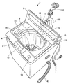
図1は、本発明の洗濯機の一実施形態を示す外観構成図である。図2は、本発明の洗濯機の一実施形態を示す縦断面図である。
<Structure of washing machine>
First, the structure of a washing machine is demonstrated with reference to FIG.1 and FIG.2.
FIG. 1 is an external configuration diagram showing an embodiment of a washing machine of the present invention. FIG. 2 is a longitudinal sectional view showing an embodiment of the washing machine of the present invention.
図1に示すように、洗濯機1は、外枠2と、外枠2を支持するベース3(図2参照)と、外枠2の上に設けられたトップカバー4と、外枠2内に配置された洗濯兼脱水槽5と、トップカバー4に取り付けられ、洗濯兼脱水槽5を開閉する蓋6を備えている。
As shown in FIG. 1, the
トップカバー4には、給水接続口11と、注水ケース12と、柔軟剤ケース13と、液体投入口14と、表示パネル15と、電源スイッチ16が設けられている。
The top cover 4 is provided with a water
給水接続口11、注水ケース12及び柔軟剤ケース13は、トップカバー4の後側に配置されている。給水接続口11は、給水ホース101を介して蛇口102に接続される。また、給水接続口11は、給水電磁弁18を介して注水ケース12に接続されている。蛇口102から供給される水は、給水電磁弁18を開放することにより注水ケース12を通って洗濯兼脱水槽5へ注水される。
The water
柔軟剤ケース13は、柔軟剤を貯留する柔軟剤用タンクと、ソフナー供給電磁弁13a(図3参照)を有している。柔軟剤用タンクは、ソフナー供給電磁弁13aを介して給水接続口11に接続されており、ソフナー供給電磁弁13aは、柔軟剤用タンク内への水の供給を制御する。通常、最終すすぎ時にソフナー供給電磁弁13aが開放され、給水接続口11から柔軟剤用タンク内に水が供給される。これにより、柔軟剤用タンク内の柔軟剤は、供給された水と一緒に洗濯兼脱水槽5へ流れ込む。
The
液体投入口14、表示パネル15及び電源スイッチ16は、トップカバー4の前側に配置されている。液体投入口14には、液体洗剤や液体の漂白剤などが投入される。液体投入口14に投入された液体洗剤や液体の漂白剤などは、後述する洗剤流下路37を通って洗濯兼脱水槽5へ流れ込む。
The
表示パネル15には、運転内容をセットするための各種入力スイッチが設けられている。電源スイッチ16は、表示パネル15の側方に配置されている。使用者は、電源スイッチ16を操作して洗濯機1の電源を入れてから、表示パネル15の各種入力スイッチを操作して運転内容を決定する。この運転内容としては、例えば、水量の決定や、洗い運転、すすぎ運転、脱水運転の選択、運転時間の決定等を挙げることができる。
The
図2に示すように、外枠2の内部の上側には、コーナー支持部21が設けられており、このコーナー支持部21に吊棒22が垂下されている。吊棒22は、防振ばね23を介して外槽24を防振支持するために用いられる。外槽24の最上部には、外槽カバー25が設けられている。
As shown in FIG. 2, a
洗濯兼脱水槽5は、外槽24の内側に設けられている。この洗濯兼脱水槽5は、有底筒状に形成されており、金属(ステンレス)で形成された側部31と、合成樹脂で形成された底部32とを備えている。洗濯兼脱水槽5の側部31は、ネジ33(図5参照)によって底部32に固定されている。
The washing / dehydrating
側部31は、略円筒状に形成されており、複数の脱水穴31aを有している。この側部31の上部には、脱水時の振動を防止するバランサ35と、洗剤トレー36が設けられている。洗剤トレー36は、洗剤を投入するために開閉可能に構成されており、洗剤流下路37に連通している。洗剤流下路37は、洗濯兼脱水槽5の側部31に沿って下方に延在し、底部32の外側に開口する洗剤排出口38を有する。
The
洗剤トレー36に投入された洗剤は、注水ケース12から洗剤トレー36に注がれた水と混じり合って洗剤流下路37を流下し、洗剤排出口38から外槽24及び洗濯兼脱水槽5に流入する。これにより、洗剤が水に混じって早く溶解するため、洗剤の化学力(洗濯物の汚れを分離させる力)を有効に発揮させることができ、高い洗浄効果を得ることができる。
The detergent put into the
底部32は、有底筒状に形成されている(図5参照)。この底部32には、複数の突起91(図4参照)が設けられている。複数の突起91については、後で詳しく説明する。
The bottom 32 is formed in a bottomed cylindrical shape (see FIG. 5). The bottom 32 is provided with a plurality of protrusions 91 (see FIG. 4). The plurality of
底部32の中央には、攪拌翼の一具体例であるパルセータ41が配置されている。このパルセータ41は、駆動部の一具体例を示す洗濯脱水モータ42によって左周り及び左回りに交互に回転される。洗濯脱水モータ42は、例えばDCブラシレスモータであり、フランジ43と、回転主軸44と、内側回転軸45とを有している。洗濯脱水モータ42は、フランジ43によって外槽24の底部における外面に固定されている。
In the center of the bottom 32, a
回転主軸44は、洗濯兼脱水槽5の底部32に固定される底面フランジ44aを有している。この底面フランジ44aを底部32に固定することで、回転主軸44は、洗濯兼脱水槽5を支持する。内側回転軸45は、洗濯兼脱水槽5の底部32を貫通している。この内側回転軸45の先端部には、パルセータ41が固定されている。
The rotation
回転主軸44と内側回転軸45の回転駆動は、回転伝達切り替え機構(図示せず)で切り替えられる。洗い運転及びすすぎ運転では、内側回転軸のみが左周り及び右周りに交互に回転駆動される。これにより、パルセータ41が左周り及び右周りに交互に回転し、洗濯兼脱水槽5に貯留された水に水流が発生する。その結果、洗濯兼脱水槽5内の洗濯物103が洗濯される。
The rotation drive of the rotation
また、脱水運転では、回転主軸44のみが回転駆動される。これにより、洗濯兼脱水槽5が回転し、洗濯物103に含まれる水分が遠心力によって脱水される。脱水された水分は、脱水穴31aから外槽24へ放出され、排水ホース47を通って機外へ排出される。脱水運転では、回転主軸44を高速で回転駆動させる。このとき、洗濯物103の片寄りによって生じる洗濯兼脱水槽5内のアンバランスな状態がバランサ35で解消されるため、洗濯兼脱水槽5内がアンバランスな状態の場合に生じる異常振動が緩和される。
In the dehydration operation, only the rotation
排水ホース47は、外槽24の底部に設けられた排水口24aに接続されている。この排水ホース47には、排水電磁弁48が設けられている。外槽24及び洗濯兼脱水槽5に水を貯留する場合は、排水電磁弁48が閉じられる。洗い運転やすすぎ運転で使用された水は、排水電磁弁48を開放することにより、排水口24aから排水ホース47を通って機外へ排水される。
The
また、脱水運転時は、排水電磁弁48を開放する。これにより、洗濯物103から脱水された水は、脱水穴31aから外槽24へ放出され、排水口24aから排水ホース47を通って機外へ排水される。
Further, during the dehydrating operation, the drain
トップカバー4の前側の内部には、コントロール基板51と、水位センサー52が設けられている。コントロール基板51には、電源スイッチ16が実装されている。また、コントロール基板51は、排水電磁弁48の開閉、洗濯脱水モータ42の駆動等を制御する。洗濯脱水モータ42の駆動制御としては、例えば、回転主軸44及び内側回転軸45の回転駆動の開始、停止及び回転速度調整等がある。
A
水位センサー52は、圧力チューブ53を介してエアートラップ54の空気室55に連通されている。水位センサー52は、空気室55を介して外槽24内に貯留された水の水圧を検知し、その検知結果を水位情報としてコントロール基板51に送信する。コントロール基板51は、受信した水位情報と運転内容に応じた水量に基づいて給水電磁弁18の開閉を制御し、給水量を調整する。
The
<洗濯機の制御回路>
次に、洗濯機1の制御回路について、図3を参照して説明する。
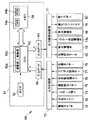
図3は、洗濯機1の制御回路を示すブロック図である。
<Washing machine control circuit>
Next, the control circuit of the
FIG. 3 is a block diagram showing a control circuit of the
制御回路60は、コントロール基板51(図2参照)に設けられている。この制御回路60は、マイクロコンピュータによって構成された制御ユニット部61と、入力回路部70と、出力駆動回路部71とを有する。
制御ユニット部61は、CPU(中央制御部)62と、タイマ63と、メモリ64と、入力ポート65と、出力ポート66とを備えている。CPU62は、演算部62aと、制御部62bとを有し、メモリ64は、RAM64aと、ROM64bとを有する。
The
The
入力回路部70には、電源スイッチ16と、水位センサー52と、ICホール素子74と、蓋開閉センサー75と、全自動選択キー76と、マニュアル設定キー77と、布量センサー78とが接続されている。各種のスイッチやセンサーから出力された情報信号は、それぞれ入力回路部70を介して制御ユニット部61に入力される。
The
出力駆動回路部71には、洗濯脱水モータ42と、給水電磁弁18と、ソフナー供給電磁弁13aと、排水電磁弁48と、蓋ロックソレノイド79と、終了ブザー80とが接続されている。洗濯脱水モータ42や排水電磁弁48等の各種電気機器は、出力駆動回路部71を通じて供給される電力で作動する。
The output drive circuit unit 71 is connected to the washing / dehydrating
<突起及び水流の説明>
次に、洗濯兼脱水槽5に設けられた複数の突起91について、図4〜図6を参照して説明する。また、洗濯兼脱水槽に発生する水流について、図7及び図8を参照して説明する。
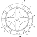
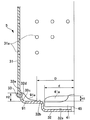
図4は、洗濯兼脱水槽5の平面図である。図5は、洗濯兼脱水槽5の部分縦断面図である。図6は、洗濯兼脱水槽5に設けられた複数の突起91の斜視図である。図7は、複数の突起91を設けない洗濯兼脱水槽5Aにおける洗濯時の水流を示した説明図である。
<Explanation of protrusion and water flow>
Next, the plurality of
FIG. 4 is a plan view of the washing and
図4に示すように、パルセータ41の回転中心は、底部32の中心に一致している。複数の突起91は、洗濯兼脱水槽5の内側における底部32の外周に設けられている。これら複数の突起91は、底部32の中心に対して放射状に配置されており、底部32の周方向に等間隔で並んでいる。また、複数の突起91は、底部32の中心を挟んで対向するように配置されている。
As shown in FIG. 4, the rotation center of the
図5に示すように、底部32は、有底筒状に形成されており、パルセータ41が挿入される凹部32aと、凹部32aの周囲に形成される底面32bを有している。また、底面32bの縁部に連続する曲率半径R1の曲面32cと、曲面32cに連続する側面32dと、側面32dに連続する端面32eを有している。
As shown in FIG. 5, the
複数の突起91は、底部32の底面32b、曲面32c及び側面32dに沿って形成される。複数の突起91は、底部32の曲面32cに向かって凹む曲率半径R2の曲面91aを有しており、パルセータ41側に向かうにつれて低くなるように傾斜している。
これにより、パルセータ41の回転方向に移動する洗濯物103(図2参照)が、複数の突起91を容易に乗り越えることができる。その結果、複数の突起91に洗濯物103が引っ掛かって滞留することを防ぎ、布いたみや布からみを抑制することができる。
The plurality of
Thereby, the laundry 103 (refer FIG. 2) which moves to the rotation direction of the
突起91における曲面91aの曲率半径R2は、底部32における曲面32cの曲率半径R1よりも大きくなっている(R2>R1)。
これにより、洗濯兼脱水槽5の径方向に流れる洗濯物103が複数の突起91に引っ掛からずに上昇することができ、洗濯物103の滞留を防止或いは抑制することができる。その結果、布いたみや布からみを抑制することができる。
The curvature radius R2 of the
Thereby, the
複数の突起91の側部は、パルセータ41の回転方向に沿った第1の水流C1(図8参照)により底部32外周へ移動した水をせき止める。そして、せき止められた水は、側部31に沿って上昇し、洗濯兼脱水槽5の中心へ向かう第2の水流C2を発生させる。そのため、第2の水流C2を発生させるには、複数の突起91間に効率よく水を送ることが重要になる。
The side portions of the plurality of
複数の突起91とパルセータ41の先端と間の距離が長くなれば、水は、第1の水流C1を発生させても、複数の突起91とパルセータ41との間を流れる水量が多くなり、水を効率よく複数の突起91間に送り込むことができない。したがって、複数の突起91によって第2の水流C2を効率よく発生させるには、複数の突起91をパルセータ41に近づけるとよい。
If the distance between the plurality of
そこで、本実施の形態では、底部32の中心からパルセータ41の先端までの距離をdとすると、底部32の中心から突起91のパルセータ41側の先端までの距離Dは、D≦1.5dを満たすようにする。これにより、複数の突起91をパルセータ41に接近させて配置することができ、第2の水流C2を効率よく発生させることができる。
Therefore, in the present embodiment, if the distance from the center of the
さらに、本実施の形態では、1.05d≦Dを満たすようにする。つまり、距離Dは、1.05≦D≦1.5dを満たす。
これにより、複数の突起91とパルセータ41との間に適当な間隙が形成される。その結果、複数の突起91とパルセータ41との間にコインなどの小物が侵入しても、コインなどの小物が複数の突起91とパルセータ41との間から抜けやすくなる。したがって、複数の突起91とパルセータ41との間にコインなどの小物が挟まることを防止或いは抑制できる。
なお、Dの最適な範囲については、後で図9を参照して説明する。
Further, in the present embodiment, 1.05d ≦ D is satisfied. That is, the distance D satisfies 1.05 ≦ D ≦ 1.5d.
Thereby, an appropriate gap is formed between the plurality of
The optimal range of D will be described later with reference to FIG.
また、底部32における底面32bからパルセータ41の羽根41aの上面までの高さをH1とすると、複数の突起91の高さH2は、H1≦H2を満たす。つまり、複数の突起91の高さH2は、底面32bからパルセータ41の羽根41aの上面までの高さH1以下とする。
これにより、パルセータ41と複数の突起91が対向する。その結果、パルセータ41の回転方向に沿った第1の水流C1によって複数の突起91間へ水を有効に送り出すことができ、第2の水流C2を確実に発生させることができる。
Also, assuming that the height from the
Thereby, the
さらに、複数の突起91の高さH2は、底部32の底面32bから端面32eまでの高さよりも低くする。したがって、複数の突起91は、底部32の端面32eよりも上方に突出しない。
これにより、底部32の成形性を向上させることができると共に、底部32と側部31とを組み立てる場合の作業性を向上させることができる。
Further, the height H2 of the plurality of
Thereby, while the moldability of the
図6に示すように、突起91は、幅方向の一端から他端に向かうにつれて放物線状に湾曲する曲面91bを有している。この曲面91bの頂点は、突起91の幅方向の中央に位置する。なお、突起の幅方向は、パルセータ41の回転方向に沿う方向である。
この曲面91bにより、パルセータ41の回転方向に移動する洗濯物103(図2参照)が、複数の突起91をより容易に乗り越えることができるようになる。その結果、洗濯物103が複数の突起91に引っ掛かることがなく、布いたみや布からみを抑制することができる。
As shown in FIG. 6, the
The curved surface 91b allows the laundry 103 (see FIG. 2) moving in the rotational direction of the
次に、洗濯兼脱水槽に発生する水流について説明する。
まず、複数の突起91を設けない洗濯兼脱水槽に発生する水流について、図7を参照して説明する。
Next, the water flow generated in the washing and dewatering tank will be described.
First, the water flow generated in the washing and dewatering tank without the plurality of
図7に示すように、複数の突起91のない洗濯兼脱水槽5Aでは、パルセータ41の回転により第1の水流C1が発生する。そして、洗濯兼脱水槽5A内の水は、遠心力の作用により、側部31に沿って上昇する。その結果、パルセータ41の中心部が水面から突出してしまうため、洗濯物103がパルセータ41に接触して布いたみや布からみの原因となる。
As shown in FIG. 7, in the washing and
次に、本実施の形態の洗濯兼脱水槽5に発生する水流について、図8を参照して説明する。
Next, the water flow generated in the washing and
図8に示すように、洗濯兼脱水槽5内の水を通常よりも低い水位にしてパルセータ41を回転させると、パルセータ41の回転方向に沿った第1の水流C1が発生する。この第1の水流C1によりパルセータ41の周囲の水が洗濯兼脱水槽5の底部32における側面32d側(外周)に向かって移動する。
As shown in FIG. 8, when the
底部32における側面32d側に移動した水は、複数の突起91の側部によってせき止められ、底部32の側面32d及び側部31に沿って上昇した後、洗濯兼脱水槽5の中心へ向かう。これにより、洗濯兼脱水槽5の上下方向へ回転する第2の水流C2が発生する。その結果、通常よりも低い水位で洗濯しても、水がパルセータ41側へ流れるため、パルセータ41が水面から突出することがない。
The water that has moved to the
したがって、パルセータ41に洗濯物103が引っ掛からないようにすることができ、布いたみや布からみを抑制することができる。すなわち、通常よりも低い水位にしてハンカチ、靴下およびランジェリー等の洗濯物を少量洗濯する場合にも、傷めずに洗うことができる。したがって、通常よりも低い水位で洗濯できる洗濯物の種類の幅が広がる。
Therefore, it is possible to prevent the
また、第2の水流C2は、洗濯兼脱水槽5内の水の水圧が低い程強くなるため、通常よりも低い水位で洗濯する場合に効率よく発生する。したがって、通常よりも低い水位で洗濯する場合に、パルセータ41の回転力を弱めなくても、パルセータ41の中心部が水面から突出することはない。そして、第1の水流C1と第2の水流C2によって洗濯物103の攪拌を活性化させることができ、高い洗浄力を確保することができる。
Further, the second water flow C2 becomes stronger as the water pressure in the washing and
また、底部32の中心からパルセータ41の先端までの距離をdとして、底部32の中心から複数の突起91までの距離をDとすると、D≦1.5dを満たす。これにより、複数の突起91をパルセータ41に近接させることができる。その結果、複数の突起91間にせき止められる水の容量を十分に確保することができ、第2の水流C2を確実に発生させることができる。
Further, assuming that the distance from the center of the bottom 32 to the tip of the
[Dの範囲]
次に、底部32の中心から突起91のパルセータ41側の先端までの距離Dの範囲について図9を参照して説明する。
図9は、第1の水流C1と第2の水流C2の関係を示すグラフである。
[Range of D]
Next, the range of the distance D from the center of the bottom 32 to the tip of the
FIG. 9 is a graph showing the relationship between the first water flow C1 and the second water flow C2.
洗濯兼脱水槽5内で発生する第1の水流C1と第2の水流C2のうち、洗浄に寄与する機械力を衣類に加えるものは、主に第1の水流C1である。
Of the first water flow C1 and the second water flow C2 generated in the washing and
図9に示すように、D≦1.05dの場合は、第2の水流C2が強くなり、第1の水流C1が弱まる。このため、低い水位で少量の衣類を洗濯する場合には、衣類がパルセータ41に直接当たりにくくなり、布いたみや布からみを少なくすることができる。
しかし、D≦1.05dの場合は、第1の水流C1が弱くて衣類に加わる機械力が小さくなり、衣類の汚れが落ちにくくなる。なお、第2の水流C2は強くなる傾向にあるが、第2の水流C2が強くても洗浄に寄与する機械力が大きくならない。
As shown in FIG. 9, in the case of D ≦ 1.05d, the second water flow C2 becomes strong and the first water flow C1 becomes weak. For this reason, when a small amount of clothes are washed at a low water level, the clothes are less likely to directly hit the
However, in the case of D ≦ 1.05d, the first water flow C1 is weak and the mechanical force applied to the clothing is reduced, so that the clothing is less likely to be soiled. Note that the second water flow C2 tends to be strong, but even if the second water flow C2 is strong, the mechanical force contributing to cleaning does not increase.
さらに、複数の突起91とパルセータ41との間にコインなどの小物が挟まることを防止或いは抑制する観点からも、D≦1.05dにすることは好ましくない。
Furthermore, it is not preferable to satisfy D ≦ 1.05d from the viewpoint of preventing or suppressing small objects such as coins from being sandwiched between the plurality of
また、D≧1.5dの場合は、第2の水流C2が弱まり、第1の水流C1が強くなる。これにより、衣類に加わる機械力が大きくなる。
しかし、第1の水流C1が強いことでパルセータ41の中心部が水面から突出し、突起91のない状態と似た現象(図7参照)が生じる。その結果、布いたみや布からみの発生が多くなる。
In addition, when D ≧ 1.5d, the second water flow C2 is weakened and the first water flow C1 is strong. Thereby, the mechanical force added to clothing becomes large.
However, the strong first water flow C1 causes the central portion of the
以上により、低い水位で少量の衣類の汚れを効率よく落とすには、dに対するDの割合を1.05〜1.5にすることが最適である。このため、Dの範囲は、1.05d≦D≦1.5dとする。 As described above, in order to efficiently remove a small amount of clothing stains at a low water level, it is optimal to set the ratio of D to d to 1.05 to 1.5. For this reason, the range of D is 1.05d ≦ D ≦ 1.5d.
以上、本発明の洗濯機の一実施形態について、その作用効果も含めて説明した。しかしながら、本発明の洗濯機は、上述の実施の形態に限定されるものではなく、特許請求の範囲に記載した発明の要旨を逸脱しない範囲内で種々の変形実施が可能である。
例えば、上述の実施形態では、洗濯兼脱水槽5に複数の突起91を設ける構成としたが、本発明に係る複数の突起は、脱水槽を兼ねていない洗濯槽に設けることもできる。
In the above, one embodiment of the washing machine of the present invention has been described including its effects. However, the washing machine of the present invention is not limited to the above-described embodiment, and various modifications can be made without departing from the spirit of the invention described in the claims.
For example, in the above-described embodiment, the plurality of
また、上述した実施形態では、側部31と底部32をネジ33で組み立てて洗濯兼脱水槽5を構成したが、本発明に係る側部と底部は、一体に成形してもよい。
In the above-described embodiment, the
また、上述した実施形態では、複数の突起91が底部32の中心を挟んで対向するように配置した。しかしながら、本発明に係る複数の突起は、第1の水流によって送られてきた水をせき止めて底部の側面及び側部に沿って上昇させるようにすれば、任意の間隔をあけて配置することができる。
In the above-described embodiment, the plurality of
1…洗濯機、2…外枠、3…ベース、4…トップカバー、5…洗濯兼脱水槽、6…蓋、24…外槽、31…側部、31a…脱水穴、32…底部、32a…凹部、32b…底面、32c…曲面、32d…側面、32e…端面、33…ネジ、41…パルセータ、41a…羽根、42…洗濯脱水モータ(駆動部)、44…回転主軸、45…内側回転軸、51…コントロール基板、91…突起、91a,91b…曲面、103…洗濯物、C1…第1の水流、C2…第2の水流
DESCRIPTION OF
Claims (6)
前記洗濯槽の底部に回転可能に配設された攪拌翼と、
前記攪拌翼を回転させる駆動部と、
前記洗濯槽の内側における底部の外周に設けられた複数の突起と、を備え、
前記底部の中心から前記攪拌翼の先端までの距離をdとして、前記底部の中心から前記複数の突起までの距離をDとすると、D≦1.5dであることを特徴とする洗濯機。 A bottomed tubular laundry tub having a side and a bottom;
A stirring blade rotatably disposed at the bottom of the washing tub;
A drive unit for rotating the stirring blade;
A plurality of protrusions provided on the outer periphery of the bottom inside the washing tub,
A washing machine, wherein D ≦ 1.5d, where d is a distance from the center of the bottom to the tip of the stirring blade and D is a distance from the center of the bottom to the plurality of protrusions.
前記複数の突起は、前記底部における前記底面、前記曲面及び前記側面に沿って形成されており、前記底部の前記曲面に向かって凹む曲率半径R2の曲面を有し、
前記曲率半径R2は前記曲率半径R1よりも大きいことを特徴とする請求項2に記載の洗濯機。 The bottom portion is formed in a bottomed cylindrical shape, and includes a bottom surface, a curved surface having a radius of curvature R1 continuous to an edge portion of the bottom surface, and a side surface continuous to the curved surface
The plurality of protrusions are formed along the bottom surface, the curved surface, and the side surface of the bottom portion, and have a curved surface with a curvature radius R2 that is recessed toward the curved surface of the bottom portion,
The washing machine according to claim 2, wherein the curvature radius R2 is larger than the curvature radius R1.
Priority Applications (1)
| Application Number | Priority Date | Filing Date | Title |
|---|---|---|---|
| JP2011051717A JP2012187200A (en) | 2011-03-09 | 2011-03-09 | Washing machine |
Applications Claiming Priority (1)
| Application Number | Priority Date | Filing Date | Title |
|---|---|---|---|
| JP2011051717A JP2012187200A (en) | 2011-03-09 | 2011-03-09 | Washing machine |
Publications (1)
| Publication Number | Publication Date |
|---|---|
| JP2012187200A true JP2012187200A (en) | 2012-10-04 |
Family
ID=47081038
Family Applications (1)
| Application Number | Title | Priority Date | Filing Date |
|---|---|---|---|
| JP2011051717A Abandoned JP2012187200A (en) | 2011-03-09 | 2011-03-09 | Washing machine |
Country Status (1)
| Country | Link |
|---|---|
| JP (1) | JP2012187200A (en) |
Cited By (2)
| Publication number | Priority date | Publication date | Assignee | Title |
|---|---|---|---|---|
| JP2018520835A (en) * | 2015-07-20 | 2018-08-02 | ▲無▼▲錫▼小天鵝股▲フン▼有限公司 | Washing machine |
| CN114645398A (en) * | 2020-12-21 | 2022-06-21 | 夏普株式会社 | Washing machine |
-
2011
- 2011-03-09 JP JP2011051717A patent/JP2012187200A/en not_active Abandoned
Cited By (5)
| Publication number | Priority date | Publication date | Assignee | Title |
|---|---|---|---|---|
| JP2018520835A (en) * | 2015-07-20 | 2018-08-02 | ▲無▼▲錫▼小天鵝股▲フン▼有限公司 | Washing machine |
| US10745844B2 (en) | 2015-07-20 | 2020-08-18 | Wuxi Little Swan Eletric Co., Ltd. | Washing machine |
| CN114645398A (en) * | 2020-12-21 | 2022-06-21 | 夏普株式会社 | Washing machine |
| JP2022097795A (en) * | 2020-12-21 | 2022-07-01 | シャープ株式会社 | washing machine |
| JP7606343B2 (en) | 2020-12-21 | 2024-12-25 | シャープ株式会社 | washing machine |
Similar Documents
| Publication | Publication Date | Title |
|---|---|---|
| JP2011244885A (en) | Washing machine | |
| CN105164331A (en) | Washing machine | |
| JP5162261B2 (en) | Washing machine | |
| JP4831189B2 (en) | Drum washing machine | |
| JP5891113B2 (en) | Washing machine | |
| TWI735734B (en) | washing machine | |
| JP2014236769A (en) | Washing machine | |
| KR100653767B1 (en) | How to wash your washing machine | |
| JP2013255530A (en) | Washing machine | |
| JP2018157958A (en) | Washing machine | |
| JP2012187200A (en) | Washing machine | |
| JP5686614B2 (en) | Washing machine | |
| JP3983605B2 (en) | Washing machine | |
| US11162208B2 (en) | Clothes processing apparatus and control method therefor | |
| JP2013220255A (en) | Washing machine | |
| JP3907573B2 (en) | Drum washing machine | |
| JP2016158745A (en) | Washing machine | |
| TWI796509B (en) | front load washing machine | |
| JP2019202018A (en) | Washing machine | |
| JP5395580B2 (en) | Drum washing machine | |
| JP2000202189A (en) | Washing machine | |
| JP7761901B2 (en) | washing machine | |
| JP2021168734A (en) | Washing machine | |
| KR101259799B1 (en) | Spinning method of washing machine | |
| JP2015062509A (en) | Drum-type washing machine |
Legal Events
| Date | Code | Title | Description |
|---|---|---|---|
| A621 | Written request for application examination |
Free format text: JAPANESE INTERMEDIATE CODE: A621 Effective date: 20130128 |
|
| A977 | Report on retrieval |
Free format text: JAPANESE INTERMEDIATE CODE: A971007 Effective date: 20131118 |
|
| A131 | Notification of reasons for refusal |
Free format text: JAPANESE INTERMEDIATE CODE: A131 Effective date: 20131210 |
|
| A762 | Written abandonment of application |
Free format text: JAPANESE INTERMEDIATE CODE: A762 Effective date: 20140129 |