JP2012189643A - Developing device and image forming device - Google Patents
Developing device and image forming device Download PDFInfo
- Publication number
- JP2012189643A JP2012189643A JP2011050831A JP2011050831A JP2012189643A JP 2012189643 A JP2012189643 A JP 2012189643A JP 2011050831 A JP2011050831 A JP 2011050831A JP 2011050831 A JP2011050831 A JP 2011050831A JP 2012189643 A JP2012189643 A JP 2012189643A
- Authority
- JP
- Japan
- Prior art keywords
- toner
- developing chamber
- paper
- developing
- pair
- Prior art date
- Legal status (The legal status is an assumption and is not a legal conclusion. Google has not performed a legal analysis and makes no representation as to the accuracy of the status listed.)
- Granted
Links
Images








Landscapes
- Dry Development In Electrophotography (AREA)
Abstract
【課題】現像室の内部からトナー補給部へのトナーの逆流を防止し、現像室の内部のトナーの減少に応じてトナー補給部から現像室の内部にスムーズにトナーを補給できる現像装置を提供する。
【解決手段】現像室は、トナー受入開口を有し、トナー補給部は、トナー受入開口に対向し且つトナー受入開口の上方の位置に、トナー補給部からトナーを排出するためのトナー排出開口300を有する。トナー排出開口300に、トナーの自重により現像室の側に撓むことが可能な一対のシート部材311から形成され、トナー補給部におけるトナーの残量が一定量以下に減少したときに、トナー排出開口を閉じて現像室からトナー補給部へのトナーの逆流を防ぐ逆流防止部材310が設けられている。一対のシート部材311の一端部は、固定端313を構成し、一対のシート部材311の他端部は、それぞれトナーの自重により現像室の側に撓むことが可能な自由端314を構成している。
【選択図】図8PROBLEM TO BE SOLVED: To provide a developing device that prevents backflow of toner from the inside of a developing chamber to a toner replenishing portion and can smoothly replenish toner from the toner replenishing portion to the inside of the developing chamber according to a decrease in toner inside the developing chamber. To do.
A developing chamber has a toner receiving opening, and a toner replenishing portion faces a toner receiving opening and is located above the toner receiving opening, and a toner discharging opening for discharging toner from the toner replenishing portion. Have The toner discharge opening 300 is formed of a pair of sheet members 311 that can be bent toward the developing chamber by the weight of the toner. When the remaining amount of toner in the toner replenishing portion decreases below a certain amount, the toner discharge is performed. A backflow prevention member 310 that closes the opening and prevents the backflow of toner from the developing chamber to the toner supply portion is provided. One end of the pair of sheet members 311 constitutes a fixed end 313, and the other end of the pair of sheet members 311 constitutes a free end 314 that can be bent toward the developing chamber by the weight of the toner. ing.
[Selection] Figure 8
Description
本発明は、像担持体の表面に形成される静電潜像にトナーを供給して静電潜像をトナー画像に現像するための現像装置、及びこれを備える画像形成装置に関する。 The present invention relates to a developing device for supplying toner to an electrostatic latent image formed on the surface of an image carrier and developing the electrostatic latent image into a toner image, and an image forming apparatus including the developing device.
電子写真方式のプリンタ、コピー機、ファクシミリ等の画像形成装置における現像装置は、トナーを担持するトナー担持体と、トナー担持体を収容する現像室を有するハウジングと、現像室の内部にトナーを補給するトナー補給部と、現像室の内部に配設され、現像室の内部のトナーをトナー担持体に搬送するトナー搬送部と、を備える。そして、現像室は、その上方に、トナー受入開口を有していると共に、トナー補給部は、トナー受入開口に対向し且つトナー受入開口の上方の位置に、トナー排出開口を有していることが多い。 A developing device in an image forming apparatus such as an electrophotographic printer, a copier, a facsimile, and the like includes a toner carrier that carries toner, a housing that has a developing chamber that contains the toner carrier, and replenishes toner inside the developing chamber. A toner replenishing unit that is disposed inside the developing chamber, and a toner conveying unit that conveys the toner inside the developing chamber to a toner carrier. The developing chamber has a toner receiving opening above it, and the toner replenishing section has a toner discharge opening at a position facing the toner receiving opening and above the toner receiving opening. There are many.
上述した形態の現像装置においては、トナー補給部に収容されているトナーは、トナー排出開口及びトナー受入開口を介して、現像室の内部に補給される。この場合、トナー補給部におけるトナーの残量が一定量以下に減少すると、トナー補給部から現像室内へのトナーの補給圧力(押込み力)が低下する。そのため、トナーが、現像室の内部のトナー受入領域からトナー受入開口及びトナー排出開口を介してトナー補給部へ逆流する虞がある。このように、現像室の内部のトナーがトナー補給部へ逆流すると、トナー補給部におけるトナーの残量の変動が大きくなり、その結果、トナー補給部におけるトナーの残量の予測精度が低下し、多くの量の未使用のトナーが残ったままで、ユーザがトナーカートリッジ(トナー補給部)を交換してしまう不都合を招きやすい。 In the developing device of the above-described form, the toner accommodated in the toner replenishing portion is replenished into the developing chamber through the toner discharge opening and the toner receiving opening. In this case, when the remaining amount of toner in the toner replenishing portion decreases below a certain amount, the toner replenishing pressure (pressing force) from the toner replenishing portion into the developing chamber decreases. Therefore, there is a possibility that the toner flows backward from the toner receiving area inside the developing chamber to the toner replenishing portion through the toner receiving opening and the toner discharging opening. As described above, when the toner in the developing chamber flows backward to the toner replenishing portion, the fluctuation of the remaining amount of toner in the toner replenishing portion increases, and as a result, the prediction accuracy of the remaining amount of toner in the toner replenishing portion decreases. It is easy to cause inconvenience that the user replaces the toner cartridge (toner supply unit) while a large amount of unused toner remains.
上述のような現像室からトナー補給部へのトナーの逆流を防ぐために、トナー排出開口に、排出開口の一辺を支点として上下に揺動することにより、トナー排出開口を開閉するシャッター部材を配置した構成を有する現像装置が提案されている(例えば、特許文献1及び2参照)。
In order to prevent the backflow of the toner from the developing chamber to the toner replenishing portion as described above, a shutter member that opens and closes the toner discharge opening by swinging up and down with one side of the discharge opening as a fulcrum is disposed in the toner discharge opening. A developing device having a configuration has been proposed (see, for example,
しかしながら、特許文献1及び2に記載される現像装置においては、トナー排出開口を開放するシャッター部材の傾斜角度が非常になだらかであるため、トナー補給部から現像室の内部へトナーを補給する際に、シャッター僅かな開口面積しか確保できない。そのため、トナーの補給をスムーズに行なうことができず、現像室の内部へのトナーの補給に長時間を要するという問題がある。
However, in the developing devices described in
本発明は、現像室の内部からトナー補給部へのトナーの逆流を防止しつつ、現像室の内部のトナーの減少に応じてトナー補給部から現像室の内部にスムーズに且つ迅速にトナーを補給することができる現像装置を提供することを目的とする。
また、本発明は、前記現像装置を備える画像形成装置を提供することを目的とする。
The present invention replenishes toner smoothly and quickly from the toner replenishing portion to the inside of the developing chamber in accordance with the decrease in toner inside the developing chamber while preventing the backflow of toner from the inside of the developing chamber to the toner replenishing portion. It is an object of the present invention to provide a developing device that can do this.
Another object of the present invention is to provide an image forming apparatus including the developing device.
本発明は、トナーを担持するトナー担持体と、前記トナー担持体を収容する現像室を有するハウジングと、前記現像室の内部にトナーを補給するトナー補給部と、前記現像室の内部に配設され、前記現像室の内部のトナーを前記トナー担持体に搬送するトナー搬送部と、を備える現像装置であって、前記現像室は、その上方に、その内部にトナーを受け入れるためのトナー受入開口を有し、前記トナー補給部は、前記トナー受入開口に対向し且つ該トナー受入開口の上方の位置に、前記トナー補給部からトナーを排出するためのトナー排出開口を有し、前記トナー排出開口に、トナーの自重により前記現像室の側に撓むことが可能なシート部材から形成される逆流防止部材であって、前記トナー補給部におけるトナーの残量が一定量以下に減少したときに、前記トナー排出開口を閉じて前記現像室から前記トナー補給部へのトナーの逆流を防ぐ逆流防止部材が設けられており、前記逆流防止部材は、一対の前記シート部材から形成され、前記一対のシート部材の一端部は、それぞれ、前記トナー排出開口における対向する辺に固定される固定端を構成し、前記一対のシート部材の他端部は、それぞれトナーの自重により前記現像室の側に撓むことが可能な自由端を構成する現像装置に関する。 The present invention provides a toner carrier for carrying toner, a housing having a developing chamber for containing the toner carrier, a toner replenishing portion for replenishing toner inside the developing chamber, and an inside of the developing chamber. And a toner conveying unit that conveys toner inside the developing chamber to the toner carrier, wherein the developing chamber has a toner receiving opening above it for receiving toner therein. The toner replenishing portion has a toner discharge opening for discharging the toner from the toner replenishment portion at a position opposite to the toner receiving opening and above the toner receiving opening; And a backflow prevention member formed of a sheet member capable of being bent toward the developing chamber by its own weight, wherein the remaining amount of toner in the toner replenishing portion is reduced to a predetermined amount or less. A backflow prevention member that closes the toner discharge opening to prevent the backflow of toner from the developing chamber to the toner replenishing portion is provided, and the backflow prevention member is formed from a pair of the sheet members, One end of each of the pair of sheet members constitutes a fixed end that is fixed to an opposite side of the toner discharge opening, and the other end of each of the pair of sheet members is in the developing chamber due to its own weight. The present invention relates to a developing device that forms a free end that can be bent sideways.
また、前記トナー補給部は、前記ハウジングに着脱可能に装着されるトナーカートリッジの一部を構成することが好ましい。 The toner replenishing portion preferably constitutes a part of a toner cartridge that is detachably attached to the housing.
また、前記トナー排出開口には、前記逆流防止部材が前記トナー補給部の内部に進入することを規制する進入規制部材が設けられていることが好ましい。 Preferably, the toner discharge opening is provided with an entry restricting member that restricts the backflow preventing member from entering the inside of the toner replenishing portion.
また、本発明は、前記現像装置と、表面に静電潜像が形成されると共に、前記現像装置の前記トナー担持体からトナーの供給を受けて静電潜像にトナー画像が形成される1又は複数の像担持体と、前記像担持体に形成されたトナー画像を直接的又は間接的にシート状の被転写材に転写する転写部と、転写されたトナー画像を前記シート状の被転写材に定着する定着部と、を備える画像形成装置に関する。 According to the present invention, an electrostatic latent image is formed on the surface of the developing device and a toner image is formed on the electrostatic latent image by receiving toner from the toner carrier of the developing device. Alternatively, a plurality of image carriers, a transfer unit that directly or indirectly transfers a toner image formed on the image carrier to a sheet-like transfer material, and the transferred toner image to the sheet-like transfer target The present invention relates to an image forming apparatus including a fixing unit that fixes to a material.
本発明によれば、現像室の内部からトナー補給部へのトナーの逆流を防止しつつ、現像室の内部のトナーの減少に応じてトナー補給部から現像室の内部にスムーズに且つ迅速にトナーを補給することができる現像装置を提供することができる。
また、本発明によれば、前記現像装置を備える画像形成装置を提供することができる。
According to the present invention, toner is smoothly and quickly transferred from the toner replenishing portion to the inside of the developing chamber in accordance with a decrease in the toner inside the developing chamber while preventing the backflow of toner from the inside of the developing chamber to the toner replenishing portion. Can be provided.
In addition, according to the present invention, an image forming apparatus including the developing device can be provided.
以下、図面を参照して本発明の実施形態を説明する。
図1により、本発明の第1実施形態における画像形成装置としてのプリンタ1の全体構造を説明する。図1は、本発明の第1実施形態のプリンタ1における各構成要素の配置を説明するための正面図である。
Hereinafter, embodiments of the present invention will be described with reference to the drawings.
With reference to FIG. 1, the overall structure of a
図1に示すように、画像形成装置としてのプリンタ1は、装置本体Mと、所定の画像情報に基づいてシート状の被転写材としての用紙Tに所定のトナー画像を形成する画像形成部GKと、用紙Tを画像形成部GKに給紙すると共にトナー画像が形成された用紙Tを排紙する給排紙部KHとを有する。
装置本体Mにおける外形は、筐体としてのケース体BDにより構成される。
As shown in FIG. 1, a
The outer shape of the apparatus main body M is configured by a case body BD as a casing.
図1に示すように、画像形成部GKは、像担持体(感光体)としての感光体ドラム2と、帯電部10と、露光ユニットとしてのレーザスキャナユニット4と、現像装置16(トナー補給部6を含む)と、トナーカートリッジ5と、ドラムクリーニング部11と、除電器12と、転写ローラ8と、定着部9とを備える。
As shown in FIG. 1, the image forming unit GK includes a
図1に示すように、給排紙部KHは、給紙カセット52と、手差し給紙部64と、用紙Tの搬送路Lと、レジストローラ対80と、排紙部50とを備える。
As shown in FIG. 1, the paper feed / discharge unit KH includes a
以下、画像形成部GK及び給排紙部KHの各構成について詳細に説明する。
まず、画像形成部GKについて説明する。
画像形成部GKにおいては、感光体ドラム2の表面に沿って順に、上流側から下流側に順に、帯電部10による帯電、レーザスキャナユニット4による露光、現像装置16による現像、転写ローラ8による転写、除電器12による除電、及びドラムクリーニング部11によるクリーニングが行われる。
Hereinafter, each configuration of the image forming unit GK and the paper supply / discharge unit KH will be described in detail.
First, the image forming unit GK will be described.
In the image forming unit GK, in order from the upstream side to the downstream side along the surface of the
感光体ドラム2は、円筒形状の部材からなり、感光体又は像担持体として機能する。感光体ドラム2は、搬送路Lにおける用紙Tの搬送方向に対して直交する方向に延びる機軸を中心に、矢印の方向に回転可能に配置される。感光体ドラム2の表面には、静電潜像が形成され得る。
The
帯電部10は、感光体ドラム2の表面に対向して配置される。帯電部10は、感光体ドラム2の表面を一様に負(マイナス極性)又は正(プラス極性)に帯電させる。
The charging
レーザスキャナユニット4は、露光ユニットとして機能するものであり、感光体ドラム2の表面から離間して配置される。レーザスキャナユニット4は、不図示のレーザ光源、ポリゴンミラー、ポリゴンミラー駆動用モータ等を有して構成される。
The laser scanner unit 4 functions as an exposure unit, and is disposed away from the surface of the
レーザスキャナユニット4は、PC(パーソナルコンピュータ)等の外部機器から入力された画像情報に基づいて、感光体ドラム2の表面を走査露光する。レーザスキャナユニット4により走査露光されることで、感光体ドラム2の表面の露光された部分の電荷が除去される。これにより、感光体ドラム2の表面に静電潜像が形成される。
The laser scanner unit 4 scans and exposes the surface of the
現像装置16は、感光体ドラム2に対応して設けられ、感光体ドラム2の表面に対向して配置される。現像装置16は、感光体ドラム2に形成された静電潜像に単色(通常はブラック)のトナーを付着させて、単色のトナー画像を感光体ドラム2の表面に形成する。現像装置16は、感光体ドラム2の表面に対向配置されたトナー担持体としての現像ローラ17、トナー搬送部としての第1のトナー攪拌搬送用螺旋羽根19及び第2のトナー攪拌搬送用螺旋羽根18、トナー補給部20等を有して構成される。
The developing
トナーカートリッジ5は、現像装置16における現像室160に対して供給されるトナーを収容する。トナーカートリッジ5とトナー補給部6とは、一体的に構成されている。
The
トナー補給部6は、トナーカートリッジ5に収容されたトナーを現像装置16における現像室160に対して供給する。トナー補給部6と現像装置16における現像室160とは、後述するトナー供給路により接続されている。
現像装置16及びトナーカートリッジ5に係る構成の詳細については後述する。
The
Details of the configuration related to the developing
転写ローラ8は、感光体ドラム2の表面に現像されたトナー画像を用紙Tに転写させる。転写ローラ8には、不図示の転写バイアス印加部により、感光体ドラム2に形成されたトナー画像を用紙Tに転写させるための転写バイアスが印加される。転写ローラ8は、感光体ドラム2に対して当接した状態で回転可能に構成される。
The
感光体ドラム2と転写ローラ8との間に、搬送路Lを搬送される用紙Tが挟み込まれる。挟み込まれた用紙Tは、感光体ドラム2の表面に押し当てられる。感光体ドラム2と転写ローラ8との間に、転写ニップNが形成される。転写ニップNにおいて、感光体ドラム2に現像されたトナー画像が用紙Tに転写される。
A sheet T conveyed through the conveyance path L is sandwiched between the
除電器12は、感光体ドラム2の表面に対向して配置される。除電器12は、感光体ドラム2の表面に光を照射することにより、転写が行われた後の感光体ドラム2の表面を除電する(電荷を除去する)。
The
ドラムクリーニング部11は、感光体ドラム2の表面に対向して配置される。ドラムクリーニング部11は、感光体ドラム2の表面に残存したトナーや付着物を除去すると共に、除去されたトナー等を所定の回収機構(不図示)へ搬送して、回収させる。
The
定着部9は、用紙Tに転写されたトナー画像を構成するトナーを溶融及び加圧して、用紙Tに定着させる。定着部9は、ヒータにより加熱される加熱回転体9aと、加熱回転体9aに圧接される加圧回転体9bと、を備える。加熱回転体9aと加圧回転体9bとは、トナー画像が転写された用紙Tを挟み込んで加圧すると共に、搬送する。加熱回転体9aと加圧回転体9bとの間に挟み込まれた状態で用紙Tが搬送されることで、用紙Tに転写されたトナーは、溶融及び加圧され、用紙Tに定着される。 The fixing unit 9 melts and presses the toner constituting the toner image transferred to the paper T and fixes the toner on the paper T. The fixing unit 9 includes a heating rotator 9a heated by a heater and a pressure rotator 9b pressed against the heating rotator 9a. The heating rotator 9a and the pressure rotator 9b sandwich and pressurize the paper T on which the toner image has been transferred, and convey the paper T. By transporting the paper T while being sandwiched between the heating rotator 9a and the pressure rotator 9b, the toner transferred onto the paper T is melted and pressurized, and is fixed to the paper T.
次に、給排紙部KHについて説明する。
図1に示すように、装置本体Mの下部には、用紙Tを収容する1個の給紙カセット52が配置される。給紙カセット52は、装置本体Mの右側(図1における右側)から水平方向に引き出し可能に構成される。給紙カセット52には、用紙Tが載置される載置板60が配置される。給紙カセット52には、用紙Tが載置板60の上に積層された状態で収容される。載置板60に載置された用紙Tは、給紙カセット52における用紙送り出し側の端部(図1において右側の端部)に配置されるカセット給紙部51により搬送路Lに送り出される。カセット給紙部51は、載置板60上の用紙Tを取り出すための前送りコロ61と、用紙Tを1枚ずつ搬送路Lに送り出すための給紙ローラ対63とからなる重送防止機構を備える。
Next, the paper supply / discharge unit KH will be described.
As shown in FIG. 1, in the lower part of the apparatus main body M, a single
装置本体Mの右側(図1において右側)には、手差し給紙部64が設けられる。手差し給紙部64は、給紙カセット52にセットされる用紙Tとは異なる大きさや種類の用紙Tを装置本体Mに供給することを主目的として設けられる。手差し給紙部64は、閉状態において装置本体Mの前面の一部を構成する手差しトレイ65と、給紙コロ66とを備える。手差しトレイ65は、その下端が給紙コロ66の近傍に回動自在(開閉自在)に取り付けられる。開状態の手差しトレイ65には、用紙Tが載置される。給紙コロ66は、開状態の手差しトレイ65に載置された用紙Tを手差し搬送路Laに給紙する。
On the right side (right side in FIG. 1) of the apparatus main body M, a manual
装置本体Mにおける上方側には、排紙部50が設けられる。排紙部50は、第3ローラ対53により用紙Tを装置本体Mの外部に排紙する。排紙部50の詳細については後述する。
A
用紙Tを搬送する搬送路Lは、カセット給紙部51から転写ニップNまでの第1搬送路L1と、転写ニップNから定着部9までの第2搬送路L2と、定着部9から排紙部50までの第3搬送路L3と、手差し給紙部64から供給される用紙を第1搬送路L1に合流させる手差し搬送路Laと、第3搬送路L3を下流側から上流側へ搬送する用紙を、表裏反転させて第1搬送路L1に戻す戻り搬送路Lbとを備える。
The conveyance path L for conveying the paper T is a first conveyance path L1 from the cassette
また、第1搬送路L1の途中には、第1合流部P1及び第2合流部P2が設けられている。第3搬送路L3の途中には、第1分岐部Q1が設けられている。
第1合流部P1は、手差し搬送路Laが第1搬送路L1に合流する合流部である。第2合流部P2は、戻り搬送路Lbが第1搬送路L1に合流する合流部である。
第1分岐部Q1は、戻り搬送路Lbが第3搬送路L3から分岐する分岐部で、第1ローラ対54a及び第2ローラ対54bを有する。第1ローラ対54aの一方のローラと第2ローラ対54bの一方のローラとは兼用される。
Moreover, the 1st junction part P1 and the 2nd junction part P2 are provided in the middle of the 1st conveyance path L1. A first branch portion Q1 is provided in the middle of the third transport path L3.
The first joining part P1 is a joining part where the manual feed path La joins the first transport path L1. The second junction P2 is a junction where the return conveyance path Lb merges with the first conveyance path L1.
The first branch portion Q1 is a branch portion where the return transport path Lb branches from the third transport path L3, and includes a
第1搬送路L1の途中(詳細には、第2合流部P2と転写ローラ8との間)には、用紙Tを検出するためのセンサ(不図示)と、用紙Tのスキュー(斜め給紙)補正や画像形成部GKにおけるトナー画像の形成とタイミングを合わせるためのレジストローラ対80とが配置される。センサは、用紙Tの搬送方向におけるレジストローラ対80の直前(搬送方向における上流側)に配置される。レジストローラ対80は、センサからの検出信号情報に基づいて上述の補正やタイミング調整をして用紙Tを搬送する。
A sensor (not shown) for detecting the paper T and a skew of the paper T (oblique feeding) are in the middle of the first conveyance path L1 (specifically, between the second joining portion P2 and the
戻し搬送路Lbは、用紙Tに両面印刷を行う際に、既に印刷されている面とは反対面(未印刷面)を感光体ドラム2に対向させるために設けられる搬送路である。
戻し搬送路Lbによれば、第1分岐部Q1から第1ローラ対54aにより排紙部50側に搬送された用紙Tを表裏反転させて第2ローラ対54bにより第1搬送路L1に戻して、転写ローラ8の上流側に配置されたレジストローラ対80の上流側に搬送させることができる。戻し搬送路Lbにより表裏反転された用紙Tには、転写ニップNにおいて未印刷面に対して所定のトナー画像が転写される。
The return conveyance path Lb is a conveyance path that is provided so that the opposite surface (unprinted surface) to the surface that has already been printed faces the
According to the return conveyance path Lb, the sheet T conveyed from the first branching section Q1 to the
第3搬送路L3における端部には、排紙部50が形成される。排紙部50は、装置本体Mにおける上方側に配置される。排紙部50は、装置本体Mの右側(図1において右側、手差し給紙部64側)に向けて開口している。排紙部50は、第3搬送路L3を搬送される用紙Tを第3ローラ対53により装置本体Mの外部に排紙する。
A
排紙部50における開口側には、排紙集積部M1が形成される。排紙集積部M1は、装置本体Mにおける上面(外面)に形成される。排紙集積部M1は、装置本体Mにおける上面が下方に窪んで形成された部分である。排紙集積部M1の底面は、装置本体Mにおける上面の一部を構成する。排紙集積部M1には、所定のトナー画像が形成され排紙部50から排紙された用紙Tが積層して集積される。
なお、各搬送路の所定位置には用紙検出用のセンサが配置される。
On the opening side of the
A paper detection sensor is disposed at a predetermined position on each conveyance path.
以上に説明した画像形成装置としてのプリンタ1の装置構成について簡単にまとめると、プリンタ1は、表面に静電潜像が形成される像担持体としての感光体ドラム2と、感光体ドラム2の表面を帯電させる帯電部10と、帯電部10により帯電された感光体ドラム2に形成される静電潜像にトナーを付着させて感光体ドラム2の表面にトナー画像を形成する現像装置16と、感光体ドラム2に形成されたトナー画像を直接的又は間接的にシート状の被転写材としての用紙Tに転写する転写部としての転写ローラ8と、用紙Tに転写されたトナー画像を構成するトナーを用紙Tに定着させる定着部9と、を備えている。
To briefly summarize the configuration of the
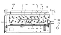
以下、図2から図7を参照して、本実施形態のプリンタ1における現像装置16及びトナーカートリッジ5に係る構成について詳細に説明する。図2は、図1に示す現像装置16に係る構成を示す分解斜視図である。図3は、図2に示す現像装置16に係る構成の分解断面図である。図4は、図2に示す現像装置16に係る構成の断面図である。図5は、図2に示す現像装置16の平面図である。図6は、図1に示すトナーカートリッジ5を底面側から視た斜視図である。図7は、図2に示すトナーカートリッジ5について、蓋体202を取り外した状態で示す平面図である。
Hereinafter, the configuration related to the developing
図2から図4に示すように、本実施形態の現像装置16は、現像ローラ17と、現像室160を有するハウジング162と、現像室160の内部にトナーを補給するトナー補給部20と、トナー搬送部としての第1のトナー攪拌搬送用螺旋羽根19及び第2のトナー攪拌搬送用螺旋羽根18と、を備える。
As shown in FIGS. 2 to 4, the developing
ハウジング162は、ハウジング本体163と、ハウジング本体163に装着される上面壁部材164と、から構成される。現像室160は、現像ローラ17を収容する。ハウジング本体163の現像ローラ17側(図3及び図4の左側)には、上方及び感光体ドラム2側に向けて開放する現像室160が形成されている。現像室160は、その上方に、その内部にトナーを受け入れるためのトナー受入開口220を有する。
The
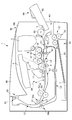
図2から図4に示すように、ハウジング本体163は、底壁165、両側壁166及び連結壁167を有する。連結壁167は、両側壁166の上縁部の間に亘って延びている。ハウジング本体163の底壁165は、並列配置された3つの半円弧状の弧状部165a、165b及び165cを有する。弧状部165aと弧状部165bとの間には、実質的に鉛直上方に延びる直立壁168が設けられている。直立壁168の両側には、直線状経路169a及び169bが形成されている。直線状経路169a及び169bは、その経路の両端部において互いに連通されている。直線状経路169a及び169bにより、無端状のトナー循環経路が形成されている。
As shown in FIGS. 2 to 4, the
図2から図4に示すように、トナー補給部20は、ハウジング162に着脱可能に装着されるトナーカートリッジ5の一部を構成する。トナー補給部20は、現像室160の内部にトナーを補給する。
As shown in FIGS. 2 to 4, the
図2から図4に示すように、第1のトナー攪拌搬送用螺旋羽根19及び第2のトナー攪拌搬送用螺旋羽根18は、現像室160の内部に配設され、現像室160の内部のトナーを現像ローラ17に搬送する。第1のトナー攪拌搬送用螺旋羽根19は、一方の直線状経路169aに配置される。第2のトナー攪拌搬送用螺旋羽根18は、他方の直線状経路169bに配置される。第1のトナー攪拌搬送用螺旋羽根19及び第2のトナー攪拌搬送用螺旋羽根18は、ハウジング本体163の両側壁166間に、回転自在に支持されている。第1のトナー攪拌搬送用螺旋羽根19及び第2のトナー攪拌搬送用螺旋羽根18は、電動モータ170に連結された駆動歯車171に噛み合う受動歯車172、及び受動歯車172に噛み合う受動歯車(図示せず)により、それぞれ図4に示す矢印方向に回転駆動される。
As shown in FIGS. 2 to 4, the first toner agitating / conveying
図5に示すように、第1のトナー攪拌搬送用螺旋羽根19の螺旋方向と、第2のトナー攪拌搬送用螺旋羽根18の螺旋方向とは、逆に設定されている。第1のトナー攪拌搬送用螺旋羽根19が矢印A方向に回転されることによって、直線状経路169aを通して、トナーTNは、矢印A1方向に搬送される。第2のトナー攪拌搬送用螺旋羽根18が矢印B方向に回転されることによって、直線状経路169bを通して、トナーTNは、矢印B1方向に搬送される。
As shown in FIG. 5, the spiral direction of the first toner stirring and conveying
図5に示すように、螺旋羽根18aは、第2のトナー攪拌搬送用螺旋羽根18の搬送方向B1の略中央部分の特定領域Cにおいて、螺旋羽根18aの外径が他の部分の螺旋羽根18の外径に比べて局部的に小さくなるように、構成されている。これにより、特定領域Cにおける搬送能力は局部的に低減されている。
As shown in FIG. 5, the
搬送能力が局部的に低減されている特定領域Cは、トナー受入領域の下流端に位置する。このトナー受入領域は、後述するトナー受入開口220を通して現像室160内にトナーTNが導入される領域である。トナー受入領域の下流側に位置する特定領域Cにおける搬送能力が局部的に低減されていることによって、現像室160内のトナー受入領域において、トナーの滞留(淀み)が生成される。このトナーの滞留により、トナー補給部20から現像室160内へのトナーの導入を自動制御することが可能となる。これによって、第1のトナー攪拌搬送用螺旋羽根19及び第2のトナー攪拌搬送用螺旋羽根18の駆動を制御することなく、現像室160内へのトナーの補給を適切に行うことができる。
The specific area C in which the conveyance capability is locally reduced is located at the downstream end of the toner receiving area. This toner receiving area is an area where the toner TN is introduced into the developing
図2から図4に示すように、ハウジング本体163には、上面壁部材164が装着される。上面壁部材164は、現像室160の上面を覆う上面壁180を有する。上面壁180には、幅方向(図3及び図4において紙面に垂直な方向)に延びる細長い没入域181が形成されている。没入域181には、トナー受入開口220が形成されている。
上面壁部材164は、没入域181に沿って延びる直立壁182を有する。直立壁182には、実質的に水平に突出する一対の支持棒183が、幅方向(図3及び図4において紙面に垂直な方向)に間隔をおいて設けられている。なお、図3及び図4には、一方の支持棒183のみを図示している。
As shown in FIGS. 2 to 4, the
The
上面壁部材164には、現像室シャッター184が装着されている。現像室シャッター184は、平板状のシャッター壁185を有する。シャッター壁185の上面には、一対の突条186が形成されている。突条186の先端には、傾斜面187が形成されている。突条186は、傾斜面187から後方(図3及び図4において左方)に延びる延在部を含んでいる。図2に示すように、シャッター壁185は、その両端から前方に突出する一対の突起188を有する。
A developing
現像室シャッター184は、上面壁部材164の上面壁180の上面に沿って移動自在に装着されている。現像室シャッター184は、その移動により、図3に示す閉位置と、図4に示す開位置とに切り替え可能に構成されている。
上面壁部材164における一対の支持棒183と現像室シャッター184における一対の突条186の延在部との間には、圧縮コイルばね189が介在されている。圧縮コイルばね189は、現像室シャッター184を、図3に示す閉位置に弾性的に付勢する。
The developing
A
以上のような構成により、本実施形態においては、ハウジング本体163に上面壁部材164が装着され、上面壁部材164に現像室シャッター184が装着されている状態において、圧縮コイルばね189の弾性付勢力によって、現像室シャッター184は、図3に示す閉位置に配置される。これにより、現像室シャッター184の一対の突起188の先端がハウジング本体163における直立壁190(図3及び図5)に当接して、現像室シャッター184が図3において閉位置を越えて移動することは阻止される。現像室シャッター184が閉位置に位置されると、図3に示すように、シャッター壁185が上面壁部材164におけるトナー受入開口220を覆う(閉じる)。
With the above configuration, in the present embodiment, the elastic biasing force of the
また、ハウジング本体163にトナーカートリッジ5が装着されると、後述するように、トナーカートリッジ5が現像室シャッター184の傾斜面187に作用して、現像室シャッター184は、圧縮コイルばね189の弾性付勢力に抗して、図4に示す開位置に移動される。現像室シャッター184が開位置に移動されると、シャッター壁185がトナー受入開口220の上方から後退し、トナー受入開口220は露呈される(開けられる)。
When the
図2に示すように、上面壁部材164には、上面壁180の幅方向の一端縁部から上方に突出する直立壁191が形成されている。直立壁191には、上端から下方に延びる案内溝192が形成されている。
上面壁180は、幅方向に延びる収納壁部193を有する。収納壁部193には、ロック手段194が収納されている。図2から図4に示すように、ロック手段194は、幅方向(図2及び図3において紙面に垂直な方向)に細長く延びる主部195と、主部195から上方に突出する操作アーム196と、を有する。
As shown in FIG. 2, the
The
次に、トナーカートリッジ5について説明する。
図2から図4及び図6に示すように、トナーカートリッジ5は、カートリッジケース200を備える。カートリッジケース200は、上面が開口した箱状のケース本体201と、ケース本体201の上面の開口に固定される蓋体202と、から構成される。ケース本体201は、底壁に2つの弧状部203a及び203bを有する。一方の弧状部203aの曲率半径は、他方の弧状部203bの曲率半径よりも大きい。
Next, the
As shown in FIGS. 2 to 4 and 6, the
図6に示すように、曲率半径の小さい弧状部203bには、下方に突出する突出域204が形成されている。突出域204も弧状であり、弧状部203bにおける非突出域(突出していない領域)と同心状である。突出域204の幅方向長さ及び曲率半径は、上面壁部材164の上面壁180に形成されている没入域181の軸方向長さ及び曲率半径に対応している。突出域204は、トナー補給部20を構成する。突出域204の底壁部には、トナー排出開口300が形成されている。
As shown in FIG. 6, the
トナー排出開口300は、トナー受入開口220に対向し且つトナー受入開口220の上方の位置に、トナー補給部20からトナーを排出するための開口である。トナー排出開口300は、弧状の突出域204の軸方向に沿う長辺と円周方向に沿う短辺とを有する長方形状に形成されている。
The
図4に示すように、ハウジング162にトナーカートリッジ5が所定通りに装着されると、上面壁部材164の上面壁180に形成されている没入域181に、ケース本体201の突出域204が載置される。これによって、トナー排出開口300は、トナー受入開口220に対向して、トナー受入開口220の上方に位置される。トナー排出開口300の幅及び長さは、トナー受入開口220の幅及び長さと実質的に同一に又は少し小さく形成されている。
As shown in FIG. 4, when the
図6及び図7に示すように、ケース本体201は、両側壁206を有する。一方の側壁206には、カートリッジケース200内にトナーを充填するための開口207が形成されている。開口207には、トナーの充填後に開口207を閉鎖する閉鎖部材208が固着される。
As shown in FIGS. 6 and 7, the case
図3、図4及び図7に示すように、ケース本体201の両側壁206間には、弧状部203aに沿って延在する第1トナー搬送装置209と、弧状部203bに沿って延在する第2トナー搬送装置210と、が配設されている。第1トナー搬送装置209は、両側壁206の間に回転自在に装着された回転支持軸211と、回転支持軸211に固定された複数個の矩形搬送片212と、から構成されている。回転支持軸211の一端部は、一方の側壁206を貫通してケース本体201の外方へ突出されている。回転支持軸211の突出軸端部に、入力歯車215が固定されている。
As shown in FIGS. 3, 4 and 7, between the
第2トナー搬送装置210は、回転支持軸213及び螺旋羽根214を有する回転螺旋羽根部材から構成されている。回転支持軸213の一端部は、一方の側壁206を貫通して突出されている。回転支持軸213の突出軸端部に、入力歯車216が固定されている。入力歯車216は、第1トナー搬送装置209における回転支持軸211の入力歯車215に噛合されている。
The second
以上の構成により、ハウジング162にトナーカートリッジ5が所定通りに装着されると、入力歯車215は、ハウジング本体163に装着され且つ電動モータ170に連結された駆動歯車171に、噛合される。この状態において、電動モータ170始動されると、現像室160に配設されている第1のトナー攪拌搬送用螺旋羽根19及び第2のトナー攪拌搬送用螺旋羽根18は駆動回転されると共に、トナーカートリッジ5内の第1トナー搬送装置209及び第2トナー搬送装置210は、矢印方向に駆動回転される。これによって、弧状部203a上に存在するトナーTNは、第1トナー搬送装置209により弧状部203b上に搬送される。また、弧状部203b上のトナーTNは、第2トナー搬送装置210によりトナー排出開口300に向けて搬送される。
With the above configuration, when the
図3、図4及び図7に示すように、カートリッジケース200は、弧状部203bの突出域204内に配設されたカートリッジシャッター230を有する。カートリッジシャッター230は、略200度の角度範囲に亘る円弧状のシャッター部材231を有する。シャッター部材231には、トナー通過開口232が形成されている。シャッター部材231のトナー通過開口232は、ケース本体201におけるトナー排出開口300と実質的に同一の大きさ及び形状に形成されている。
As shown in FIGS. 3, 4 and 7, the
図6に示すように、トナーカートリッジ5におけるケース本体201の後壁部には、幅方向に間隔をおいて一対の被ロック片233が備えられている。被ロック片233は、フック形状で、傾斜面234と水平面235と、を有する。
現像装置16のハウジング162に、トナーカートリッジ5を装着する際に、一対の被ロック片233の傾斜面234をハウジング162のロック手段194の傾斜面(図示せず)に作用させることにより、ロック手段194は、弾性付勢力に抗してロック解除位置に移動される。そして、トナーカートリッジ5が所定位置に装着されると、被ロック片233の傾斜面234は、ロック手段194の傾斜面を通過し、また、ロック手段194は、弾性付勢力によりロック位置に復帰する。これによって、トナーカートリッジ5は、ハウジング162の所定位置にロックされて装着される。
As shown in FIG. 6, a pair of locked
When the
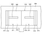
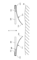
次に、図8から図10を参照して、本実施形態のプリンタ1における現像装置16の特徴的な構成について詳細に説明する。図8は、現像装置16におけるトナー排出開口300付近の拡大平面図である。図9は、現像装置16におけるトナー排出開口300が逆流防止部材310により閉じられた状態の拡大断面図である。図10は、現像装置16におけるトナー排出開口300が開けられた状態の拡大断面図である。
Next, a characteristic configuration of the developing
図8から図10に示すように、現像装置16のトナー排出開口300には、逆流防止部材310が設けられている。逆流防止部材310は、トナーTNの自重により下方、つまり、現像室160の側に撓むことが可能な弾性シート部材から形成される。逆流防止部材310は、トナー補給部20におけるトナーTNの残量が一定量以下に減少したときに、トナー排出開口300を閉じることができ、これにより、現像室160からトナー補給部20へのトナーTNの逆流を防ぐ役目を有する。
As shown in FIGS. 8 to 10, a
逆流防止部材310は、トナー排出開口300の長辺方向において分割された一対のシート部材311,311から形成される。
一対のシート部材311,311は、互いに同一の形状に形成されている。一対のシート部材311,311は、トナー排出開口300の長辺方向の長さの略1/2の長さ及びトナー排出開口300の短辺方向と同一又は少し長い幅を有する。一対のシート部材311,311の長さ方向の一端部は、それぞれ、一対の板部材312,312に、巻き付けた状態で貼り付けられている。一対の板部材312,312は、トナー排出開口300における対向する短辺に沿って配置される。一対のシート部材311,311の長さ方向の一端部は、固定端313,313を構成している。また、一対のシート部材311,311の他端部は、それぞれ、トナーTNの自重により、現像室160の側に撓むことが可能な自由端314,314を構成している。
The
The pair of
図8から図10に示すように、トナー排出開口300には、逆流防止部材310がトナー補給部20の内部に進入することを規制する進入規制部材320,320が設けられている。具体的には、一対の板状の進入規制部材320,320は、一対の板部材312,312の幅方向の中央部からトナー排出開口300の長手方向の中央部に向けて延出されている。一対の進入規制部材320,320は、図9に示すように、一対のシート部材311,311が現像室160側のトナーTNに押されてトナー排出開口300側に撓んだときに、一対のシート部材311,311の上面に当接する。これにより、一対の進入規制部材320,320は、一対のシート部材311,311の自由端314,314がトナー補給部20の内部にまで進入することを規制する。
As shown in FIGS. 8 to 10, the
なお、一対の進入規制部材320,320は、トナー補給部20側から現像室160へトナーTNを補給する際に、トナーTNの流れを阻害することがないように、強度的に及び逆流防止機能に支障のない範囲で可能な限り細い幅で且つ短い延出長さに、形成されている。
It should be noted that the pair of
次に、図1を参照して、第1実施形態のプリンタ1の動作について簡単に説明する。
まず、給紙カセット52に収容された用紙Tに片面印刷を行う場合について説明する。
給紙カセット52に収容された用紙Tは、前送りコロ61及び給紙ローラ対63によって第1搬送路L1に送り出され、その後、第1合流部P1及び第1搬送路L1を介してレジストローラ対80に搬送される。
レジストローラ対80においては、用紙Tのスキュー補正や、トナー画像とのタイミング調整が行われる。
Next, the operation of the
First, a case where single-sided printing is performed on the paper T stored in the
The paper T accommodated in the
In the
レジストローラ対80から排出された用紙Tは、第1搬送路L1を介して感光体ドラム2と転写ローラ8との間の転写ニップNに導入される。そして、用紙Tには、感光体ドラム2と転写ローラ8との間において、トナー画像が転写される。
その後、用紙Tは、感光体ドラム2と転写ローラ8との間から排出され、第2搬送路L2を介して、定着部9における加熱回転体9aと加圧回転体9bとの間の定着ニップに導入される。そして、定着ニップにおいてトナーTNが溶融し、トナーTNが用紙Tに定着される。
The paper T discharged from the
Thereafter, the paper T is discharged from between the
次いで、用紙Tは、第1ローラ対54aにより第3搬送路L3を通して排紙部50に搬送され、第3ローラ対53により排紙部50から排紙集積部M1に排出される。
このようにして、給紙カセット52に収容された用紙Tの片面印刷が完了する。
Next, the paper T is conveyed to the
In this way, single-sided printing of the paper T stored in the
手差しトレイ65に載置された用紙Tに片面印刷を行う場合には、手差しトレイ65に載置された用紙Tは、給紙コロ66によって手差し搬送路Laに送り出され、その後、第1合流部P1及び第1搬送路L1を介して、レジストローラ対80に搬送される。それ以降の動作は、前述した、給紙カセット52に収容された用紙Tの片面印刷の動作と同様であり、説明を省略する。
When single-sided printing is performed on the paper T placed on the
次に、両面印刷を行う場合のプリンタ1の動作について説明する。
片面印刷の場合には、前述した通り、片面印刷がされた用紙Tが、排紙部50から排紙集積部M1に排出されて印刷動作が完了する。
これに対し、両面印刷を行う場合には、片面印刷された用紙Tが、戻し搬送路Lbを介して、片面印刷時とは表裏反転して、レジストローラ対80に再度搬送されることにより、用紙Tに両面印刷が施される。
Next, the operation of the
In the case of single-sided printing, as described above, the paper T on which single-sided printing has been performed is discharged from the
On the other hand, when performing double-sided printing, the paper T that has been printed on one side is reversed from the front and back of the single-sided printing via the return conveyance path Lb, and is conveyed again to the
詳述すると、片面印刷がされた用紙Tが第3ローラ対53により排紙部50から排出されるまでは、前述した片面印刷の動作と同様である。而して、両面印刷の場合には、片面印刷がされた用紙Tが第3ローラ対53により保持されている状態において、第3ローラ対53の回転を停止させ、逆方向に回転させる。このように第3ローラ対53を逆方向に回転させると、第3ローラ対53に保持されている用紙Tは、第3搬送路L3を逆方向(排紙部50から第1分岐部Q1に向かう方向)に搬送される。
More specifically, the operation is the same as the above-described single-sided printing operation until the paper T on which single-sided printing has been performed is discharged from the
前述したように、用紙Tが、第3搬送路L3を逆方向に搬送されると、第2ローラ対54bに導入される。そして、用紙Tは、戻し搬送路Lb及び第2合流部P2を介して、第1搬送路L1に合流する。ここで、用紙Tは、片面印刷時とは表裏反転している。
As described above, when the paper T is transported in the reverse direction along the third transport path L3, it is introduced into the
更に、用紙Tは、レジストローラ対80により前記補正又は前記調整が行われ、第1搬送路L1を介して、感光体ドラム2と転写ローラ8との間に導入される。用紙Tは、戻し搬送路Lbを経由することにより、非印刷面が感光体ドラム2に対向するので、非印刷面にトナー画像が転写され、その結果、両面印刷が施される。
Further, the paper T is corrected or adjusted by the
次に、本実施形態の現像装置16において、トナーカートリッジ5の一部も構成するトナー補給部20から、現像室160内へトナーTNが補給される動作について説明する。
トナーカートリッジ5の内部に十分な量のトナーTNが収容され、トナー補給部20におけるトナーTNの残量が一定量に保たれている場合には、トナー補給部20のトナーTNの自重により、逆流防止部材310を形成する一対のシート部材311、311は、図11に示すように、現像室160側に撓んで、トナー排出開口300を開放する。
Next, in the developing
When a sufficient amount of toner TN is accommodated in the
ここで、一対のシート部材311,311が可撓性を有する弾性シート部材から形成されているので、一対のシート部材311,311は、自重による下向きの押し込み力Fを受けた際に、自由端314,314側ほど大きく下方へ撓んで変形する。これによって、トナー排出開口300の開口面積を大きく確保することが可能となり、トナー補給部20から現像室160へのトナーの補給をスムーズに且つ効率的に行なうことができる。
Here, since the pair of
このようなトナーの補給の繰り返しにより、トナーカートリッジ5の内部のトナーTNが消費されて、トナー補給部20にトナーの残量が一定量以下に減少すると、トナーによる下向きの押し込み力Fが下がる。一方、現像室160内のトナーTNは、搬送能力が局部的に低減されている特定領域Cにおいて、滞留しやすい(淀みやすい)。その結果、図12に示すように、特定領域Cに滞留しているトナーTNは、矢印方向Uに逆流して次第に盛り上がり、一対のシート部材311,311を押し上げる。
When the toner TN inside the
そして、図13に示すように、現像室160側のトナーTNの最上面は、トナー排出開口300と略同一の高さレベルまで盛り上がる。これに伴って、一対のシート部材311,311は、上方に押し上げられ、進入規制部材320,320の下面に当接して、トナー排出開口300を閉じる。これによって、現像室160からトナー補給部20へのトナーTNの逆流は、抑制される。また、一対のシート部材311,311の自由端314,314がトナー補給部20の内部に進入することが規制される。
As shown in FIG. 13, the uppermost surface of the toner TN on the developing
また、トナーカートリッジ5の交換等により、トナー補給部20に一定量以上のトナーTNが供給されると、逆流防止部材310を形成する一対のシート部材311、311は、図11に示すように、現像室160側に撓んでトナー排出開口300を開放し、所定のトナーの補給を行なうことができる。
Further, when a predetermined amount or more of toner TN is supplied to the
本実施形態の現像装置16によれば、例えば、次のような効果が奏される。
本実施形態の現像装置16においては、トナー補給部20からトナーを排出するためのトナー排出開口300に、トナーTNの自重により現像室160の側に撓むことが可能なシート部材から形成される逆流防止部材310であって、トナー補給部20におけるトナーの残量が一定量以下に減少したときに、トナー排出開口300を閉じて現像室160からトナー補給部20へのトナーの逆流を防ぐ逆流防止部材310が設けられている。
According to the developing
In the developing
そのため、本実施形態においては、トナー補給部20におけるトナーの残量が一定量以下に減少し、トナー補給部20から現像室160内へのトナーの補給圧力(押込み力)が下がったときに、トナー排出開口300を逆流防止部材310により閉じることができる。これによって、現像室160の内部のトナー受入領域からトナーTNがトナー排出開口300を通じてトナー補給部20へ逆流することを防止することができる。従って、トナー補給部20におけるトナー残量の予測精度を向上でき、多くの量の未使用のトナーを残したままで、トナーカートリッジ5(トナー補給部20)を交換するといったトナーロスを十分に抑制できる。
Therefore, in the present embodiment, when the remaining amount of toner in the
また、本実施形態の現像装置16においては、逆流防止部材310は、一対のシート部材311,311から形成され、一対のシート部材311,311の一端部は、それぞれ、トナー排出開口300における対向する辺に固定される固定端313,313を構成し、一対のシート部材311,311の他端部は、それぞれトナーの自重により現像室160の側に撓むことが可能な自由端314,314を構成している。
Further, in the developing
そのため、トナー補給部20から現像室160へのトナーの補給時には、逆流防止部材310の一対のシート部材311,311が両開き式に開放すると共に、両開きされた一対のシート部材311,311は、それらの自由端314,314側ほど大きく撓む。そのため、シート部材311,311におけるトナー滑り面(トナーが滑る面)の傾斜角度を非常に大きく取ることができる。これによって、トナー排出開口300の開口面積を十分に大きく確保することが可能である。従って、所定のトナー補給を、スムーズに且つ短時間で効率よく行なうことができる。
Therefore, when toner is supplied from the
また、本実施形態の現像装置16においては、トナー排出開口300に、逆流防止部材310の一対のシート部材311,311がトナー補給部20の内部に進入することを規制する進入規制部材320,320が設けられている。
そのため、現像室160側から逆流してくるトナーTNにより押し上げられるシート部材311,311の自由端314,314が、トナー補給部20の内部に進入することを、規制することができる。これによって、トナーTNの逆流防止機能を確実に達成できると共に、シート部材311,311の自由端314,314がトナー補給部20内に進入して、例えば、トナーカートリッジ5の交換時に閉じられるカートリッジシャッター230の動作を阻害したり、トナー補給部20の内部のどこかに引っ掛かり、元の状態に戻らなくなったりする等のトラブルの発生を抑制することができる。
Further, in the developing
Therefore, the free ends 314 and 314 of the
以上、本発明の好適な実施形態について説明したが、本発明は、前述した実施形態に限定されることなく、種々の形態で実施することができる。
例えば、上記の実施形態では、一対のシート部材311,311の一端部を板部材312,312に巻き付けた状態に貼り付けて固定することにより、固定端313,313を構成しているが、これに制限されない。例えば、一対のシート部材311,311の一端部を板部材312,312の下面に直接貼り付けて固定することにより、固定端313,313を構成してもよい。
As mentioned above, although preferred embodiment of this invention was described, this invention can be implemented with a various form, without being limited to embodiment mentioned above.
For example, in the above embodiment, the fixed ends 313 and 313 are configured by sticking and fixing one end of the pair of
また、本発明の画像形成装置の種類は、特に限定がなく、コピー機、プリンタ、ファクシミリ、又はこれらの複合機などであってもよい。
さらに、シート状の被転写材は、用紙に制限されず、例えば、フィルムシートであってもよい。
The type of the image forming apparatus of the present invention is not particularly limited, and may be a copier, a printer, a facsimile, or a complex machine thereof.
Further, the sheet-shaped transfer material is not limited to paper, and may be a film sheet, for example.
次に、本発明の実施例について説明する。ただし、本発明は、以下の実施例のみに限定されるものでない。
試験に供した実施例及び比較例1,2における共通の条件は、次の通りである。
現像室内のトナーの量:80g
トナーカートリッジ内のトナーの量:200g
印字率:4%
トナーの消費量:40mg/page
トナー受入開口の大きさ:250mm×150mm
Next, examples of the present invention will be described. However, the present invention is not limited to the following examples.
Common conditions in the examples and comparative examples 1 and 2 subjected to the test are as follows.
Amount of toner in developing chamber: 80 g
Amount of toner in toner cartridge: 200 g
Printing rate: 4%
Toner consumption: 40 mg / page
Toner receiving opening size: 250 mm × 150 mm
上記の共通条件下において、実施例1では、逆流防止部材として、次の条件の一対のシート部材を用いた。
厚み:75μm
長さ:200mm
自由端長:125mm
幅:150mm
実施例2では、逆流防止部材として、次の条件の一対のシート部材を用いた。
厚み:50μm
長さ:200mm
自由端長:125mm
幅:150mm
比較例1では、逆流防止部材を用いていない。
比較例2では、剛性板部材からなる逆流防止部材を片開き式に装着した。
Under the above common conditions, in Example 1, a pair of sheet members having the following conditions was used as the backflow preventing member.
Thickness: 75μm
Length: 200mm
Free end length: 125mm
Width: 150mm
In Example 2, a pair of sheet members having the following conditions was used as the backflow preventing member.
Thickness: 50 μm
Length: 200mm
Free end length: 125mm
Width: 150mm
In Comparative Example 1, no backflow prevention member is used.
In Comparative Example 2, the backflow prevention member made of a rigid plate member was attached in a single-open manner.
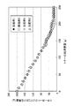
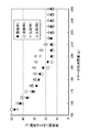
上記各条件下において、原稿を4%の印字率で印字した時のトナーの消費量(g)とトナーカートリッジの内部におけるトナーの残量(g)との関係を測定する試験を行った。 Under each of the above conditions, a test was performed to measure the relationship between the toner consumption (g) when the original was printed at a printing rate of 4% and the remaining amount of toner (g) inside the toner cartridge.
試験の結果は、図14及び図15に示す通りであった。
実施例(実施例1,2)の場合には、トナーカートリッジ内のトナーの残量が減少しても、現像室内からの逆流が発生しないため、減少の程度は緩やかになるものの、トナーカートリッジ内のトナーの量が速やかに減少した。
比較例1,2の場合には、トナーカートリッジ内のトナーの残量が減少すると、現像室内からの逆流が発生し、そのため、トナーカートリッジ内のトナーの量が安定しないままで、現像室内のトナー量が減少した。そして、現像室内のトナーの滞留がなくなってから、トナーカートリッジ内のトナーの量が安定した。
The results of the test were as shown in FIGS.
In the case of the embodiments (Embodiments 1 and 2), even if the remaining amount of toner in the toner cartridge is reduced, no backflow occurs from the developing chamber. The amount of toner decreased rapidly.
In the case of Comparative Examples 1 and 2, when the remaining amount of toner in the toner cartridge decreases, backflow from the developing chamber occurs, and therefore the amount of toner in the toner cartridge remains unstable and the toner in the developing chamber remains unstabilized. The amount decreased. After the toner stays in the developing chamber, the amount of toner in the toner cartridge is stabilized.
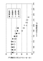
また、トナーカートリッジ内のトナーの残量が安定するまでの現像室内のトナーの残量の変化を測定したところ、図16に示すような結果が得られた。
実施例(実施例1,2)の場合には、トナーの残量が安定するまでの時間が短いため、現像室内のトナーの残量は、10gの減少に抑制されていた。
比較例1,2の場合には、トナーの残量が安定するまでの時間が長いため、現像室内のトナーの残量は、30gも減少し、その結果、トナーの供給不足による白抜け画像や、トナーカートリッジの交換後におけるトナー補給時間の短縮や補給カブリの発生に不利であった。
Further, when the change in the remaining amount of toner in the developing chamber until the remaining amount of toner in the toner cartridge is stabilized, the result as shown in FIG. 16 is obtained.
In the case of the examples (Examples 1 and 2), since the time until the remaining amount of toner is stabilized is short, the remaining amount of toner in the developing chamber is suppressed to a decrease of 10 g.
In Comparative Examples 1 and 2, since the time until the remaining amount of toner becomes stable is long, the remaining amount of toner in the developing chamber is reduced by 30 g. This is disadvantageous in shortening the toner replenishment time after replacement of the toner cartridge and generating replenishment fog.
1……プリンタ(画像形成装置)、2……感光体ドラム(像担持体)、5……トナーカートリッジ、6……トナー補給部、8……転写ローラ(転写部)、9……定着部、10……帯電部、16……現像装置、17……現像ローラ(トナー担持体)、18,19……トナー攪拌搬送用螺旋羽根(トナー搬送部)、160……現像室、162……ハウジング、220……トナー受入開口、300……トナー排出開口、310……逆流防止部材、311……シート部材、313……固定端、314……自由端、330……進入規制部材、T……用紙(被転写材)、TN……トナー
DESCRIPTION OF
Claims (4)
前記トナー担持体を収容する現像室を有するハウジングと、
前記現像室の内部にトナーを補給するトナー補給部と、
前記現像室の内部に配設され、前記現像室の内部のトナーを前記トナー担持体に搬送するトナー搬送部と、を備える現像装置であって、
前記現像室は、その上方に、その内部にトナーを受け入れるためのトナー受入開口を有し、
前記トナー補給部は、前記トナー受入開口に対向し且つ該トナー受入開口の上方の位置に、前記トナー補給部からトナーを排出するためのトナー排出開口を有し、
前記トナー排出開口に、トナーの自重により前記現像室の側に撓むことが可能なシート部材から形成される逆流防止部材であって、前記トナー補給部におけるトナーの残量が一定量以下に減少したときに、前記トナー排出開口を閉じて前記現像室から前記トナー補給部へのトナーの逆流を防ぐ逆流防止部材が設けられており、
前記逆流防止部材は、一対の前記シート部材から形成され、
前記一対のシート部材の一端部は、それぞれ、前記トナー排出開口における対向する辺に固定される固定端を構成し、前記一対のシート部材の他端部は、それぞれトナーの自重により前記現像室の側に撓むことが可能な自由端を構成する
現像装置。 A toner carrier for carrying toner;
A housing having a developing chamber for accommodating the toner carrier;
A toner replenishing section for replenishing toner inside the developing chamber;
A developing device provided in the developing chamber, and a toner transport unit that transports the toner in the developing chamber to the toner carrier,
The developing chamber has a toner receiving opening for receiving toner inside the developing chamber,
The toner replenishing portion has a toner discharge opening for discharging the toner from the toner replenishing portion at a position facing the toner receiving opening and above the toner receiving opening;
A backflow prevention member formed at the toner discharge opening from a sheet member capable of being bent toward the developing chamber by the weight of the toner, and the remaining amount of toner in the toner replenishing portion is reduced to a predetermined amount or less. A backflow prevention member that closes the toner discharge opening and prevents the backflow of toner from the developing chamber to the toner replenishing portion is provided,
The backflow prevention member is formed from a pair of the sheet members,
One end of each of the pair of sheet members constitutes a fixed end that is fixed to an opposite side of the toner discharge opening, and the other end of each of the pair of sheet members is in the developing chamber due to its own weight. The developing device which comprises the free end which can bend to the side.
請求項1に記載の現像装置。 The developing device according to claim 1, wherein the toner replenishing portion constitutes a part of a toner cartridge that is detachably attached to the housing.
請求項1又は2に記載の現像装置。 The developing device according to claim 1, wherein the toner discharge opening is provided with an entry restricting member that restricts the backflow preventing member from entering the inside of the toner replenishing portion.
表面に静電潜像が形成されると共に、前記現像装置の前記トナー担持体からトナーの供給を受けて静電潜像にトナー画像が形成される1又は複数の像担持体と、
前記像担持体に形成されたトナー画像を直接的又は間接的にシート状の被転写材に転写する転写部と、
転写されたトナー画像を前記シート状の被転写材に定着する定着部と、を備える
画像形成装置。 A developing device according to any one of claims 1 to 3,
One or more image carriers on which an electrostatic latent image is formed, and a toner image is formed on the electrostatic latent image upon receipt of toner from the toner carrier of the developing device;
A transfer unit that directly or indirectly transfers the toner image formed on the image carrier to a sheet-like transfer material;
An image forming apparatus comprising: a fixing unit that fixes the transferred toner image to the sheet-like transfer material.
Priority Applications (1)
| Application Number | Priority Date | Filing Date | Title |
|---|---|---|---|
| JP2011050831A JP5463312B2 (en) | 2011-03-08 | 2011-03-08 | Developing device and image forming apparatus |
Applications Claiming Priority (1)
| Application Number | Priority Date | Filing Date | Title |
|---|---|---|---|
| JP2011050831A JP5463312B2 (en) | 2011-03-08 | 2011-03-08 | Developing device and image forming apparatus |
Publications (2)
| Publication Number | Publication Date |
|---|---|
| JP2012189643A true JP2012189643A (en) | 2012-10-04 |
| JP5463312B2 JP5463312B2 (en) | 2014-04-09 |
Family
ID=47082909
Family Applications (1)
| Application Number | Title | Priority Date | Filing Date |
|---|---|---|---|
| JP2011050831A Expired - Fee Related JP5463312B2 (en) | 2011-03-08 | 2011-03-08 | Developing device and image forming apparatus |
Country Status (1)
| Country | Link |
|---|---|
| JP (1) | JP5463312B2 (en) |
Cited By (1)
| Publication number | Priority date | Publication date | Assignee | Title |
|---|---|---|---|---|
| JP2016053710A (en) * | 2014-09-02 | 2016-04-14 | キヤノンファインテック株式会社 | Developing device and image forming apparatus |
Citations (4)
| Publication number | Priority date | Publication date | Assignee | Title |
|---|---|---|---|---|
| JPH01250975A (en) * | 1988-03-31 | 1989-10-05 | Canon Inc | developer |
| JP2000310905A (en) * | 1999-04-28 | 2000-11-07 | Sharp Corp | Developing cartridge |
| JP2006058371A (en) * | 2004-08-17 | 2006-03-02 | Ricoh Co Ltd | Developing device, image forming unit including the same, and image forming apparatus including the same |
| US20090067887A1 (en) * | 2007-09-12 | 2009-03-12 | Tetsumaru Fujita | Image forming apparatus, image forming method, and developing device |
-
2011
- 2011-03-08 JP JP2011050831A patent/JP5463312B2/en not_active Expired - Fee Related
Patent Citations (4)
| Publication number | Priority date | Publication date | Assignee | Title |
|---|---|---|---|---|
| JPH01250975A (en) * | 1988-03-31 | 1989-10-05 | Canon Inc | developer |
| JP2000310905A (en) * | 1999-04-28 | 2000-11-07 | Sharp Corp | Developing cartridge |
| JP2006058371A (en) * | 2004-08-17 | 2006-03-02 | Ricoh Co Ltd | Developing device, image forming unit including the same, and image forming apparatus including the same |
| US20090067887A1 (en) * | 2007-09-12 | 2009-03-12 | Tetsumaru Fujita | Image forming apparatus, image forming method, and developing device |
Cited By (1)
| Publication number | Priority date | Publication date | Assignee | Title |
|---|---|---|---|---|
| JP2016053710A (en) * | 2014-09-02 | 2016-04-14 | キヤノンファインテック株式会社 | Developing device and image forming apparatus |
Also Published As
| Publication number | Publication date |
|---|---|
| JP5463312B2 (en) | 2014-04-09 |
Similar Documents
| Publication | Publication Date | Title |
|---|---|---|
| JP4429856B2 (en) | Recording medium conveying apparatus and image forming apparatus | |
| JP5804652B2 (en) | Image forming apparatus | |
| KR101457760B1 (en) | Developer container and image forming device equipped with the same | |
| JP5789552B2 (en) | Image forming apparatus | |
| JP5942475B2 (en) | Development device | |
| US9511966B2 (en) | Sheet conveying device and image forming apparatus including the same | |
| JP5883832B2 (en) | Image forming apparatus | |
| JP5272468B2 (en) | Spring mounting structure and image forming apparatus | |
| JP5086460B2 (en) | Image forming apparatus | |
| JP4811513B2 (en) | Development unit | |
| JP2004299817A (en) | Image forming apparatus main body and image forming apparatus provided with the same | |
| JP5062192B2 (en) | Image forming apparatus | |
| JP6216123B2 (en) | Image forming apparatus | |
| JP5463312B2 (en) | Developing device and image forming apparatus | |
| JP5212505B2 (en) | Image forming apparatus | |
| JP2012242736A (en) | Sheet processing apparatus | |
| JP5162620B2 (en) | Member moving mechanism and image forming apparatus | |
| JP2009046293A (en) | Paper feeding cassette and image forming device equipped with it | |
| JP5309256B2 (en) | Image forming apparatus and toner container | |
| JP4956280B2 (en) | Paper feeding cassette and image forming apparatus | |
| JP5352724B2 (en) | Toner container | |
| JP2011137981A (en) | Toner conveying device and image forming apparatus | |
| JP4831249B2 (en) | Image forming apparatus | |
| JP2011153008A (en) | Image forming device | |
| JP4467456B2 (en) | Paper transport mechanism of image forming apparatus |
Legal Events
| Date | Code | Title | Description |
|---|---|---|---|
| RD04 | Notification of resignation of power of attorney |
Free format text: JAPANESE INTERMEDIATE CODE: A7424 Effective date: 20120803 |
|
| A621 | Written request for application examination |
Free format text: JAPANESE INTERMEDIATE CODE: A621 Effective date: 20130222 |
|
| A977 | Report on retrieval |
Free format text: JAPANESE INTERMEDIATE CODE: A971007 Effective date: 20131216 |
|
| TRDD | Decision of grant or rejection written | ||
| A01 | Written decision to grant a patent or to grant a registration (utility model) |
Free format text: JAPANESE INTERMEDIATE CODE: A01 Effective date: 20131224 |
|
| A977 | Report on retrieval |
Free format text: JAPANESE INTERMEDIATE CODE: A971007 Effective date: 20140116 |
|
| A61 | First payment of annual fees (during grant procedure) |
Free format text: JAPANESE INTERMEDIATE CODE: A61 Effective date: 20140120 |
|
| R150 | Certificate of patent or registration of utility model |
Ref document number: 5463312 Country of ref document: JP Free format text: JAPANESE INTERMEDIATE CODE: R150 Free format text: JAPANESE INTERMEDIATE CODE: R150 |
|
| LAPS | Cancellation because of no payment of annual fees |