JP2012190274A - Modelling device and method for the same - Google Patents
Modelling device and method for the same Download PDFInfo
- Publication number
- JP2012190274A JP2012190274A JP2011053436A JP2011053436A JP2012190274A JP 2012190274 A JP2012190274 A JP 2012190274A JP 2011053436 A JP2011053436 A JP 2011053436A JP 2011053436 A JP2011053436 A JP 2011053436A JP 2012190274 A JP2012190274 A JP 2012190274A
- Authority
- JP
- Japan
- Prior art keywords
- model
- input
- value
- constraint condition
- modeling
- Prior art date
- Legal status (The legal status is an assumption and is not a legal conclusion. Google has not performed a legal analysis and makes no representation as to the accuracy of the status listed.)
- Granted
Links
- 238000000034 method Methods 0.000 title claims abstract description 86
- 238000011156 evaluation Methods 0.000 claims abstract description 135
- 238000004364 calculation method Methods 0.000 claims description 68
- 239000002245 particle Substances 0.000 claims description 61
- 238000005457 optimization Methods 0.000 claims description 58
- 238000012821 model calculation Methods 0.000 claims description 11
- 238000003860 storage Methods 0.000 abstract description 87
- 230000006870 function Effects 0.000 description 69
- 230000004044 response Effects 0.000 description 51
- 239000000428 dust Substances 0.000 description 17
- 238000002485 combustion reaction Methods 0.000 description 10
- 230000008859 change Effects 0.000 description 9
- 238000004891 communication Methods 0.000 description 9
- 239000002699 waste material Substances 0.000 description 9
- 238000010586 diagram Methods 0.000 description 7
- 230000008569 process Effects 0.000 description 6
- 238000012546 transfer Methods 0.000 description 6
- 238000005094 computer simulation Methods 0.000 description 5
- 238000005293 physical law Methods 0.000 description 5
- 238000012545 processing Methods 0.000 description 5
- 239000000126 substance Substances 0.000 description 5
- 238000007796 conventional method Methods 0.000 description 4
- 238000013500 data storage Methods 0.000 description 4
- 239000011159 matrix material Substances 0.000 description 4
- 238000005070 sampling Methods 0.000 description 4
- 238000010276 construction Methods 0.000 description 3
- 238000013461 design Methods 0.000 description 3
- 238000002474 experimental method Methods 0.000 description 3
- 230000015654 memory Effects 0.000 description 3
- 238000004088 simulation Methods 0.000 description 3
- 230000006399 behavior Effects 0.000 description 2
- 230000000052 comparative effect Effects 0.000 description 2
- 238000001914 filtration Methods 0.000 description 2
- 238000012986 modification Methods 0.000 description 2
- 230000004048 modification Effects 0.000 description 2
- 238000007781 pre-processing Methods 0.000 description 2
- 238000005096 rolling process Methods 0.000 description 2
- 238000012360 testing method Methods 0.000 description 2
- UGFAIRIUMAVXCW-UHFFFAOYSA-N Carbon monoxide Chemical compound [O+]#[C-] UGFAIRIUMAVXCW-UHFFFAOYSA-N 0.000 description 1
- 230000002159 abnormal effect Effects 0.000 description 1
- 238000004458 analytical method Methods 0.000 description 1
- QVGXLLKOCUKJST-UHFFFAOYSA-N atomic oxygen Chemical compound [O] QVGXLLKOCUKJST-UHFFFAOYSA-N 0.000 description 1
- 229910002091 carbon monoxide Inorganic materials 0.000 description 1
- 239000003054 catalyst Substances 0.000 description 1
- 238000013480 data collection Methods 0.000 description 1
- 238000011161 development Methods 0.000 description 1
- 238000002309 gasification Methods 0.000 description 1
- 235000000334 grey box Nutrition 0.000 description 1
- 244000085685 grey box Species 0.000 description 1
- 238000010438 heat treatment Methods 0.000 description 1
- 230000010365 information processing Effects 0.000 description 1
- 230000010354 integration Effects 0.000 description 1
- 238000004519 manufacturing process Methods 0.000 description 1
- 238000013178 mathematical model Methods 0.000 description 1
- 230000007246 mechanism Effects 0.000 description 1
- 238000002844 melting Methods 0.000 description 1
- 230000008018 melting Effects 0.000 description 1
- 229910052760 oxygen Inorganic materials 0.000 description 1
- 239000001301 oxygen Substances 0.000 description 1
- 230000000737 periodic effect Effects 0.000 description 1
- 230000002093 peripheral effect Effects 0.000 description 1
- 230000003252 repetitive effect Effects 0.000 description 1
- 239000004576 sand Substances 0.000 description 1
- 229920006395 saturated elastomer Polymers 0.000 description 1
- 230000001502 supplementing effect Effects 0.000 description 1
- 230000036962 time dependent Effects 0.000 description 1
- 230000007704 transition Effects 0.000 description 1
- 230000017105 transposition Effects 0.000 description 1
- 230000003936 working memory Effects 0.000 description 1
Images


Landscapes
- Feedback Control In General (AREA)
Abstract
Description
本発明は、システムのモデルを作成するモデリング装置およびモデリング方法に関し、特に、先験的知識による先験的情報を利用することができるモデリング装置およびモデリング方法に関する。 The present invention relates to a modeling apparatus and a modeling method for creating a model of a system, and more particularly to a modeling apparatus and a modeling method that can use a priori information based on a priori knowledge.
近年の計算機(コンピュータ)の発展に伴い、システムの制御系の設計には、コンピュータを用いたシミュレーションが活用されている。実世界のシステムをコンピュータ上の仮想世界に取り入れるためには、実世界のシステムをコンピュータで取り扱い可能な形式で表現した、実世界と仮想世界とを結び付けるモデルで実世界のシステムを記述する必要がある。このモデルは、通常、微分方程式、差分方程式、伝達関数、状態方程式および論理式等の数学モデルである。シミュレーション結果が実世界のシステムを正確に表すものであるか否かは、このモデルの良し悪し(モデルの精度)によって決定され、このモデルを構築する作業は、モデリングと呼ばれる。 With the development of computers (computers) in recent years, computer-based simulation is used for designing a system control system. In order to incorporate a real-world system into a virtual world on a computer, it is necessary to describe the real-world system using a model that connects the real world and the virtual world in a form that can be handled by a computer. is there. This model is usually a mathematical model such as a differential equation, a difference equation, a transfer function, a state equation and a logical formula. Whether or not the simulation result accurately represents a real-world system is determined by the quality of the model (model accuracy), and the work of building this model is called modeling.
モデリング方法は、ホワイトボックスモデリングとブラックボックスモデリングとに大別され、さらに、これらホワイトボックスモデリングとブラックボックスモデリングとを折衷したグレーボックスモデリングがある。 The modeling methods are roughly classified into white box modeling and black box modeling, and there is a gray box modeling that compromises these white box modeling and black box modeling.
このホワイトボックスモデリングは、いわゆる第1原理に基づくモデリングであり、モデリングの対象であるシステムを支配する物理法則や化学法則等の自然法則(第1原理)と物理化学的な諸量とに基づいてモデリングを行う方法であり、対象が物理システムの場合には物理モデリングと呼ばれる。この方法は、システム(対象)が比較的小規模でこのシステムに作用している物理法則等の自然法則がよく分かっている場合に有効であるが、一般にシステムの大規模化あるいは複雑化に従ってその適用が難しくなる。なお、大規模システムの場合に、この大規模システムを小規模なサブシステムに分割し、各サブシステムに本方法を適用してモデリングを行い、それらを統合することによって大規模システムに本方法を適用することもある。 This white box modeling is based on the so-called first principle, and is based on natural laws (first principles) such as physical laws and chemical laws governing the system to be modeled, and various physicochemical quantities. This is a method of modeling, and is called physical modeling when the target is a physical system. This method is effective when the system (target) is relatively small and natural laws such as the physical laws acting on this system are well understood. It becomes difficult to apply. In the case of a large-scale system, this large-scale system is divided into small subsystems, this method is applied to each subsystem, modeling is performed, and these are integrated into a large-scale system. May apply.
ブラックボックスモデリングは、物理法則や化学法則等の自然法則や先験的知識を用いることなく、システムをブラックボックスと見なして、システム(対象)で観測された有限個の入出力データから、所定の目的(仕様)に応じたモデルを構築する方法であり、制御工学の分野では、システム同定と呼ばれる。システムが比較的大規模あるいは複雑であり、物理法則等の自然法則のみによってシステムの動特性が記述することができない場合に有効であるが、同じ入出力データが与えられても、モデリングの目的(仕様)やモデリングを行う技術者によって得られるモデルが異なる場合があり、主観的要素が入り込む余地がある。 Black box modeling considers a system as a black box without using natural laws such as physical laws and chemical laws, or a priori knowledge. This is a method of building a model according to the purpose (specification), and is called system identification in the field of control engineering. This is effective when the system is relatively large or complex, and the dynamic characteristics of the system cannot be described only by natural laws such as physical laws. Even if the same input / output data is given, the purpose of modeling ( Specifications) and models obtained by modeling engineers may differ, and there is room for subjective factors.
グレーボックスモデリングは、これらホワイトボックスモデリングとブラックボックスモデリングとの中間に位置づけられる方法であり、例えば、モデルの構築に、観測された入出力データに加えて、物理法則等の自然法則が部分的に利用される。 Gray box modeling is a method that is positioned between white box modeling and black box modeling.For example, in addition to observed input / output data, natural laws such as physical laws are partially used in model construction. Used.
モデリングの対象となるシステムには、例えば、多関節ロボット(マニピュレータ)等のようにシステムの基本的な挙動が運動方程式によって記述することができ、ホワイトボックスモデリングを採用可能なシステムもあるが、一般的には、例えば熱処理や化学処理等の伴う燃焼炉や化学プラント等のように、その動特性を自然法則から導出し難いケースが多く、システムのモデリング(システムのモデル化)には、ブラックボックスモデルイングやグレーボックスモデルイングを用いることが多い。 Some systems that can be modeled can describe the basic behavior of the system in terms of equations of motion, such as an articulated robot (manipulator). In many cases, such as combustion furnaces and chemical plants with heat treatment and chemical treatment, it is difficult to derive the dynamic characteristics from the laws of nature, and black box is used for system modeling (system modeling). Modeling and gray box modeling are often used.
このブラックボックスモデリングやグレーボックするモデリングでは、入出力データを用いることによってモデルが構築されるため、モデルの良し悪しがその入出力データに依存し、高精度なモデリングを可能とする質および量ともに充分な入出力データが事前に得られることが望ましい。しかしながら、現実には、実際のシステムに入力可能な波形や大きさ(レベル)等が限られていたり、これら入出力データを採取する実験機会が限られていたり等するために、必ずしも前記質および量ともに充分な入出力データが得られない場合が多い。さらに、実際のシステムから採取された入出力データには、ノイズも存在し、このノイズが場合によっては、モデリングに無視できないほどの大きな悪影響を及ぼすこともあり得る。また、システムによっては、例えば、入力信号に対する持続励振性(persistently exciting、PE性)等のように、モデルが満たすべき条件が存在する場合もある。このような場合では、例えば入出力データの採取作業、入出力データのうちモデリングに用いる範囲の選定、サンプリング間隔の選定、異常値の除去(フィルタリング)等の前処理、モデルの次数の選定等の、高精度なモデルを構築するためのモデリング作業は、試行錯誤の繰り返しになることが多く、モデルの完成に多大な手間と比較的長い時間が必要とされてしまう。そこで、システムのモデル化に先験的知識を補うことによって、モデルを高精度化する技術が例えば非特許文献1や特許文献1に開示されている。
In this black box modeling or gray-bock modeling, the model is constructed by using input / output data, so the quality of the model depends on the input / output data, and both the quality and quantity that enable highly accurate modeling It is desirable that sufficient input / output data is obtained in advance. However, in reality, the waveform and size (level) that can be input to an actual system are limited, and the experimental opportunities to collect these input / output data are limited. In many cases, sufficient input / output data cannot be obtained. Furthermore, noise is also present in input / output data collected from an actual system, and in some cases, this noise can have a significant negative impact on the modeling. Also, depending on the system, there may be a condition that the model should satisfy, such as persistently exciting (PE property) for the input signal. In such a case, for example, input / output data collection work, selection of input / output data range for modeling, selection of sampling interval, preprocessing such as removal of abnormal values (filtering), selection of model order, etc. The modeling work for constructing a highly accurate model often involves repeated trial and error, and much time and a relatively long time are required to complete the model. Thus, for example,
この非特許文献1には、モデルの定常ゲインの符号および安定性に関する先験的情報を制約条件としてモデリングする技術が開示されている。しかしながら、システムには、前記定常ゲインおよび安定性だけではなく、一次遅れ系の場合でも、定常ゲインの範囲や時定数の範囲等も制約されていることが多い(先験的知識となっていることも多い)。このため、非特許文献1に開示の技術では、これらを満たすモデルが得られるとは限らない。
This
また、特許文献1に開示のシステム同定方法は、システムの先験的知識の組込みによって前記システムの初期パラメトリックモデルを改善する方法であって、まず、第1に制約条件なしの最適化により、システムのテストデータ情報のみに基づいて初期化モデルが生成され、第2に先験的知識の制約の存在下において、この初期化モデルが最適化される。すなわち、前記システムの前記初期パラメトリックモデルは、複数の入力信号と複数の出力信号(システムのテストデータ情報)の解析に基づいた複数のパラメータを含むモデルであり、システム同定では、(a)前記複数のパラメータの組に対応し前記先験的知識に基づいた制約の組を決定するステップと、(b)前記初期パラメトリックモデルとステップ(a)において決定された前記制約の組に基づいて前記システムの制約付きパラメトリック最適化を実行し、前記システムの改善されたパラメトリックモデルを生成するステップとが実行され、ステップ(b)における前記制約付きパラメトリック最適化には、前記複数の入力信号と複数の出力信号が含まれない。しかしながら、この特許文献1に開示のシステム同定方法では、この得られたモデルパラメータの値が初期モデルのモデルパラメータの値に近い場合でも、必ずしもモデルの動特性が近いとは言えない場合がある。また、先験的知識の制約の存在下における最適化では、初期モデルのみが規範とされ、入出力データへの適合性が考慮されていない。
The system identification method disclosed in
本発明は、上述の事情に鑑みて為された発明であり、その目的は、前記非特許文献1や特許文献1とは異なる手法で、先験的知識を利用することによって、前記質および量の不充分な入出力データであっても、より精度の高いモデルを構築することができるモデリング装置およびモデリング方法を提供することである。
The present invention is an invention made in view of the above-mentioned circumstances, and its purpose is to use the a priori knowledge in a technique different from the
本発明者は、種々検討した結果、上記目的は、以下の本発明により達成されることを見出した。すなわち、本発明の一態様にかかるモデリング装置は、システムのモデルを前記モデルのパラメータの値を決定することによって構築するモデリング装置であって、前記モデルが、連続した時間と見なされる時間変数を含む数式であり、予め得られている前記システムに関する先験的情報を制約条件として設定する制約条件設定部と、所定の入力データを実績入力データとして前記システムに入力した場合に前記システムから出力された実績出力データと、前記実績入力データを前記モデルに入力した場合に前記モデルから出力されたモデル出力データとの誤差を評価する評価関数の評価結果を求める評価演算部と、前記制約条件設定部で設定された制約条件を満たし、かつ、前記評価演算部で演算された評価結果が最良となるように、前記モデルのパラメータの値を求めるモデル演算部とを備えることを特徴とする。 As a result of various studies, the present inventor has found that the above object is achieved by the present invention described below. That is, the modeling apparatus according to one aspect of the present invention is a modeling apparatus that constructs a model of a system by determining values of parameters of the model, and the model includes a time variable that is regarded as a continuous time. A constraint condition setting unit that sets a priori information about the system obtained in advance as a constraint condition, and is output from the system when predetermined input data is input to the system as actual input data An evaluation operation unit for obtaining an evaluation result of an evaluation function for evaluating an error between the actual output data and the model output data output from the model when the actual input data is input to the model; and the constraint condition setting unit In order to satisfy the set constraint conditions and the evaluation result calculated by the evaluation calculation unit is the best, Characterized in that it comprises a model computing unit for determining the value of Dell parameters.
そして、本発明の他の一態様にかかるモデリング方法は、システムのモデルを前記モデルのパラメータの値を決定することによって構築するモデリング方法であって、前記モデルが、連続した時間と見なされる時間変数を含む数式であり、予め得られている前記システムに関する先験的情報を制約条件として設定する制約条件設定ステップと、所定の入力データを実績入力データとして前記システムに入力した場合に前記システムから出力された実績出力データと、前記実績入力データを前記モデルに入力した場合に前記モデルから出力されたモデル出力データとの誤差を評価する評価関数の評価結果を求める評価演算ステップと、前記制約条件設定ステップで設定された制約条件を満たし、かつ、前記評価演算ステップで演算された評価結果が最良となるように、前記モデルのパラメータの値を求めるモデル演算ステップとを備えることを特徴とする。 A modeling method according to another aspect of the present invention is a modeling method for constructing a model of a system by determining values of parameters of the model, wherein the model is a time variable that is regarded as a continuous time. A constraint condition setting step for setting a priori information on the system obtained in advance as a constraint condition, and output from the system when predetermined input data is input to the system as actual input data An evaluation calculation step for obtaining an evaluation result of an evaluation function that evaluates an error between the obtained actual output data and the model output data output from the model when the actual input data is input to the model; and the constraint condition setting An evaluation result that satisfies the constraint condition set in the step and that is calculated in the evaluation calculation step. There As will be best characterized by comprising a model calculation step of obtaining a value of the parameter of the model.
このような構成のモデリング装置およびモデリング方法では、実績出力データとモデル出力データとの誤差が評価関数で評価され、この評価結果が最良となるようにモデルのパラメータの値が求められ、モデルが構築される。そして、先験的知識を表す先験的情報が制約条件として設定され、このモデルを構築する際に、制約条件も満たすように、モデルのパラメータの値が求められる。このため、このような構成のモデリング装置およびモデリング方法は、前記非特許文献1や特許文献1とは異なる手法で、先験的知識を利用することによって、前記質および量の不充分な入出力データであっても、より精度の高いモデルを構築することができる。
In the modeling apparatus and modeling method having such a configuration, an error between the actual output data and the model output data is evaluated by the evaluation function, and the values of the model parameters are obtained so that the evaluation result is the best, and the model is constructed. Is done. Then, a priori information representing a priori knowledge is set as a constraint condition, and when the model is constructed, values of model parameters are obtained so as to satisfy the constraint condition. For this reason, the modeling apparatus and modeling method having such a configuration are different from the
また、他の一態様では、上述のモデリング装置において、前記先験的情報は、前記システムにおける、定常ゲインに関する上限値および下限値のうちの少なくとも一方であることを特徴とする。 According to another aspect, in the above-described modeling apparatus, the a priori information is at least one of an upper limit value and a lower limit value related to a steady gain in the system.
この構成によれば、定常ゲインに関する先験的情報も制約条件として加味され、定常ゲインに関する先験的情報を満たすシステムのモデルを構築することができる。 According to this configuration, a priori information regarding the steady gain is also taken into consideration as a constraint condition, and a system model that satisfies the a priori information regarding the steady gain can be constructed.
また、他の一態様では、これら上述のモデリング装置において、前記評価関数は、前記実績出力データと前記モデル出力データとの誤差に重み付けを行う重みを有し、前記重みは、その値が大きいほど前記評価結果に大きく影響を与えるものである場合に、前記重みの値は、所定の閾値以上のノイズを含む実績出力データに対応する区間に対し、前記区間を除く他の区間よりも相対的に小さくなるように設定されることを特徴とする。 According to another aspect, in the above-described modeling devices, the evaluation function has a weight for weighting an error between the actual output data and the model output data, and the weight is larger as the value is larger. When the evaluation result greatly influences, the value of the weight is relative to a section corresponding to the actual output data including noise of a predetermined threshold or more than other sections excluding the section. It is set so that it may become small.
この構成によれば、所定の閾値以上のノイズを含む実績出力データの、評価結果に与える影響が低減され、システムのモデルをより高精度に構築することができる。 According to this configuration, the influence of the performance output data including noise of a predetermined threshold value or more on the evaluation result is reduced, and the system model can be constructed with higher accuracy.
また、他の一態様では、これら上述のモデリング装置において、前記モデル演算部は、前記モデルのパラメータにおける初期値を設定してから前記モデルのパラメータの値を求める最適化方法によって前記モデルのパラメータの値を求める場合に、前記初期値自体を前記モデルのパラメータとして扱うことを特徴とする。 According to another aspect, in the above-described modeling apparatuses, the model calculation unit sets an initial value of the model parameter, and then performs an optimization method for obtaining the value of the model parameter, When obtaining a value, the initial value itself is treated as a parameter of the model.
一般に、モデルのパラメータにおける初期値を設定してから前記モデルのパラメータの値を求める最適化方法では、この最適化手法によって構築されるシステムのモデルの精度は、初期値に左右されることが多い。この構成によれば、この初期値自体も未知パラメータとして取り扱われるので、初期値に左右されることなく、システムのモデルをより高精度に構築することができる。 In general, in an optimization method in which an initial value in a model parameter is set and then the value of the model parameter is obtained, the accuracy of the model of the system constructed by this optimization method is often influenced by the initial value. . According to this configuration, since the initial value itself is also handled as an unknown parameter, a system model can be constructed with higher accuracy without being influenced by the initial value.
また、他の一態様では、これら上述のモデリング装置において、前記モデル演算部は、Particle Swarm Optimization Method(PSO)によって前記モデルのパラメータの値を求めることを特徴とする。 According to another aspect, in the above-described modeling apparatuses, the model calculation unit obtains a value of a parameter of the model by a particle swarm optimization method (PSO).
この構成によれば、モデルのパラメータの値を求める最適化方法としてPSOを用いたモデリング装置を提供することができる。 According to this configuration, it is possible to provide a modeling apparatus using PSO as an optimization method for obtaining the values of model parameters.
また、他の一態様では、上述のモデリング装置において、前記モデル演算部は、所定の最適化方法によって前記モデルのパラメータの値を求め、この求めた前記モデルのパラメータの値を前記Particle Swarm Optimization Methodの初期値に加えることを特徴とする。 In another aspect, in the above-described modeling apparatus, the model calculation unit obtains a parameter value of the model by a predetermined optimization method, and uses the obtained parameter value of the model as the Particle Swarm Optimization Method. It is characterized by adding to the initial value of.
この構成によれば、PSOに用いる初期値として、予め決められた所定の最適化方法によって求められたモデルのパラメータの値も用いるので、より真に近い値を加えた初期値からPSO法の演算処理を開始することができるから、不必要な探索を行うことなく、システムのモデルをより高精度に構築することができる。 According to this configuration, since the parameter value of the model obtained by a predetermined optimization method determined in advance is also used as the initial value used for PSO, the PSO method can be calculated from the initial value obtained by adding a value closer to true. Since the process can be started, the system model can be constructed with higher accuracy without unnecessary search.
また、他の一態様では、これら上述のモデリング装置において、前記モデル演算部は、Particle Swarm Optimization Methodによる更新を行う場合に、定常ゲインの符号、定常ゲインの範囲、前記システムの安定性に関する情報および前記システムの不安定なゼロ点に関する情報のうちの少なくとも1つを用いることを特徴とする。 Further, in another aspect, in the above-described modeling apparatuses, the model calculation unit, when performing update using the Particle Swarm Optimization Method, information on the sign of the steady gain, the range of the steady gain, the stability of the system, and At least one of the information on the unstable zero point of the system is used.
この構成によれば、これら定常ゲインの符号、定常ゲインの範囲、前記システムの安定性に関する情報および前記システムの不安定なゼロ点に関する情報のうちの少なくとも1つを用いてPSOの更新を行うので、不必要な探索を行うことなく、これらのうちの少なくとも1つを制約条件として満たすシステムのモデルを構築することができる。 According to this configuration, the PSO is updated using at least one of the sign of the steady gain, the range of the steady gain, the information on the stability of the system, and the information on the unstable zero point of the system. It is possible to construct a model of a system that satisfies at least one of them as a constraint without performing unnecessary search.
本発明にかかるモデリング装置およびモデリング方法は、前記非特許文献1や特許文献1とは異なる手法で、先験的知識を利用することによって、前記質および量の不充分な入出力データであっても、より精度の高いモデルを構築することができる。
The modeling apparatus and the modeling method according to the present invention are input / output data having insufficient quality and quantity by using a priori knowledge in a method different from that of
以下、本発明にかかる実施の一形態を図面に基づいて説明する。なお、各図において同一の符号を付した構成は、同一の構成であることを示し、適宜、その説明を省略する。 Hereinafter, an embodiment according to the present invention will be described with reference to the drawings. In addition, the structure which attached | subjected the same code | symbol in each figure shows that it is the same structure, The description is abbreviate | omitted suitably.
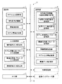
図1は、実施形態におけるモデリング装置の構成を示すブロック図である。実施形態のモデリング装置Sは、モデリングすべきシステムのモデルを前記モデルのパラメータの値を決定することによって構築する装置であって、前記モデルは、連続した時間と見なされる時間変数を含む数式であり、予め得られている前記システムに関する先験的情報を制約条件として設定する制約条件設定部と、所定の入力データを実績入力データとして前記システムに入力した場合に前記システムから出力された実績出力データと、前記実績入力データを前記モデルに入力した場合に前記モデルから出力されたモデル出力データとの誤差を評価する評価関数の評価結果を求める評価演算部と、前記制約条件設定部で設定された制約条件を満たし、かつ、前記評価演算部で演算された評価結果が最良となるように、前記モデルのパラメータの値を求めるモデル演算部とを備える装置である。 FIG. 1 is a block diagram illustrating a configuration of a modeling apparatus according to an embodiment. The modeling apparatus S of the embodiment is an apparatus for constructing a model of a system to be modeled by determining values of parameters of the model, and the model is a mathematical formula including a time variable regarded as a continuous time. A constraint condition setting unit that sets a priori information on the system obtained in advance as a constraint condition, and actual output data output from the system when predetermined input data is input to the system as actual input data And an evaluation calculation unit for obtaining an evaluation result of an evaluation function for evaluating an error from the model output data output from the model when the actual input data is input to the model, and set by the constraint condition setting unit The parameters of the model are such that the constraint condition is satisfied and the evaluation result calculated by the evaluation calculation unit is the best. A device and a model computation unit for determining the value of the data.
このようなモデリング装置Sは、例えば、図1に示すように、演算部1と、入力設定部2と、出力部3と、記憶部4と、これら演算部1、入力設定部2、出力部3および記憶部4の間で相互にデータを交換することができるようにこれらを互いに接続するバス5とを備えて構成される。
For example, as shown in FIG. 1, such a modeling apparatus S includes a
入力設定部2は、モデリング装置Sの演算開始指示等の各種コマンドや、例えば実績入出力データ等のシステムのモデル化に必要な各種データをモデリング装置Sに入力する機器であり、例えば、キーボードやマウス等である。そして、本実施形態では、入力設定部2は、制約条件を入力設定する制約条件入力設定部21と、モデル次数および同定パラメータを入力設定するモデル次数同定パラメータ入力設定部22と、最適化計算パラメータを入力設定する最適化計算パラメータ入力設定部23と、評価関数を入力設定する評価関数入力設定部24とを備えている。これら制約条件、モデル次数、同定パラメータおよび最適化計算パラメータは、システムのモデル化の際に利用されるように、モデリング装置Sの記憶部4に格納されることで、モデリング装置Sに設定される。
The
制約条件入力設定部21は、モデルの制約条件(先験的情報)を入力してモデリング装置Sに設定するためのものである。制約条件は、システムのモデル化の際に、このモデル化によって得られたモデルが満たすべき条件であり、本実施形態では、モデリング対象のシステムに関する先験的知識によって与えられる。先験的知識は、任意の手段によってシステムから得られる情報であり、例えば、システムの設計値や理論式等から計算によって推定される情報であって良く、また例えば、システムを設計した場合に過去の事例に照らして経験的に推測される情報であって良く、また例えば、システムを実際に組み、この実際のシステムを稼動させてこれを観察することによって得られる情報であって良い。この得られた先験的知識は、モデリング装置Sが取り扱うことができる形式で表現(表記、記述)され、先験的情報とされる。
The constraint condition
本実施形態では、予め決められた規範(基準)となるデータであって時間に依存する規範入力を入力データとしてシステムに与えた場合に、システムから出力される出力データ(計算によって得られる出力データ、および、システムで観測される実績出力データを含む)が制約条件(時間応答制約条件)とされる。規範入力は、例えば、ステップ状の入力(ステップ入力)、ランプ状の入力(ランプ入力)、三角関数波(例えばsin波)や三角波等の周期入力およびそれらの周波数掃引波(スイープ波、sweep波)等の、時間に関する所定の関数である。時間応答制約条件は、例えば前記出力データのそのものであって良く、また例えば前記出力データの上限値および/またはその下限値であって良く、さらにこれらに加えてその時間範囲が設定されて良い。すなわち、規範入力の入力時点を時刻0として、どの時刻tSからどの時刻tEまでの前記出力データが制約条件とされるのか、あるいは、どの時刻tSからどの時刻tEまでの前記出力データにおける上限値および/または下限値が制約条件とされるのか、が設定される(0≦tS<tE)。この時間応答制約条件が入力設定される場合、制約条件入力設定部21は、時間応答制約条件入力設定部として機能する。
In this embodiment, output data (output data obtained by calculation) output from a system when data that is a predetermined standard (reference) and a time-dependent standard input is given to the system as input data. And the actual output data observed by the system) are defined as the constraint conditions (time response constraint conditions). The reference input includes, for example, step input (step input), ramp input (ramp input), periodic input such as trigonometric function wave (for example, sin wave) and triangular wave, and frequency sweep waves (sweep wave, sweep wave). ) And the like. The time response constraint condition may be, for example, the output data itself, and may be, for example, the upper limit value and / or the lower limit value of the output data, and the time range may be set in addition to these. That is, when the input time point of the reference input is
なお、Aおよび/またはBは、AおよびBのうちの少なくとも一方の意味であり、AあるいはB、または、AとBとの両方の意味である。 A and / or B means at least one of A and B, and means A or B, or both A and B.
そして、本実施形態では、システムの定常ゲインの符号や、その範囲(定常ゲインの上限値および下限値)が制約条件(定常ゲイン制約条件)とされる。この定常ゲイン制約条件が入力設定される場合、制約条件入力設定部21は、定常ゲイン制約条件入力設定部として機能する。
In the present embodiment, the sign of the steady gain of the system and the range (upper limit value and lower limit value of the steady gain) are set as the constraint condition (steady gain constraint condition). When the steady gain constraint condition is input and set, the constraint condition
モデル次数未知パラメータ入力設定部22は、モデルの次数および前記モデルの同定パラメータを入力してモデリング装置Sに設定するためのものである。モデルの同定パラメータは、前記モデルにおけるパラメータのうち未知のパラメータとして同定すべきパラメータである。モデルの同定パラメータは、後述のシステムのモデルを作成する演算によってその値が決定され、これによってシステムのモデルが構築される。これらモデルの次数および同定パラメータは、例えば制御系設計に使用するためやシミュレーションに使用するため等の、モデリングの目的によって適宜に選定される。また、モデルの精度、モデル化に使用される入出力データの質や量、および、モデル化の情報処理量(計算量)等も勘案されて良い。
The model order unknown parameter
最適化計算パラメータ入力設定部23は、最適化計算パラメータを入力してモデリング装置Sに設定するためのものである。最適化計算パラメータは、最適化の計算を実行する際に必要とされる調整パラメータである。最適化計算パラメータは、本実施形態では、最適化計算手法として、後述するようにPSO(Particle Swarm Optimization)法が用いられていることから、このPSO法の演算に必要なパラメータであり、粒子pの個数P、解の更新回数(繰り返し回数)K、初期値の値域、後述の式におけるw、c1、c2である。最適化計算パラメータの入力設定の際に、モデルの次数や同定パラメータの個数が勘案されて良い。例えば、モデルの次数が大きくなるに従って、あるいは、同定パラメータの個数が多くなるに従って、探索すべき解空間が広くなるので、粒子pの個数Pや解の更新回数Kが大きく設定されることが好ましい。
The optimization calculation parameter
評価関数入力設定部24は、評価関数を入力してモデリング装置Sに設定するためのものである。評価関数は、同定パラメータのパラメータ値を決めた場合に、このパラメータ値によって規定されるモデルがシステムをどの程度よく表現しているか否かの度合い(モデルの精度)を示す値(評価値)を求める関数である。評価関数は、予め1つだけ設定され、プログラムに予め組み込まれていても良いが、本実施形態では、より適切にモデルを評価するために、評価関数入力設定部24から入力可能とされている。さらに、オペレータの便宜を図るために、本実施形態では、予め複数の評価関数が用意されており、これら複数の評価関数の中から評価関数入力設定部24を介して選定することで、評価関数が入力設定される。
The evaluation function
出力部3は、入力部2から入力されたコマンドやデータおよびモデリング装置Sの演算結果(システムのモデル)等を出力する機器であり、例えばCRTディスプレイ、LCD、有機ELディスプレイ又はプラズマディスプレイ等の表示装置やプリンタ等の印字装置等である。
The
記憶部4は、データやプログラムを記憶する例えばROM(Read Only Memory)およびEEPROM(Electrically Erasable Programmable Read Only Memory)等の不揮発性の記憶素子やハードディスク等を備えるとともに、演算部1が実行するモデリングプログラムや制御プログラム等の実行中における各データを一時的に記憶するいわゆるワーキングメモリであり、例えば揮発性の記憶素子であるRAM(Random Access Memory)を備えて構成される。記憶部4は、機能的に、制約条件記憶部41と、モデル次数同定パラメータ記憶部42と、最適化計算パラメータ記憶部43と、評価関数記憶部44と、モデル出力等記憶部45と、実績データ記憶部46とを備える。
The
制約条件記憶部41は、制約条件を記憶するものであり、制約条件入力設定部21から入力された制約条件が制約条件記憶部41に格納され、記憶される。制約条件記憶部41は、本実施形態では、時間応答制約条件を記憶する時間応答制約条件記憶部411と、定常ゲイン制約条件を記憶する定常ゲイン制約条件記憶部412とを備えている。
The constraint
モデル次数同定パラメータ記憶部42は、モデルの次数および前記モデルの同定パラメータを記憶するものであり、モデル次数同定パラメータ入力設定部22から入力されたモデルの次数および同定パラメータがモデル次数同定パラメータ記憶部42に格納され、記憶される。
The model order identification
最適化計算パラメータ記憶部43は、最適化計算パラメータを記憶するものであり、最適化計算パラメータ入力設定部23から入力された最適化計算パラメータが最適化計算パラメータ記憶部43に格納され、記憶される。
The optimization calculation
評価関数記憶部44は、評価関数を記憶するものであり、評価関数入力設定部24から入力された評価関数が評価関数記憶部44に格納され、記憶される。本実施形態では、上述したように、複数の所定の評価関数が予め記憶されており、これら複数の評価関数の中から1つの評価関数が評価関数入力設定部24から選定され、この選定されたことを示す情報も評価関数記憶部44に記憶される。
The evaluation
モデル出力等記憶部45は、モデルを規定する所定のパラメータ値に対し、演算部1で演算されたモデル出力、評価結果および制約条件を満たすか否かの情報を互いに対応付けて記憶するものである。前記所定のパラメータ値は、本実施形態では、PSO法によって与えられる値である。そして、本実施形態では、制約条件を満たすか否かの情報は、評価結果を示す評価値に変えられ、評価結果としてモデル出力等記憶部45に記憶される。このように制約条件を満たすか否かの情報が評価結果を示す評価値に変換されて評価結果としてモデル出力等記憶部45に記憶されることで、モデルのパラメータの値を決定する際に、評価結果を参酌するだけで済み、このモデルのパラメータの値を決定する処理が簡便化される。
The model output
実績データ記憶部46は、実績データを記憶するものである。実績データは、モデリング対象のシステムに入力(印加)される所定の入力データ(実績入力データ)、および、この入力データの入力によってシステムから出力される出力データ(実績出力データ)であり、これら実績入力データおよび実績出力データ(実績入出力データ)は、互いに対応付けて実績データ記憶部43に記憶される。前記所定の入力データは、任意のデータであって良く、例えば、ステップ状の入力データ、ランダム入力データおよび擬似白色系列(例えばM系列等)データ等の時系列データである。出力データもこれに対応して時系列データとなる。前記所定の入力データは、制御工学の分野では、同定入力と呼ばれる。時系列入力データおよび時系列出力データは、1組であっても良く、また複数の組であっても良い。複数の組である場合には、時系列入出力データの各組は、同日に得られたデータであっても良く、また、異なる日に得られたデータであって良い。そして、これら複数の組の時系列入出力データは、モデリングの際に、これらの中から適宜に選択されるようにモデリング装置Sが構成されてもよい。
The record
演算部1は、例えば、マイクロプロセッサおよびその周辺回路等を備えて構成され、プログラムに従い入力設定部2、出力部3および記憶部4を当該機能に応じてそれぞれ制御することによってモデリング装置S全体の制御を司るものであって、モデリング対象のシステムのモデルを前記モデルのパラメータの値を決定することによって構築するものである。演算部1は、機能的に、モデル出力演算部11と、制約条件評価部12と、評価演算部13と、モデル更新決定部14とを備える。
The
モデル出力演算部11は、モデル次数、同定パラメータおよび最適化計算パラメータを設定することによって設定された前記システムのモデルに、入力データを入力(印加)することで前記モデルの出力データ(モデル出力データ)を求めるものである。この求めたモデル出力データは、モデル出力等記憶部45に記憶され、格納される。
The model
制約条件評価部12は、モデル出力演算部11によって得られたモデル出力データが制約条件を満たしているか否かを評価するものである。この評価したモデル出力データが制約条件を満たしているか否かの情報は、モデル出力等記憶部45に記憶され、格納される。
The constraint
評価演算部13は、予め決められた所定の入力データを実績入力データとしてシステムに入力した場合にこのシステムから出力された実績出力データと、前記実績入力データを前記システムのモデルに入力した場合にこのモデルから出力されたモデル出力データとの誤差を評価する評価関数の評価結果を求めるものである。この求めた評価結果は、モデル出力等記憶部45に記憶され、格納される。
The
モデル更新決定部14は、前記システムのモデルを予め決められた所定の更新則に従って更新するとともに、制約条件入力設定部21で設定された制約条件を満たし、かつ、評価演算部13で演算された評価結果が最良となるように、前記システムのモデルにおけるそのパラメータの値を求め、前記システムのモデルを決定するものである。
The model
このようなモデリング装置Sは、モデリング方法のプログラム(ソフトウェア)を実装することで、例えば、デスクトップ型パソコンやノート型パソコン等のコンピュータによって構成可能である。 Such a modeling apparatus S can be configured by a computer such as a desktop personal computer or a notebook personal computer by mounting a program (software) of a modeling method.
なお、必要に応じてモデリング装置Sは、図1に破線で示す外部記憶部6や通信インターフェース部7をさらに備えてもよい。
Note that the modeling apparatus S may further include an
外部記憶部6は、例えば、フレキシブルディスク、CD−ROM(Compact Disc Read Only Memory)、CD−R(Compact Disc Recordable)およびDVD−R(Digital Versatile Disc Recordable)等の記録媒体との間でデータを読み込みおよび/または書き込みを行う装置であり、例えば、フレキシブルディスクドライブ、CD−ROMドライブ、CD−Rドライブ及びDVD−Rドライブ等である。通信インターフェース部7は、通信網(ネットワーク)に接続され、この通信網を介して他の装置との間で通信信号を送受信するための機器である。
The
各プログラムが格納されていない場合には、これらを記録した記録媒体から外部記憶部6を介して記憶部4にインストールされるように構成してもよく、また、これらプログラムを管理するサーバコンピュータ(不図示)から通信網および通信インターフェース部7を介して各プログラムがダウンロードされるように構成してもよい。また、システムのモデル化の演算に当たってモデリング装置Sに入力すべき例えば実績入出力データ等のデータは、このデータを記憶した記録媒体によって外部記憶部6を介してモデリング装置Sに入力されるように構成してもよく、また、このデータを管理するサーバコンピュータから通信網および通信インターフェース部7を介してモデリング装置Sに入力されるように構成してもよい。
When each program is not stored, it may be configured to be installed in the
次に、本実施形態におけるモデリング装置の動作について説明する。図2は、実施形態におけるモデリング装置の概略動作を示すフローチャートである。図3は、実施形態のモデリング装置における制約条件の設定動作を示すフローチャートである。図4は、実施形態のモデリング装置におけるモデルの演算動作を示すフローチャートである。 Next, the operation of the modeling apparatus in this embodiment will be described. FIG. 2 is a flowchart showing a schematic operation of the modeling apparatus in the embodiment. FIG. 3 is a flowchart showing the setting operation of the constraint condition in the modeling apparatus of the embodiment. FIG. 4 is a flowchart illustrating a calculation operation of a model in the modeling apparatus according to the embodiment.
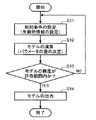
本実施形態のモデリング装置Sでは、概略、図2に示すように、まず、ステップS11では、制約条件が設定され、続いて、ステップS12では、モデルを構築すべく、制約条件を満たし、かつ、評価結果が最良となるように、モデルのパラメータの値を決定することによって、モデルが演算される。続いて、ステップS13では、この演算されたモデルの精度が予め決められた許容範囲以内であるか否かが判定され、この判定の結果、モデルの精度が許容範囲以内ではない場合(NO)には処理がステップS11に戻され、一方、モデルの精度が許容範囲内である場合(YES)にはステップS14が実行され、この演算されたモデルがシステムのモデルとして出力部3に出力され、出力部3で出力される。
In the modeling apparatus S of the present embodiment, as schematically shown in FIG. 2, first, in step S11, a constraint condition is set, and then in step S12, the constraint condition is satisfied in order to construct a model, and The model is calculated by determining the values of the model parameters so that the evaluation result is the best. Subsequently, in step S13, it is determined whether or not the calculated accuracy of the model is within a predetermined allowable range. If the result of this determination is that the accuracy of the model is not within the allowable range (NO). Is returned to step S11. On the other hand, if the accuracy of the model is within the allowable range (YES), step S14 is executed, and the calculated model is output to the
次に、前記ステップS11についてより具体的に説明する。図3において、まず、ステップS21では、入力設定部2の制約条件入力設定部21から、時間応答波形における制約条件(前記時間応答制約条件)が入力され、記憶部4の制約条件記憶部41における時間応答制約条件記憶部411に格納され、記憶される。これによって、後述するように、演算部1の制約条件評価部12が時間応答制約条件記憶部411に記憶されている時間応答制約条件を用いることで、この時間応答制約条件を満たすように、システムのモデルが構築される。
Next, the step S11 will be described more specifically. In FIG. 3, first, in step S <b> 21, a constraint condition in the time response waveform (the time response constraint condition) is input from the constraint condition
以下に、説明の簡単化のため、1入力1出力系のシステムの場合について、より具体的に説明する。もちろん、以下の説明は、一般性を損なうことなく、多入力多出力系のシステムに拡張可能である。 Hereinafter, for simplification of description, the case of a system with one input and one output will be described more specifically. Of course, the following description can be extended to a multi-input multi-output system without loss of generality.
まず、例えば燃焼炉プラント等の実際のシステムから入出力データ(入力データUdataおよび出力データYdata)が実績入出力データ(実績入力データUdataおよび実績出力データYdata)として取得され、実績データ記憶部46に格納され、記憶されているものとする。システムのモデルが連続した時間と見なされる時間変数tを含む連続時間状態空間モデル式または連続時間伝達関数モデル式であることから、実績入出力データUdata、Ydataは、時間的に連続しているデータに見えるように、より短いサンプリング間隔で取得されることが好ましい。ここでは、表記の簡単化のために、1秒間隔(1秒周期)でサンプリングされているものとする。サンプリング開始の時刻0から時刻tmaxまでのtmax秒間における実績入出力データUdata、Ydataは、時刻t秒の入力値をu(t)とし、時刻t秒の出力値をy(t)とする場合には、それぞれ、次の式1−1、式1−2となる。
Udata=[u(0) u(1) ・・・ u(tmax)]T ・・・(1−1)
Ydata=[y(0) y(1) ・・・ y(tmax)]T ・・・(1−2)
ここで、上付き添え字Tは、いわゆる転置を表す記号である。
First, for example, input / output data (input data U data and output data Y data ) is acquired as actual input / output data (actual input data U data and actual output data Y data ) from an actual system such as a combustion furnace plant. It is assumed that it is stored and stored in the
U data = [u (0) u (1)... U (t max )] T (1-1)
Y data = [y (0) y (1)... Y (t max )] T (1-2)
Here, the superscript T is a symbol representing transposition.
時刻0から時刻tEまでのtE秒間における式2の規範入力Urをシステムに加えた場合に得られる出力データに関し、時刻tS1から時刻tE1までの間における上限Ymaxおよび時刻tS2から時刻tE2までの間における下限Yminを式3−1および式3−2とすると、これら式3−1によって記述される上限Ymaxおよび式3−2によって記述される下限Yminが制約条件入力設定部21からモデリング装置Sに与えられる。
Ur=[ur(0) ur(1) ・・・ ur(tE)]T ・・・(2)
Ymax=[ymax(ts1) ymax(ts1+1) ・・・ ymax(tE1)]T ・・・(3−1)
Ymin=[ymin(ts2) ymin(ts2+1) ・・・ ymin(tE2)]T ・・・(3−2)
ここで、ur(t)は、時刻t秒における入力値であり、ymax(t)は、時刻tにおける出力値の上限値であり、そして、ymin(t)は、時刻tにおける出力値の下限値である。また、0≦tS1<tE1≦tEであり、0≦tS2<tE2≦tEである。
Relates to an output data obtained when added normative input U r of
U r = [u r (0 ) u r (1) ··· u r (t E)] T ··· (2)
Y max = [y max (t s1 ) y max (t s1 +1)... Y max (t E1 )] T (3-1)
Y min = [y min ( ts 2 ) y min ( ts 2 +1)... Y min (t E2 )] T (3-2)
Here, u r (t) is an input value at time t seconds, y max (t) is an upper limit value of an output value at time t, and y min (t) is an output value at time t. This is the lower limit of the value. Also, 0 ≦ t S1 <t E1 ≦ t E , and 0 ≦ t S2 <t E2 ≦ t E.
なお、規範入力の一具体例として、単位ステップ入力は、Ur=[0 1 1 ・・・ 1]Tであり、単位インパルス入力は、Ur=[0 1 0 ・・・ 0]Tであり、またランプ入力は、Ur=[0 1 2 3 ・・・]Tである。また、規範入力は、1種類であって良く、また複数の種類であっても良い。 As a specific example of the normative input, the unit step input is U r = [0 1 1... 1] T , and the unit impulse input is U r = [0 1 0... 0] T. There also ramp input is U r = [0 1 2 3 ···] T. Further, the normative input may be one type or a plurality of types.
続いて、ステップS22では、入力設定部2の制約条件入力設定部21から、定常ゲインにおける制約条件(前記定常ゲイン制約条件)が入力され、記憶部4の制約条件記憶部41における定常ゲイン制約条件記憶部412に格納され、記憶される。例えば、システムの定常ゲインGがGmin≦G≦Gmaxとすると、これら下限値Gminおよび上限値Gmaxが制約条件入力設定部21からモデリング装置Sに与えられる。これによって、後述するように、演算部1の制約条件評価部12が定常ゲイン制約条件記憶部412に記憶されている定常ゲイン制約条件を用いることで、この定常ゲイン制約条件を満たすように、システムのモデルが構築される。
Subsequently, in step S <b> 22, the constraint condition for the steady gain (the steady gain constraint condition) is input from the constraint condition
次に、前記ステップS12についてより具体的に説明する。図4において、まず、ステップS31では、入力設定部2のモデル次数同定パラメータ入力設定部22から、モデルの次数および前記モデルの同定パラメータが入力され、記憶部4のモデル次数同定パラメータ記憶部42に格納され、記憶される。
Next, the step S12 will be described more specifically. In FIG. 4, first, in step S <b> 31, the model order and the model identification parameter are input from the model order identification parameter
上述の1入力1出力系のシステムの場合において、より具体的に説明すると、例えば、モデリング対象のシステムに対する連続時間状態空間モデル式が式4(式4−1、式4−2)であるとする。
dx(t)/dt=Ax(t)+Bu(t) ・・・(4−1)
ym(t)=Cx(t)+Du(t) ・・・(4−2)
ここで、x(t)は、n次の状態ベクトルであり、ym(t)は、モデルの出力(モデル出力、モデルによる計算値)であり、A、B、CおよびDは、それぞれn行n列、n行1列、1行n列および1行1列の定数行列である。ここでは、説明の簡単化のため、モデリング対象のシステムが厳密にプロパーである、すなわち、D=0とする。
More specifically, in the case of the above-described one-input one-output system, for example, the continuous-time state space model expression for the system to be modeled is Expression 4 (Expression 4-1 and Expression 4-2). To do.
dx (t) / dt = Ax (t) + Bu (t) (4-1)
y m (t) = Cx (t) + Du (t) (4-2)
Here, x (t) is an n-order state vector, y m (t) is a model output (model output, calculated value by model), and A, B, C, and D are each n It is a constant matrix of row n columns,
モデルの次数は、このnの値であり、この値nがモデルの次数としてモデル次数同定パラメータ入力設定部22から入力される。この例では、n=2、すなわち、モデルの次数が2である2次のモデルを求めるものとする。また、定数行列A、BおよびCは、例えば可制御正準形式等の所定の形式でよいが、冗長なパラメータが無い方が好ましいことから、この例では、可観測正準形式であるとし、それぞれ式5−1、式5−2および式5−3となる。
The model order is the value of n, and this value n is input from the model order identification parameter
ここで、a0、a1、b0およびb1は、モデルを規定する未知パラメータである。これらa0、a1、b0およびb1の未知パラメータが、モデル次数同定パラメータ入力設定部22から入力され、同定パラメータとして指定される。すなわち、モデリング対象のシステムのモデルを構築することは、これら同定パラメータとして指定された未知パラメータa0、a1、b0およびb1の各値を求めることである。
Here, a 0 , a 1 , b 0 and b 1 are unknown parameters that define the model. These unknown parameters of a 0 , a 1 , b 0 and b 1 are input from the model order identification parameter
なお、式4(式4−1、式4−2)および式5(式5−1〜式5−3)の求解は、式6の連続時間伝達関数モデル式G(s)を求めること、すなわち、式6の連続時間伝達関数モデル式G(s)における未知パラメータa0、a1、b0およびb1を求めることと等価である。
G(s)=(b1s+b0)/(s2+a1s+a0) ・・・(6)
In addition, the solution of Formula 4 (Formula 4-1, Formula 4-2) and Formula 5 (Formula 5-1 to Formula 5-3) calculates | requires the continuous time transfer function model formula G (s) of
G (s) = (b 1 s + b 0 ) / (s 2 + a 1 s + a 0 ) (6)
続いて、ステップS32では、入力設定部2の最適化計算パラメータ入力設定部23から、最適化計算パラメータが入力され、記憶部4の最適化計算パラメータ記憶部43に格納され、記憶される。
Subsequently, in step S32, optimization calculation parameters are input from the optimization calculation parameter
上述の1入力1出力系のシステムの場合において、より具体的に説明すると、未知パラメータ(同定パラメータ)a0、a1、b0およびb1の同定は、本実施形態では、例えば、PSO(Particle Swarm Optimization)法が用いられる。このPSO法は、解空間に複数P個の粒子p(粒子群)をランダム(無作為)にばらまき、これら解空間にばらまかれた粒子群が所定の更新則に従って解空間内を移動しながら、最適解を探索する手法である。このPSO法を本実施形態に適用する場合では、解空間は、未知パラメータ(同定パラメータ)a0、a1、b0およびb1を各座標軸とする座標空間(この例では4次元空間)であり、粒子pは、4次元ベクトルで表される前記座標空間上の点となり、更新回数k番目におけるP個のうちのi番目の粒子p(i,k)は、式7によって表現されることになる。
p(i,k)=[a0 a1 b0 b1]T ・・・(7)
More specifically, in the case of the above-described one-input one-output system, the unknown parameters (identification parameters) a 0 , a 1 , b 0 and b 1 are identified by, for example, PSO ( Particle Swarm Optimization) method is used. In this PSO method, a plurality of P particles p (particle groups) are randomly (randomly) dispersed in the solution space, and the particle groups dispersed in these solution spaces move in the solution space according to a predetermined update rule. This is a technique for searching for an optimal solution. When this PSO method is applied to this embodiment, the solution space is a coordinate space (in this example, a four-dimensional space) with unknown parameters (identification parameters) a 0 , a 1 , b 0 and b 1 as coordinate axes. Yes, the particle p is a point on the coordinate space represented by a four-dimensional vector, and the i-th particle p (i, k) among the P particles at the k-th update count is expressed by Equation 7. become.
p (i, k) = [a 0 a 1 b 0 b 1 ] T (7)
以下、適宜、このp(i,k)の[a0 a1 b0 b1]Tをパラメータセットと呼称することとする。 Hereinafter, [a 0 a 1 b 0 b 1 ] T of p (i, k) will be referred to as a parameter set as appropriate.
このような最適化手法では、粒子pの個数P(0<i≦P)、更新回数K(0<k≦K)および所定の更新則におけるパラメータ(後述のw、c1、c2)が最適化計算パラメータであり、最適化計算パラメータ入力設定部23から入力される。
In such an optimization method, the number P of particles p (0 <i ≦ P), the number of updates K (0 <k ≦ K), and parameters (w, c 1 , c 2 described later) in a predetermined update rule are set. It is an optimization calculation parameter, and is input from the optimization calculation parameter
続いて、ステップS33では、入力設定部2から評価関数が入力され、設定される。
Subsequently, in step S33, an evaluation function is input from the
上述の1入力1出力系のシステムの場合において、より具体的に説明すると、評価関数は、例えば、本実施形態では、実績入力データUdataに対応する実績出力データYdata(=[y(0) y(1) ・・・ y(tmax)]T)と、前記実績入力データUdataをモデル(上述の例では、式4(式4−1、式4−2)および式5(式5−1〜式5−3)または式6)に入力した場合にこのモデルから出力されるモデル出力データYi(=[yi(0) yi(2) ・・・ yi(tmax)]T)との誤差を評価する関数である。このような評価関数Jiは、例えば、式8−1によって与えられる。
Ji=||W・(Yi−Ydata)|| ・・・(8−1)
ここで、||v||は、いわゆる、ベクトルvのユークリッドノルムを表し、vが縦ベクトルである場合では、||v||=√(vTv)である。また、Wは、出力の予測誤差に対していずれの部分を重要視して評価するかを定める重み行列であり、例えば対角行列とする。
More specifically, in the case of the above-described one-input / one-output system, the evaluation function is, for example, the actual output data Y data (= [y (0) corresponding to the actual input data U data in this embodiment. ) Y (1)... Y (t max )] T ) and the actual input data U data in the model (in the above example, Expression 4 (Expression 4-1, Expression 4-2) and Expression 5 (Expression Model output data Y i (= [y i (0) y i (2)... Y i (t max ) output from this model when input to 5-1 to 5-3) or 6) )] A function for evaluating an error from T ). Such an evaluation function J i is given by, for example, Expression 8-1.
J i = || W · (Y i -Y data ) || (8-1)
Here, || v || represents a so-called Euclidean norm of vector v, and | v || = v (v T v) when v is a vertical vector. W is a weighting matrix that determines which part of the output prediction error should be evaluated with importance, for example, a diagonal matrix.
また例えば、評価関数Jiは、例えば、式8−2によって与えられる無限ノルムである。
Ji=||W・(Yi−Ydata)||∞ ・・・(8−2)
ここで、||v||∞は、いわゆる、ベクトルvの無限ノルム(最大値ノルム)を表し、v=[v1 v2 ・・・ vn]Tである場合では、||v||∞=max(|v1|、|v2|、・・・、|vn|)である。
Further, for example, the evaluation function J i is an infinite norm given by, for example, Expression 8-2.
J i = || W · (Y i -Y data ) || ∞ (8-2)
Here, || v || ∞ represents a so-called infinite norm (maximum norm) of vector v, and in the case of v = [v 1 v 2 ... V n ] T , || v || ∞ = max (| v 1 |, | v 2 |,..., | V n |).
また例えば、評価関数Jiは、例えば、式8−3によって与えられる。
Ji=||W・(Yi−Ydata)||1 ・・・(8−3)
ここで、||v||1は、いわゆる、ベクトルvの1ノルムを表し、v=[v1 v2 ・・・ vn]Tである場合では、||v||1=Σ|vi|である。ただし、Σは、i=1からi=nまでの和である。
For example, the evaluation function J i is given by, for example, Expression 8-3.
J i = || W · (Y i -Y data ) || 1 (8-3)
Here, || v || 1 represents a so-called 1-norm of vector v. When v = [v 1 v 2 ... V n ] T , || v || 1 = Σ | v i |. However, Σ is the sum from i = 1 to i = n.
評価関数記憶部44には、例えば、このような複数の評価関数Ji(式8−1〜式8−3)が記憶されており、これら複数の評価関数Jiの中から、評価関数入力設定部24を介して1つの評価関数Jiが選定され、入力設定される。
The evaluation
なお、このような評価関数Jが、実績出力データとモデル出力データとの誤差に重み付けを行う重みWを有し、この重みWが、その値が大きいほど評価関数Jによる評価結果に大きく影響を与えるものである場合に、この重みWの値は、所定の閾値以上のノイズを含む実績出力データに対応する区間に対し、前記区間を除く他の区間よりも相対的に小さくなるように設定されてよい。このような前記区間およびその重みWならびに前記他の区間およびその重みWは、例えば、入力設定部2の最適化計算パラメータ入力設定部23から入力設定される。このように構成することによって、所定の閾値以上のノイズを含む実績出力データの、評価結果に与える影響が低減され、システムのモデルをより高精度に構築することができる。
Note that such an evaluation function J has a weight W for weighting the error between the actual output data and the model output data. The larger the value of the weight W, the greater the influence on the evaluation result by the evaluation function J. When given, the value of the weight W is set to be relatively smaller than the other sections excluding the section with respect to the section corresponding to the actual output data including noise of a predetermined threshold value or more. It's okay. Such an interval and its weight W and the other interval and its weight W are input and set, for example, from the optimization calculation parameter
続いて、ステップS34では、演算部1のモデル出力演算部11によって、モデル出力が演算され、記憶部4のモデル出力等記憶部45に記憶される。
Subsequently, in
上述の1入力1出力系のシステムの場合において、より具体的に説明すると、まず、P個の粒子p(i,0)(更新回数k=0、i=0〜P)、例えば100個の粒子p(i,0)(i=0〜100)の初期値が例えば乱数を生成することによってランダムに設定される。これによってP個の各パラメータセットp(i,0)の値が設定される。そして、i番目の粒子p(i,0)の移動速度v(i,0)の初期値が例えばv(i,0)=[0 0 0 0]Tに設定される。 More specifically, in the case of the above-described one-input one-output system, first, P particles p (i, 0) (update count k = 0, i = 0 to P), for example, 100 particles The initial value of the particle p (i, 0) (i = 0 to 100) is set randomly by generating a random number, for example. As a result, the value of each of the P parameter sets p (i, 0) is set. The initial value of the moving speed v (i, 0) of the i-th particle p (i, 0) is set to v (i, 0) = [0 0 0 0] T , for example.
ここで、制約条件として、モデリング対象のシステムが安定な系であることが、先験的知識として判明している場合には、a0>0かつa1>0の範囲で、i番目の粒子p(i,0)の初期値がランダムに設定されることが好ましい。 Here, as a constraint, if it is known as a priori knowledge that the system to be modeled is a stable system, the i-th particle is in the range of a 0 > 0 and a 1 > 0. It is preferable that the initial value of p (i, 0) is set at random.
また、制約条件として、モデリング対象のシステムにおける定常ゲインが正の値であることが、先験的知識として判明している場合には、b0の符号とa0の符号が等しくなるように、すなわち、b0×a0>0となるように、i番目の粒子p(i,0)の初期値がランダムに設定されることが好ましい。 Further, as a constraint, when it is known as a priori knowledge that the steady-state gain in the system to be modeled is a positive value, the sign of b 0 and the sign of a 0 are equal. That is, it is preferable that the initial value of the i-th particle p (i, 0) is set at random so that b 0 × a 0 > 0.
また、制約条件として、モデリング対象のシステムに不安定なゼロ点がないことが、先験的知識として判明している場合には、b1の符号とb0の符号が等しくなるように、すなわち、b1×b0>0となるように、i番目の粒子p(i,0)の初期値がランダムに設定されることが好ましい。 As a constraint, when it is known as a priori knowledge that there is no unstable zero point in the system to be modeled, the sign of b 1 is equal to the sign of b 0 , that is, , It is preferable that the initial value of the i-th particle p (i, 0) is set at random so that b 1 × b 0 > 0.
また、制約条件として、モデリング対象のシステムにおける定常ゲインがGmin以上かつGmax以下であることが、先験的知識として判明している場合には、a0×Gmin≦b0≦a0×Gmaxを満たすように、i番目の粒子p(i,0)の初期値がランダムに設定されることが好ましい。 Also, as a constraint, if it is known as a priori knowledge that the steady-state gain in the system to be modeled is G min or more and G max or less, a 0 × G min ≦ b 0 ≦ a 0 The initial value of the i-th particle p (i, 0) is preferably set at random so as to satisfy × Gmax .
このようにi番目の粒子p(i,0)の初期値を設定する際に、制約条件を加味することによって、解が存在しない領域を探索する無駄を省くことが可能となる。 In this way, when setting the initial value of the i-th particle p (i, 0), it is possible to eliminate the waste of searching for an area where no solution exists by adding a constraint condition.
このようにP個の粒子pの値をそれぞれ設定することで、1個の粒子pに対応して1個のモデルが規定される。すなわち、i番目の粒子p(i,0)に対応して1個のモデルが規定される。上述の例では、100個の各粒子pのそれぞれに対応して100個のモデルが規定されることになる。 By setting the values of P particles p in this way, one model is defined corresponding to one particle p. That is, one model is defined corresponding to the i-th particle p (i, 0). In the above example, 100 models are defined corresponding to each of the 100 particles p.
このi番目の粒子p(i,0)に対応して規定されるモデル(この例では式4および式5によって表現されるモデル、あるいは、式6によって表現されるモデル)に対し、実績データ記憶部46に記憶されている実績入力データUdataが代入され、モデル出力データYiが得られ、この得られたモデル出力データYiが記憶部4のモデル出力等記憶部45にi番目の粒子p(i,0)に対応付けて記憶される。このモデル出力データYiの計算には、公知の制御系シミュレーションソフトウェア、例えば、The Math Work社のMATLAB/Simulink等が用いられる。このようにP個の各パラメータセットp(i,k)のそれぞれに対し、モデル出力が演算され、記憶部4のモデル出力等記憶部45にパラメータセットp(i,k)に対応付けて記憶される。
For the model defined in correspondence with the i-th particle p (i, 0) (in this example, the model represented by the
続いて、ステップS35では、制約条件評価部12によって、制約条件が評価され、この評価結果が記憶部4のモデル出力等記憶部45にパラメータセットp(i,k)に対応付けて記憶される。
Subsequently, in step S35, the constraint condition is evaluated by the constraint
上述の1入力1出力系のシステムの場合において、より具体的に説明すると、ステップS34と同様に、このi番目の粒子p(i,0)に対応して規定されるモデルに対し、所定の規範入力Urが代入され、前記所定の規範入力Urに対応するモデル出力データYri(=[yri(0) yri(1) ・・・ yri(tmax)]T)が得られる。そして、この得られた前記所定の規範入力Urに対応するモデル出力データYriが規範入力に対する制約条件を満たしているか否かが判断される。例えば、制約条件として、時刻tS1から時刻tE1までの間における上限値Ymaxおよび時刻tS2から時刻tE2までの間における下限値Yminが設定されている場合には、この前記所定の規範入力Urに対応するモデル出力データYriが時刻tS1から時刻tE1までの間で上限Ymax以下で、かつ、時刻tS2から時刻tE2までの間で下限Ymin以上であるか否かが判断される。この判断の結果、この前記所定の規範入力Urに対応するモデル出力データYriが時刻tS1から時刻tE1までの間で上限Ymax以下で、かつ、時刻tS2から時刻tE2までの間で下限Ymin以上ではない場合には、この前記所定の規範入力Urに対応するモデル出力データYriが制約条件を満たさないものとされ、この制約条件の評価結果が記憶部4のモデル出力等記憶部45にi番目の粒子p(i,0)に対応付けて記憶される。このようにP個の各パラメータセットp(i,k)のそれぞれに対し、制約条件が評価され、この評価結果が記憶部4のモデル出力等記憶部45にパラメータセットp(i,k)に対応付けて記憶される。
More specifically, in the case of the above-described one-input / one-output system, as in step S34, a predetermined model is used for the model defined corresponding to the i-th particle p (i, 0). The reference input U r is substituted to obtain model output data Y ri (= [y ri (0) y ri (1)... Y ri (t max )] T ) corresponding to the predetermined reference input U r. It is done. Then, whether the model output data Y ri corresponding to the obtained predetermined normative input U r satisfies the constraints of the Code input is determined. For example, when the upper limit value Y max between the time t S1 and the time t E1 and the lower limit value Y min between the time t S2 and the time t E2 are set as constraints, the predetermined value Whether the model output data Y ri corresponding to the reference input U r is less than or equal to the upper limit Y max between time t S1 and time t E1 and greater than or equal to the lower limit Y min between time t S2 and time t E2 It is determined whether or not. As a result of this determination, the model output data Y ri corresponding to the predetermined normative input U r is not more than the upper limit Y max from time t S1 to time t E1 and from time t S2 to time t E2 . If not more than the lower limit Y min is between the model output data Y ri corresponding to the predetermined norm input U r is assumed that does not satisfy the constraint conditions, evaluation results of the constraints of the
なお、上述では、粒子p(i,0)の初期値の設定の際に、定常ゲインGの制約条件を考慮したが、定常ゲインGの下限値Gminおよび上限値Gmaxが制約条件として設定されている場合に、実績入力データUdataに対応するモデル出力データYiが下限値Gmin以上であって、かつ、上限値Gmax以下であるか否かが判断されることで、定常ゲインGの制約条件が評価されても良い。 In the above description, the constraint condition of the steady gain G is considered when setting the initial value of the particle p (i, 0). However, the lower limit value G min and the upper limit value G max of the steady gain G are set as the constraint condition. If the model output data Y i corresponding to the actual input data U data is not less than the lower limit G min and not more than the upper limit G max , the steady gain is determined. The constraint condition of G may be evaluated.
続いて、ステップS36では、評価演算部13によって、評価関数による評価値が演算され、記憶部4のモデル出力等記憶部45に記憶される。
Subsequently, in step S <b> 36, the evaluation value by the evaluation function is calculated by the
上述の1入力1出力系のシステムの場合において、より具体的に説明すると、i番目の粒子p(i,0)に対応して規定されるモデルに対し、前記評価関数Jiによる評価値が演算され、この評価関数Jiの評価値が記憶部4のモデル出力等記憶部45にi番目の粒子p(i,0)に対応付けて記憶される。このようにP個の各パラメータセットp(i,k)のそれぞれに対し、評価関数による評価値が演算され、記憶部4のモデル出力等記憶部45にパラメータセットp(i,k)に対応付けて記憶される。
More specifically, in the case of the above-described one-input one-output system, the evaluation value by the evaluation function J i is given to the model defined corresponding to the i-th particle p (i, 0). The evaluation value of the evaluation function J i is calculated and stored in the model output
ここで、上記制約条件の評価結果を記憶部4のモデル出力等記憶部45にi番目の粒子p(i,0)に対応付けて記憶する際に、上述のように、この制約条件の評価結果そのものを記憶部4のモデル出力等記憶部45にi番目の粒子p(i,0)に対応付けて記憶してもよいが、本実施形態では、この制約条件の評価結果が評価関数Jiの評価値で記憶部4のモデル出力等記憶部45にi番目の粒子p(i,0)に対応付けて記憶される。例えば、制約条件を満たさない場合に、評価が悪いことを示す評価値が記憶部4のモデル出力等記憶部45にi番目の粒子p(i,0)に対応付けて記憶される。より具体的には、例えば、評価関数Jiが、評価が高いほどその評価値が小さくなるように構成されている場合では、制約条件を満たさない場合に、例えばモデル出力データYiがその値として取り得ない大きな評価値が、記憶部4のモデル出力等記憶部45にi番目の粒子p(i,0)に対応付けて記憶される。また例えば、評価関数Jiが、その取り得る値の範囲が負であるように構成されている場合では、制約条件を満たさない場合に、正の値(例えば固定値や制約条件の外れ度合いに従った値等)が記憶部4のモデル出力等記憶部45にi番目の粒子p(i,0)に対応付けて記憶される。このような評価関数Jiは、例えば、式8−4によって与えられる。
Ji=tan−1(||W・(Yi−Ydata)||)−π/2 ・・・(8−4)
Here, as described above, when the evaluation result of the constraint condition is stored in the model output
J i = tan −1 (|| W · (Y i −Y data ) ||) −π / 2 (8-4)
続いて、ステップS37では、モデル更新決定部14によって、最適化方法の繰り返し計算における更新が終了しているか否かが判断され、この判断の結果、更新が終了していない場合(NO)では、ステップS38の処理が実行され、一方、更新が終了している場合(YES)では、ステップS39の処理が実行される。更新回数Kは、任意の回数で良いが、PSO法では、解の精度や演算処理量等を考慮することによって適宜な回数に設定され、例えば、K=100回とされる。
Subsequently, in step S37, the model
ステップS38では、モデル更新決定部14によって、所定の更新則に従って更新され、処理がステップS34に戻される。
In step S38, the model
上述の1入力1出力系のシステムの場合において、より具体的に説明すると、k回目(k=0,1,2,・・・、K)の更新時点において、P個の各粒子pの中からその評価関数Jの値が最も小さい粒子pが探索され、第1最良評価粒子p(best,k)とされる。例えば、k回目の更新時点において、q番目の粒子p(q、k)の評価関数Jqの値が最も小さい場合には、p(best,k)=p(q,k)である。 More specifically, in the case of the above-described one-input / one-output system, at the update time of the k-th (k = 0, 1, 2,..., K), The particle p having the smallest value of the evaluation function J is searched and is set as the first best evaluation particle p (best, k). For example, when the value of the evaluation function J q of the q-th particle p (q, k) is the smallest at the k-th update time point, p (best, k) = p (q, k).
また、i番目の粒子pにおいて、0回目(初期値)からk−1回目までの中で評価関数Jの値が最も小さい粒子pが探索され、第2最良評価粒子p(i,best)とされる。例えば、r回目の更新時点において、i番目の粒子p(i、r)の評価関数Jiの値が最も小さい場合には、p(i,best)=p(i,r)である。なお、k=0の場合では、それぞれの初期値そのものが各粒子pのp(i,best)である。 In the i-th particle p, the particle p having the smallest value of the evaluation function J from the 0th (initial value) to the (k-1) th time is searched, and the second best evaluation particle p (i, best) Is done. For example, when the value of the evaluation function J i of the i-th particle p (i, r) is the smallest at the r-th update time, p (i, best) = p (i, r). When k = 0, each initial value itself is p (i, best) of each particle p.
そして、例えば、式9(式9−1、式9−2)によって与えられる更新則に従って、各粒子pの速度および位置がそれぞれ決定され、更新される。
v(i,k+1)=wv(i,k)
+c1R1ik(p(i,best)−p(i,k))
+c2R2ik(p(best,k)−p(i,k)) ・・・(9−1)
p(i,k+1)=p(i,k)+v(i,k+1) ・・・(9−2)
ここで、w、c1、c2は、それぞれ、調整パラメータであり、最適化計算パラメータとして上述したように最適化計算パラメータ入力設定部23から入力され、設定される。例えば、w=0.9、c1=0.8およびc2=0.8等である。また、R1ikおよびR2ikは、それぞれ対角行列であり、対角要素のそれぞれは、1〜0の範囲で一様に分布する乱数である。この乱数値は、固定値ではなく、各粒子pごとに、かつ、各更新kごとに、それぞれランダムな値が使用される。
Then, for example, according to the update rule given by Equation 9 (Equation 9-1 and Equation 9-2), the velocity and position of each particle p are determined and updated.
v (i, k + 1) = wv (i, k)
+ C 1 R 1ik (p (i, best) −p (i, k))
+ C 2 R 2ik (p (best, k) −p (i, k)) (9-1)
p (i, k + 1) = p (i, k) + v (i, k + 1) (9-2)
Here, w, c 1 , and c 2 are adjustment parameters, and are input and set as the optimization calculation parameters from the optimization calculation parameter
ここで、制約条件として、モデリング対象のシステムが安定な系であることが、先験的知識として判明している場合には、a0>0かつa1>0の範囲に入るように更新することが好ましい。より具体的には、更新後の粒子pがa0<0となった場合には、式10−1に示すように、更新前のa0と0とを内分する点に更新される。すなわち、0〜1の乱数αにおいて、
a0(i,k+1)=(1−α)・a0(i,k)+α・0 ・・・(10−1)
ここで、i番目の粒子pについて、a0(i,k+1)は、更新後のa0であり、a0(i,k)は、更新前のa0である。また、粒子pの速度vは、a0に対応する部分v(i,k+1){a0}について、式10−2となる。
v(i,k+1){a0}=a0(k+1)−a0(k) ・・・(10−2)
Here, as a constraint, if it is known as a priori knowledge that the system to be modeled is a stable system, the system is updated so as to fall within the range of a 0 > 0 and a 1 > 0. It is preferable. More specifically, when the updated particle p becomes a 0 <0, it is updated to a point that internally divides a 0 and 0 before the update as shown in Expression 10-1. That is, for a random number α of 0 to 1,
a 0 (i, k + 1) = (1−α) · a 0 (i, k) + α · 0 (10-1)
Here, for the i-th particle p, a 0 (i, k + 1) is a 0 after update, and a 0 (i, k) is a 0 before update. The speed v of the particle p, the portion v corresponding to a 0 (i, k + 1 ) for {a 0}, the formula 10-2.
v (i, k + 1) {a 0 } = a 0 (k + 1) −a 0 (k) (10-2)
また、制約条件として、モデリング対象のシステムにおける定常ゲインが正の値であることが、先験的知識として判明している場合には、b0の符号とa0の符号が等しくなるように、すなわち、b0×a0>0となるように、更新することが好ましい。 Further, as a constraint, when it is known as a priori knowledge that the steady-state gain in the system to be modeled is a positive value, the sign of b 0 and the sign of a 0 are equal. That is, it is preferable to update so that b 0 × a 0 > 0.
また、制約条件として、モデリング対象のシステムに不安定なゼロ点がないことが、先験的知識として判明している場合には、b1の符号とb0の符号が等しくなるように、すなわち、b1×b0>0となるように、更新することが好ましい。 As a constraint, when it is known as a priori knowledge that there is no unstable zero point in the system to be modeled, the sign of b 1 is equal to the sign of b 0 , that is, , B 1 × b 0 > 0 is preferably updated.
また、制約条件として、モデリング対象のシステムにおける定常ゲインがGmin以上かつGmax以下の範囲であることが、先験的知識として判明している場合には、a0×Gmin≦b0≦a0×Gmaxを満たすように、更新することが好ましい。 Further, as a constraint, if it is known as a priori knowledge that the steady-state gain in the modeling target system is in the range of G min or more and G max or less, a 0 × G min ≦ b 0 ≦ It is preferable to update so as to satisfy a 0 × G max .
このように粒子pを更新する際に、制約条件を加味することによって、解が存在しない領域を探索する無駄を省くことが可能となり、よりよい解をより早く探索することができる。 In this way, when the particle p is updated, by adding the constraint condition, it is possible to eliminate the waste of searching for a region where no solution exists, and it is possible to search for a better solution faster.
さらに、制約条件として、同定パラメータの符号a0、a1、b0、b01が先験的知識として判明している場合には、これら同定パラメータが指数形式で表現されても良い。例えば、式6の伝達関数が安定かつ不安定零点なしかつゲインが負であることが先験的知識として判明している場合では、a0の符号およびa1の符号が正であって、かつ、b0の符号およびb1の符号が負でなければならないことから、a0=exp(λ0)、a1=exp(λ1)、b0=−exp(μ0)、b1=exp(μ1)とおき、式7のパラメータセットがp(i,k)=[λ0 λ1 μ0 μ1]Tとなる。したがって、同定パラメータ[a0 a1 b0 b1]Tの座標空間ではなく、このパラメータ[λ0 λ1 μ0 μ1]Tの座標空間で解が探索される。このように構成することによって、−∞<λ0<+∞、−∞<λ1<+∞、−∞<μ0<+∞、−∞<μ1<+∞の実数全体での演算処理が可能となり、符号や範囲をチェックすることなく演算処理が可能となる。
Furthermore, when the identification parameter codes a 0 , a 1 , b 0 , b 01 are known as a priori knowledge as constraints, these identification parameters may be expressed in an exponential form. For example, if it is known as a priori knowledge that the transfer function of
このようにPSO法による更新を行う場合に、定常ゲインの符号、定常ゲインの範囲、前記システムの安定性に関する情報および前記システムの不安定なゼロ点に関する情報のうちの少なくとも1つが用いられてよい。このようにモデリング装置Sを構成することによって、不必要な探索を行うことなく、これらのうちの少なくとも1つを制約条件として満たすシステムのモデルを構築することができる。 In this way, when updating by the PSO method, at least one of the sign of the steady gain, the range of the steady gain, the information about the stability of the system, and the information about the unstable zero point of the system may be used. . By configuring the modeling device S in this way, it is possible to construct a model of a system that satisfies at least one of these as a constraint without performing an unnecessary search.
こうしてP個の各パラメータセットp(i,k)が所定の更新則に従って更新され、処理がステップS34に戻される。 Thus, each of the P parameter sets p (i, k) is updated according to a predetermined update rule, and the process returns to step S34.
一方、ステップS39では、モデル更新決定部14によって、制約条件を満たし、かつ最良の評価値を与えるように、同定パラメータセットの値が決定され、このシステムのモデルが構築される。例えば、上述のPSO法では、P×K個の各パラメータセットp(i,k)の中から、制約条件を満たし、かつ最良の評価値を与えるパラメータセットp(i,k)が選択され、この選択されたパラメータセットp(i,k)の値が、モデリング対象のシステムのモデルを規定する同定パラメータの値として決定され、このシステムのモデルが決定される。
On the other hand, in step S39, the model
このように本実施形態におけるモデリング装置Sおよびモデリング方法では、実績出力データとモデル出力データとの誤差が評価関数Jで評価され、この評価結果が最良となるようにモデルのパラメータの値が求められ、モデルが構築される。そして、先験的知識を表す先験的情報が制約条件として設定され、このモデルを構築する際に、制約条件も満たすように、モデルのパラメータの値が求められる。このため、本実施形態におけるモデリング装置Sおよびモデリング方法は、上述の非特許文献1や特許文献1とは異なる手法で、先験的知識を利用することによって、前記質および量の不充分な入出力データであっても、より精度の高いモデルを構築することができる。
As described above, in the modeling apparatus S and the modeling method according to the present embodiment, the error between the actual output data and the model output data is evaluated by the evaluation function J, and the values of the model parameters are obtained so that the evaluation result is the best. The model is built. Then, a priori information representing a priori knowledge is set as a constraint condition, and when the model is constructed, values of model parameters are obtained so as to satisfy the constraint condition. For this reason, the modeling apparatus S and the modeling method in the present embodiment use a priori knowledge in a method different from the above-mentioned
また、本実施形態におけるモデリング装置Sおよびモデリング方法では、システムにおける、定常ゲインGに関する上限値Gmaxおよび下限値Gminのうちの少なくとも一方が、本実施形態では定常ゲインGに関する上限値Gmaxおよび下限値Gminが制約条件とされている。このため,本実施形態におけるモデリング装置Sおよびモデリング方法は、定常ゲインGに関する先験的情報も制約条件として加味され、定常ゲインGに関する先験的情報を満たすシステムのモデルを構築することができる。 Further, the modeling device S and modeling method in the present embodiment, in the system, at least one of the upper limit value G max and the lower limit value G min about constant gain G, the upper limit value G max and a steady-state gain G in this embodiment The lower limit G min is a constraint condition. For this reason, the modeling apparatus S and the modeling method according to the present embodiment can construct a model of a system that satisfies the a priori information regarding the steady gain G by adding the a priori information regarding the steady gain G as a constraint.
次に、一実施例として、実施形態におけるモデリング装置Sを用いて例えばごみ焼却炉(ガス化溶融炉)のモデルを作成した場合について、説明する。 Next, as an example, a case where a model of a waste incinerator (gasification melting furnace) is created using the modeling apparatus S in the embodiment will be described.
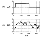
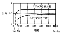
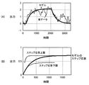
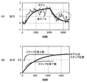
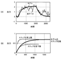
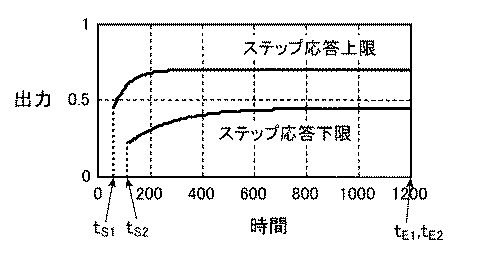
図5は、ゴミ焼却炉において、給塵機の速度をステップ状に変化させた場合における蒸気発生量の変化を示す図である。図5(A)は、給塵機の速度を示し、その横軸は、秒単位で表す経過時間を示し、その縦軸は、速度を示す。図5(B)は、蒸気発生量を示し、その横軸は、秒単位で表す経過時間を示し、その縦軸は、蒸気発生量を示す。図6は、制約条件としてのステップ応答の上限および下限を示す図である。図6の横軸は、秒単位で表す経過時間を示し、その縦軸は、蒸気発生量を示す。図7は、実施形態のモデリング装置でモデリングされたゴミ焼却炉のモデルにおけるステップ応答を説明するための図である。図7(A)は、給塵機の速度を示し、その太い実線は、モデル出力としての蒸気発生量を示し、その細い実線は、図5(B)に示す実績データとしての蒸気発生量を示す。図7(B)は、モデルのステップ応答(実線)、時刻tS1から時刻tE1までの間における上限のステップ応答Ymax(破線)および時刻tS2から時刻tE2までの間における下限のステップ応答Ymin(破線)が示されている。図8は、比較例としての従来の手法によりモデリングされたゴミ焼却炉のモデルにおけるステップ応答を説明するための図である。図8(A)は、給塵機の速度を示し、その太い実線は、モデル出力としての蒸気発生量を示し、その細い実線は、図5(B)に示す実績データとしての蒸気発生量を示す。図8(B)は、モデルのステップ応答(実線)、時刻tS1から時刻tE1までの間における上限のステップ応答Ymax(破線)および時刻tS2から時刻tE2までの間における下限のステップ応答Ymin(破線)が示されている。図9は、定常ゲインの制約条件を考慮した場合であって、実施形態のモデリング装置でモデリングされたゴミ焼却炉のモデルにおけるステップ応答を説明するための図である。図9(A)は、給塵機の速度を示し、その太い実線は、モデル出力としての蒸気発生量を示し、その細い実線は、図5(B)に示す実績データとしての蒸気発生量を示す。図9(B)は、モデルのステップ応答(実線)、時刻tS1から時刻tE1までの間における上限のステップ応答Ymax(破線)および時刻tS2から時刻tE2までの間における下限のステップ応答Ymin(破線)が示されている。 FIG. 5 is a diagram showing a change in the amount of steam generated when the speed of the dust feeder is changed stepwise in the refuse incinerator. FIG. 5A shows the speed of the dust feeder, the horizontal axis shows the elapsed time expressed in seconds, and the vertical axis shows the speed. FIG. 5B shows the steam generation amount, the horizontal axis shows the elapsed time expressed in seconds, and the vertical axis shows the steam generation amount. FIG. 6 is a diagram illustrating an upper limit and a lower limit of the step response as the constraint condition. The horizontal axis in FIG. 6 represents the elapsed time expressed in seconds, and the vertical axis represents the amount of steam generated. FIG. 7 is a diagram for explaining the step response in the model of the refuse incinerator modeled by the modeling apparatus of the embodiment. FIG. 7 (A) shows the speed of the dust feeder, its thick solid line shows the steam generation amount as a model output, and its thin solid line shows the steam generation amount as the actual data shown in FIG. 5 (B). Show. FIG. 7B shows a model step response (solid line), an upper limit step response Y max (broken line) between time t S1 and time t E1, and a lower limit step between time t S2 and time t E2. The response Y min (dashed line) is shown. FIG. 8 is a diagram for explaining a step response in a garbage incinerator model modeled by a conventional method as a comparative example. FIG. 8 (A) shows the speed of the dust feeder, its thick solid line shows the steam generation amount as a model output, and its thin solid line shows the steam generation amount as the actual data shown in FIG. 5 (B). Show. FIG. 8B shows a model step response (solid line), an upper limit step response Y max (broken line) between time t S1 and time t E1, and a lower limit step between time t S2 and time t E2. The response Y min (dashed line) is shown. FIG. 9 is a diagram for explaining the step response in the model of the refuse incinerator modeled by the modeling apparatus of the embodiment in consideration of the constraint condition of the steady gain. FIG. 9 (A) shows the speed of the dust feeder, its thick solid line shows the steam generation amount as a model output, and its thin solid line shows the steam generation amount as the actual data shown in FIG. 5 (B). Show. FIG. 9B shows a model step response (solid line), an upper limit step response Y max (broken line) between time t S1 and time t E1, and a lower limit step between time t S2 and time t E2. The response Y min (dashed line) is shown.
ゴミ焼却炉では、ゴミを焼却炉に供給する給塵機を入力とし、焼却炉で発生する蒸気発生量を出力とすると、図5(A)に示すように、給塵機の速度がステップ状に変化させた場合に、蒸気発生量は、図5(B)に示すように、基本的に、給塵機の稼動開始に伴って徐々に増大するとともに給塵機の稼動停止に伴って徐々に減少するプロファイルであるが、このプロファイルに外乱の影響によりノイズが重畳しており、その波形が大きく乱れている。この原因として、例えば、給塵機の速度が一定であっても給塵機によって実際に焼却炉に投入されるゴミの量は、必ずしも一定ではなく、変動し、蒸気発生量の外乱となると考えられる。しかしながら、実際に稼働中のゴミ焼却炉(生産設備やプラント等の制御対象)では、ゴミ焼却炉のモデル化のために実績入出力データを取得する実験機会や、ゴミ焼却炉に投入可能なゴミ量等が限定され、このようなノイズを含むデータしか取得できない場合もある。 In a garbage incinerator, when a dust feeder that supplies garbage to the incinerator is an input and the amount of steam generated in the incinerator is an output, as shown in FIG. As shown in FIG. 5 (B), the steam generation amount gradually increases with the start of operation of the dust supply unit and gradually with the stoppage of the operation of the dust supply unit. However, the noise is superimposed on the profile due to the influence of the disturbance, and the waveform is greatly disturbed. As a cause of this, for example, even if the speed of the dust feeder is constant, the amount of dust that is actually put into the incinerator by the dust feeder is not necessarily constant, and fluctuates, resulting in disturbance of the amount of generated steam. It is done. However, in actual waste incinerators (objects to be controlled for production facilities, plants, etc.), it is possible to obtain experimental input / output data to model waste incinerators, and garbage that can be thrown into waste incinerators. There are cases where the amount and the like are limited and only data including such noise can be acquired.
このようなゴミ焼却炉において、先験的情報として、時刻0において給塵機の速度を1単位だけステップ状に変化させる単位ステップ入力で変化させた場合に、蒸気発生量(ステップ応答)は、図6に示すように、時刻tS1から時刻tE1までの間における上限のステップ応答Ymax(破線、ステップ応答上限)と、時刻tS2から時刻tE2までの間における下限のステップ応答Ymin(破線、ステップ応答下限)との間に、存在することが分かっているものとする。このような先験的知識は、通常、ゴミ焼却炉を実際に稼動させるオペレータの経験や、ゴミ焼却炉の過去実績データ等が理解されるものであるが、ゴミ焼却炉の設計値等からも理解される場合もある。例えば、ゴミのカロリー(熱量)における変動範囲と、給塵機を1単位だけ変化させた場合におけるゴミの供給量変化に基づき、蒸気発生量の変化は、概略計算が可能である。
In such a garbage incinerator, as a priori information, when a unit step input is used to change the speed of the dust feeder in units of steps at
なお、このような推定計算は、このゴミ焼却炉のようなプラントだけでなく、種々の装置で可能である。例えば、リンク機構として、マニピュレータでは、入力トルクを1単位だけ変化させた場合に、アームの回転速度がどのくらいの時間でどのくらいの範囲で変化するか、その慣性や粘性等のパラメータから、時間応答の上限および下限が概略計算することができる。 Note that such estimation calculation can be performed not only by a plant such as the garbage incinerator but also by various devices. For example, in a manipulator as a link mechanism, when the input torque is changed by one unit, the time response is determined from the parameters such as how much time the arm rotation speed changes and how much the arm rotation speed changes. Upper and lower limits can be roughly calculated.
図5に示す実績データおよび図6に示す制約条件の下に、ゴミ燃焼炉を本実施形態のモデリング装置Sによってモデル化することによって作成されたゴミ燃焼炉のモデルにおけるステップ応答を図7に示す。この本実施形態のモデリング装置Sによるゴミ燃焼炉のモデルでは、そのステップ応答(蒸気発生量)は、図7(A)に示すように、図5(B)に示す実際の蒸気発生量の変化によく一致(フィッティング)しており、そして、図7(B)に示すように、ステップ応答の上限および下限の制約条件を満たしている。 FIG. 7 shows the step response in the model of the refuse combustion furnace created by modeling the refuse combustion furnace with the modeling apparatus S of the present embodiment under the actual data shown in FIG. 5 and the constraint condition shown in FIG. . In the garbage combustion furnace model by the modeling apparatus S of this embodiment, the step response (steam generation amount) is a change in the actual steam generation amount shown in FIG. 5 (B) as shown in FIG. 7 (A). (Fitting), and as shown in FIG. 7B, the upper and lower limit constraints of the step response are satisfied.
一方、図5に示す実績データおよび図6に示す制約条件の下に、ゴミ燃焼炉を従来の手法によってモデル化することによって作成されたゴミ燃焼炉のモデルにおけるステップ応答を図8に示す。この従来の手法によるゴミ燃焼炉のモデルでは、図7と比較すると、図7に示すステップ応答(蒸気発生量)ほど、実際の蒸気発生量の変化に一致していない。特に、図8(A)に破線の○で囲んだ外乱の大きな部分の実績出力データにモデルが合わせ込もうとされており、そのため、図8に示すステップ応答では、図7に示すステップ応答に較べて緩やかな立ち上がりとなってしまってしい、図7に示すステップ応答に較べてフィッティングの精度が落ちている。さらに、図8(B)に示すように、ステップ応答の上限および下限の制約条件を満たしていない部分がある。この結果、従来の手法では、再度、モデル化に使用するデータ区間を変更したり、フィルタリング等のデータの前処理を行ったり、あるいは、実績入出力データを取り直ししたり等、先験的情報の制約条件を満たすモデルが作成されるまで、試行錯誤的にモデル化作業を繰り返す必要がある。 On the other hand, FIG. 8 shows the step response in the model of the refuse combustion furnace created by modeling the refuse combustion furnace by the conventional method under the actual data shown in FIG. 5 and the constraint condition shown in FIG. Compared with FIG. 7, the conventional garbage combustion furnace model does not match the actual steam generation change as much as the step response (steam generation amount) shown in FIG. 7. In particular, the model is to be matched with the actual output data of the part with a large disturbance surrounded by a broken circle in FIG. 8A. Therefore, in the step response shown in FIG. 8, the step response shown in FIG. Compared to the step response shown in FIG. 7, the fitting accuracy is lowered, which is a gentle rise. Furthermore, as shown in FIG. 8B, there is a portion that does not satisfy the upper and lower limit constraints of the step response. As a result, in the conventional method, a priori information such as changing the data section used for modeling again, preprocessing data such as filtering, or re-accomplishing actual input / output data, etc. It is necessary to repeat modeling work by trial and error until a model that satisfies the constraint conditions is created.
しかしながら、本実施形態のモデリング装置Sは、図7と図8とを比較すると分かるように、このようなモデル化作業が軽減される。 However, the modeling apparatus S of the present embodiment reduces such modeling work as can be seen by comparing FIG. 7 and FIG.
ここで、上述のゴミ燃焼炉のモデル化では、図6(B)に示すように、ステップ応答が1200秒で略整定(飽和)していることから、制約条件の時間範囲をこの1200秒で区切っている。このため、1200秒を越える部分で、モデルの実用上問題の無いレベルであるが、ステップ応答がステップ応答の上限を越えてしまっている。そこで、厳密に、ステップ応答がステップ応答の上限および下限を逸脱しないようにするために、定常ゲインGの上下限値が制約条件とされてもよい。すなわち、上述したように、制約条件として、モデリング対象のシステムにおける定常ゲインがGmin以上かつGmax以下であることが、先験的知識として判明している場合に、a0×Gmin≦b0≦a0×Gmaxを満たすように、i番目の粒子p(i,0)の初期値がランダムに設定され、そして、a0×Gmin≦b0≦a0×Gmaxを満たすように、更新される。このような制約条件を課すことにより、ステップ応答(蒸気発生量)は、図9(A)に示すように、図5(B)に示す実際の蒸気発生量の変化によく一致(フィッティング)しているだけでなく、図9(B)に示すように、1200秒を越えた範囲も含めて、ステップ応答の上限および下限の制約条件を満たしている。 Here, in the above-described modeling of the garbage combustion furnace, as shown in FIG. 6B, the step response is substantially settled (saturated) in 1200 seconds, so the time range of the constraint condition is 1200 seconds. It is separated. For this reason, the step response exceeds the upper limit of the step response, although it is at a level where there is no problem in practical use of the model in the portion exceeding 1200 seconds. Therefore, strictly, the upper and lower limit values of the steady gain G may be set as a constraint condition so that the step response does not deviate from the upper limit and the lower limit of the step response. That is, as described above, when it is known as a priori knowledge that the steady-state gain in the system to be modeled is G min or more and G max or less as a constraint condition, a 0 × G min ≦ b so as to satisfy 0 ≦ a 0 × G max, the initial value of i-th particle p (i, 0) is set at random, and, to satisfy a 0 × G min ≦ b 0 ≦ a 0 × G max It will be updated. By imposing such constraint conditions, the step response (steam generation amount) matches well with the actual steam generation change shown in FIG. 5B (fitting) as shown in FIG. 9A. In addition, as shown in FIG. 9B, the upper limit and the lower limit of the step response are satisfied, including the range exceeding 1200 seconds.
なお、上述では、給塵機の速度を入力とし、蒸気発生量を出力としたが、入出力の関係は、これに限定されるものではなく、種々の関係であって良い。例えば、入力としては、押込空気量や、空気供給量や、バーナ油量や、蒸気弁開度や、触媒投入量等が挙げられ、出力としては、砂層温度や、炉内温度や、ボイラドラム圧力や、炉内圧力や、酸素濃度や、一酸化炭素濃度や、NOx濃度等が挙げられる。 In the above description, the speed of the dust feeder is input and the steam generation amount is output. However, the input / output relationship is not limited to this, and may be various relationships. For example, the input includes the amount of forced air, the amount of air supplied, the amount of burner oil, the opening of the steam valve, the amount of catalyst input, and the output includes the sand layer temperature, furnace temperature, boiler drum, etc. Examples include pressure, furnace pressure, oxygen concentration, carbon monoxide concentration, and NOx concentration.
本実施形態のモデリング装置Sの適用例としてゴミ焼却炉のモデル化について説明したが、本実施形態のモデリング装置Sは、操作量を入力とするとともに制御量を出力とすることで、様々な制御対象のモデル化に適用可能である。本実施形態のモデリング装置Sは、例えば、圧延機のモデル化に適用可能であり、例えば、圧下位置やロール速度等を入力とし、スタンド間張力や板幅・板厚等を出力とすることができる。また例えば、本実施形態のモデリング装置Sは、マニピュレータのモデル化に適用可能であり、トルク等を入力とし、アーム速度や位置等を出力とすることができる。 Although the modeling of the refuse incinerator has been described as an application example of the modeling apparatus S of the present embodiment, the modeling apparatus S of the present embodiment can perform various controls by using the operation amount as an input and the control amount as an output. It can be applied to target modeling. The modeling apparatus S of the present embodiment can be applied to, for example, modeling of a rolling mill, for example, by inputting a rolling position, a roll speed, and the like, and outputting an interstand tension, a plate width, a plate thickness, and the like. it can. Further, for example, the modeling apparatus S of the present embodiment can be applied to the modeling of a manipulator, and can input torque and the like, and can output arm speed and position and the like.
なお、上述の実施形態において、モデルのパラメータにおける初期値を設定してから前記モデルのパラメータの値を求める最適化方法によって前記モデルのパラメータの値を求める場合に、前記初期値自体を前記モデルのパラメータとして扱うように、モデリング装置Sが構成されてもよい。一般に、モデルのパラメータにおける初期値を設定してから前記モデルのパラメータの値を求める最適化方法では、この最適化手法によって構築されるシステムのモデルの精度は、初期値に左右されることが多い。このため、このように構成されることによって、この初期値自体も未知パラメータとして取り扱われるので、初期値に左右されることなく、システムのモデルをより高精度に構築することが可能となる。 In the above-described embodiment, when the parameter value of the model is obtained by an optimization method for obtaining the value of the model parameter after setting the initial value of the model parameter, the initial value itself is set to the value of the model. The modeling apparatus S may be configured to handle it as a parameter. In general, in an optimization method in which an initial value in a model parameter is set and then the value of the model parameter is obtained, the accuracy of the model of the system constructed by this optimization method is often influenced by the initial value. . For this reason, since the initial value itself is also handled as an unknown parameter, the system model can be constructed with higher accuracy without being influenced by the initial value.
例えば、上述の1入力1出力系のシステムの場合において、初期状態が0(ゼロベクトル)であることを前提にモデルが構築されている。すなわち、モデリング対象のシステムが整定している状態(平衡状態)において入力データが印加されたものと見なされており、モデルの構築に用いた例えば実績入出力データ等の入出力データは、初期状態が0であるとされている。 For example, in the above-described one-input one-output system, the model is constructed on the assumption that the initial state is 0 (zero vector). That is, it is considered that the input data is applied when the system to be modeled is in a set state (equilibrium state), and the input / output data such as the actual input / output data used for the model construction is the initial state. Is assumed to be 0.
式4において、状態x(t)の挙動は、一般に、式11となることが知られている。
x(t)=Φ(t)x(0)+∫Φ(t−τ)Bu(τ)dτ ・・・(11)
ここで、積分区間は、0からtまでであり、Φ(t)は、遷移マトリックスと呼ばれ、式12によって表される。
Φ(t)=exp(At)
=I+At+A2t2/2!+A3t3/3!+・・・ ・・・(12)
In
x (t) = Φ (t) x (0) + ∫Φ (t−τ) Bu (τ) dτ (11)
Here, the integration interval is from 0 to t, and Φ (t) is referred to as a transition matrix and is expressed by
Φ (t) = exp (At)
= I + At + A 2 t 2/2! + A 3 t 3/3! + ... (12)
この式11で表される状態x(t)を式4−2に代入すると、式13が得られ、初期状態x(0)=0でなければ、出力ym(t)は、初期状態x(0)の影響を受けることが分かる。
ym(t)=CΦ(t)x(0)+C∫Φ(t−τ)Bu(τ)dτ+Du(t) ・・・(13)
By substituting the state x (t) represented by
y m (t) = CΦ (t) x (0) + C∫Φ (t−τ) Bu (τ) dτ + Du (t) (13)
モデルを構築するための入出力データを得る実際の実験において、例えばマニピュレータ等の機械系のシステムでは、システムが静止した状態から実験を開始することが可能であり、この場合では初期状態を0と見なせるが、例えばゴミ燃焼炉や化学プラント等のプラント系のシステムでは、稼動中に実験を行わなければならず、状態が絶えず変動しており、通常、初期状態が0とはならない。 In an actual experiment for obtaining input / output data for constructing a model, for example, in a mechanical system such as a manipulator, the experiment can be started from a stationary state. In this case, the initial state is set to 0. Although it can be considered, for example, in a plant system such as a garbage combustion furnace or a chemical plant, an experiment must be performed during operation, the state is constantly changing, and the initial state is usually not zero.
このため、上述のように、初期状態自体もパラメータとして扱い、モデルを構築することが好ましい。 For this reason, as described above, it is preferable to handle the initial state itself as a parameter and construct a model.
より具体的には、例えば、上述の1入力1出力系のシステムの場合において、式4および式5、あるいは、式6では、モデリング対象のシステムのモデル次数が2次であるから、初期状態x(0)=[x1 x2]Tとおくことができる。このため、P個のうちのi番目の粒子p(i,k)は、式7に代えて、式14によって表現されることになる。
p(i,k)=[a0 a1 b0 b1 x1 x2]T ・・・(14)
More specifically, for example, in the case of the above-described system of one input and one output system, since the model order of the system to be modeled is second order in
p (i, k) = [a 0 a 1 b 0 b 1 x 1 x 2 ] T (14)
また、この場合におけるi番目の粒子pの移動速度v(i,0)の初期値は、v(i,0)=[0 0 0 0 0 0]Tに設定される。 In this case, the initial value of the moving speed v (i, 0) of the i-th particle p is set to v (i, 0) = [0 0 0 0 0 0] T.
このような初期値の設定を行って、以下、上述と同様の処理によってシステムのモデルが構築される。 By setting such initial values, a system model is constructed by the same processing as described above.
また、上述の実施形態において、予め決められた所定の最適化方法によって前記モデルのパラメータの値を求め、この求めた前記モデルのパラメータの値をPSO法の初期値に加えて用いるように、モデリング装置Sが構成されてもよい。前記所定の最適化方法として、PSO法、最小二乗法および部分空間法等の各種の最適化手法が挙げられる。なお、最小二乗法や部分空間法が用いられる場合には、離散時間で一旦状態空間モデル式や伝達関数モデル式を求め、これを連続時間のモデルに変換される。また、PSO法を用いる場合では、評価関数のみを単に最小化するモデルが求められても良いし、その際に、Ji=||W(Yi−Ydata)||<ε(εは所定の閾値である)となる粒子pを保存しておいても良い。このPSO法を用いる場合では、初期値の決定およびモデルの構築の2回、PSO法が使われることになる。一般に、モデルのパラメータにおける初期値を設定してから前記モデルのパラメータの値を求める最適化方法では、この最適化手法によって構築されるシステムのモデルの精度は、初期値に左右されることが多い。このため、PSO法による場合でもランダムに振る範囲が試行錯誤によって決定される。このため、この試行錯誤の手間を軽減し、最適なモデルを求めるためには、最初のモデルが入出力データにある程度フィッティングしていることが望ましい。この構成では、PSOに用いる初期値として、予め決められた所定の最適化方法によって求められたモデルのパラメータの値も用いるので、より真に近い値を含む初期値からPSO法の演算処理を開始することができるから、不必要な探索を行うことなく、システムのモデルをより高精度に構築することができる。 In the above-described embodiment, the model parameter value is obtained by a predetermined optimization method determined in advance, and the obtained model parameter value is used in addition to the initial value of the PSO method. The device S may be configured. Examples of the predetermined optimization method include various optimization methods such as PSO method, least square method, and subspace method. When the least square method or the subspace method is used, a state space model expression or a transfer function model expression is obtained once in discrete time, and converted into a continuous time model. In the case of using the PSO method, a model that simply minimizes only the evaluation function may be obtained. In this case, J i = || W (Y i -Y data ) || <ε (ε is You may preserve | save the particle | grain p used as the predetermined threshold). In the case of using this PSO method, the PSO method is used twice, that is, determination of an initial value and construction of a model. In general, in an optimization method in which an initial value in a model parameter is set and then the value of the model parameter is obtained, the accuracy of the model of the system constructed by this optimization method is often influenced by the initial value. . For this reason, even in the case of the PSO method, the range of random shaking is determined by trial and error. For this reason, in order to reduce the labor of trial and error and obtain an optimum model, it is desirable that the first model is fitted to the input / output data to some extent. In this configuration, since the parameter value of the model obtained by a predetermined optimization method determined in advance is also used as the initial value used for the PSO, the calculation processing of the PSO method is started from the initial value including a value closer to the true value. Therefore, the system model can be constructed with higher accuracy without performing unnecessary search.
本発明を表現するために、上述において図面を参照しながら実施形態を通して本発明を適切且つ十分に説明したが、当業者であれば上述の実施形態を変更および/または改良することは容易に為し得ることであると認識すべきである。したがって、当業者が実施する変更形態または改良形態が、請求の範囲に記載された請求項の権利範囲を離脱するレベルのものでない限り、当該変更形態または当該改良形態は、当該請求項の権利範囲に包括されると解釈される。 In order to express the present invention, the present invention has been properly and fully described through the embodiments with reference to the drawings. However, those skilled in the art can easily change and / or improve the above-described embodiments. It should be recognized that this is possible. Therefore, unless the modifications or improvements implemented by those skilled in the art are at a level that departs from the scope of the claims recited in the claims, the modifications or improvements are not covered by the claims. To be construed as inclusive.
S モデリング装置
1 演算部
2 入力設定部
4 記憶部
11 モデル出力演算部
12 制約条件評価部
13 評価演算部
14 モデル更新決定部
21 制約条件入力設定部
22 モデル次数同定パラメータ入力設定部
23 最適化計算パラメータ入力設定部
24 評価関数入力設定部
41 制約条件記憶部
42 モデル次数同定パラメータ記憶部
43 最適化計算パラメータ記憶部
44 評価関数記憶部
45 モデル出力等記憶部
46 実績データ記憶部
Claims (8)
前記モデルは、連続した時間と見なされる時間変数を含む数式であり、
予め得られている前記システムに関する先験的情報を制約条件として設定する制約条件設定部と、
所定の入力データを実績入力データとして前記システムに入力した場合に前記システムから出力された実績出力データと、前記実績入力データを前記モデルに入力した場合に前記モデルから出力されたモデル出力データとの誤差を評価する評価関数の評価結果を求める評価演算部と、
前記制約条件設定部で設定された制約条件を満たし、かつ、前記評価演算部で演算された評価結果が最良となるように、前記モデルのパラメータの値を求めるモデル演算部とを備えること
を特徴とするモデリング装置。 In a modeling device for building a model of a system by determining values of parameters of the model,
The model is a mathematical formula that includes a time variable that is considered a continuous time;
A constraint condition setting unit that sets a priori information about the system obtained in advance as a constraint condition;
The actual output data output from the system when predetermined input data is input to the system as actual input data, and the model output data output from the model when the actual input data is input to the model. An evaluation calculation unit for obtaining an evaluation result of an evaluation function for evaluating an error;
A model calculation unit that satisfies the constraint condition set by the constraint condition setting unit and obtains the parameter value of the model so that the evaluation result calculated by the evaluation calculation unit is the best. Modeling equipment.
を特徴とする請求項1に記載のモデリング装置。 The modeling apparatus according to claim 1, wherein the a priori information is at least one of an upper limit value and a lower limit value related to a steady gain in the system.
前記重みは、その値が大きいほど前記評価結果に大きく影響を与えるものである場合に、前記重みの値は、所定の閾値以上のノイズを含む実績出力データに対応する区間に対し、前記区間を除く他の区間よりも相対的に小さくなるように設定されること
を特徴とする請求項1または請求項2に記載のモデリング装置。 The evaluation function has a weight for weighting an error between the actual output data and the model output data,
In the case where the weight has a greater influence on the evaluation result as the value is larger, the weight value is set to the interval corresponding to the actual output data including noise of a predetermined threshold value or more. The modeling apparatus according to claim 1, wherein the modeling apparatus is set so as to be relatively smaller than other sections excluding the section.
を特徴とする請求項1ないし請求項3の何れか1項に記載のモデリング装置。 When the model calculation unit obtains the value of the model parameter by an optimization method that obtains the value of the model parameter after setting an initial value of the parameter of the model, the model operation unit converts the initial value itself into the parameter of the model The modeling apparatus according to any one of claims 1 to 3, wherein the modeling apparatus is handled as:
を特徴とする請求項1ないし請求項4のいずれか1項に記載のモデリング装置。 The modeling apparatus according to any one of claims 1 to 4, wherein the model calculation unit obtains a value of a parameter of the model by a Particle Swarm Optimization Method.
を特徴とする請求項5に記載のモデリング装置。 6. The model calculation unit according to claim 5, wherein the model calculation unit obtains a parameter value of the model by a predetermined optimization method, and adds the obtained parameter value of the model to an initial value of the Particle Swarm Optimization Method. The modeling device described.
を特徴とする請求項5または請求項6に記載のモデリング装置。 The model computing unit, when performing an update by the Particle Swarm Optimization Method, at least one of a sign of a steady gain, a steady gain range, information on the stability of the system, and information on an unstable zero point of the system The modeling apparatus according to claim 5 or 6, wherein one is used.
前記モデルは、連続した時間と見なされる時間変数を含む数式であり、
予め得られている前記システムに関する先験的情報を制約条件として設定する制約条件設定ステップと、
所定の入力データを実績入力データとして前記システムに入力した場合に前記システムから出力された実績出力データと、前記実績入力データを前記モデルに入力した場合に前記モデルから出力されたモデル出力データとの誤差を評価する評価関数の評価結果を求める評価演算ステップと、
前記制約条件設定ステップで設定された制約条件を満たし、かつ、前記評価演算ステップで演算された評価結果が最良となるように、前記モデルのパラメータの値を求めるモデル演算ステップとを備えること
を特徴とするモデリング方法。 In a modeling method for building a model of a system by determining values of parameters of the model,
The model is a mathematical formula that includes a time variable that is considered a continuous time;
A constraint condition setting step for setting a priori information on the system obtained in advance as a constraint condition;
The actual output data output from the system when predetermined input data is input to the system as actual input data, and the model output data output from the model when the actual input data is input to the model. An evaluation calculation step for obtaining an evaluation result of an evaluation function for evaluating an error;
A model calculation step for obtaining a parameter value of the model so that the constraint condition set in the constraint condition setting step is satisfied and the evaluation result calculated in the evaluation calculation step is the best. Modeling method.
Priority Applications (1)
| Application Number | Priority Date | Filing Date | Title |
|---|---|---|---|
| JP2011053436A JP5698572B2 (en) | 2011-03-10 | 2011-03-10 | Modeling apparatus and method |
Applications Claiming Priority (1)
| Application Number | Priority Date | Filing Date | Title |
|---|---|---|---|
| JP2011053436A JP5698572B2 (en) | 2011-03-10 | 2011-03-10 | Modeling apparatus and method |
Publications (2)
| Publication Number | Publication Date |
|---|---|
| JP2012190274A true JP2012190274A (en) | 2012-10-04 |
| JP5698572B2 JP5698572B2 (en) | 2015-04-08 |
Family
ID=47083351
Family Applications (1)
| Application Number | Title | Priority Date | Filing Date |
|---|---|---|---|
| JP2011053436A Active JP5698572B2 (en) | 2011-03-10 | 2011-03-10 | Modeling apparatus and method |
Country Status (1)
| Country | Link |
|---|---|
| JP (1) | JP5698572B2 (en) |
Cited By (5)
| Publication number | Priority date | Publication date | Assignee | Title |
|---|---|---|---|---|
| KR20160145492A (en) * | 2015-06-10 | 2016-12-20 | 도쿄엘렉트론가부시키가이샤 | Heat treatment apparatus, regulation method of heat treatment apparatus, and program |
| KR20180056942A (en) * | 2016-11-21 | 2018-05-30 | 서울대학교산학협력단 | Robust parameter estimating method for crash hotspot identification based on traffic accident frequency simulation |
| CN109343345A (en) * | 2018-09-28 | 2019-02-15 | 江南大学 | Polynomial interpolation trajectory planning method for manipulator based on QPSO algorithm |
| JP2020057238A (en) * | 2018-10-03 | 2020-04-09 | 株式会社日立製作所 | Control device and control method |
| WO2024031887A1 (en) * | 2022-08-09 | 2024-02-15 | 浙江中控技术股份有限公司 | Model identification method and apparatus for industrial control system, device and storage medium |
Families Citing this family (1)
| Publication number | Priority date | Publication date | Assignee | Title |
|---|---|---|---|---|
| JP7013296B2 (en) * | 2018-03-22 | 2022-01-31 | 三菱重工業株式会社 | Parameter identification device and its method and program |
Citations (7)
| Publication number | Priority date | Publication date | Assignee | Title |
|---|---|---|---|---|
| JPH07121505A (en) * | 1993-10-27 | 1995-05-12 | Kawasaki Steel Corp | Simulation model optimization method |
| JPH10198402A (en) * | 1997-01-09 | 1998-07-31 | Nippon Steel Corp | Method and apparatus for identifying initial values of learning parameters |
| JP2004164426A (en) * | 2002-11-14 | 2004-06-10 | Fuji Electric Fa Components & Systems Co Ltd | Output control method, output control device, and output control program |
| JP2005211963A (en) * | 2004-01-30 | 2005-08-11 | Sumitomo Metal Ind Ltd | Method for correcting model parameters in steel process and method for producing hot-rolled steel sheet using the method |
| JP2005339011A (en) * | 2004-05-25 | 2005-12-08 | Fujitsu Ltd | Servo control method, servo control system, and disk device |
| JP2007186734A (en) * | 2006-01-11 | 2007-07-26 | Kobe Steel Ltd | Method and instrument for predicting molten steel temperature |
| JP2008287343A (en) * | 2007-05-15 | 2008-11-27 | Kobe Steel Ltd | Model parameter estimating arithmetic unit and method, model parameter estimating arithmetic processing program, and recording medium recording the same |
-
2011
- 2011-03-10 JP JP2011053436A patent/JP5698572B2/en active Active
Patent Citations (7)
| Publication number | Priority date | Publication date | Assignee | Title |
|---|---|---|---|---|
| JPH07121505A (en) * | 1993-10-27 | 1995-05-12 | Kawasaki Steel Corp | Simulation model optimization method |
| JPH10198402A (en) * | 1997-01-09 | 1998-07-31 | Nippon Steel Corp | Method and apparatus for identifying initial values of learning parameters |
| JP2004164426A (en) * | 2002-11-14 | 2004-06-10 | Fuji Electric Fa Components & Systems Co Ltd | Output control method, output control device, and output control program |
| JP2005211963A (en) * | 2004-01-30 | 2005-08-11 | Sumitomo Metal Ind Ltd | Method for correcting model parameters in steel process and method for producing hot-rolled steel sheet using the method |
| JP2005339011A (en) * | 2004-05-25 | 2005-12-08 | Fujitsu Ltd | Servo control method, servo control system, and disk device |
| JP2007186734A (en) * | 2006-01-11 | 2007-07-26 | Kobe Steel Ltd | Method and instrument for predicting molten steel temperature |
| JP2008287343A (en) * | 2007-05-15 | 2008-11-27 | Kobe Steel Ltd | Model parameter estimating arithmetic unit and method, model parameter estimating arithmetic processing program, and recording medium recording the same |
Cited By (9)
| Publication number | Priority date | Publication date | Assignee | Title |
|---|---|---|---|---|
| KR20160145492A (en) * | 2015-06-10 | 2016-12-20 | 도쿄엘렉트론가부시키가이샤 | Heat treatment apparatus, regulation method of heat treatment apparatus, and program |
| KR102103618B1 (en) * | 2015-06-10 | 2020-04-22 | 도쿄엘렉트론가부시키가이샤 | Heat treatment apparatus, regulation method of heat treatment apparatus, and program |
| US10641553B2 (en) | 2015-06-10 | 2020-05-05 | Tokyo Electron Limited | Heat treatment apparatus, regulation method of heat treatment apparatus, and program |
| KR20180056942A (en) * | 2016-11-21 | 2018-05-30 | 서울대학교산학협력단 | Robust parameter estimating method for crash hotspot identification based on traffic accident frequency simulation |
| KR101911606B1 (en) | 2016-11-21 | 2018-10-24 | 서울대학교산학협력단 | Robust parameter estimating method for crash hotspot identification based on traffic accident frequency simulation |
| CN109343345A (en) * | 2018-09-28 | 2019-02-15 | 江南大学 | Polynomial interpolation trajectory planning method for manipulator based on QPSO algorithm |
| CN109343345B (en) * | 2018-09-28 | 2021-12-03 | 江南大学 | Mechanical arm polynomial interpolation track planning method based on QPSO algorithm |
| JP2020057238A (en) * | 2018-10-03 | 2020-04-09 | 株式会社日立製作所 | Control device and control method |
| WO2024031887A1 (en) * | 2022-08-09 | 2024-02-15 | 浙江中控技术股份有限公司 | Model identification method and apparatus for industrial control system, device and storage medium |
Also Published As
| Publication number | Publication date |
|---|---|
| JP5698572B2 (en) | 2015-04-08 |
Similar Documents
| Publication | Publication Date | Title |
|---|---|---|
| JP5698572B2 (en) | Modeling apparatus and method | |
| CN114329802B (en) | Probabilistic fatigue and mixing limit assessment and visualization method for airfoils | |
| JP7064356B2 (en) | Future state estimation device and future state estimation method | |
| US11371696B2 (en) | System and method for configuring boiler combustion model | |
| CN1866286A (en) | Method and system for performing multi-objective predictive modeling, monitoring, and update for an asset | |
| EP3580619B1 (en) | Method and apparatus for robust reduction of shape error in laser powder deposition based additive manufacturing process due to uncertainty | |
| JP2007500379A (en) | Software optimization device for intelligent control system | |
| EP1717735A2 (en) | Method and system for performing model-based multi-objective asset optimization and decision-making | |
| CN113723615A (en) | Training method and device of deep reinforcement learning model based on hyper-parametric optimization | |
| CN111433689B (en) | Generation of control systems for target systems | |
| Zolfagharian et al. | Unwanted noise and vibration control using finite element analysis and artificial intelligence | |
| CN101566829A (en) | Method for computer-aided open loop and/or closed loop control of a technical system | |
| JP2004178492A (en) | Plant simulation method using enhanced learning method | |
| Bernini et al. | A few lessons learned in reinforcement learning for quadcopter attitude control | |
| US20200218232A1 (en) | System and method for fluid flow control design | |
| CN119356124A (en) | Control method and system for assembly equipment | |
| Yaseen et al. | Fast and accurate reduced-order modeling of a MOOSE-based additive manufacturing model with operator learning | |
| CN116894407A (en) | Elbow pneumatic conveying erosion prediction method and system based on digital twin | |
| US20070135938A1 (en) | Methods and systems for predictive modeling using a committee of models | |
| JP2023074434A (en) | Future state estimating device | |
| EP3945375B1 (en) | Machine controller and methods for configuring and using the machine controller | |
| CN111356959B (en) | Method for computer-aided control of a technical system | |
| WO2022270056A1 (en) | Prediction system, information processing device, and information processing program | |
| JP6999207B1 (en) | Data analysis method, data analysis device, and data analysis program | |
| CA3125466C (en) | Probabilistic fatigue and blend limit assessment and visualization methods for airfoils |
Legal Events
| Date | Code | Title | Description |
|---|---|---|---|
| A621 | Written request for application examination |
Free format text: JAPANESE INTERMEDIATE CODE: A621 Effective date: 20130902 |
|
| A977 | Report on retrieval |
Free format text: JAPANESE INTERMEDIATE CODE: A971007 Effective date: 20140521 |
|
| A131 | Notification of reasons for refusal |
Free format text: JAPANESE INTERMEDIATE CODE: A131 Effective date: 20140527 |
|
| A521 | Written amendment |
Free format text: JAPANESE INTERMEDIATE CODE: A523 Effective date: 20140728 |
|
| TRDD | Decision of grant or rejection written | ||
| A01 | Written decision to grant a patent or to grant a registration (utility model) |
Free format text: JAPANESE INTERMEDIATE CODE: A01 Effective date: 20150203 |
|
| A61 | First payment of annual fees (during grant procedure) |
Free format text: JAPANESE INTERMEDIATE CODE: A61 Effective date: 20150213 |
|
| R150 | Certificate of patent or registration of utility model |
Ref document number: 5698572 Country of ref document: JP Free format text: JAPANESE INTERMEDIATE CODE: R150 |