JP2012190509A - Optical information medium, optical information recording and reproducing device and optical information recording and reproducing method - Google Patents
Optical information medium, optical information recording and reproducing device and optical information recording and reproducing method Download PDFInfo
- Publication number
- JP2012190509A JP2012190509A JP2011053707A JP2011053707A JP2012190509A JP 2012190509 A JP2012190509 A JP 2012190509A JP 2011053707 A JP2011053707 A JP 2011053707A JP 2011053707 A JP2011053707 A JP 2011053707A JP 2012190509 A JP2012190509 A JP 2012190509A
- Authority
- JP
- Japan
- Prior art keywords
- bca
- optical information
- data
- level
- reflection side
- Prior art date
- Legal status (The legal status is an assumption and is not a legal conclusion. Google has not performed a legal analysis and makes no representation as to the accuracy of the status listed.)
- Pending
Links
Images











Classifications
-
- G—PHYSICS
- G11—INFORMATION STORAGE
- G11B—INFORMATION STORAGE BASED ON RELATIVE MOVEMENT BETWEEN RECORD CARRIER AND TRANSDUCER
- G11B7/00—Recording or reproducing by optical means, e.g. recording using a thermal beam of optical radiation by modifying optical properties or the physical structure, reproducing using an optical beam at lower power by sensing optical properties; Record carriers therefor
- G11B7/007—Arrangement of the information on the record carrier, e.g. form of tracks, actual track shape, e.g. wobbled, or cross-section, e.g. v-shaped; Sequential information structures, e.g. sectoring or header formats within a track
- G11B7/00736—Auxiliary data, e.g. lead-in, lead-out, Power Calibration Area [PCA], Burst Cutting Area [BCA], control information
-
- G—PHYSICS
- G11—INFORMATION STORAGE
- G11B—INFORMATION STORAGE BASED ON RELATIVE MOVEMENT BETWEEN RECORD CARRIER AND TRANSDUCER
- G11B20/00—Signal processing not specific to the method of recording or reproducing; Circuits therefor
- G11B20/10—Digital recording or reproducing
- G11B20/12—Formatting, e.g. arrangement of data block or words on the record carriers
- G11B20/1217—Formatting, e.g. arrangement of data block or words on the record carriers on discs
-
- G—PHYSICS
- G11—INFORMATION STORAGE
- G11B—INFORMATION STORAGE BASED ON RELATIVE MOVEMENT BETWEEN RECORD CARRIER AND TRANSDUCER
- G11B7/00—Recording or reproducing by optical means, e.g. recording using a thermal beam of optical radiation by modifying optical properties or the physical structure, reproducing using an optical beam at lower power by sensing optical properties; Record carriers therefor
- G11B7/24—Record carriers characterised by shape, structure or physical properties, or by the selection of the material
- G11B7/24094—Indication parts or information parts for identification
-
- G—PHYSICS
- G11—INFORMATION STORAGE
- G11B—INFORMATION STORAGE BASED ON RELATIVE MOVEMENT BETWEEN RECORD CARRIER AND TRANSDUCER
- G11B20/00—Signal processing not specific to the method of recording or reproducing; Circuits therefor
- G11B20/00086—Circuits for prevention of unauthorised reproduction or copying, e.g. piracy
- G11B20/0021—Circuits for prevention of unauthorised reproduction or copying, e.g. piracy involving encryption or decryption of contents recorded on or reproduced from a record carrier
- G11B20/00217—Circuits for prevention of unauthorised reproduction or copying, e.g. piracy involving encryption or decryption of contents recorded on or reproduced from a record carrier the cryptographic key used for encryption and/or decryption of contents recorded on or reproduced from the record carrier being read from a specific source
- G11B20/00253—Circuits for prevention of unauthorised reproduction or copying, e.g. piracy involving encryption or decryption of contents recorded on or reproduced from a record carrier the cryptographic key used for encryption and/or decryption of contents recorded on or reproduced from the record carrier being read from a specific source wherein the key is stored on the record carrier
- G11B20/0026—Circuits for prevention of unauthorised reproduction or copying, e.g. piracy involving encryption or decryption of contents recorded on or reproduced from a record carrier the cryptographic key used for encryption and/or decryption of contents recorded on or reproduced from the record carrier being read from a specific source wherein the key is stored on the record carrier the key being stored as a barcode
- G11B20/00268—Circuits for prevention of unauthorised reproduction or copying, e.g. piracy involving encryption or decryption of contents recorded on or reproduced from a record carrier the cryptographic key used for encryption and/or decryption of contents recorded on or reproduced from the record carrier being read from a specific source wherein the key is stored on the record carrier the key being stored as a barcode said barcode being recorded in a burst cutting area [BCA]
-
- G—PHYSICS
- G11—INFORMATION STORAGE
- G11B—INFORMATION STORAGE BASED ON RELATIVE MOVEMENT BETWEEN RECORD CARRIER AND TRANSDUCER
- G11B20/00—Signal processing not specific to the method of recording or reproducing; Circuits therefor
- G11B20/10—Digital recording or reproducing
- G11B20/14—Digital recording or reproducing using self-clocking codes
- G11B20/1403—Digital recording or reproducing using self-clocking codes characterised by the use of two levels
-
- G—PHYSICS
- G11—INFORMATION STORAGE
- G11B—INFORMATION STORAGE BASED ON RELATIVE MOVEMENT BETWEEN RECORD CARRIER AND TRANSDUCER
- G11B20/00—Signal processing not specific to the method of recording or reproducing; Circuits therefor
- G11B20/10—Digital recording or reproducing
- G11B20/14—Digital recording or reproducing using self-clocking codes
- G11B20/1403—Digital recording or reproducing using self-clocking codes characterised by the use of two levels
- G11B20/1423—Code representation depending on subsequent bits, e.g. delay modulation, double density code, Miller code
- G11B20/1426—Code representation depending on subsequent bits, e.g. delay modulation, double density code, Miller code conversion to or from block codes or representations thereof
-
- G—PHYSICS
- G11—INFORMATION STORAGE
- G11B—INFORMATION STORAGE BASED ON RELATIVE MOVEMENT BETWEEN RECORD CARRIER AND TRANSDUCER
- G11B20/00—Signal processing not specific to the method of recording or reproducing; Circuits therefor
- G11B20/10—Digital recording or reproducing
- G11B20/12—Formatting, e.g. arrangement of data block or words on the record carriers
- G11B20/1217—Formatting, e.g. arrangement of data block or words on the record carriers on discs
- G11B2020/1218—Formatting, e.g. arrangement of data block or words on the record carriers on discs wherein the formatting concerns a specific area of the disc
- G11B2020/122—Burst cutting area [BCA]
-
- G—PHYSICS
- G11—INFORMATION STORAGE
- G11B—INFORMATION STORAGE BASED ON RELATIVE MOVEMENT BETWEEN RECORD CARRIER AND TRANSDUCER
- G11B2220/00—Record carriers by type
- G11B2220/20—Disc-shaped record carriers
- G11B2220/25—Disc-shaped record carriers characterised in that the disc is based on a specific recording technology
- G11B2220/2537—Optical discs
- G11B2220/2541—Blu-ray discs; Blue laser DVR discs
-
- G—PHYSICS
- G11—INFORMATION STORAGE
- G11B—INFORMATION STORAGE BASED ON RELATIVE MOVEMENT BETWEEN RECORD CARRIER AND TRANSDUCER
- G11B7/00—Recording or reproducing by optical means, e.g. recording using a thermal beam of optical radiation by modifying optical properties or the physical structure, reproducing using an optical beam at lower power by sensing optical properties; Record carriers therefor
- G11B7/004—Recording, reproducing or erasing methods; Read, write or erase circuits therefor
- G11B7/005—Reproducing
- G11B7/0053—Reproducing non-user data, e.g. wobbled address, prepits, BCA
Landscapes
- Engineering & Computer Science (AREA)
- Signal Processing (AREA)
- Optical Recording Or Reproduction (AREA)
- Optical Record Carriers And Manufacture Thereof (AREA)
Abstract
Description
本発明は、光情報媒体、光情報記録再生装置及び光情報記録再生方法に関する。 The present invention relates to an optical information medium, an optical information recording / reproducing apparatus, and an optical information recording / reproducing method.
従来の光ディスク、例えばBlu−ray Disc(BD)などにおいては、ユーザデータ領域に格納されているデータの管理及びその著作権の保護のために、光ディスクの内周にはBurst Cutting Area(BCA)が設けられている。BCAに関する技術としては、例えば特許文献1、特許文献2などに開示されている。
In a conventional optical disc such as a Blu-ray Disc (BD), a Burst Cutting Area (BCA) is provided on the inner periphery of the optical disc in order to manage the data stored in the user data area and protect its copyright. Is provided. For example,
BCAデータの書き込みは従来、ユーザデータ領域の形成後にBCAカッター等によって行われていた。しかし、このような方法では、ディスク製造工程にBCA形成用に個別の工程を設けざるを得ず、ディスクの生産工数、更には製造コストの観点で、ディスク生産者の負荷が大きい。 Conventionally, the BCA data is written by a BCA cutter or the like after the user data area is formed. However, in such a method, an individual process for forming the BCA must be provided in the disk manufacturing process, and the load on the disk producer is large from the viewpoint of manufacturing man-hours and manufacturing costs.
上記課題は特許請求の範囲に記載の発明により解決される。 The above problems are solved by the invention described in the claims.
本発明によれば、容易な方法でBCA形成が実現でき、従来のBCAと同等の検出方法が適用可能となる。 According to the present invention, BCA formation can be realized by an easy method, and a detection method equivalent to conventional BCA can be applied.
[光情報媒体]
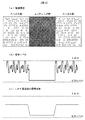
本発明に用いる光情報媒体について説明する。なお、説明を簡単にするため、本発明においては、BDのシステムを前提とする。図1は従来のBCA構造の物理特性、及びその信号波形を示す。(a)は物理構造を示しており、ベース部分であるエンボス部にはデータ領域に準じた変調方法でランダムデータが形成されている。そこに後工程でBCAカッター等を用いて、カッティング部を形成する。このように反射レベルを下げることで、データパターンの“1”を構成し、その他のエンボス部の“0”と反射率の差異で判定が可能となる。(b)は実際に再生した波形を示す。エンボス部はデータパターンで変調されており、高周波成分が検出される。また、カッティング部はデータパターンを焼き切り、反射光量が大きく低下し、ほぼゼロレベル近くまで再生信号強度を下げることができる。(c)は再生用のLPFを通過した後の信号波形を示している。データパターンはユーザデータ領域に準じた高周波成分の信号であり、信号中心レベルとして検出される。その結果、エンボス部はI8H(元波形のトップレベル)よりも下がり、カッティング部はゼロレベル近くで検出されることになる。
[Optical information media]
The optical information medium used in the present invention will be described. In order to simplify the description, the present invention assumes a BD system. FIG. 1 shows physical characteristics of a conventional BCA structure and signal waveforms thereof. (A) shows the physical structure, and random data is formed in the embossed portion, which is the base portion, by a modulation method according to the data area. A cutting part is formed there by using a BCA cutter or the like in a later step. By lowering the reflection level in this way, the data pattern “1” is configured, and determination can be made based on the difference in reflectance from “0” of the other embossed portions. (B) shows the waveform actually reproduced. The embossed portion is modulated with a data pattern, and a high frequency component is detected. In addition, the cutting unit burns out the data pattern, the amount of reflected light is greatly reduced, and the reproduction signal intensity can be lowered to nearly zero level. (C) shows the signal waveform after passing through the LPF for reproduction. The data pattern is a high-frequency component signal according to the user data area, and is detected as a signal center level. As a result, the embossed portion falls below I8H (the top level of the original waveform), and the cutting portion is detected near zero level.
続いて、図2は本発明に用いる光情報媒体のBCA構造の物理特性、及びその信号波形を示す。(a)の物理構造は従来BCAと異なり、データパターン“0”を構成する部分がミラー部、つまりピット等の光回折構造がなく、最も反射光量の高い構造となる。データパターン“1”を構成するエンボス部は、従来BCAのエンボス部と同様の物理構造となる。
(b)の再生波形でその差異が明確となるが、データパターン“1”を構成するエンボス部は従来BCAのデータパターン“0”のエンボス部と同様の反射率となり、従来BCAの信号レベルとは異なる波形となる。データパターン“0”であるミラー部も同様にデータパターンの高周波信号の中心レベルからI8Hへ信号レベルが大きくシフトすることになる。
Next, FIG. 2 shows the physical characteristics of the BCA structure of the optical information medium used in the present invention and its signal waveform. Unlike the conventional BCA, the physical structure of (a) has no mirror part, that is, a light diffractive structure such as a pit in the portion constituting the data pattern “0”, and has the highest reflected light amount. The embossed portion constituting the data pattern “1” has the same physical structure as the embossed portion of the conventional BCA.
Although the difference is clear in the reproduced waveform of (b), the embossed portion constituting the data pattern “1” has the same reflectance as the embossed portion of the conventional BCA data pattern “0”, and the signal level of the conventional BCA Have different waveforms. Similarly, the signal level of the mirror portion having the data pattern “0” is largely shifted from the center level of the high frequency signal of the data pattern to I8H.
そのため、本発明では、BCAに適用するピット成型条件について規定し、従来のBCAと同様に検出できることを目的とする。具体的な方法は、以下に示す通りである。まずピット深さをレーザー波長の略1/4に設計することで、最も反射光量の変化を検出しやすい。なお、このような設計では、プッシュプル信号の検出が困難となるが、BCAの再生においては、トラッキングサーボをかけなくてもよいので、実現が可能である。 Therefore, an object of the present invention is to define the pit molding conditions applied to the BCA and to detect it in the same manner as the conventional BCA. A specific method is as follows. First, by designing the pit depth to be approximately ¼ of the laser wavelength, the change in the amount of reflected light is most easily detected. In such a design, it becomes difficult to detect the push-pull signal. However, since it is not necessary to apply the tracking servo in reproducing the BCA, this can be realized.
次に、ピット形状について評価した結果を示す。特に反射光量の変化つまり信号変調度が最も確保できる条件について検討した。条件はピット長と、ピット幅で比較検討した。 Next, the result of evaluating the pit shape is shown. In particular, the conditions under which the change in the amount of reflected light, that is, the degree of signal modulation can be secured most were examined. The conditions were compared and examined by pit length and pit width.
まず、ピット長はデータ変調の観点から、2T長の連続パターン、8T長の連続パターンで比較する。なお、1Tはチャネルクロックである。 First, the pit length is compared with a continuous pattern of 2T length and a continuous pattern of 8T length from the viewpoint of data modulation. Note that 1T is a channel clock.
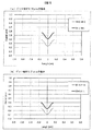
図3は2T長の連続パターンのシミュレーション結果である。(a)はピット幅をトラックピッチの半分である0.16μmとした場合の反射光量を示す。G/Lはそれぞれグルーブつまりオントラック状態と、ランドつまりオフトラック状態の結果を示す。(b)はピット幅を反射光量が極小となるスポットサイズの略半分である0.21μmの結果を示す。信号レベルの1はミラーレベルを基準とし、相対光量比として示す。これらの結果から、2T長の連続パターンの場合、ピット幅が0.21μmとした場合に、より平均反射光量を下げられることがわかる。
FIG. 3 shows a simulation result of a continuous pattern of 2T length. (A) shows the amount of reflected light when the pit width is 0.16 μm, which is half the track pitch. G / L indicates the result of the groove, that is, the on-track state, and the land, that is, the off-track state, respectively. (B) shows the result when the pit width is 0.21 μm, which is approximately half the spot size where the amount of reflected light is minimized. The
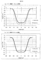
図4は8T長の連続パターンのシミュレーション結果である。(a)、(b)はそれぞれ図3と同様にピット幅を変えた結果である。8T長の連続パターンの場合、ピット中心部分(図中のLength=0)でオントラック、オフトラックによらず、ミラー部基準で、0.25以下となることがわかる。また、ランド部(非ピット部)はミラー部相当の0.9程度となる。この結果から、BCA形成にピットパターンを使用する場合は、ピット部とランド部で信号強度が大きく変わり、BCA再生用のLPFを通過後には、全ての平均化が行われ、限りなく0.5付近に収束することとなる。 FIG. 4 shows a simulation result of a continuous pattern of 8T length. (A), (b) is the result of having changed the pit width similarly to FIG. In the case of a continuous pattern of 8T length, it can be seen that the pit center portion (Length = 0 in the figure) is 0.25 or less on the basis of the mirror portion regardless of on-track or off-track. The land portion (non-pit portion) is about 0.9 corresponding to the mirror portion. From this result, when a pit pattern is used for BCA formation, the signal intensity changes greatly between the pit portion and the land portion, and after passing through the LPF for BCA reproduction, all averaging is performed, and the limit is 0.5. It will converge in the vicinity.
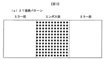
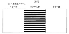
図5〜図7はピット構造のBCAの例を示す。図5は2T連続パターン、図6は8T連続パターン、図7は8T連続パターンを拡張した溝構造パターンである。図3,4の条件から、よりBCAの変調度が確保できるピットパターンとしては、長いピットパターンの中央部が連続的に存在する場合であると言える。つまり、従来のBCAと同様の信号レベルを確保し、且つ後工程を追加しないピット形成型のBCAには、図5、図6のようにランド部があるようなパターンではなく、図7のように長いピットパターン(溝構造)とすることによって、BCA信号変調度が確保できることがわかる。つまり、図4のLength=0の部分のシグナルレベルが検出されることとなる。その結果、ピット幅依存があるが、シグナルレベルでおおよそ0.25以下が実現可能な値となる。なお、BD−ROMの一層ディスク場合、最大反射率が70%と規定されており、また最小変調度(反射光量に対する信号振幅)が40%と規定されているため、存在する最大反射光量はおおよそ56%(70×(100−40/2)/100)となるため、14%(56×0.25)が検出できれば従来と同様の検出方法でも新型のBCAの検出が可能である。なお、BD−ROM二層ディスクの場合は、同様の計算方法から、6%が検出できればよいということになる。 5 to 7 show examples of BCA having a pit structure. 5 shows a 2T continuous pattern, FIG. 6 shows an 8T continuous pattern, and FIG. 7 shows an extended groove structure pattern. From the conditions of FIGS. 3 and 4, it can be said that the pit pattern that can secure the modulation degree of BCA is a case where the central portion of the long pit pattern continuously exists. In other words, the pit formation type BCA that secures the same signal level as the conventional BCA and does not add a post-process is not a pattern having a land portion as shown in FIGS. 5 and 6, but as shown in FIG. It can be seen that the BCA signal modulation degree can be secured by using a long pit pattern (groove structure). That is, the signal level of the portion of Length = 0 in FIG. 4 is detected. As a result, although it depends on the pit width, a signal level of approximately 0.25 or less is a realizable value. In the case of a BD-ROM single-layer disc, the maximum reflectance is defined as 70%, and the minimum modulation degree (signal amplitude with respect to the reflected light amount) is defined as 40%. Since it becomes 56% (70 × (100−40 / 2) / 100), if 14% (56 × 0.25) can be detected, it is possible to detect a new type of BCA using the same detection method as in the prior art. In the case of a BD-ROM double-layer disc, it is sufficient that 6% can be detected from the same calculation method.
なお、本発明の説明においては、簡単のために2T,8Tの連続パターンで比較したが、これに制限されるものではない。例えば、溝構造の実現が困難である場合は、ピット部の長さを確保し、ランド部の長さをできるだけ短くすればよく、例えば、8Tピットと2Tランドの組み合わせのようなパターンにおいてもBCA変調度を比較的容易に確保することが可能である。 In the description of the present invention, for the sake of simplicity, the comparison is made with continuous patterns of 2T and 8T, but the present invention is not limited to this. For example, when it is difficult to realize the groove structure, the length of the pit portion should be ensured and the length of the land portion should be as short as possible. For example, even in a pattern such as a combination of 8T pits and 2T lands, BCA It is possible to ensure the modulation degree relatively easily.
[ディスクの形状]
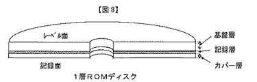
本発明に用いる再生専用ディスクの形状について説明する。図8に1層ROM(再生専用)ディスクを示す。また、図9は2層ROM(再生専用)ディスクを示す。図8に示される1層ROMディスクにはレーベルが書かれる側のレーベル面と、再生するための光ビームが入射する側の記録面が存在する。記録面側から記録面を保護するカバー層、信号が記録されている記録層、そしてその下の基盤層からなる。図9に示される2層ROMディスクにもレーベルが書かれる側のレーベル面と、再生するための光ビームが入射する側の記録面が存在する。記録面側から記録面を保護するカバー層、信号が記録されている記録層(L1)、もう一つの記録層との間を隔てるスペース層、もう一つの信号が記録されている記録層(L0)そしてその下の基盤層からなる。
[Disc shape]
The shape of the read-only disc used in the present invention will be described. FIG. 8 shows a single-layer ROM (reproduction-only) disk. FIG. 9 shows a two-layer ROM (reproduction-only) disk. The single-layer ROM disk shown in FIG. 8 has a label surface on which a label is written and a recording surface on which a light beam for reproduction is incident. It consists of a cover layer that protects the recording surface from the recording surface side, a recording layer on which signals are recorded, and a base layer below it. The two-layer ROM disk shown in FIG. 9 also has a label surface on the side on which the label is written and a recording surface on the side on which the light beam for reproduction is incident. A cover layer that protects the recording surface from the recording surface side, a recording layer (L1) in which signals are recorded, a space layer that separates from another recording layer, and a recording layer (L0) in which another signal is recorded ) And the base layer below it.
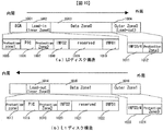
次に1層ROMディスク及び2層ROMディスクの記録層の構造を図10に示す。図10はディスク断面の左側を内周、右側を外周とし模式的にあらわしたものである。図10(a)L0ディスク構造は、1層ROMディスク及び2層ROMディスクの記録層L0のディスク構造を示す。図10(b)L1ディスク構造は、2層ROMディスクの記録層L1のディスク構造を示す。 Next, the structure of the recording layer of the single-layer ROM disk and the double-layer ROM disk is shown in FIG. FIG. 10 schematically shows the disk cross section with the left side being the inner circumference and the right side being the outer circumference. FIG. 10A shows the disk structure of the recording layer L0 of the single-layer ROM disk and the double-layer ROM disk. FIG. 10B shows the disk structure of the recording layer L1 of the two-layer ROM disk.
図10(a)L0ディスク構造において、1001はBCAであり、ディスク固有の情報等が記録されている。1002はInner Zone0であり、ディスクに関する属性の情報や制御情報等が記録されている。Lead-inとも称する。1003はData Zone0であり、AVデータなどのユーザデータが記録されている。1004はOuter Zone0であり制御情報などが記録されている。Inner Zone0(1002)は、Protection Zone1(1005)、PIC(1006)、Protection Zone2(1007)、INFO02(1008)、reseved(1009)、INFO01(1010)からなる。Protection Zone1(1005)はBCA(1001)とPIC(1006)を隔てるための領域である。PIC(1006)はディスクのタイプに関する情報や、ディスクのサイズに関する情報や、ディスクのバージョンに関する情報や、ディスクの構造に関する情報や、チャネルビット長に関する情報や、BCAの有無に関する情報や、適用の最大伝送速度に関する情報などが記録されている。Protection Zone2(1007)は、PIC(1006)とINFO02(1008)を隔てるための領域である。INFO02(1008)には制御情報が記録されている。reseved(1009)は予備の領域である。INFO01(1010)には制御情報が記録されている。Outer Zone0(1004)は、INFO3/4(1011)とProtection Zone3(1012)からなる。INFO3/4(1011)には制御情報が記録されている。Protection Zone3(1012)はINFO3/4(1011)を更に外周部分と隔てる。図10(a)L0ディスク構造の内周から外周に向かっての矢印は、1層ROMディスク及び2層ROMディスクの記録層L0は内周から外周に向かってReadするように記録されていることを示す。
In FIG. 10A, in the L0 disc structure,
図10(b)L1ディスク構造において、1014はInner Zone1であり、ディスクに関する属性の情報や制御情報等が記録されている。Lead-outとも称する。1015はData Zone0であり、AVデータなどのユーザデータが記録されている。1016はOuter Zone1であり制御情報などが記録されている。Inner Zone1(1014)は、Protection Zone1(1017)、PIC(1018)、Protection Zone2(1019)、INFO02(1020)、reseved(1021)、INFO01(1022)からなる。Protection Zone1(1017)はより内周側とPIC(1018)を隔てるための領域である。PIC(1018)はディスクのタイプに関する情報や、ディスクのサイズに関する情報や、ディスクのバージョンに関する情報や、ディスクの構造に関する情報や、チャネルビット長に関する情報や、BCAの有無に関する情報や、適用の最大伝送速度に関する情報などが記録されている。Protection Zone2(1019)は、PIC(1018)とINFO02(1020)を隔てるための領域である。INFO02(1020)には制御情報が記録されている。reseved(1021)は予備の領域である。INFO01(1022)には制御情報が記録されている。Outer Zone1(1016)は、INFO3/4(1023)とProtection Zone3(1024)からなる。INFO3/4(1023)には制御情報が記録されている。Protection Zone3(1024)はINFO3/4(1023)を更に外周部分と隔てる。図10(b)L1ディスク構造の外周から内周に向かっての矢印は、2層ROMディスクの記録層L1は外周から内周に向かってReadするように記録されていることを示す。
In FIG. 10B, in the L1 disc structure,
[データのエンコード処理]
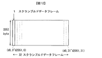
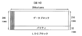
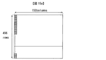
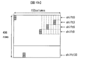
ユーザデータの記録処理について説明する。図11に示すとおり、ユーザデータを2048バイト単位に分割し、それぞれに4バイトの誤り検出コードを付加して2052バイトのデータフレームを構成する。次に、各データフレームに対し図12に示すとおりスクランブル処理を行い、スクランブルドデータフレームを構成する。次に図12に示すとおり、スクランブルドデータフレームを32個集める。次に列順に再配置を行い、図13に示すとおり216行304列のデータブロックを構成する。そして、図14に示すとおり、データブロックの各列に対して(248,216,32)のリードソロモン符号で符号化を行い、32バイトのパリティを付加し新たに248行304列のLDC(Long Distant Code)ブロックを構成する。LDCブロックに対しては次の第1のインターリーブと、第2のインターリーブが処理される。第1のインターリーブは図15aに示されるように、偶数番目の列のデータとそれに続く奇数番目の列のデータを互い違いに挟み込むように再配置を行い496行152列のブロックを構成する。第2のインターリーブは図15b示すとおり、再配置された496行152列のブロックに対し、上から2行単位で、最初の2行はシフトせず、次の2行は左に3バイトシフト、次の2行は6バイトシフト、次の2行は左に9バイトシフトと3バイトずつシフト量を増加させる再配置を行う。第1のインターリーブ、第2のインターリーブを施したデータはLDCクラスタを構成する。
[Data encoding process]
User data recording processing will be described. As shown in FIG. 11, user data is divided into units of 2048 bytes, and an error detection code of 4 bytes is added to each to form a data frame of 2052 bytes. Next, each data frame is scrambled as shown in FIG. 12 to form a scrambled data frame. Next, as shown in FIG. 12, 32 scrambled data frames are collected. Next, rearrangement is performed in the order of columns to form a data block of 216 rows and 304 columns as shown in FIG. Then, as shown in FIG. 14, each column of the data block is encoded with a Reed-Solomon code of (248, 216, 32), and a parity of 32 bytes is added to newly add 248 rows and 304 columns of LDC (Long Distant Code) block. For the LDC block, the next first interleaving and second interleaving are processed. In the first interleave, as shown in FIG. 15a, rearrangement is performed so that even-numbered columns of data and subsequent odd-numbered columns of data are alternately sandwiched to form a block of 496 rows and 152 columns. In the second interleave, as shown in FIG. 15b, for the rearranged block of 496 rows and 152 columns, the first two rows are not shifted in units of two rows from the top, and the next two rows are shifted to the left by 3 bytes. The next two lines are shifted by 6 bytes, and the next two lines are shifted to the left by 9 bytes and rearranged to increase the shift amount by 3 bytes. The data subjected to the first interleave and the second interleave constitute an LDC cluster.
一方、このデータブロックに付加されるアドレスは以下のように生成される。
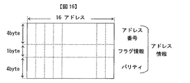
図16に示されるようにデータブロックは16のアドレスユニットに分割され、それぞれに9バイトのアドレス情報が割り当てられる。9バイトの内訳は、4バイトのアドレスと、1バイトのフラグ情報と、5バイトのアドレスとフラグ情報に付加されたパリティとからなる。このアドレスはインターリーブ処理を行ったうえで、6行24列のマトリックスを形成する。同時にユーザー制御データ18バイト、32ユニット分が24行24列のマトリックスに配置される。
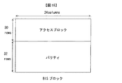
上記の6行24列のマトリックスと24行24列のマトリックスは結合され、図17に示す30行24列のアクセスブロックを形成する。アクセスブロックの各列に対して(62,33,32)のリードソロモン符号で符号化を行い、32バイトのパリティを付加して図18に示す、62行24列のBIS(Burst Indicating Subcode)ブロックを形成する。BISブロックのデータに対し再配置を行い図19に示す496行3列のBISクラスタを構成する。
On the other hand, the address added to this data block is generated as follows.
As shown in FIG. 16, the data block is divided into 16 address units, and 9-byte address information is assigned to each. The breakdown of 9 bytes consists of a 4-byte address, 1-byte flag information, a 5-byte address, and a parity added to the flag information. This address is subjected to an interleaving process to form a 6 × 24 matrix. At the same time, 18 bytes of user control data and 32 units are arranged in a matrix of 24 rows and 24 columns.
The matrix of 6 rows and 24 columns and the matrix of 24 rows and 24 columns are combined to form an access block of 30 rows and 24 columns shown in FIG. Each row of the access block is encoded with a Reed-Solomon code of (62, 33, 32), and a 32-byte parity is added to the BIS (Burst Indicating Subcode) block shown in FIG. Form. The BIS block data is rearranged to form a B96 cluster of 496 rows and 3 columns shown in FIG.
前記のLDCクラスタを38列ずつに分割し、間にBISクラスタのデータを一列ずつ挿入し図20に示すECCクラスタを構成する。 The LDC cluster is divided into 38 columns, and BIS cluster data is inserted between the LDC clusters one by one to form the ECC cluster shown in FIG.
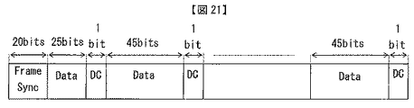
ECCクラスタの各行155バイトのデータに対しては、先頭に20ビットのフレーム同期信号が付加し、155バイトのデータは先頭25ビット、以降は45ビットずつに分割し、間にDCコントロールビットを挿入し、図21に示す記録フレームを構成する。DCコントロールビットは変調後のDSVが0に近くなるように制御される。 A 20-bit frame synchronization signal is added to the head of 155 bytes of data in each row of the ECC cluster, and 155 bytes of data are divided into 25 bits at the beginning and 45 bits thereafter, and a DC control bit is inserted between them. The recording frame shown in FIG. The DC control bit is controlled so that the modulated DSV is close to zero.
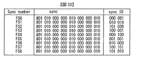
記録フレームのデータに対する変調は図22に示されるテーブルに従って17変調を行う。フレーム同期信号は図23に示されるように30bitsの同期コードを用いて付加される。図23において、#は同期コードの前の変調後のデータが0000もしくは00で終端された場合は1となり、他の場合は0となる。 The modulation of the recording frame data is 17 modulation according to the table shown in FIG. The frame synchronization signal is added using a 30 bits synchronization code as shown in FIG. In FIG. 23, # is 1 when the data after modulation before the synchronization code is terminated with 0000 or 00, and is 0 in other cases.
[BCA]
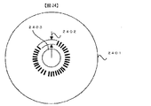
図10で示されたBCAの配置を、光ディスク2401の上から見た配置図で、図24に示す。光ディスク2401の半径21.3mmから22.0mmまでの範囲には、同心円状にバーストカッティングエリア(BCA)2402が形成される。また、2403はセンターホールである。このBCAには、ディスクID等のディスク固有の情報もしくは、ディスクの準拠するフォーマット情報等が格納されている。こうした情報は1周が略4750チャネルビットであるのに対し、4648チャネルビットを占める。
[BCA]
The arrangement of the BCA shown in FIG. 10 is shown in FIG. A burst cutting area (BCA) 2402 is formed concentrically in the radius 21.3 mm to 22.0 mm of the optical disc 2401.
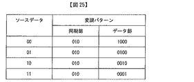
バーストカッティングエリア2402に記録されるデータの変調方法を図25に示す。本変調方式では、2ビットのデータが7ビットデータとして変調される。変調後の7ビットデータは、前半3ビットが同期部、後半4ビットがデータ部として構成される。同期部は“010”のみで構成される。データ部は4ビットのうちのいずれかのビットに“1”が設定され、それ以外のビットは“0”と設定される。図25において、元データが“00”であれば、データ部が“1000”と変調される。同様に元データ“01”、“10”、“11”はそれぞれデータ部“0100”、“0010”、“0001”と変調される。
A modulation method of data recorded in the
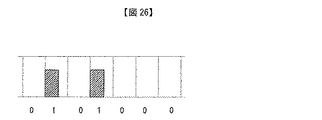
同期部とデータ部がバーストカッティングエリア2402に記録されている状態を模式的に図26に示す。この場合、“0101000”のデータを示している。ビット“1”の場合は、低反射率部が形成される。ビット“0”の場合はこの低反射率部が形成されずに、ディスク反射率の変化がほぼゼロとなる。
FIG. 26 schematically shows a state where the synchronization part and the data part are recorded in the
バーストカッティングエリア2402に記録されるデータ構造を図27に示す。図27において、各行が5バイトで構成される。各行の先頭1バイトは同期バイトであり、後方4バイトがデータとされる。
The data structure recorded in the
第1行目はプリアンブルとされ、全て00hとされる。
第1の同期バイトは第1行目のみに用いるため、これを検出することにより、BCAコードの開始位置を検出することが可能である。もしくは、第1の同期バイト以降の00hデータと併せて検出することも可能である。第2行目から第33行目までは、4行単位で領域が区分される。第2行目から第5行目までには、ユーザデータI0,0からI0,15の16バイトのデータが配置される。続いて、第6行目から第9行目までには、第2行目から第5行目までのユーザデータI0,0からI0,15に対応する16バイトのパリティC0,0からC0,15が配置される。この第2行目から第5行目までのユーザデータと第6行目から第9行目までのパリティによって、1つのECCブロックが構成される。
The first line is a preamble, and is all 00h.
Since the first synchronization byte is used only for the first line, it is possible to detect the start position of the BCA code by detecting this. Alternatively, it can be detected together with 00h data after the first synchronization byte. From the second line to the 33rd line, the area is divided in units of four lines. From the second line to the fifth line, 16-byte data of user data I0,0 to I0,15 is arranged. Subsequently, from the sixth line to the ninth line, a 16-byte parity C0,0 to C0,15 corresponding to the user data I0,0 to I0,15 from the second line to the fifth line is shown. Is placed. One ECC block is configured by the user data from the second row to the fifth row and the parity from the sixth row to the ninth row.
同様に、第10行目から第13行目までにユーザデータI1,0からI1,15が配置され、第14行目から第17行目に対応するパリティC1,0からC1,15が配置される。第18行目から第21行目までにユーザデータI2,0からI2,15が配置され、第22行目から第25行目に対応するパリティC2,0からC2,15が配置される。第26行目から第29行目までにユーザデータI3,0からI3,15が配置され、第30行目から第33行目に対応するパリティC3,0からC3,15が配置される。 Similarly, user data I1,0 to I1,15 are arranged from the 10th line to the 13th line, and parities C1,0 to C1,15 corresponding to the 14th line to the 17th line are arranged. The User data I2,0 to I2,15 are arranged from the 18th line to the 21st line, and parities C2,0 to C2,15 corresponding to the 22nd line to the 25th line are arranged. User data I3,0 to I3,15 are arranged from the 26th line to the 29th line, and parities C3,0 to C3,15 corresponding to the 30th line to the 33rd line are arranged.
第2行目から第5行目の同期バイトはSB00とされる。第6行目から第9行目までの同期バイトはSB01とされる。第10行目から第13行目までの同期バイトはSB02とされる。第14行目から第17行目までの同期バイトはSB03とされる。第18行目から第21行目までの同期バイトはSB10とされる。第22行目から第25行目までの同期バイトはSB11とされる。第26行目から第29行目までの同期バイトはSB12とされる。第30行目から第33行目までの同期バイトはSB13とされる。第34行目にはデータは配置されず、同期バイトのSB32のみが配置される。図27のデータは図25の変調方式に従い、変調される前のデータを示している。そのデータ量は166バイトとなる。(=5バイト×4行×8セット+5バイト+1バイト)この情報が変調された結果、4648チャネルビットとなる。(=166×8×7/2)
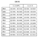
図27の同期信号の具体的なデータ列を図28に示す。なお、図28の例は変調後のチャネルビット列として表される。28チャネルビットの同期バイトは14チャネルビットのシンクボディと、14チャネルビットのシンクIDとで構成される。14チャネルビットのシンクボディは7チャネルビットのシンクボディ1と、7チャネルビットのシンクボディ2とで構成される。14チャネルビットのシンクIDは、7チャネルビットのシンクID1と、7チャネルビットのシンクID2とで構成される。
なお、シンクボディは先に記した本来の変調則に従わないパターンとなっている。すなわち、図25に記されるように本変調則に従えば、その同期部は“010”とされるはずである。しかし、シンクボディ2の同期部は“010”とは異なる“001”とされている。従って、同期バイトをデータから識別することが可能である。
The synchronization byte in the second to fifth lines is SB00. The synchronization byte from the sixth line to the ninth line is SB01. The synchronization byte from the 10th line to the 13th line is SB02. The synchronization byte from the 14th line to the 17th line is SB03. The synchronization byte from the 18th line to the 21st line is SB10. The synchronization byte from the 22nd line to the 25th line is SB11. The synchronization byte from the 26th line to the 29th line is SB12. The synchronization byte from the 30th line to the 33rd line is SB13. In the 34th row, no data is arranged and only the SB32 of the synchronization byte is arranged. The data in FIG. 27 shows data before being modulated in accordance with the modulation scheme in FIG. The amount of data is 166 bytes. (= 5 bytes × 4 rows × 8 sets + 5 bytes + 1 byte) This information is modulated to result in 4648 channel bits. (= 166 × 8 × 7/2)
A specific data string of the synchronization signal in FIG. 27 is shown in FIG. Note that the example of FIG. 28 is expressed as a modulated channel bit string. The 28-channel bit synchronization byte is composed of a 14-channel bit sync body and a 14-channel bit sync ID. The 14-channel bit sync body includes a 7-channel
The sync body has a pattern that does not follow the original modulation rule described above. That is, as shown in FIG. 25, according to the present modulation rule, the synchronization unit should be “010”. However, the synchronization part of the
各同期バイトのシンクボディ1はいずれも“010 0001”とされ、シンクボディ2は“001 0100”とされる。これに対し、シンクIDは、同期バイト毎に異なる値とされ、これにより同期バイトを識別することが可能となっている。このように、各同期バイトが異なるため、識別が可能となる。
The
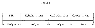
BCAコードのECCブロックの構成を図29に示す。ECCはRS(248,216,33)のリードソロモン符号が用いられる。これは、図14のECCブロックと同様のリードソロモン符号である。ただし、BCAコードのECCブロックは図29のように、先頭の200バイトは固定データとされ、例えばFFhが使用される。この固定データに続く16バイトのデータが実質的なBCAのユーザデータとされる。200バイトの固定データと、16バイトのBCAデータとを用いて、36バイトのパリティが計算する。 The structure of the ECC block of the BCA code is shown in FIG. As the ECC, a Reed-Solomon code of RS (248, 216, 33) is used. This is a Reed-Solomon code similar to the ECC block of FIG. However, in the ECC block of the BCA code, as shown in FIG. 29, the first 200 bytes are fixed data, and for example, FFh is used. The 16-byte data following the fixed data is regarded as substantial BCA user data. A parity of 36 bytes is calculated using 200 bytes of fixed data and 16 bytes of BCA data.
なお、本発明における216バイトのデータのうち、先頭200バイトは固定データであり、光ディスクには記録されない。同様に、32バイトのパリティのうち、先頭16バイトのパリティC0からC15のみが光ディスク1に記録され、残りの16バイトのパリティは記録されない。復号時には、200バイトの固定データは、同一の値がそのまま用いられる。また、記録されない16バイトのパリティは消失フラグとして復号される。つまり、32バイトのパリティのうち、後半の16バイトは位置するパリティが、消失したものとして処理される。パリティの1/2が消失したとしても、その位置が既知であるため、元のパリティを復号することが可能である。
Of the 216-byte data according to the present invention, the first 200 bytes are fixed data and are not recorded on the optical disk. Similarly, of the 32-byte parity, only the first 16-byte parities C0 to C15 are recorded on the
このように、ユーザデータエリアに記録されるユーザデータのECCと同じRS(248,216,33)を用いることで、BCAにおいても非常に強力なエラー訂正能力を実現可能となる。また、同一のハードウェアでの構成が可能となるので、回路規模を低減でき、コスト低減することができる。更に、32バイトのみを記録すればよく、248バイト全てを記録する場合に比べ、データ容量を大きくすることができる。 Thus, by using the same RS (248, 216, 33) as the ECC of user data recorded in the user data area, it is possible to realize a very strong error correction capability even in BCA. In addition, since the configuration with the same hardware is possible, the circuit scale can be reduced and the cost can be reduced. Furthermore, only 32 bytes need be recorded, and the data capacity can be increased as compared with the case where all 248 bytes are recorded.
次に、BCAのデータブロックの構成を図30に示す。本発明において、4個のECCブロックがバーストカッティングエリア2402に記録される。各ECCブロックの16バイトのデータは、先頭の1バイトのコンテンツコードと、続く15バイトのコンテンツデータで構成される。BCAのコンテンツコードは、先頭のビット7からビット2までの6ビットがアプリケーションIDとされ、最後のビット1、ビット0の2ビットがシーケンス番号とされる。
Next, FIG. 30 shows the configuration of the BCA data block. In the present invention, four ECC blocks are recorded in the
光ディスク記録再生装置は、取り決められたアプリケーションIDを有する光ディスクに対してのみ、データの記録する、もしくは再生することが可能とされる。例えば、特定のアプリケーションIDを有するディスクに対して、コンテンツデータを保護するために必要な、コンテンツの暗号化/復号化の鍵情報等を記録することができる。 The optical disc recording / reproducing apparatus can record or reproduce data only to an optical disc having the decided application ID. For example, content encryption / decryption key information required for protecting content data can be recorded on a disc having a specific application ID.
シーケンス番号は2ビットで構成され、“00”、“01”、“10”、“11”のいずれかとされる。各ECCブロックのコンテンツデータが14バイト以下である場合にはそれぞれのシーケンス番号は“00”とされる。 The sequence number is composed of 2 bits and is “00”, “01”, “10”, or “11”. When the content data of each ECC block is 14 bytes or less, each sequence number is set to “00”.
次にコンテンツデータの格納方法を示す。例えば、4つのECCブロックのうち、先頭の2個のECCブロックの各コンテンツデータとして、同一のコンテンツデータを格納した場合(この場合は、同一アプリケーションIDの同一コンテンツデータの2重書きである)、それぞれのECCブロックのシーケンス番号は“00”とされる。すなわち、同一のコンテンツデータを記録する場合には、2つのECCブロックのシーケンス番号は同一番号とされる。 Next, a content data storage method will be described. For example, when the same content data is stored as the content data of the first two ECC blocks among the four ECC blocks (in this case, the same content data with the same application ID is written twice). The sequence number of each ECC block is “00”. That is, when the same content data is recorded, the sequence numbers of the two ECC blocks are the same number.
続いて、残りの2個のECCブロックに、最初のECCブロックのアプリケーションIDとは異なるコンテンツデータを24バイト格納する場合、1番目のシーケンス番号は“00”とされ、2番目のECCブロックのシーケンス番号は“01”とされる。すなわち、複数のECCブロックにまたがる場合には、通し番号が格納される。 Subsequently, when 24 bytes of content data different from the application ID of the first ECC block are stored in the remaining two ECC blocks, the first sequence number is set to “00” and the sequence of the second ECC block. The number is “01”. In other words, when a plurality of ECC blocks are spanned, serial numbers are stored.
このように、各ECCブロックに、アプリケーションIDとシーケンス番号が記録されるので、それらから判断して、いずれのECCブロックに所望のデータが格納されているのか、また多重書きであるかという識別が可能である。 As described above, since the application ID and the sequence number are recorded in each ECC block, it is possible to identify which ECC block stores the desired data and whether or not the multiple writing is performed. Is possible.
なお、図30のデータブロックのBCAコンテンツコード、及びコンテンツデータが、図27の先頭ECCブロックのI0,0からI0,15に対応する。 Note that the BCA content code and content data of the data block of FIG. 30 correspond to I0,0 to I0,15 of the first ECC block of FIG.
[ディスクの記録再生装置]
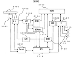
本発明に好適として形状、データのエンコード処理、BCAについて説明した光ディスクの再生を行う記録再生装置の説明を図31を用いて行う。図31は記録再生装置のブロック図である。図31において、3100は図8,9,10に示される再生専用ディスクもしくは、概ね共通の形状をとる記録可能ディスクである。3101はディスク3100を回転させるディスクモータ、3102はディスク3100にレーザー光を照射し、反射光を検出し再生信号を得る光ピックアップである。また3102は記録時には的確に整形された波形のレーザー光をディスク3100に照射して記録を行う。3103はアナログフロントエンドであり、光ピックアップ3102で検出された信号の波形整形やサーボ信号の生成などを行う。3104は復調処理回路であり、波形整形された信号の2値化や、データのエンコード処理で説明した1−7変調に基づいた復調処理などを行う。3105はDRAM(Dynamic Randum Access Memory)であり、復調処理されたデータ、訂正処理中、入出力データ、変調処理前のデータなどの一時記憶に用いられる。3106はECC(Error Correction Circuit)であり、再生処理時にはDRAM3105に一時記憶された復調処理済のデータに対し、誤り訂正処理をおこない、記録処理時には、DRAM3105に一時記憶された入力データに対し、誤り訂正符号の付加を行う。3107はインターフェース回路であり、DRAM105に一時記憶されたデータを出力端子3114からの出力したり、入力端子3113からの入力データをDRAM3105に記憶させたり、DRAM3105に記憶されたBCA関連情報の出力端子3115からの出力などインターフェース処理を行う。3113と3115共通化することもできる。また、双方向化することで3113,3114,3115を共通化することも可能である。3108は変調回路であり、記録時には、DRAM3105から読み出したデータに対して、データのエンコード処理で説明した1−7変調に基づいた変調処理を行い、変調データをLDD(Laser Diode Driver)3109に供給する。LDD3109は記録時には、変調データに対して、記録に適切な記録波形を光ピックアップ3102に供給し、ピックアップ3102は記録波形に従って発光して記録を行う。3110はBCAデコーダーであり、BCAの再生時には、[BCA]で説明されたように低反射率の有無によって記録された、BCAのデータブロックのデコード処理を行う。
[Disc recording / playback device]
A recording / reproducing apparatus that performs reproduction of an optical disc described for the shape, data encoding process, and BCA is described with reference to FIG. FIG. 31 is a block diagram of the recording / reproducing apparatus. In FIG. 31,
3100…ディスク、3101…ディスクモータ、3102…光ピックアップ 3100: Disc, 3101: Disc motor, 3102 ... Optical pickup
Claims (10)
Priority Applications (3)
| Application Number | Priority Date | Filing Date | Title |
|---|---|---|---|
| JP2011053707A JP2012190509A (en) | 2011-03-11 | 2011-03-11 | Optical information medium, optical information recording and reproducing device and optical information recording and reproducing method |
| US13/412,649 US20120230172A1 (en) | 2011-03-11 | 2012-03-06 | Optical information medium, optical information recording/reproducing apparatus, and optical information recording/reproducing method |
| CN2012100620965A CN102682806A (en) | 2011-03-11 | 2012-03-09 | Optical information medium, optical information recording/reproducing apparatus, and optical information recording/reproducing method |
Applications Claiming Priority (1)
| Application Number | Priority Date | Filing Date | Title |
|---|---|---|---|
| JP2011053707A JP2012190509A (en) | 2011-03-11 | 2011-03-11 | Optical information medium, optical information recording and reproducing device and optical information recording and reproducing method |
Publications (2)
| Publication Number | Publication Date |
|---|---|
| JP2012190509A true JP2012190509A (en) | 2012-10-04 |
| JP2012190509A5 JP2012190509A5 (en) | 2014-04-17 |
Family
ID=46795502
Family Applications (1)
| Application Number | Title | Priority Date | Filing Date |
|---|---|---|---|
| JP2011053707A Pending JP2012190509A (en) | 2011-03-11 | 2011-03-11 | Optical information medium, optical information recording and reproducing device and optical information recording and reproducing method |
Country Status (3)
| Country | Link |
|---|---|
| US (1) | US20120230172A1 (en) |
| JP (1) | JP2012190509A (en) |
| CN (1) | CN102682806A (en) |
Citations (5)
| Publication number | Priority date | Publication date | Assignee | Title |
|---|---|---|---|---|
| JPH03116540A (en) * | 1989-09-29 | 1991-05-17 | Toshiba Corp | Disk device |
| JP2003030856A (en) * | 2001-07-17 | 2003-01-31 | Pioneer Electronic Corp | Optical disk and recording/reproducing device |
| JP2005116126A (en) * | 2003-10-10 | 2005-04-28 | Fuji Photo Film Co Ltd | Optical information recording medium |
| US20060274617A1 (en) * | 2005-06-03 | 2006-12-07 | Musto James J | Techniques for forming burst cutting area mark |
| JP2010135005A (en) * | 2008-12-04 | 2010-06-17 | Sony Corp | Optical recording medium and method for manufacturing the same |
Family Cites Families (4)
| Publication number | Priority date | Publication date | Assignee | Title |
|---|---|---|---|---|
| KR20040069750A (en) * | 2003-01-30 | 2004-08-06 | 삼성전자주식회사 | Optical information storage medium |
| JP2005285153A (en) * | 2004-03-26 | 2005-10-13 | Toshiba Corp | Information recording medium, information reproducing apparatus, information reproducing method, and information recording method |
| TW200634801A (en) * | 2004-11-17 | 2006-10-01 | Hitachi Maxell | Optical information-recording medium |
| JP4348744B2 (en) * | 2006-05-10 | 2009-10-21 | 日本電気株式会社 | Optical information recording medium and method for producing optical information recording medium |
-
2011
- 2011-03-11 JP JP2011053707A patent/JP2012190509A/en active Pending
-
2012
- 2012-03-06 US US13/412,649 patent/US20120230172A1/en not_active Abandoned
- 2012-03-09 CN CN2012100620965A patent/CN102682806A/en active Pending
Patent Citations (5)
| Publication number | Priority date | Publication date | Assignee | Title |
|---|---|---|---|---|
| JPH03116540A (en) * | 1989-09-29 | 1991-05-17 | Toshiba Corp | Disk device |
| JP2003030856A (en) * | 2001-07-17 | 2003-01-31 | Pioneer Electronic Corp | Optical disk and recording/reproducing device |
| JP2005116126A (en) * | 2003-10-10 | 2005-04-28 | Fuji Photo Film Co Ltd | Optical information recording medium |
| US20060274617A1 (en) * | 2005-06-03 | 2006-12-07 | Musto James J | Techniques for forming burst cutting area mark |
| JP2010135005A (en) * | 2008-12-04 | 2010-06-17 | Sony Corp | Optical recording medium and method for manufacturing the same |
Also Published As
| Publication number | Publication date |
|---|---|
| US20120230172A1 (en) | 2012-09-13 |
| CN102682806A (en) | 2012-09-19 |
Similar Documents
| Publication | Publication Date | Title |
|---|---|---|
| CN101601092B (en) | Optical disk, optical disk device, optical disk recording/reproducing method, and integrated circuit | |
| US20120017137A1 (en) | Disc recording medium, disk drive apparatus, reproduction method, and disk manufacturing method | |
| JP4690306B2 (en) | Recording medium having intermittent or alternating wobble pits, and apparatus and method for forming, recording and reproducing data on the recording medium | |
| JP4734453B2 (en) | Information recording medium and method for reproducing information recording medium | |
| US20040076101A1 (en) | High-density read-only optical disc, method for recording disc information (DI) on the high-density read-only optica disc, and method for reproducing data recorded on the high-density read-only optical disc | |
| US7913146B2 (en) | Optical disk manufacturing method and device, optical disk, and reproduction method thereof | |
| JP5789661B2 (en) | Optical disc, recording method, reproduction method | |
| JP2005536002A (en) | High-density optical disk, address or / and servo information recording method for high-density optical disk, and method for reproducing data recorded on high-density optical disk | |
| JP2012190509A (en) | Optical information medium, optical information recording and reproducing device and optical information recording and reproducing method | |
| JP2012069226A (en) | Optical information medium, optical information recording/reproduction device and optical information recording/reproduction method | |
| JP2013004155A (en) | Optical information medium, optical information recording and playback device and optical information recording and playback method | |
| KR100596306B1 (en) | Linking area data recording and reproducing method of high-density reproducing optical disc, and therefore high-density reproducing optical disc | |
| JP2014032712A (en) | Recording method and reproduction method for optical disk and optical disk for recording | |
| JP2005536003A (en) | Address recording method for high-density read-only disc, high-density read-only disc including addresses recorded by the method, and method for reproducing high-density read-only disc | |
| JP4905423B2 (en) | Disc recording medium, disc drive apparatus, and playback method | |
| KR100576165B1 (en) | Linking area data recording and reproducing method of high-density reproducing optical disc, and therefore high-density reproducing optical disc | |
| JP4993013B2 (en) | Disc recording medium, recording method, recording apparatus, reproducing method, and reproducing apparatus | |
| KR100513333B1 (en) | Method for recording and reproducing data on linking area of high density read only optical disc and high density read only optical disc therof | |
| JP2013004162A (en) | Optical disk, recorder of optical disk and playback device of optical disk | |
| KR20040023386A (en) | Method for recording address information of high density read only optical disc and high density read only optical disc therof | |
| JP2012069209A (en) | Optical information recording/reproducing method and recording/reproducing device, and control device of copy | |
| KR20080113474A (en) | Recordable recording medium and data recording method using the same | |
| JP2008071486A (en) | Information recording medium, information recording apparatus and method, information reproducing apparatus and method, and computer program | |
| JP2011181180A (en) | Recording method and reproducing method | |
| JP2008226449A (en) | Digital signal reproduction method |
Legal Events
| Date | Code | Title | Description |
|---|---|---|---|
| A521 | Request for written amendment filed |
Free format text: JAPANESE INTERMEDIATE CODE: A523 Effective date: 20140205 |
|
| A621 | Written request for application examination |
Free format text: JAPANESE INTERMEDIATE CODE: A621 Effective date: 20140205 |
|
| A521 | Request for written amendment filed |
Free format text: JAPANESE INTERMEDIATE CODE: A523 Effective date: 20140205 |
|
| A977 | Report on retrieval |
Free format text: JAPANESE INTERMEDIATE CODE: A971007 Effective date: 20150212 |
|
| A131 | Notification of reasons for refusal |
Free format text: JAPANESE INTERMEDIATE CODE: A131 Effective date: 20150217 |
|
| A02 | Decision of refusal |
Free format text: JAPANESE INTERMEDIATE CODE: A02 Effective date: 20150623 |