JP2012190704A - Direct-current circuit breaker - Google Patents
Direct-current circuit breaker Download PDFInfo
- Publication number
- JP2012190704A JP2012190704A JP2011054336A JP2011054336A JP2012190704A JP 2012190704 A JP2012190704 A JP 2012190704A JP 2011054336 A JP2011054336 A JP 2011054336A JP 2011054336 A JP2011054336 A JP 2011054336A JP 2012190704 A JP2012190704 A JP 2012190704A
- Authority
- JP
- Japan
- Prior art keywords
- circuit breaker
- connection conductor
- sub
- main
- connection
- Prior art date
- Legal status (The legal status is an assumption and is not a legal conclusion. Google has not performed a legal analysis and makes no representation as to the accuracy of the status listed.)
- Granted
Links
Images




Landscapes
- Driving Mechanisms And Operating Circuits Of Arc-Extinguishing High-Tension Switches (AREA)
Abstract
Description
本発明の実施形態は、直流遮断器に関する。 Embodiments described herein relate generally to a DC circuit breaker.
一般に、電気鉄道用き電回路のような直流回路に、直流遮断器が設けられている。直流遮断器は、直列に接続された主遮断器及び副遮断器を有している。副遮断器は直流回路の直流電源の電源側に設けられ、主遮断器は直流回路の負荷側に設けられている。直流遮断器は、事故電流や通電電流などを遮断するものである。 Generally, a DC circuit breaker is provided in a DC circuit such as an electric railway feeder circuit. The DC circuit breaker has a main circuit breaker and a sub circuit breaker connected in series. The sub circuit breaker is provided on the power source side of the DC power source of the DC circuit, and the main circuit breaker is provided on the load side of the DC circuit. The DC circuit breaker interrupts accident currents and energized currents.
主遮断器には、事故電流遮断時に系統に蓄えられたエネルギを吸収するエネルギ吸収素子と転流回路とが並列に接続されている。転流回路は、直列に接続された転流コンデンサ、転流リアクトル及び転流スイッチを有している。 The main circuit breaker is connected in parallel with an energy absorption element that absorbs energy stored in the system when the fault current is interrupted and a commutation circuit. The commutation circuit includes a commutation capacitor, a commutation reactor, and a commutation switch connected in series.
直流回路に流れる電流を遮断する場合は、主遮断器を開極(OFF)し、転流スイッチを閉じて(ONして)転流コンデンサが放電し、主遮断器に流れる電流(直流回路に流れる電流)と逆方向の転流電流を通電する。これにより、主遮断器に流れる電流を0にして遮断することができる。主遮断器に流れる電流が0となると、主遮断器に並列に接続されたエネルギ吸収素子を電流が流れるため、電流は減衰される。
一方、副遮断器は、転流スイッチを閉じた後に開極(OFF)し、電源側から負荷側に流れる電流が減衰し0となると、遮断が完了する。
When interrupting the current flowing through the DC circuit, the main circuit breaker is opened (OFF), the commutation switch is closed (ON), the commutation capacitor is discharged, and the current flowing through the main circuit breaker (in the DC circuit) A commutation current in the opposite direction to the flowing current). Thereby, the electric current which flows into a main circuit breaker can be made into 0, and can be interrupted | blocked. When the current flowing through the main circuit breaker becomes zero, the current flows through the energy absorbing elements connected in parallel to the main circuit breaker, and thus the current is attenuated.
On the other hand, the secondary circuit breaker is opened (OFF) after closing the commutation switch, and when the current flowing from the power source side to the load side is attenuated to zero, the circuit breaker is completed.
主遮断器は、主真空バルブと、主真空バルブの中に密封された開閉電極とを含んだ主遮断部を有している。副遮断器は、副真空バルブと、副真空バルブの中に密封された開閉電極とを含んだ副遮断部を有している。主真空バルブ及び副真空バルブは、隣合って設けられている。 The main circuit breaker has a main circuit breaker including a main vacuum valve and an open / close electrode sealed in the main vacuum valve. The sub circuit breaker has a sub circuit breaker including a sub vacuum valve and an open / close electrode sealed in the sub vacuum valve. The main vacuum valve and the sub vacuum valve are provided next to each other.
主遮断器は、事故電流遮断の場合は高速開極機構により、また、負荷電流遮断や無負荷開極の際は主遮断器通常操作機構により、開極される(OFF)。副遮断器は、副遮断器通常操作機構により、開極(OFF)/閉極(ON)される。 The main circuit breaker is opened (OFF) by a high-speed opening mechanism in the case of an accidental current interruption, and by a main circuit breaker normal operation mechanism in the case of load current interruption or no-load opening. The secondary circuit breaker is opened (OFF) / closed (ON) by the secondary circuit breaker normal operation mechanism.
ところで、上記直流遮断器において、事故が発生した際の遮断電流は、隣合う主真空バルブ及び副真空バルブの中の開閉電極に真空アーク放電を生起させることになる。このため、主真空バルブの中の開閉電極での真空アーク放電と、副真空バルブの中の開閉電極での真空アーク放電と、の両方から、大きな電磁力が発生することになる。 By the way, in the DC circuit breaker, the interruption current when an accident occurs causes a vacuum arc discharge to be generated in the open / close electrodes in the adjacent main vacuum valve and sub vacuum valve. For this reason, a large electromagnetic force is generated from both the vacuum arc discharge at the open / close electrode in the main vacuum valve and the vacuum arc discharge at the open / close electrode in the sub vacuum valve.
これにより、主遮断器、副遮断器、これらを支える構造物等は、上記の電磁力に耐えられる機械的強度を有する必要がある。
さらに、主真空バルブの中の開閉電極での真空アーク放電から発生する電磁力が副真空バルブの中の開閉電極での真空アーク放電に働き、また、副真空バルブの中の開閉電極での真空アーク放電から発生する電磁力が主真空バルブの中の開閉電極での真空アーク放電に働くことになる。必要な遮断性能を得るため、主遮断器及び副遮断器の開閉電極のサイズを大きくする必要がある。
Thereby, the main circuit breaker, the sub circuit breaker, the structure supporting these, etc. need to have mechanical strength that can withstand the electromagnetic force.
Furthermore, the electromagnetic force generated from the vacuum arc discharge at the open / close electrode in the main vacuum valve acts on the vacuum arc discharge at the open / close electrode in the sub vacuum valve, and the vacuum at the open / close electrode in the sub vacuum valve. The electromagnetic force generated from the arc discharge acts on the vacuum arc discharge at the open / close electrode in the main vacuum valve. In order to obtain the required breaking performance, it is necessary to increase the size of the switching electrodes of the main breaker and the sub breaker.
この発明は以上の点に鑑みなされたもので、その目的は、主遮断器及び副遮断器間に作用する電磁力を低減することができ、主遮断部及び副遮断部のサイズの大型化を抑制することができる直流遮断器を提供することにある。 The present invention has been made in view of the above points, and an object thereof is to reduce the electromagnetic force acting between the main circuit breaker and the sub circuit breaker, and to increase the size of the main circuit breaker and the sub circuit breaker. It is providing the DC circuit breaker which can be suppressed.
一実施形態に係る直流遮断器は、
軸方向に沿った真空アーク放電を遮断可能な主遮断部を有した主遮断器と、
前記軸方向に沿った真空アーク放電を遮断可能な副遮断部を有し、前記主遮断器に直列に接続された副遮断器と、
前記主遮断器に並列に接続された転流回路と、
前記主遮断器に並列に接続されたエネルギ吸収素子と、を備え、
前記主遮断部と、前記副遮断部とは、前記軸方向にずれて位置していることを特徴としている。
The DC circuit breaker according to an embodiment is
A main circuit breaker having a main circuit breaker capable of interrupting vacuum arc discharge along the axial direction;
A secondary circuit breaker having a secondary circuit breaker capable of blocking vacuum arc discharge along the axial direction, and connected in series to the main circuit breaker;
A commutation circuit connected in parallel to the main circuit breaker;
An energy absorbing element connected in parallel to the main circuit breaker,
The main blocking part and the sub blocking part are characterized by being shifted in the axial direction.
以下、図面を参照しながら一実施形態に係る直流遮断器について詳細に説明する。この実施形態において、直流遮断器が、直流回路としての電気鉄道用き電回路に設けられている場合について説明する。 Hereinafter, a DC circuit breaker according to an embodiment will be described in detail with reference to the drawings. In this embodiment, the case where the DC circuit breaker is provided in an electric railway feeder circuit as a DC circuit will be described.
図1に示すように、電気鉄道用き電回路は、直流遮断器20を備えている他、直流電源である電源21、及び負荷22を備えている。直流遮断器20は、電源21及び負荷22とともに直列に接続されている。この実施形態において、負荷22は、車両本体、パンタグラフ及び車輪等を有した電気車両である。直流遮断器20は、架線23等を介して負荷22のパンタグラフに電気的に接続されている。電源21は、レール24等を介してレール24に接した負荷22の車輪に電気的に接続されている。
As shown in FIG. 1, the electric railway feeding circuit includes a
図2に示すように、直流遮断器20は、主遮断器12と、副遮断器13と、エネルギ吸収素子14と、転流回路15と、高速開極機構3と、主遮断器12用の通常操作機構4と、副遮断器13用の通常操作機構5と、を備えている。
As shown in FIG. 2, the
主遮断器12及び副遮断器13は、直列に接続されている。また、主遮断器12は負荷22側に接続され、副遮断器13は電源21側に接続されている。エネルギ吸収素子14は、主遮断器12に並列に接続されている。この実施形態において、エネルギ吸収素子14は、抵抗で形成されている。転流回路15は、転流スイッチ16、転流コンデンサ17及び転流リアクトル18を有している。転流スイッチ16、転流コンデンサ17及び転流リアクトル18は、直列に接続されている。転流コンデンサ17は、図示しない充電装置により、所定の電圧に充電されている。
The
次に、この実施形態に係る実施例1乃至実施例の直流遮断器20について説明する。
(実施例1)
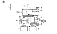
図2及び図3に示すように、主遮断器12は、主真空バルブ1と、主真空バルブ1の中に密封された固定電極及び可動電極とを有している。固定電極及び可動電極は、これらが対向した軸方向に沿って生起される真空アーク放電を遮断可能な主遮断部を形成している。この実施形態において、軸方向は第1方向Zである。
Next, the
Example 1
As shown in FIGS. 2 and 3, the
副遮断器13は、副真空バルブ2と、副真空バルブ2の中に密封された固定電極及び可動電極とを有している。固定電極及び可動電極は、これらが対向した軸方向(第1方向Z)に沿って生起される真空アーク放電を遮断可能な副遮断部を形成している。
The
主遮断器12において、固定電極には第1接続導体31が接続され、可動電極には第2接続導体32が接続されている。副遮断器13において、固定電極には第3接続導体33が接続され、可動電極には第4接続導体34が接続されている。第4接続導体34は、可動電極に接続された第1導体34aと、第1導体34aに接続された第2導体34bとを含んでいる。
In the
第1乃至第4接続導体31乃至34は、剛性の高いものである。この実施形態において、第1接続導体31、第3接続導体33及び第2導体34bは銅板で形成され、第2接続導体32及び第1導体34aは、銅製のシャフトで形成されている。
第1接続導体31には第1コネクタ6が接続され、第4接続導体34(第2導体34b)には第2コネクタ7が接続されている。
The first to
The
この実施形態において、第1中継導体8及び第2中継導体9は、主遮断器12に、エネルギ吸収素子14及び転流回路15の両方を並列に接続するためのものである。第1中継導体8は第1接続導体31に接続され、第2中継導体9は第3接続導体33に接続されている。
In this embodiment, the
なお、第1中継導体8及び第2中継導体9は、主遮断器12に、エネルギ吸収素子14及び転流回路15の一方を並列に接続するためのものであってもよい。この場合、エネルギ吸収素子14及び転流回路15の他方は、別の中継導体を用いて主遮断器12に並列に接続されていてもよい。
The
高速開極機構3及び通常操作機構4は、第2接続導体32を可動させることにより、主遮断器12の可動電極を開極(OFF)位置及び閉極(ON)位置に切替え可能である。通常操作機構5は、第4接続導体34(第1導体34a)を可動させることにより、副遮断器13の可動電極を開極(OFF)位置及び閉極(ON)位置に切替え可能である。
The high-
主遮断器12の主遮断部と、副遮断器13の副遮断部とは、軸方向(第1方向Z)に添って互いにずれて位置している。この実施形態において、主遮断器12の主遮断部と、副遮断器13の副遮断部とは、軸方向(第1方向Z)に直交した方向に延在した第3接続導体33を挟んで上下に位置しているため、軸方向(第1方向Z)に完全にずれて位置しているということができる。
なお、直流遮断器20による、事故が発生した際の遮断電流10の遮断方法については後述する。
The
In addition, the interruption | blocking method of the interruption | blocking current 10 at the time of the accident by the
(実施例2)
図2及び図3に示すように、主遮断器12の可動電極は、スライドコンタクト又はフレキシブルコンタクトを介して第2接続導体32に接続されている。同様に、副遮断器13の可動電極も、スライドコンタクト又はフレキシブルコンタクトを介して第4接続導体34(第1導体34a)に接続されている。
上記した他、実施例2の直流遮断器20は、上記実施例1の直流遮断器20と同様に形成されている。
(Example 2)
As shown in FIGS. 2 and 3, the movable electrode of the
In addition to the above, the
(実施例3)
図2及び図4に示すように、第1中継導体8及び第2中継導体9は、第1接続導体31及び第2接続導体32の間に位置し、互いに平行に延在している。エネルギ吸収素子14に電流11が流れる際、第1中継導体8に流れる電流11の向きと、第2中継導体9に流れる電流11の向きとは、反平行となる。
上記した他、実施例3の直流遮断器20は、上記実施例2の直流遮断器20と同様に形成されている。
(Example 3)
As shown in FIGS. 2 and 4, the
In addition to the above, the
(実施例4)
図2及び図5に示すように、第1コネクタ6は、軸方向(第1方向Z)に直交した接続方向に接続可能である。同様に、第2コネクタ7も接続方向に接続可能である。この実施形態において、接続方向は第2方向Yである。
Example 4
As shown in FIGS. 2 and 5, the
第1接続導体31、第3接続導体33、第2導体34b、第1中継導体8及び第2中継導体9は、接続方向(第2方向Y)に平行に延在している。なお、第1中継導体8及び第2中継導体9のそれぞれのコネクタも、接続方向に接続可能である。
The
主遮断器12(主真空バルブ1)及び副遮断器13(副真空バルブ2)は、接続方向(第2方向Y)及び軸方向(第1方向Z)に直交した方向(第3方向X)にずれて位置している。
上記した他、実施例4の直流遮断器20は、上記実施例3の直流遮断器20と同様に形成されている。
The main circuit breaker 12 (main vacuum valve 1) and the sub circuit breaker 13 (sub vacuum valve 2) are in a direction (third direction X) orthogonal to the connection direction (second direction Y) and the axial direction (first direction Z). It is located in the position.
In addition to the above, the
(実施例5)
図2及び図6に示すように、主遮断器12(主真空バルブ1)及び副遮断器13(副真空バルブ2)は、接続方向(第2方向Y)にずれて位置している。
上記した他、実施例5の直流遮断器20は、上記実施例4の直流遮断器20と同様に形成されている。
(Example 5)
As shown in FIGS. 2 and 6, the main circuit breaker 12 (main vacuum valve 1) and the sub circuit breaker 13 (sub vacuum valve 2) are shifted in the connection direction (second direction Y).
In addition to the above, the
(実施例6)
図2及び図7に示すように、主遮断器12(主真空バルブ1)及び副遮断器13(副真空バルブ2)は、軸方向(第1方向Z)に直交した方向において、第3方向X及び接続方向(第2方向Y)から傾斜した方向にずれて位置している。
(Example 6)
2 and 7, the main circuit breaker 12 (main vacuum valve 1) and the sub circuit breaker 13 (sub vacuum valve 2) are arranged in the third direction in the direction orthogonal to the axial direction (first direction Z). The position is shifted in the direction inclined from X and the connection direction (second direction Y).
上記した他、実施例6の直流遮断器20は、上記実施例4の直流遮断器20と同様に形成されている。
In addition to the above, the
次に、事故の発生により電気鉄道用き電回路に事故電流が発生した際に、この実施形態の直流遮断器20を用いることにより、主遮断器12及び副遮断器13に流れる遮断電流10を遮断する方法について説明する。
図1、図2、図3、図及び図8に示すように、電気鉄道用き電回路に過大な事故電流が流れた場合、タイミングt1において、図示しない制御部から高速開極機構3に制御信号が与えられることにより、高速開極機構3は主遮断器12の可動電極を開極位置に切替えることができる。
Next, when an accident current occurs in the electric railway feeder circuit due to the occurrence of an accident, by using the
As shown in FIG. 1, FIG. 2, FIG. 3, FIG. 8 and FIG. 8, when an excessive fault current flows in the electric railway power circuit, control is performed from a control unit (not shown) to the high-
その後、タイミングt2において、上記制御部から転流スイッチ16に制御信号が与えられ、転流スイッチ16はONに切替えられる。転流コンデンサ17は、放電を開始し、主遮断器12に流れる電流(電気鉄道用き電回路に流れる電流)と逆方向の転流電流を通電する。これにより、その後のタイミングt3において、主遮断器12に流れる第1電流(遮断電流)を0にして遮断することができる。主遮断器12に流れる第1電流が0となると、主遮断器12に並列に接続されたエネルギ吸収素子14を電流11が流れるため、電流は減衰されることとなる。
Thereafter, at timing t2, a control signal is given from the control unit to the
一方、転流スイッチ16がONに切替えられた後、上記制御部から通常操作機構5に制御信号が与えられることにより、通常操作機構5は副遮断器13の可動電極を開極位置に切替えることができる。エネルギ吸収素子14の作用により、副遮断器13に流れる第2電流(遮断電流)は減衰するため、タイミングt4において、副遮断器13に流れる第2電流を0にして遮断することができる。
上記のように、主遮断器12及び副遮断器13に流れる遮断電流10の遮断が完了する。
On the other hand, after the
As described above, the interruption of the interruption current 10 flowing through the
以上のように構成された一実施形態に係る直流遮断器20によれば、直流遮断器20は、主遮断器12と、副遮断器13と、エネルギ吸収素子14と、転流回路15とを備えている。主遮断器12は、軸方向に沿った真空アーク放電を遮断可能な主遮断部を有している。副遮断器13は、軸方向に沿った真空アーク放電を遮断可能な副遮断部を有し、主遮断器12に直列に接続されている。エネルギ吸収素子14及び転流回路15は、主遮断器12に並列に接続されている。
According to the
(1)実施例1乃至実施例6において、主遮断器12の主遮断部と、副遮断器13の副遮断部とは、軸方向(第1方向Z)に添って互いにずれて位置している。主遮断器12の主遮断部と、副遮断器13の副遮断部とは隣合って位置していないため、事故が発生した際に主遮断器12から副遮断器13に与える電磁力の影響を低減することができ、逆もまた同様に、副遮断器13から主遮断器12に与える電磁力の影響を低減することができる。
(1) In the first to sixth embodiments, the main circuit breaker of the
これにより、主遮断器12や副遮断器13等が破壊されたり、振動してしまったりすることを低減することができ、直流遮断器20の安定した動作を確保することができる。しかも、直流遮断器20の大幅な改造無しに、必要な機械的強度を低減することができる。
Thereby, it can reduce that the
さらに、主遮断器12からの電磁力が副遮断器13での真空アーク放電に働くこと、及び副遮断器13からの電磁力が主遮断器12での真空アーク放電に働くこと、を低減することができる。このため、主遮断器12及び副遮断器13の固定電極及び可動電極のサイズの大型化を抑制することができる。
Further, the electromagnetic force from the
(2)実施例2乃至実施例6において、主遮断器12の可動電極は、スライドコンタクト又はフレキシブルコンタクトを介して第2接続導体32に接続されている。このため、
開極/閉極時等に、主遮断器12から副遮断器13に、及び副遮断器13から主遮断器12に、振動を伝わりにくくすることができる。そのため、必要な機械的強度を、一層、低減することができる。
(2) In Example 2 to Example 6, the movable electrode of the
It is possible to make it difficult to transmit vibration from the
(3)実施例3乃至実施例6において、第1中継導体8に流れる電流11の向きと、第2中継導体9に流れる電流11の向きとを、反平行とすることができる。第1中継導体8に流れる電流11が生起する電磁力と、第2中継導体9に流れる電流11が生起する電磁力とは、互いに相殺されるため、副遮断器13に働く電磁力を一層低減することができる。
(3) In the third to sixth embodiments, the direction of the current 11 flowing through the
(4)実施例4では接続方向(第2方向Y)の、実施例5では第3方向Xの、サイズを縮小することができるため、直流遮断器20の小型化を図ることができる。
(4) Since the size of the connection direction (second direction Y) in the fourth embodiment and the third direction X in the fifth embodiment can be reduced, the
上記のことから、主遮断器12及び副遮断器13間に作用する電磁力を低減することができ、主遮断部及び副遮断部のサイズの大型化を抑制することができる直流遮断器20を得ることができる。
From the above, the
なお、この発明は上記実施の形態そのままに限定されるものではなく、実施段階ではその要旨を逸脱しない範囲で構成要素を変形して具体化可能である。また、上記実施の形態に開示されている複数の構成要素の適宜な組み合わせにより、種々の発明を形成できる。例えば、実施形態に示される全構成要素から幾つかの構成要素を削除してもよい。さらに、異なる実施例にわたる構成要素を適宜組み合わせてもよい。 Note that the present invention is not limited to the above-described embodiment as it is, and can be embodied by modifying the components without departing from the scope of the invention in the implementation stage. Various inventions can be formed by appropriately combining a plurality of constituent elements disclosed in the embodiments. For example, some components may be deleted from all the components shown in the embodiment. Furthermore, constituent elements over different embodiments may be appropriately combined.
例えば、主遮断器12及び副遮断器13は、軸方向に沿って位置していてもよい。
主遮断器12及び副遮断器13間の接続のため、第2接続導体32に第3接続導体33が接続されているが、これに限定されるものではなく、種々変形可能であり、例えば、第4接続導体34に第1接続導体31が接続されていてもよい。
For example, the
For the connection between the
上記直流遮断器は、上記電気鉄道用き電回路に限らず、各種の直流回路に適用可能である。
本発明は、上記直流遮断器に限らず、各種の直流遮断器に適用可能である。
The DC circuit breaker is not limited to the electric railway feeder circuit but can be applied to various DC circuits.
The present invention is not limited to the DC circuit breaker, but can be applied to various DC circuit breakers.
1…主真空バルブ、2…副真空バルブ、3…高速開極機構、4…通常操作機構、5…通常操作機構、6…第1コネクタ、7…第2コネクタ、8…第1中継導体、9…第2中継導体、10…遮断電流、11…電流、12…主遮断器、13…副遮断器、14…エネルギ吸収素子、15…転流回路、16…転流スイッチ、17…転流コンデンサ、18…転流リアクトル、20…直流遮断器、31…第1接続導体、32…第2接続導体、33…第3接続導体、34…第4接続導体、34a…第1導体、34b…第2導体、Z…第1方向、Y…第2方向、X…第3方向。
DESCRIPTION OF
Claims (6)
前記軸方向に沿った真空アーク放電を遮断可能な副遮断部を有し、前記主遮断器に直列に接続された副遮断器と、
前記主遮断器に並列に接続された転流回路と、
前記主遮断器に並列に接続されたエネルギ吸収素子と、を備え、
前記主遮断部と、前記副遮断部とは、前記軸方向にずれて位置していることを特徴とする直流遮断器。 A main circuit breaker having a main circuit breaker capable of interrupting vacuum arc discharge along the axial direction;
A secondary circuit breaker having a secondary circuit breaker capable of blocking vacuum arc discharge along the axial direction, and connected in series to the main circuit breaker;
A commutation circuit connected in parallel to the main circuit breaker;
An energy absorbing element connected in parallel to the main circuit breaker,
The DC circuit breaker characterized in that the main circuit breaker and the sub circuit breaker are offset from each other in the axial direction.
前記主遮断部を形成する可動電極に接続された第2接続導体と、
前記副遮断部を形成する固定電極に接続された第3接続導体と、
前記副遮断部を形成する可動電極に接続された第4接続導体と、をさらに備え、
前記第2接続導体に前記第3接続導体が接続され、又は前記第4接続導体に前記第1接続導体が接続されていることを特徴とする請求項1に記載の直流遮断器。 A first connection conductor connected to a fixed electrode forming the main blocking portion;
A second connecting conductor connected to the movable electrode forming the main blocking portion;
A third connection conductor connected to the fixed electrode forming the sub-blocking portion;
A fourth connection conductor connected to the movable electrode forming the sub-blocking portion, and
The DC circuit breaker according to claim 1, wherein the third connection conductor is connected to the second connection conductor, or the first connection conductor is connected to the fourth connection conductor.
前記主遮断部を形成する可動電極に接続された第2接続導体と、
前記主遮断器に、前記転流回路を並列に接続するための、前記エネルギ吸収素子を並列に接続するための、又は前記転流回路及びエネルギ吸収素子の両方を並列に接続するための第1中継導体及び第2中継導体と、をさらに備え、
前記第1中継導体及び第2中継導体は、前記第1接続導体及び第2接続導体の間に位置し、互いに平行に延在していることを特徴とする請求項1に記載の直流遮断器。 A first connection conductor connected to a fixed electrode forming the main blocking portion;
A second connecting conductor connected to the movable electrode forming the main blocking portion;
A first circuit breaker for connecting the commutation circuit in parallel to the main circuit breaker, for connecting the energy absorption element in parallel, or for connecting both the commutation circuit and the energy absorption element in parallel. A relay conductor and a second relay conductor,
2. The DC circuit breaker according to claim 1, wherein the first relay conductor and the second relay conductor are located between the first connection conductor and the second connection conductor and extend in parallel with each other. .
前記主遮断部を形成する可動電極に接続された第2接続導体と、
前記副遮断部を形成する固定電極に接続された第3接続導体と、
前記副遮断部を形成する可動電極に接続された第4接続導体と、
前記第1接続導体又は第2接続導体に接続され、接続方向に接続可能な第1コネクタと、
前記第3接続導体又は第4接続導体に接続され、前記接続方向に接続可能な第2コネクタと、をさらに備え、
前記主遮断器及び副遮断器は、前記接続方向及び軸方向に直交した方向にずれて位置していることを特徴とする請求項1に記載の直流遮断器。 A first connection conductor connected to a fixed electrode forming the main blocking portion;
A second connecting conductor connected to the movable electrode forming the main blocking portion;
A third connection conductor connected to the fixed electrode forming the sub-blocking portion;
A fourth connection conductor connected to the movable electrode forming the sub-blocking portion;
A first connector connected to the first connection conductor or the second connection conductor and connectable in a connection direction;
A second connector connected to the third connection conductor or the fourth connection conductor and connectable in the connection direction;
2. The DC circuit breaker according to claim 1, wherein the main circuit breaker and the sub circuit breaker are shifted from each other in a direction orthogonal to the connection direction and the axial direction.
前記主遮断部を形成する可動電極に接続された第2接続導体と、
前記副遮断部を形成する固定電極に接続された第3接続導体と、
前記副遮断部を形成する可動電極に接続された第4接続導体と、
前記第1接続導体又は第2接続導体に接続され、接続方向に接続可能な第1コネクタと、
前記第3接続導体又は第4接続導体に接続され、前記接続方向に接続可能な第2コネクタと、をさらに備え、
前記主遮断器及び副遮断器は、前記接続方向にずれて位置していることを特徴とする請求項1に記載の直流遮断器。 A first connection conductor connected to a fixed electrode forming the main blocking portion;
A second connecting conductor connected to the movable electrode forming the main blocking portion;
A third connection conductor connected to the fixed electrode forming the sub-blocking portion;
A fourth connection conductor connected to the movable electrode forming the sub-blocking portion;
A first connector connected to the first connection conductor or the second connection conductor and connectable in a connection direction;
A second connector connected to the third connection conductor or the fourth connection conductor and connectable in the connection direction;
The DC circuit breaker according to claim 1, wherein the main circuit breaker and the sub circuit breaker are shifted from each other in the connection direction.
前記主遮断部を形成する可動電極に接続された第2接続導体と、
前記副遮断部を形成する固定電極に接続された第3接続導体と、
前記副遮断部を形成する可動電極に接続された第4接続導体と、
前記第1接続導体又は第2接続導体に接続され、接続方向に接続可能な第1コネクタと、
前記第3接続導体又は第4接続導体に接続され、前記接続方向に接続可能な第2コネクタと、をさらに備え、
前記主遮断器及び副遮断器は、前記軸方向に直交した方向において、前記接続方向及び軸方向に直交した方向並びに前記接続方向、から傾斜した方向にずれて位置していることを特徴とする請求項1に記載の直流遮断器。 A first connection conductor connected to a fixed electrode forming the main blocking portion;
A second connecting conductor connected to the movable electrode forming the main blocking portion;
A third connection conductor connected to the fixed electrode forming the sub-blocking portion;
A fourth connection conductor connected to the movable electrode forming the sub-blocking portion;
A first connector connected to the first connection conductor or the second connection conductor and connectable in a connection direction;
A second connector connected to the third connection conductor or the fourth connection conductor and connectable in the connection direction;
The main circuit breaker and the sub circuit breaker are located in a direction perpendicular to the axial direction and shifted from the connection direction, the direction orthogonal to the axial direction, and the direction inclined from the connection direction. The DC circuit breaker according to claim 1.
Priority Applications (1)
| Application Number | Priority Date | Filing Date | Title |
|---|---|---|---|
| JP2011054336A JP5677145B2 (en) | 2011-03-11 | 2011-03-11 | DC circuit breaker |
Applications Claiming Priority (1)
| Application Number | Priority Date | Filing Date | Title |
|---|---|---|---|
| JP2011054336A JP5677145B2 (en) | 2011-03-11 | 2011-03-11 | DC circuit breaker |
Publications (2)
| Publication Number | Publication Date |
|---|---|
| JP2012190704A true JP2012190704A (en) | 2012-10-04 |
| JP5677145B2 JP5677145B2 (en) | 2015-02-25 |
Family
ID=47083645
Family Applications (1)
| Application Number | Title | Priority Date | Filing Date |
|---|---|---|---|
| JP2011054336A Expired - Fee Related JP5677145B2 (en) | 2011-03-11 | 2011-03-11 | DC circuit breaker |
Country Status (1)
| Country | Link |
|---|---|
| JP (1) | JP5677145B2 (en) |
Cited By (1)
| Publication number | Priority date | Publication date | Assignee | Title |
|---|---|---|---|---|
| WO2020121525A1 (en) * | 2018-12-14 | 2020-06-18 | 東芝エネルギーシステムズ株式会社 | Direct-current circuit breaker |
Citations (2)
| Publication number | Priority date | Publication date | Assignee | Title |
|---|---|---|---|---|
| JPS5173266A (en) * | 1974-12-23 | 1976-06-24 | Hitachi Ltd | SHINKU SHADANKI |
| JP2010287460A (en) * | 2009-06-12 | 2010-12-24 | Hitachi Ltd | Commutation type DC circuit breaker |
-
2011
- 2011-03-11 JP JP2011054336A patent/JP5677145B2/en not_active Expired - Fee Related
Patent Citations (2)
| Publication number | Priority date | Publication date | Assignee | Title |
|---|---|---|---|---|
| JPS5173266A (en) * | 1974-12-23 | 1976-06-24 | Hitachi Ltd | SHINKU SHADANKI |
| JP2010287460A (en) * | 2009-06-12 | 2010-12-24 | Hitachi Ltd | Commutation type DC circuit breaker |
Cited By (3)
| Publication number | Priority date | Publication date | Assignee | Title |
|---|---|---|---|---|
| WO2020121525A1 (en) * | 2018-12-14 | 2020-06-18 | 東芝エネルギーシステムズ株式会社 | Direct-current circuit breaker |
| JPWO2020121525A1 (en) * | 2018-12-14 | 2021-09-27 | 東芝エネルギーシステムズ株式会社 | DC circuit breaker |
| JP7150876B2 (en) | 2018-12-14 | 2022-10-11 | 東芝エネルギーシステムズ株式会社 | DC circuit breaker |
Also Published As
| Publication number | Publication date |
|---|---|
| JP5677145B2 (en) | 2015-02-25 |
Similar Documents
| Publication | Publication Date | Title |
|---|---|---|
| US20150022928A1 (en) | Hybrid dc circuit breaking device | |
| KR101521545B1 (en) | Device and method to interrupt high voltage direct current | |
| CN101888939B (en) | Method and apparatus for limiting the switch-on current and for discharging the DC voltage intermediate circuit | |
| CN106716583B (en) | DC disconnector | |
| EP0532045B1 (en) | Electrical power supply system | |
| EP3242308B1 (en) | Electromagnetic repulsion actuator for circuit breaker | |
| US12506332B2 (en) | DC solid-state circuit breaker with a solid-state aided airgap that provides a fail-safe mechanism | |
| JP7465997B2 (en) | Solid Isolation Switch | |
| US20140226247A1 (en) | Dc voltage line circuit breaker | |
| JPH11297170A (en) | Dc arc-extinguishing method and device | |
| KR20140102257A (en) | Electric vehicle drive system | |
| CN107533926B (en) | Bypass switch, method of providing a conductive path, and power system | |
| KR20140095184A (en) | Device and method to interrupt direct current | |
| JP2006032077A (en) | DC circuit breaker | |
| KR101689180B1 (en) | Vacuum interrupter and operating method thereof | |
| JP5677145B2 (en) | DC circuit breaker | |
| JP2010238391A (en) | DC circuit breaker | |
| US10529522B2 (en) | Circuit breaker | |
| JP5074325B2 (en) | DC power supply | |
| JP2014044904A (en) | Dc interrupting device | |
| JP2015226435A (en) | DC breaker | |
| KR20180072335A (en) | Device and method for interrupting dc current by injection of reverse current using vacuum gap switch | |
| JP7279155B2 (en) | DC current interrupter | |
| US20250357743A1 (en) | Switching apparatus for dc electric grids | |
| Feng et al. | Improving Fault Current Interruption Capability of Contactors in EV Battery Packs with SiC MOSFET Commutation Circuit |
Legal Events
| Date | Code | Title | Description |
|---|---|---|---|
| RD04 | Notification of resignation of power of attorney |
Free format text: JAPANESE INTERMEDIATE CODE: A7424 Effective date: 20131205 |
|
| RD04 | Notification of resignation of power of attorney |
Free format text: JAPANESE INTERMEDIATE CODE: A7424 Effective date: 20131212 |
|
| RD04 | Notification of resignation of power of attorney |
Free format text: JAPANESE INTERMEDIATE CODE: A7424 Effective date: 20131219 |
|
| RD04 | Notification of resignation of power of attorney |
Free format text: JAPANESE INTERMEDIATE CODE: A7424 Effective date: 20131226 |
|
| RD04 | Notification of resignation of power of attorney |
Free format text: JAPANESE INTERMEDIATE CODE: A7424 Effective date: 20140109 |
|
| A621 | Written request for application examination |
Free format text: JAPANESE INTERMEDIATE CODE: A621 Effective date: 20140122 |
|
| A977 | Report on retrieval |
Free format text: JAPANESE INTERMEDIATE CODE: A971007 Effective date: 20140918 |
|
| A131 | Notification of reasons for refusal |
Free format text: JAPANESE INTERMEDIATE CODE: A131 Effective date: 20140924 |
|
| A521 | Written amendment |
Free format text: JAPANESE INTERMEDIATE CODE: A523 Effective date: 20141112 |
|
| TRDD | Decision of grant or rejection written | ||
| A01 | Written decision to grant a patent or to grant a registration (utility model) |
Free format text: JAPANESE INTERMEDIATE CODE: A01 Effective date: 20141202 |
|
| A61 | First payment of annual fees (during grant procedure) |
Free format text: JAPANESE INTERMEDIATE CODE: A61 Effective date: 20141226 |
|
| R151 | Written notification of patent or utility model registration |
Ref document number: 5677145 Country of ref document: JP Free format text: JAPANESE INTERMEDIATE CODE: R151 |
|
| LAPS | Cancellation because of no payment of annual fees |