JP2012190830A - Solder melting device - Google Patents

Solder melting device Download PDF

Info

Publication number
JP2012190830A
JP2012190830A JP2011050456A JP2011050456A JP2012190830A JP 2012190830 A JP2012190830 A JP 2012190830A JP 2011050456 A JP2011050456 A JP 2011050456A JP 2011050456 A JP2011050456 A JP 2011050456A JP 2012190830 A JP2012190830 A JP 2012190830A
Authority
JP
Japan
Prior art keywords
substrate
presser
heating body
solder
heating
Prior art date
Legal status (The legal status is an assumption and is not a legal conclusion. Google has not performed a legal analysis and makes no representation as to the accuracy of the status listed.)
Pending
Application number
JP2011050456A
Other languages
Japanese (ja)
Inventor
Hiroyuki Masaki
宏之 柾木
Current Assignee (The listed assignees may be inaccurate. Google has not performed a legal analysis and makes no representation or warranty as to the accuracy of the list.)
Hakko Corp
Hakko Co Ltd
Original Assignee
Hakko Corp
Hakko Co Ltd
Priority date (The priority date is an assumption and is not a legal conclusion. Google has not performed a legal analysis and makes no representation as to the accuracy of the date listed.)
Filing date
Publication date
Application filed by Hakko Corp, Hakko Co Ltd filed Critical Hakko Corp
Priority to JP2011050456A priority Critical patent/JP2012190830A/en
Publication of JP2012190830A publication Critical patent/JP2012190830A/en
Pending legal-status Critical Current

Links

Images

Landscapes

  • Electric Connection Of Electric Components To Printed Circuits (AREA)

Abstract

PROBLEM TO BE SOLVED: To provide a solder melting device capable of melting only a part of solder on a substrate.SOLUTION: A solder melting device 10 is equipped with: a heating body 16 which supports a lower side of a predetermined part on which a part of solder on a substrate is positioned, and has a heating upper surface; a base 12 which has an upper surface positioned below an upper surface 16c of the heating body 16; and a retaining mechanism 18 for retaining the substrate placed on the upper surface 16c of the heating body 16 against the heating body 16. The substrate larger than the upper surface 16c is placed on the upper surface 16c of the heating body 16 to heat the substrate locally. The retaining mechanism 18 has a retaining portion 35c which is retained on the substrate, and the retaining portion 35c retains the substrate from an upper side at a position deviated to a side part from the upper surface 16c of the heating body 16, so as to make the substrate stick to the upper surface 16c of the heating body 16.

Description

本発明は、はんだ溶融装置に関するものである。   The present invention relates to a solder melting apparatus.

従来、下記特許文献1及び2に開示されているように、基板上のはんだを溶融させるためのはんだ溶融装置が知られている。特許文献1に開示されたはんだ溶融装置は、電子部品が実装された基板を載置可能なホットプレートを備えており、このホットプレートによって基板の全体を加熱する。これにより、ソルダーペーストを溶融させて、電子部品を基板にはんだ付けする。一方、特許文献2に開示されたはんだ溶融装置では、不活性ガス室内に配置されたホットプレートと、はんだ付けする基板がこのホットプレートに載置される下位置と、それよりも上方で、不活性ガス室外に位置する上位置との間で基板を昇降させる昇降機構と、が設けられている。この装置に設けられたホットプレートは、基板よりも大きな形状であり、載置された基板の全体を加熱する。このはんだ溶融装置では、リフロー加熱用電力及び不活性ガス消費量を低減することができるとともに、装置を小型化することができる。   Conventionally, as disclosed in Patent Documents 1 and 2 below, a solder melting apparatus for melting solder on a substrate is known. The solder melting apparatus disclosed in Patent Document 1 includes a hot plate on which a substrate on which electronic components are mounted can be placed, and the entire substrate is heated by this hot plate. As a result, the solder paste is melted and the electronic component is soldered to the substrate. On the other hand, in the solder melting apparatus disclosed in Patent Document 2, a hot plate disposed in an inert gas chamber, a lower position where a substrate to be soldered is placed on the hot plate, and a position above the hot plate are ineffective. And an elevating mechanism for elevating the substrate between the upper position located outside the active gas chamber. The hot plate provided in this apparatus has a larger shape than the substrate, and heats the entire mounted substrate. In this solder melting apparatus, the power for reflow heating and the amount of inert gas consumed can be reduced, and the apparatus can be miniaturized.

特開平6−232544号公報JP-A-6-232544 特許第3529633号公報Japanese Patent No. 3529633

特許文献1及び2に開示されたはんだ溶融装置は、ホットプレートによって基板の全体を加熱する構成であるため、基板上に実装される全ての電子部品を同時にはんだ付けする場合に使用される。一方、基板上に実装された電子部品のうち一部の不良の電子部品のみを取り外し修理する場合のように、一部の電子部品を固定するはんだのみを溶融させる場合には、前記特許文献1及び2に開示されたはんだ溶融装置を用いることはできない。例えば、LED基板のLED部品等はんだ付け面が部品の底面にある場合には、一部の不良部品のみを取り替えることはできないため、基板全体を破棄していた。   Since the solder melting apparatus disclosed in Patent Documents 1 and 2 is configured to heat the entire board by a hot plate, it is used when all electronic components mounted on the board are soldered simultaneously. On the other hand, when only the solder that fixes some electronic components is melted, such as when only some defective electronic components mounted on the board are removed and repaired, the above-mentioned Patent Document 1 is used. And the solder melting apparatus disclosed in 2 cannot be used. For example, when the soldering surface of the LED component such as the LED component on the LED substrate is on the bottom surface of the component, only a part of the defective component cannot be replaced.

そこで、本発明は、前記従来技術を鑑みてなされたものであり、その目的とするところは、基板上の一部のはんだのみを溶融できるはんだ溶融装置を提供することにある。   Therefore, the present invention has been made in view of the above prior art, and an object thereof is to provide a solder melting apparatus capable of melting only a part of solder on a substrate.

前記の目的を達成するため、本発明は、基板を局所的に加熱して、前記基板上の一部のはんだを溶融させるためのはんだ溶融装置であって、前記一部のはんだが位置する所定部位の基板の下側を支え、加熱することが可能な上面を有する加熱体と、前記加熱体の前記上面よりも下方に位置する上面を有する基台と、を備え、前記加熱体の前記上面には、当該上面よりも大きな前記基板が載置され、前記基板を局所的に加熱するはんだ溶融装置である。   In order to achieve the above object, the present invention provides a solder melting apparatus for locally heating a substrate to melt a part of the solder on the substrate, wherein the part of the solder is located. A heating body having an upper surface capable of supporting and heating the lower side of the substrate of the part, and a base having an upper surface positioned below the upper surface of the heating body, and the upper surface of the heating body Is a solder melting apparatus on which the substrate larger than the upper surface is placed and locally heats the substrate.

本発明では、加熱体の上面に基板が載置されると、この基板は基台の上面に対して浮いた状態となり、基板と基台の上面との間には間隙ができる。このとき、加熱体の上面は、載置される基板の大きさに比べると小さくなっているため、基板は加熱体によって基板の下側より局所的に支えられ加熱されることになる。したがって、基板上の一部のはんだのみを溶融させることができる。このため、基板に実装された電子部品のうち一部の電子部品を取り外すような場合でも、このはんだ溶融装置を使用することができる。   In the present invention, when the substrate is placed on the upper surface of the heating body, the substrate floats with respect to the upper surface of the base, and a gap is formed between the substrate and the upper surface of the base. At this time, since the upper surface of the heating body is smaller than the size of the substrate to be placed, the substrate is locally supported from the lower side of the substrate by the heating body and heated. Therefore, only a part of the solder on the substrate can be melted. For this reason, this solder melting apparatus can be used even when part of the electronic components mounted on the board is removed.

ここで、前記はんだ溶融装置は、前記加熱体の前記上面に載せられた前記基板を前記加熱体に対して押さえ付けるための押え機構を備えており、前記押え機構は、前記基板に押さえ付けられる押え部を有し、この押え部によって前記基板が前記加熱体の前記上面に密着するように、前記押え部によって前記基板を上から押さえ付けるのが好ましい。   Here, the solder melting apparatus includes a pressing mechanism for pressing the substrate placed on the upper surface of the heating body against the heating body, and the pressing mechanism is pressed against the substrate. It is preferable to have a pressing part and press the substrate from above by the pressing part so that the pressing part closely contacts the upper surface of the heating body.

この態様では、溶融させたいはんだが位置する基板の所定部位の下側が加熱体の上面に接触するように、基板が加熱体の上面上に載置され、加熱体上面により支えられる。そして、基板は押え部によって上から押さえ付けられ加熱体の上面に密着する。このため、基板が傾くことなく加熱体の上面に密着するように基板を押さえる。したがって、加熱体の熱を効果的に基板の所望部位に伝えることができる。なお、押え部は、加熱体の上面位置から側方に位置ずれしたところを上から押さえるのが好ましい。   In this aspect, the substrate is placed on the upper surface of the heating body and supported by the upper surface of the heating body so that the lower side of the predetermined portion of the substrate where the solder to be melted is located is in contact with the upper surface of the heating body. And a board | substrate is pressed down from the top by the pressing part, and closely_contact | adheres to the upper surface of a heating body. For this reason, a board | substrate is pressed down so that it may contact | adhere to the upper surface of a heating body, without tilting. Therefore, the heat of the heating body can be effectively transmitted to a desired portion of the substrate. In addition, it is preferable that the press part presses from the upper side the position displaced laterally from the upper surface position of the heating element.

前記押え機構は、前記基板を上から押さえる押え位置と、この押え位置から前記押え部を退避させる退避位置との間で、前記押え部を移動可能に構成されているのが好ましい。   It is preferable that the presser mechanism is configured to be able to move the presser part between a presser position where the substrate is pressed from above and a retreat position where the presser part is retracted from the presser position.

この態様では、押え部を押え位置に位置させて加熱体によって基板を加熱することにより、基板上において加熱体の上方に位置するはんだを溶融させることができる。そして、はんだ溶融後、押え部を退避側方向に移動させることにより、基板と加熱体の密着を緩めることにより、基板上の部品の熱を速やかに下げることができる。また、押え部を退避位置に移動させることにより、基板を加熱体上にセットするとき、又は基板を加熱体から取り外すときに押え部が邪魔にならないようにすることができる。   In this aspect, the solder positioned above the heating body on the substrate can be melted by positioning the presser portion at the pressing position and heating the substrate by the heating body. Then, after the solder is melted, the heat of the components on the board can be quickly reduced by moving the presser part in the retracting direction to loosen the adhesion between the board and the heating element. Further, by moving the presser part to the retracted position, the presser part can be prevented from getting in the way when the substrate is set on the heating body or when the substrate is removed from the heating body.

前記押え機構は、前記押え部を移動させるための操作部と、前記操作部が操作されるとそれに応じて前記押え部を移動させる連動機構と、を備えていてもよい。この態様では、操作部が操作されることにより、押え部が移動する。すなわち、操作部を操作すると、退避位置にあった押え部を押え位置まで移動させることができ、また操作部を操作すると、押え位置にあった押え部を退避位置まで移動させることができる。このため、基板を加熱部上にセットする作業、および基板を取り外す作業を楽に行うことができる。   The presser mechanism may include an operation unit for moving the presser unit, and an interlocking mechanism for moving the presser unit in response to the operation unit being operated. In this aspect, the presser portion is moved by operating the operation portion. That is, when the operation unit is operated, the presser part that is at the retracted position can be moved to the presser position, and when the operation part is operated, the presser part that is at the presser position can be moved to the retracted position. For this reason, the operation | work which sets a board | substrate on a heating part and the operation | work which removes a board | substrate can be performed easily.

また、加熱終了後、操作部を操作し、前記押え部を退避側方向に移動させることにより、加熱体の上面に対する基板の押さえ付けを解除することができる。このことにより基板上の温度を速やかに下げることができる。つまり、押え機構による押え付けを解除しない場合には温度の低下に時間のかかるものになるので、押え機構による押さえ付けを解除することにより、本加熱後の熱を速やかに下げ、部品への熱影響を少なくすることができる。   Further, after the heating is completed, the operation unit is operated, and the pressing unit is moved in the retracting direction, so that pressing of the substrate against the upper surface of the heating body can be released. As a result, the temperature on the substrate can be quickly lowered. In other words, if the presser mechanism is not released, it will take a long time to lower the temperature.By releasing the presser mechanism, the heat after the main heating is quickly reduced, and the heat to the parts is reduced. The influence can be reduced.

前記押え部は、弾性的に変形する材質で構成されるとともに、前記基板に押さえ付けられたときに弾性的に変形して前記基板を押圧するのが好ましい。この態様では、押え部が基板を加熱体に押さえ付ける際に弾性的に変形し、この弾性力によって基板を押圧する。このため、異なる厚みの基板に対しても基板を押さえ付けることができる。   It is preferable that the pressing portion is made of an elastically deformable material and elastically deforms to press the substrate when pressed against the substrate. In this aspect, the pressing portion is elastically deformed when the substrate is pressed against the heating body, and the substrate is pressed by this elastic force. For this reason, a board | substrate can be pressed also to the board | substrate of a different thickness.

前記はんだ溶融装置は、前記基台の前記上面上に配置され、前記加熱体の前記上面から側方に位置ずれしたところで前記基板を下から支持する補助支持部を備えていてもよい。   The solder melting apparatus may be provided on the upper surface of the base, and may include an auxiliary support portion that supports the substrate from below when it is displaced laterally from the upper surface of the heating body.

この態様では、加熱体上に載置された基板が基台の上面から浮いた状態となるが、この基台の上面から浮いている部分を補助支持部によって下から支持するため、基板の全体をより安定した状態に保持することができる。また、加熱体の上面の面積が小さい場合でも、基板を安定させることができるので、より小さな面積で基板を加熱することが可能となる。このため、ごく小さな面積のはんだを溶融する場合にもこのはんだ溶融装置を使用することができる。   In this aspect, the substrate placed on the heating body is in a state of floating from the upper surface of the base, but since the portion floating from the upper surface of the base is supported from below by the auxiliary support portion, the entire substrate is Can be held in a more stable state. Moreover, even when the area of the upper surface of the heating body is small, the substrate can be stabilized, so that the substrate can be heated with a smaller area. For this reason, this solder melting apparatus can be used even when a very small area of solder is melted.

前記基台の前記上面は磁性部材によって構成されている場合には、前記補助支持部は、前記基台の前記上面に磁気吸着される構成としてもよい。この態様では、補助支持部を基台の上面の所望の位置に配置でき、しかもどの位置においても補助支持部を磁力で固定することができる。   When the upper surface of the base is configured by a magnetic member, the auxiliary support portion may be configured to be magnetically attracted to the upper surface of the base. In this aspect, the auxiliary support portion can be disposed at a desired position on the upper surface of the base, and the auxiliary support portion can be fixed by magnetic force at any position.

前記補助支持部は、弾性部材により上下動可能な支え部を有していてもよい。この態様では、支え部が上下動可能となっているので、基板が加熱体に密着する位置と、基板が加熱体から離れる位置との両方の位置で基板を支持することができる。   The auxiliary support part may have a support part that can be moved up and down by an elastic member. In this aspect, since the support portion can move up and down, the substrate can be supported at both the position where the substrate is in close contact with the heating body and the position where the substrate is separated from the heating body.

前記基台の前記上面には、前記補助支持部を案内するレールが設けられていてもよい。この態様では、補助支持部をレールに沿って移動させることにより所望の位置にセットすることができる。したがって、補助支持部が必要なときと不要なときとで容易に使い分けることができるだけでなく、補助支持部を容易に所望の位置まで移動させることができる。   A rail for guiding the auxiliary support portion may be provided on the upper surface of the base. In this aspect, the auxiliary support portion can be set at a desired position by moving along the rail. Accordingly, not only can the auxiliary support portion be used easily and when it is unnecessary, but the auxiliary support portion can be easily moved to a desired position.

前記加熱体は、前記基台に対して着脱可能であってもよい。この場合、前記加熱体を複数備えており、これら加熱体は前記上面の大きさが異なっていて、選択的に使用されるものであってもよい。この態様では、上面の大きさの異なる複数の加熱体を用意することにより、目的に応じた適切な大きさの上面を有する加熱体を基台に取り付けて使用することができる。すなわち、加熱体を交換可能にすることができ、より汎用性の高いはんだ溶融装置とすることができる。また加熱体が着脱可能となっているので、損傷等の場合に交換することができる。   The heating body may be detachable from the base. In this case, a plurality of the heating bodies are provided, and these heating bodies may be used selectively with different sizes of the upper surface. In this aspect, by preparing a plurality of heating bodies having different upper surface sizes, it is possible to use a heating body having an upper surface having an appropriate size according to the purpose by being attached to the base. That is, the heating element can be replaced, and a more versatile solder melting apparatus can be obtained. Moreover, since the heating body is detachable, it can be replaced in the case of damage or the like.

以上説明したように、本発明によれば、基板上の一部のはんだのみを溶融させることができる。   As described above, according to the present invention, only a part of the solder on the substrate can be melted.

本発明の実施形態に係るはんだ溶融装置の斜視図である。1 is a perspective view of a solder melting apparatus according to an embodiment of the present invention. 前記はんだ溶融装置の部分断面図である。It is a fragmentary sectional view of the solder melting device. (A)〜(D)は前記はんだ溶融装置に設けられる加熱体の側面図である。(A)-(D) are side views of the heating body provided in the said solder melting apparatus. 前記はんだ溶融装置の連動機構を説明するための図である。It is a figure for demonstrating the interlocking mechanism of the said solder melting apparatus. 前記はんだ溶融装置に設けられる操作部及び連動機構を示す横断面図である。It is a cross-sectional view which shows the operation part and interlocking mechanism which are provided in the said solder melting apparatus. 前記連動機構のカムの斜視図である。It is a perspective view of the cam of the interlocking mechanism. 本発明のその他の実施形態に係るはんだ溶融装置を説明するための概略図である。It is the schematic for demonstrating the solder melting apparatus which concerns on other embodiment of this invention. 本発明のその他の実施形態に係るはんだ溶融装置を説明するための概略図である。It is the schematic for demonstrating the solder melting apparatus which concerns on other embodiment of this invention. 本発明のその他の実施形態に係るはんだ溶融装置を説明するための概略図である。It is the schematic for demonstrating the solder melting apparatus which concerns on other embodiment of this invention. 本発明のその他の実施形態に係るはんだ溶融装置を説明するための概略図である。It is the schematic for demonstrating the solder melting apparatus which concerns on other embodiment of this invention. 本発明のその他の実施形態に係るはんだ溶融装置を説明するための概略図である。It is the schematic for demonstrating the solder melting apparatus which concerns on other embodiment of this invention. 本発明のその他の実施形態に係るはんだ溶融装置を説明するための概略図である。It is the schematic for demonstrating the solder melting apparatus which concerns on other embodiment of this invention. 本発明のその他の実施形態に係るはんだ溶融装置を説明するための概略図である。It is the schematic for demonstrating the solder melting apparatus which concerns on other embodiment of this invention. 本発明のその他の実施形態に係るはんだ溶融装置を説明するための概略図である。It is the schematic for demonstrating the solder melting apparatus which concerns on other embodiment of this invention. 本発明のその他の実施形態に係るはんだ溶融装置を説明するための概略図である。It is the schematic for demonstrating the solder melting apparatus which concerns on other embodiment of this invention. 本発明のその他の実施形態に係るはんだ溶融装置を説明するための概略図である。It is the schematic for demonstrating the solder melting apparatus which concerns on other embodiment of this invention. 本発明のその他の実施形態に係るはんだ溶融装置を説明するための概略図である。It is the schematic for demonstrating the solder melting apparatus which concerns on other embodiment of this invention. 本発明のその他の実施形態に係るはんだ溶融装置における基台を上から見たときの概略図である。It is the schematic when the base in the solder melting apparatus which concerns on other embodiment of this invention is seen from the top. 推奨されている温度プロファイルになるように設定して基板上面温度を測定した結果の一例である。It is an example of the result of having set it so that it may become a recommended temperature profile, and measuring the substrate upper surface temperature. 加熱体上面と基板とが密着するように基板を押さえつけた場合と押さえつけない場合での温度測定結果の一例である。It is an example of the temperature measurement result in the case where it does not hold down when the board | substrate is pressed down so that a heating body upper surface and a board | substrate may closely_contact | adhere.

以下、本発明を実施するための形態について図面を参照しながら詳細に説明する。   Hereinafter, embodiments for carrying out the present invention will be described in detail with reference to the drawings.

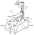
図1及び図2に示すように、本実施形態に係るはんだ溶融装置10は、基板P上のはんだの内ごく一部のはんだを溶融させることができるはんだ溶融装置であり、この装置10を利用できる基板Pは、アルミニウム基板等の高熱伝導性を有する基板であって、主として片面にはんだが存在する基板である。   As shown in FIGS. 1 and 2, the solder melting apparatus 10 according to the present embodiment is a solder melting apparatus that can melt only a part of the solder on the substrate P, and uses this apparatus 10. The possible substrate P is a substrate having high thermal conductivity, such as an aluminum substrate, and mainly having solder on one side.

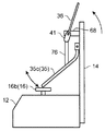
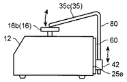
はんだ溶融装置10は、基台12と、この基台12に固定された支柱14と、基台12に支持され且つ基板Pを加熱する加熱体16と、基板Pを加熱体16に押さえ付けるための押え機構18と、基板Pを下から補助的に支持する補助支持部20と、はんだを溶融させる部位を指し示すポインタ22とを備えている。   The solder melting apparatus 10 includes a base 12, a support 14 fixed to the base 12, a heating body 16 that is supported by the base 12 and heats the substrate P, and presses the substrate P against the heating body 16. The pressing mechanism 18, an auxiliary support portion 20 that supports the substrate P from below, and a pointer 22 that points to a portion where the solder is melted.

基台12は、ケーシング25と、ケーシング25の底部25bに固定された加熱体支持部26と、を備えている。ケーシング25は、平坦な上面を有する上面部25aと、上面部25aの下方に位置する底部25bと、上面部25a及び底部25bの各前端に接続された前面部25cと、左右の側面部25dと、上面部25a及び底部25bの各後端に接続された背面部25eと、を有する。ケーシング25は、少なくとも上面部25aが磁性部材によって構成されている。上面部25aには、加熱体16を挿通させるための挿通孔25fが形成されている。前面部25cには、インジケータ25g、操作スイッチ25h等が配設されている。背面部25eには、電源スイッチ(図示省略)、電源線用インレット(図示省略)等が設けられるとともに、支柱14が固定されている。   The base 12 includes a casing 25 and a heating body support portion 26 fixed to the bottom portion 25 b of the casing 25. The casing 25 has an upper surface portion 25a having a flat upper surface, a bottom portion 25b positioned below the upper surface portion 25a, a front surface portion 25c connected to each front end of the upper surface portion 25a and the bottom portion 25b, and left and right side surface portions 25d, And a back surface portion 25e connected to each rear end of the top surface portion 25a and the bottom portion 25b. As for the casing 25, the upper surface part 25a is comprised with the magnetic member at least. An insertion hole 25f through which the heating body 16 is inserted is formed in the upper surface portion 25a. An indicator 25g, an operation switch 25h, and the like are disposed on the front surface portion 25c. A power switch (not shown), a power line inlet (not shown), and the like are provided on the back surface portion 25e, and the support column 14 is fixed.

支柱14は、ケーシング25の左右方向の中央部に配置されて、上面部25aよりも上方に延びる垂直な姿勢でケーシング25の背面部25eに固定されている。支柱14には、その長手方向に延びるように取付け溝14aが設けられている。   The support column 14 is disposed at the center portion of the casing 25 in the left-right direction, and is fixed to the back surface portion 25e of the casing 25 in a vertical posture extending upward from the upper surface portion 25a. The support column 14 is provided with a mounting groove 14a so as to extend in the longitudinal direction.

ケーシング25の内部には、前記加熱体支持部26の他に、制御基板28、電力調整部29等が配設されている。制御基板28は、前面部25cの裏面に固定されており、操作スイッチ25hの操作に応じて動作モードを切り替える制御、電源トランス等からなる電力調整部29による加熱体16への給電量の調整を行う制御等を実行する。   Inside the casing 25, in addition to the heating body support portion 26, a control board 28, a power adjustment portion 29, and the like are disposed. The control board 28 is fixed to the back surface of the front surface portion 25c, and controls the operation mode to be switched according to the operation of the operation switch 25h, and adjusts the amount of power supplied to the heating body 16 by the power adjustment unit 29 including a power transformer. The control etc. to perform are performed.

加熱体支持部26は、ケーシング25の底部25bに固定された取付け金具31と、この取付け金具31に支持されたソケット32と、を有する。取付け金具31は、一対の脚部31aと、これら脚部31aの上端部同士を接続する連結部31bとを有している。連結部31bには、加熱体16を挿通させる挿通孔31cが形成されるとともに、挿通孔31cに挿通された加熱体16を保持するニップル31dが固定されている。   The heating body support portion 26 includes a mounting bracket 31 fixed to the bottom portion 25 b of the casing 25, and a socket 32 supported by the mounting bracket 31. The mounting bracket 31 has a pair of leg portions 31a and a connecting portion 31b that connects the upper end portions of the leg portions 31a. An insertion hole 31c through which the heating body 16 is inserted is formed in the connecting portion 31b, and a nipple 31d that holds the heating body 16 inserted through the insertion hole 31c is fixed.

ソケット32は、上向きに突出したピン端子32cを有する端子部32aと、この端子部32aを囲むように配置された筒状であり、かつ端子部32aよりも上方まで延出されたグリップ部32bとを有する。グリップ部32bは、取付け金具31の連結部31bとケーシング25の底部25bとによって狭持されている。   The socket 32 has a terminal portion 32a having a pin terminal 32c protruding upward, a cylindrical shape arranged so as to surround the terminal portion 32a, and a grip portion 32b extending upward from the terminal portion 32a. Have The grip portion 32 b is sandwiched between the connecting portion 31 b of the mounting bracket 31 and the bottom portion 25 b of the casing 25.

ケーシング25の上面部25aに形成された挿通孔25f、取付け金具31の連結部31bに形成された挿通孔31cは、端子部32aの真上に位置する。このため、両挿通孔25f,31cを通して上からグリップ部32b内に加熱体16を挿入することができ、グリップ部32bに加熱体16を挿入すると、加熱体16の端子がソケット32のピン端子32cに接続される。また、ソケット32に結合された加熱体16を上向きに引っ張ることにより、加熱体16を取り外すことができる。つまり、加熱体16は、基台12に対して着脱可能である。   The insertion hole 25f formed in the upper surface portion 25a of the casing 25 and the insertion hole 31c formed in the connection portion 31b of the mounting bracket 31 are located directly above the terminal portion 32a. For this reason, the heating body 16 can be inserted into the grip portion 32b from above through both the insertion holes 25f and 31c. When the heating body 16 is inserted into the grip portion 32b, the terminal of the heating body 16 becomes the pin terminal 32c of the socket 32. Connected to. Further, the heating body 16 can be removed by pulling the heating body 16 coupled to the socket 32 upward. That is, the heating body 16 can be attached to and detached from the base 12.

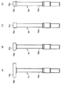
加熱体16は、一方向に延びる棒状の本体部16aと、この本体部16aの一端部(先端部)に設けられた加熱部16bとを備えている。本体部16aの基端部は、加熱体支持部26のソケット32に結合される部位であり、この基端部には、ソケット32のピン端子32cに接続される端子が設けられている。本体部16a内には図略のヒータが設けられていて、ヒータは発熱部とセンサ部を有している。このセンサ部により加熱部16bの温度を検知することができる。   The heating body 16 includes a rod-like main body portion 16a extending in one direction, and a heating portion 16b provided at one end portion (tip portion) of the main body portion 16a. The base end portion of the main body portion 16 a is a portion coupled to the socket 32 of the heating body support portion 26, and a terminal connected to the pin terminal 32 c of the socket 32 is provided at the base end portion. A heater (not shown) is provided in the main body portion 16a, and the heater has a heat generating portion and a sensor portion. The temperature of the heating unit 16b can be detected by this sensor unit.

加熱部16bは、本体部16aの長手方向に直交する方向に広がる平板円板状に形成されている。この加熱部16bは、基板Pを局所的に支え加熱するためのものであり、その上面16cは、基板Pを載置可能な平坦面となっている。   The heating part 16b is formed in a flat disk shape extending in a direction orthogonal to the longitudinal direction of the main body part 16a. The heating unit 16b is for locally supporting and heating the substrate P, and its upper surface 16c is a flat surface on which the substrate P can be placed.

本実施形態のはんだ溶融装置10は、図3(A)〜(D)に示すように、4種類の加熱体16を備えている。これらの加熱体16は、それぞれ加熱部16bの大きさが異なっており、用途・目的に応じて加熱体16を選択して使用することができる。例えば、最も大きな加熱部16bは、直径30mmの円板状に形成され、最も小さな加熱部16bは、直径が5mm程度となっている。なお、はんだ溶融装置10は、1つの加熱体16のみを備える構成であってもよい。   The solder melting apparatus 10 of this embodiment includes four types of heating bodies 16 as shown in FIGS. These heating bodies 16 have different sizes of the heating section 16b, and can be used by selecting the heating body 16 according to the application and purpose. For example, the largest heating part 16b is formed in a disk shape with a diameter of 30 mm, and the smallest heating part 16b has a diameter of about 5 mm. Note that the solder melting apparatus 10 may include only one heating body 16.

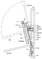
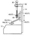
図1及び図2に示すように、基板Pを加熱体16に押さえるための押え機構18は、支柱14に取り付けられている。押え機構18は、基板Pを押圧可能な押え部35cを有する押え部材35と、押え部35cを移動させるための操作部36と、操作部36が操作されるとそれに応じて押え部35cを移動させる連動機構37と、を備えている。   As shown in FIGS. 1 and 2, the presser mechanism 18 for pressing the substrate P to the heating body 16 is attached to the support column 14. The presser mechanism 18 has a presser member 35 having a presser part 35c capable of pressing the substrate P, an operation part 36 for moving the presser part 35c, and moves the presser part 35c accordingly when the operation part 36 is operated. And an interlocking mechanism 37 to be operated.

図4及び図5に示すように、操作部36は、水平方向に延びる姿勢で配設された軸部36aと、この軸部36aの一端部につながり、軸部36aとは直交する方向に延びるレバー部36bとを備えている。   As shown in FIGS. 4 and 5, the operation portion 36 is connected to a shaft portion 36 a disposed in a horizontally extending posture, and one end portion of the shaft portion 36 a, and extends in a direction orthogonal to the shaft portion 36 a. Lever part 36b.

軸部36aは、支柱14に取り付けられた軸支部材38に保持されている。軸支部材38の一端部には、雄ねじ部38aが設けられており、この雄ねじ部38aを支柱14の取付け溝14a内に配設されたナット39に螺合することにより、軸支部材38は支柱14の所望位置に固定される。   The shaft portion 36 a is held by a shaft support member 38 attached to the support column 14. A male threaded portion 38a is provided at one end of the pivotal support member 38. By screwing the male threaded portion 38a into a nut 39 disposed in the mounting groove 14a of the support column 14, the pivotal support member 38 is provided. The column 14 is fixed at a desired position.

軸支部材38の他端部には、操作部36の軸部36aを挿通させる貫通孔が形成されている。軸部36aは、この貫通孔に挿通されることにより、左右方向に延びる姿勢で配設されるとともに、軸回りに回動可能に軸支部材38によって保持されている。   A through hole through which the shaft portion 36 a of the operation portion 36 is inserted is formed in the other end portion of the shaft support member 38. The shaft portion 36a is inserted in the through hole, thereby being disposed in a posture extending in the left-right direction, and held by a shaft support member 38 so as to be rotatable around the shaft.

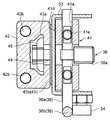
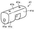
連動機構37は、操作部36の操作に応じて回動するカム41と、押え部材35を保持する保持部42と、カム41の動きを保持部42の動きに変換する伝達部材43と、を備えている。   The interlocking mechanism 37 includes a cam 41 that rotates according to the operation of the operation unit 36, a holding unit 42 that holds the pressing member 35, and a transmission member 43 that converts the movement of the cam 41 into the movement of the holding unit 42. I have.

カム41は、操作部36の軸部36aに取付けられており、カム41は軸部36aと一体的に回動する。カム41は、軸部36aの長手方向に直交する方向の断面が一方向に長い形状となっている。図6にも示すように、本実施形態においては、カム41の前記断面には、軸部36aを挿通させる貫通孔41aが形成されており、この断面における長手方向(第1方向)の一端部(図6の上端部)となる端面41bは平坦面に形成され、また前記断面における長手方向の他端部(図の下端部)となる端面41cは円弧状に形成されている。そして、カム41の前記断面において長手方向に直交する方向(幅方向;第2方向)の一端部となる側面41dが平坦面に形成されている。カム41は、第1方向の他端部(端面41c)で支柱14に反力を取りつつ後述のカバー部材53を介して第1方向の一端部(端面41b)において伝達部材43を押圧する第1姿勢と、第2方向の他端部で支柱14に反力を取りつつ後述のカバー部材53を介して第2方向の一端部(側面41d)において伝達部材43を押圧する第2姿勢とを取り得る。カム41が第1姿勢にあるときには、押え部35cは後述の押え位置となり、カム41が第2姿勢にあるときには、押え部35cは後述の退避位置となる。   The cam 41 is attached to the shaft portion 36a of the operation portion 36, and the cam 41 rotates integrally with the shaft portion 36a. The cam 41 has a shape in which a cross section in a direction orthogonal to the longitudinal direction of the shaft portion 36a is long in one direction. As shown also in FIG. 6, in this embodiment, the cross section of the cam 41 is formed with a through hole 41a through which the shaft portion 36a is inserted, and one end portion in the longitudinal direction (first direction) in this cross section. An end surface 41b to be (upper end portion in FIG. 6) is formed in a flat surface, and an end surface 41c to be the other end portion in the longitudinal direction (lower end portion in the figure) in the cross section is formed in an arc shape. And in the cross section of the cam 41, the side surface 41d used as the one end part of the direction (width direction; 2nd direction) orthogonal to a longitudinal direction is formed in the flat surface. The cam 41 presses the transmission member 43 at one end (end surface 41 b) in the first direction via a cover member 53 described later while taking a reaction force on the column 14 at the other end (end surface 41 c) in the first direction. 1 posture and a 2nd posture which presses transmission member 43 in one end part (side 41d) of the 2nd direction via cover member 53 mentioned below, taking reaction force to support 14 at the other end part of the 2nd direction. I can take it. When the cam 41 is in the first posture, the presser portion 35c is in a press position described later, and when the cam 41 is in the second posture, the presser portion 35c is in a retracted position described later.

なお、平坦面からなる端面41bと、平坦面からなる側面41dとは、本実施形態では略直交しているが、この構成に限られるものではなく、端面41b及び側面41dのなす角度は、操作部36の操作角度に応じて適宜設定される。   Note that the end surface 41b made of a flat surface and the side surface 41d made of a flat surface are substantially orthogonal in this embodiment, but the present invention is not limited to this configuration, and the angle formed by the end surface 41b and the side surface 41d is determined by the operation. It is appropriately set according to the operation angle of the unit 36.

カム41には、軸部36aを挿通させる貫通孔41aに直交するように、ねじ孔41eが設けられている。このねじ孔41eは、カム41を軸部36aに対して回動しないように固定するための虫ねじ(図示省略)を螺合させるために設けられている。   The cam 41 is provided with a screw hole 41e so as to be orthogonal to the through hole 41a through which the shaft portion 36a is inserted. The screw hole 41e is provided for screwing a bug screw (not shown) for fixing the cam 41 so as not to rotate with respect to the shaft portion 36a.

伝達部材43は、薄いSUS板等の撓みやすい板材(板ばね)によって構成されており、図4に示すように、平板状の基部43aと、この基部43aに対して折れ曲がった平板状の可動部43bとを有する。そして、伝達部材43は、基部43aが支柱14に沿うように配置されるとともに支柱14に取り付けられている。すなわち、伝達部材43は支柱14に支持されている。この状態で、伝達部材43の可動部43bは、支柱14に対して傾斜した状態となっている。   The transmission member 43 is configured by a flexible plate material (plate spring) such as a thin SUS plate, and as shown in FIG. 4, a flat plate-like base portion 43a and a flat plate-like movable portion bent with respect to the base portion 43a. 43b. And the transmission member 43 is attached to the support | pillar 14 while the base 43a is arrange | positioned along the support | pillar 14. That is, the transmission member 43 is supported by the support column 14. In this state, the movable portion 43 b of the transmission member 43 is inclined with respect to the support column 14.

可動部43bは、外力を受けることにより、折れ曲がり部位すなわち基部43a及び可動部43bの接続部位を中心として揺動する。つまり可動部43bは、カム41が第1姿勢にあるか第2姿勢にあるかに応じて弾性変形量が変わり、傾斜角度(変形角度)が変わる。   When receiving the external force, the movable portion 43b swings around a bent portion, that is, a connection portion between the base portion 43a and the movable portion 43b. That is, the movable portion 43b changes its elastic deformation amount and changes its inclination angle (deformation angle) depending on whether the cam 41 is in the first posture or the second posture.

基部43a(伝達部材43)を支柱14へ取付ける手段には、支柱14の取付け溝14a内に配設されたナット44と、支柱14との間に基部43aを挟み込む取付け板45と、ナット44に螺合することにより取付け板45を支柱14に固定するボルト46とが含まれる。ナット44は、取付け溝14a内をスライド可能であるため、ナット44を所望の位置に位置決めし、その位置でボルト46によって取付け板45を締め付けることにより、伝達部材43を所望の位置に固定することができる。伝達部材43を支柱14に固定する位置を調整することにより、押え部35cの高さ位置を調整することができる。   The means for attaching the base 43 a (transmission member 43) to the column 14 includes a nut 44 disposed in the mounting groove 14 a of the column 14, a mounting plate 45 that sandwiches the base 43 a between the column 14, and the nut 44. And a bolt 46 for fixing the mounting plate 45 to the column 14 by screwing. Since the nut 44 is slidable in the mounting groove 14a, the nut 44 is positioned at a desired position, and the mounting plate 45 is tightened by the bolt 46 at that position, thereby fixing the transmission member 43 at the desired position. Can do. By adjusting the position where the transmission member 43 is fixed to the support column 14, the height position of the presser portion 35c can be adjusted.

押え部材35は、本実施形態では、2つの押え棒35a,35aからなる。各押え棒35aは、例えば金属製であり、弾性的にたわみ変形可能となっている。各押え棒35aは、真っ直ぐな棒材を折り曲げてL字状に形成したものである。すなわち、各押え棒35aは、保持部42に保持される基側部35bと、この基側部35bの端部(下端部)に繋がり基側部35bに対して折り曲げられている押え部35cと、を有する。   In this embodiment, the presser member 35 includes two presser bars 35a and 35a. Each presser bar 35a is made of metal, for example, and can be flexibly deformed. Each presser bar 35a is formed by bending a straight bar material into an L shape. That is, each presser bar 35a includes a base side part 35b held by the holding part 42, and a presser part 35c connected to an end (lower end part) of the base side part 35b and bent with respect to the base side part 35b. Have.

各押え棒35aは保持部42に保持されている。保持部42は、伝達部材43の可動部43bに取り付けられている。保持部42には一方向に延びる取付け溝42aが設けられており、この取付け溝42a内に配設されたナット48に、伝達部材43を貫通するボルト49を締結することにより、保持部42は伝達部材43の可動部43bに固定されている。このため、保持部42は、可動部43bが揺動すると、可動部43bと一体的に動く。言い換えると、本実施形態において、保持部42は、伝達部材43の可動部43bが回動方向に動くことにより所定の動きを行う。   Each presser bar 35 a is held by the holding portion 42. The holding part 42 is attached to the movable part 43 b of the transmission member 43. The holding portion 42 is provided with a mounting groove 42a extending in one direction. By fastening a bolt 49 penetrating the transmission member 43 to a nut 48 disposed in the mounting groove 42a, the holding portion 42 is It is fixed to the movable part 43 b of the transmission member 43. For this reason, the holding part 42 moves integrally with the movable part 43b when the movable part 43b swings. In other words, in the present embodiment, the holding portion 42 performs a predetermined movement as the movable portion 43b of the transmission member 43 moves in the rotation direction.

保持部42には、略上下方向(伝達部材43の可動部43bに平行な方向)に貫通する貫通孔42b,42bが2つ形成されていて、各貫通孔42bにそれぞれ押え棒35aの基側部35bが挿通されている。したがって、押え棒35aの基側部35bは、伝達部材43の可動部43bと平行な姿勢で配設されている。   The holding portion 42 is formed with two through holes 42b and 42b penetrating in a substantially vertical direction (a direction parallel to the movable portion 43b of the transmission member 43), and the base side of the presser bar 35a is formed in each through hole 42b. The part 35b is inserted. Therefore, the base side portion 35 b of the presser bar 35 a is disposed in a posture parallel to the movable portion 43 b of the transmission member 43.

押え棒35aの基側部35bは、その上端部においてナット51によって抜け止めされている。そして、押え棒35aは、基側部35bを軸として軸回りに回動可能となっている。つまり、押え部材35は、伝達部材43の可動部43bと平行な方向に延びる軸回りに回動可能である。このため、両押え部35c,35c間の間隔を変えることができる。ただし、基側部35bは、押え部35cに横から外力が加えられない限り回動することはなく、通常の状態であれば回動しない。   The base side portion 35b of the presser bar 35a is prevented from coming off by a nut 51 at its upper end portion. The presser bar 35a is rotatable about an axis about the base side part 35b. That is, the presser member 35 can be rotated around an axis extending in a direction parallel to the movable portion 43 b of the transmission member 43. For this reason, the space | interval between both the presser parts 35c and 35c can be changed. However, the base portion 35b does not rotate unless an external force is applied from the side to the presser portion 35c, and does not rotate in a normal state.

図2に示すように、各押え棒35aの押え部35cは、その先端が加熱体16の加熱部16bの上面16cよりも低い位置となる押え位置と、押え部35cの先端が加熱体16の加熱部16bの上面16cよりも高い位置となる退避位置と、の間で移動可能である。すなわち、カム41が第1姿勢にあるときには、押え部35cは押え位置にある。そして、カム41が第1姿勢から第2姿勢になると、カム41から受ける力によって伝達部材43の可動部43bが立ち上がる方向に動くため、押え部35cは退避位置となる。カム41が第2姿勢から第1姿勢になると、伝達部材43の可動部43bは倒れる方向に動き、押え部35cは退避位置から押え位置に移動する。押え部35cが押え位置にある場合には、押え部材35の押え部35cによって基板Pを上から押さえ付けることができ、押え部35cが退避位置にある場合には、押え部35cと基板Pとの間に隙間ができる。押え部35cは、基板Pに押さえ付けられたときに弾性的に変形して基板Pを押圧する。押圧する圧力の範囲としては、本実施例では0.7〜2.6kgfが好適である。   As shown in FIG. 2, the pressing portion 35 c of each presser bar 35 a has a pressing position where the tip is lower than the upper surface 16 c of the heating portion 16 b of the heating body 16 and the tip of the pressing portion 35 c is the heating portion 16. It can move between a retracted position that is higher than the upper surface 16c of the heating unit 16b. That is, when the cam 41 is in the first posture, the presser portion 35c is in the presser position. When the cam 41 changes from the first posture to the second posture, the pressing portion 35c is in the retracted position because the movable portion 43b of the transmission member 43 is moved up by the force received from the cam 41. When the cam 41 is changed from the second posture to the first posture, the movable portion 43b of the transmission member 43 moves in the tilting direction, and the presser portion 35c moves from the retracted position to the presser position. When the presser part 35c is in the presser position, the substrate P can be pressed from above by the presser part 35c of the presser member 35. When the presser part 35c is in the retracted position, the presser part 35c and the substrate P There is a gap between them. The pressing portion 35 c elastically deforms and presses the substrate P when pressed against the substrate P. As a range of the pressure to press, 0.7-2.6 kgf is suitable in a present Example.

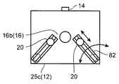
各押え棒35aの押え部35cは、加熱体16の加熱部16bから側方に位置ずれしたとこで基板Pを上から押さえ付ける。なお、基板Pが両押え部35c,35cによって押さえ付けられる部位の重心位置が加熱体16の加熱部16bの範囲内になるように、両押え棒35a,35aの向きを設定しておくことが望ましい。押え部材35が2つの押え棒35a,35aで構成される場合、例えば、各押え棒35aの押え部35cが加熱部16bの両側に分かれて配置され、各押え部35cによって押圧される部位同士を結ぶ線分の中央部が加熱部16bの範囲に収まるようにする。このようにすれば、基板Pが両押え棒35a,35aによって押さえ付けられた場合に傾くことがなく、基板Pを加熱部16b上面16cにより確実に密着させることができる。   The pressing portion 35c of each presser bar 35a presses the substrate P from above when it is displaced laterally from the heating portion 16b of the heating body 16. Note that the orientations of the presser bars 35a and 35a may be set so that the position of the center of gravity of the part where the substrate P is pressed by the presser parts 35c and 35c is within the range of the heating part 16b of the heating body 16. desirable. When the presser member 35 includes two presser bars 35a and 35a, for example, the presser parts 35c of the presser bar 35a are arranged separately on both sides of the heating part 16b, and the parts pressed by the presser parts 35c are arranged. The center part of the connecting line segment is set within the range of the heating part 16b. In this way, the substrate P can be reliably adhered to the upper surface 16c of the heating portion 16b without being inclined when the substrate P is pressed by the presser bars 35a, 35a.

なお、押え部材35は、2つの押え棒35a,35aを備えた構成に限られるものではなく、例えば、1つの部材、又は3つ以上の部材によって構成されていてもよい。押え部材35が1つの部材で構成される場合には、基板Pに接触する部位が円弧状又は環状に形成される構成であってもよい。すなわち、押さえるポイント数は1点、2点、もしくはそれ以上の数であってもよく、また押さえるポイントの形状は、点状に限られるものではなく線状であってもよい。   The pressing member 35 is not limited to the configuration including the two pressing rods 35a and 35a, and may be configured by, for example, one member or three or more members. When the pressing member 35 is formed of a single member, the portion that contacts the substrate P may be formed in an arc shape or an annular shape. That is, the number of points to be pressed may be one point, two points, or more, and the shape of the points to be pressed is not limited to a point shape but may be a linear shape.

押え機構18には、カバー部材53およびストッパ54が設けられている。カバー部材53は、カム41を覆うように設けられており、またカバー部材53には操作部36の軸部36aを挿通する挿通孔が形成されている。ストッパ54は、操作部36材が所定範囲を超えて回動することを防止すべく設けられるものであり、カバー部材53に固定されている。本実施形態では、ストッパ54はボルト及びナットによって構成されている。   The presser mechanism 18 is provided with a cover member 53 and a stopper 54. The cover member 53 is provided so as to cover the cam 41, and an insertion hole through which the shaft portion 36 a of the operation portion 36 is inserted is formed in the cover member 53. The stopper 54 is provided to prevent the operation portion 36 material from rotating beyond a predetermined range, and is fixed to the cover member 53. In the present embodiment, the stopper 54 is constituted by a bolt and a nut.

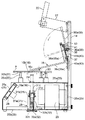
図2に示すように、加熱体16が加熱体支持部26のソケット32に保持された状態にあるときには、加熱体16の加熱部16bと基台12の上面16cとの間には隙間がある。このため、加熱体16の加熱部16b上に載置された基板Pは、基台12の上面16cから浮いた状態となる。したがって、前記補助支持部20によって基板Pを下から支持することにより、基板Pを安定した保持することができる。   As shown in FIG. 2, when the heating body 16 is held by the socket 32 of the heating body support portion 26, there is a gap between the heating portion 16 b of the heating body 16 and the upper surface 16 c of the base 12. . For this reason, the board | substrate P mounted on the heating part 16b of the heating body 16 will be in the state which floated from the upper surface 16c of the base 12. FIG. Therefore, the substrate P can be stably held by supporting the substrate P from below by the auxiliary support portion 20.

補助支持部20は、本体部20aと、この本体部20aから上方に突出した状態で本体部20aに支持された支え部20bとを備えている。支え部20bは、ばね等の弾性部材によって本体部20aに対して上下動可能である。支え部20bは、基板Pが加熱体16の加熱部16bの上面16cから浮き上がった状態で基板Pを下から補助的に支持する。そして、押え部材35の押え部35cによって基板Pを上から押さえ付けた時に支え部20bが沈み込み、基板Pが加熱部16bの上面16cに密着した状態となる。図例では、支え部20bの上端が曲面形状に構成されているが、これに限られるものでない。例えば、支え部20bの上端は平面状に形成されていてもよい。   The auxiliary support portion 20 includes a main body portion 20a and a support portion 20b supported by the main body portion 20a in a state of protruding upward from the main body portion 20a. The support portion 20b can move up and down with respect to the main body portion 20a by an elastic member such as a spring. The support part 20b supports the board | substrate P from the bottom in the state which the board | substrate P lifted from the upper surface 16c of the heating part 16b of the heating body 16. FIG. Then, when the substrate P is pressed from above by the pressing portion 35c of the pressing member 35, the support portion 20b sinks, and the substrate P comes into close contact with the upper surface 16c of the heating portion 16b. In the illustrated example, the upper end of the support portion 20b is formed in a curved surface shape, but the present invention is not limited to this. For example, the upper end of the support portion 20b may be formed in a planar shape.

補助支持部20において基板Pと接触する部分(支え部20bの先端部)は、銅等の熱伝導率の高い材質で形成されているのが好ましい。この場合、基板Pにおいて補助支持部20が接触する部分の熱が補助支持部20に伝熱しやすくなり、加熱体16に接触する部位以外での基板Pの温度を下げ易くすることができる。   The portion of the auxiliary support portion 20 that contacts the substrate P (the tip portion of the support portion 20b) is preferably formed of a material having high thermal conductivity such as copper. In this case, the heat of the portion of the substrate P that contacts the auxiliary support portion 20 is likely to be transferred to the auxiliary support portion 20, and the temperature of the substrate P other than the portion that contacts the heating body 16 can be easily lowered.

本体部20aは着磁された部材によって構成されている。このため、磁性部材によって構成されたケーシング25の上面16cに対して磁気吸着される。   The main body 20a is constituted by a magnetized member. For this reason, it is magnetically attracted to the upper surface 16c of the casing 25 made of a magnetic member.

ポインタ22は、支柱14に取り付けられた保持金具57に保持されている。保持金具57は、支柱14の取付け溝14a内に配設されたナットにボルトを螺合させることによって支柱14に固定されている。ポインタ22は例えばレーザを出射する構成である。ポインタ22は、加熱体16の加熱部16b上面16cの中心部にレーザが照射されるように保持金具57によって保持されている。   The pointer 22 is held by a holding metal fitting 57 attached to the column 14. The holding metal 57 is fixed to the column 14 by screwing a bolt into a nut disposed in the mounting groove 14 a of the column 14. The pointer 22 is configured to emit a laser, for example. The pointer 22 is held by a holding metal fitting 57 so that a laser is irradiated on the central portion of the upper surface 16c of the heating portion 16b of the heating body 16.

ここで本実施形態に係るはんだ溶融装置10の動作について簡単に説明する。このはんだ溶融装置10では、通常、操作部36は、レバー部36bが立ち上がった姿勢となっている。このとき、カム41は第2姿勢となっていて、カム41の側面41dがカバー部材53を介して伝達部材43の可動部43bを押圧している。したがって、各押え棒35aの押え部35cは退避位置となっている。   Here, operation | movement of the solder melting apparatus 10 which concerns on this embodiment is demonstrated easily. In the solder melting apparatus 10, the operation unit 36 is normally in a posture in which the lever unit 36b is raised. At this time, the cam 41 is in the second posture, and the side surface 41 d of the cam 41 presses the movable portion 43 b of the transmission member 43 via the cover member 53. Accordingly, the presser portion 35c of each presser bar 35a is in the retracted position.

この状態で、取り外したい電子部品がはんだ付けされている基板Pをセットする。すなわち、当該基板Pにおいて、取り外したい電子部品が配置された部分が加熱部16b(加熱体16)の上に位置するように基板Pを加熱体16に載置する。このとき、電子部品が配置されている側の面が上面となるように基板Pを配置する。そして、ポインタ22によってレーザが照射された部分が加熱部16b上面16cの中央部になるため、その指し示されたところに当該電子部品が位置するように基板Pの位置合わせを行う。また、補助支持部20を適宜の位置に配置する。   In this state, the board P on which the electronic component to be removed is soldered is set. That is, the board | substrate P is mounted in the heating body 16 so that the part by which the electronic component which it wants to remove in the said board | substrate P is located on the heating part 16b (heating body 16). At this time, the substrate P is disposed so that the surface on which the electronic component is disposed is the upper surface. And since the part irradiated with the laser by the pointer 22 becomes the center part of the heating part 16b upper surface 16c, the board | substrate P is aligned so that the said electronic component may be located in the pointed position. Moreover, the auxiliary | assistant support part 20 is arrange | positioned in a suitable position.

続いて、操作部36を操作して押え部35cを退避位置から押え位置に移動させる。すなわち、操作部36のレバー部36bを前に向かって倒すと、カム41は操作部36の軸部36aと一体的に回動し、第1姿勢となる。このため、伝達部材43の可動部43bがカバー部材53を介して押され、可動部43bは保持部42とともに前側に少し傾倒する。これにより、押え部35cが退避位置から押え位置に移動して基板Pを上から押さえ付ける。これにより、基板Pは、補助支持部20によって補助的に支えられつつ、加熱体16の加熱部16bに押し付けられて密着する。このとき、各押え棒35aを基側部35bを軸として回動して、押え部35cを適宜の位置に調整する。   Subsequently, the operation portion 36 is operated to move the presser portion 35c from the retracted position to the presser position. That is, when the lever portion 36b of the operation portion 36 is tilted forward, the cam 41 rotates integrally with the shaft portion 36a of the operation portion 36 and assumes the first posture. For this reason, the movable part 43 b of the transmission member 43 is pushed through the cover member 53, and the movable part 43 b is slightly tilted forward together with the holding part 42. As a result, the pressing portion 35c moves from the retracted position to the pressing position and presses the substrate P from above. As a result, the substrate P is pressed against the heating unit 16b of the heating body 16 and is in close contact with the substrate P while being supplementarily supported by the auxiliary support unit 20. At this time, each presser bar 35a is rotated about the base side part 35b, and the presser part 35c is adjusted to an appropriate position.

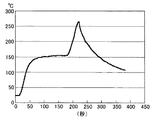
加熱体16は、予め記憶されている温度プロファイルに従って基板Pを加熱する。例えば、150〜180℃に基板P温度を維持する予備加熱を行った後、220〜260℃程度で本加熱を行う。図19は、推奨されている温度プロファイルになるように設定して基板P上面温度を測定した結果の一例である。押え部35cで基板Pを上から押さえ付けて本加熱した後、操作部36を操作し、押え部35cを退避側に移動させた。図19に示されるように、本加熱終了後、加熱体16の上面16cへの基板Pの押さえ付けを解除するため、基板Pの上面温度を速やかに下げることが可能である。押え機構18による押え付けを解除しない場合には、温度プロファイルに示された冷却ラインより時間のかかるものになる。押え機構18による押さえ付けを解除することにより、本加熱後の熱を速やかに下げ、部品への熱影響を少なくすることができる。   The heating body 16 heats the substrate P according to a temperature profile stored in advance. For example, after preheating to maintain the substrate P temperature at 150 to 180 ° C., the main heating is performed at about 220 to 260 ° C. FIG. 19 shows an example of the result of measuring the temperature of the upper surface of the substrate P by setting it to a recommended temperature profile. After the substrate P was pressed from above by the pressing portion 35c and the main heating was performed, the operation portion 36 was operated to move the pressing portion 35c to the retreat side. As shown in FIG. 19, after the main heating is completed, the upper surface temperature of the substrate P can be quickly lowered to release the pressing of the substrate P on the upper surface 16 c of the heating body 16. If the presser mechanism 18 does not release the presser, it takes more time than the cooling line indicated in the temperature profile. By releasing the pressing by the presser mechanism 18, the heat after the main heating can be quickly reduced, and the thermal influence on the parts can be reduced.

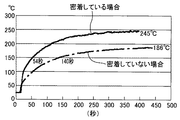
なお、図20に示すように、基板Pを加熱体16に密着させる場合と、密着させない場合とで、安定状態に達するまでの時間に差が生じること、安定状態での温度に差が生じることを確認できている。密着していない場合での安定状態に達した基板P温度が例えば186℃であるのに対し、押え部35cによって基板Pを押さえ付け、基板Pと加熱体16の上面16cとを密着させた場合には、例えば245℃まで上昇する。また、立ち上がりから150℃に達する時間は、密着していない場合が140秒であるのに対し、密着した場合は54秒となっており、基板Pを加熱体16に密着させることより、より短時間で加熱できることが確認できている。この温度は押え部35cと加熱体16との間の位置での基板表面の測定結果である。この結果より、押え部35cにより基板Pを加熱体16の上面に密着するように上から押さえ付けた場合は効率的な加熱が可能であり、加熱によるはんだ溶融後、押え部35cによる押さえ付けを緩めることによって押さえ付けの密着を緩め、基板P上の部品の温度を速やかに下げることができることがわかる。   Note that, as shown in FIG. 20, there is a difference in the time to reach the stable state and a difference in the temperature in the stable state between the case where the substrate P is brought into close contact with the heating body 16 and the case where the substrate P is not brought into close contact. Has been confirmed. When the temperature of the substrate P that has reached a stable state when it is not in contact is 186 ° C., for example, the substrate P is pressed by the holding portion 35c, and the substrate P and the upper surface 16c of the heating body 16 are in close contact with each other. For example, the temperature rises to 245 ° C. Further, the time to reach 150 ° C. from the rising time is 140 seconds when not closely contacting, but 54 seconds when closely contacting, and is shorter than when the substrate P is closely contacted with the heating body 16. It has been confirmed that it can be heated in time. This temperature is a measurement result of the substrate surface at a position between the pressing portion 35 c and the heating body 16. From this result, when the substrate P is pressed from above so as to be in close contact with the upper surface of the heating body 16 by the pressing portion 35c, efficient heating is possible. After the solder is melted by heating, the pressing by the pressing portion 35c is performed. It can be seen that by loosening, the pressing contact can be loosened, and the temperature of the components on the substrate P can be lowered quickly.

所定の温度プロファイルに従って基板Pが加熱されると、加熱部16bのすぐ上に位置するはんだが溶融して電子部品を取り外すことができる。なお、電子部品が実装されていない部分にクリームはんだを塗布し電子部品を装着した上で加熱しはんだ付けを行うこともできる。   When the substrate P is heated according to the predetermined temperature profile, the solder located immediately above the heating unit 16b is melted and the electronic component can be removed. Note that soldering can be performed by applying cream solder to a portion where the electronic component is not mounted and mounting the electronic component, followed by heating.

以上説明したように、本実施形態では、加熱体16の上面16cに基板Pが載置されると、この基板Pは基台12の上面に対して浮いた状態となり、基板Pと基台12の上面との間には間隙ができる。このとき、加熱体16の上面16cは、載置される基板Pの大きさに比べると小さくなっているため、加熱体16の上面16cは一部のはんだが位置する所定部位の基板の下側を支え、基板Pは加熱体16によって局所的に支えられて加熱されることになる。この時、一部のはんだが位置する基板Pの下側の中心点と加熱体16の上面16cの中心点を一致させた点で加熱し、支えることができる。すなわち、溶融したいはんだの真下の位置に加熱体16の上面16cをもってくることができる。したがって、基板P上の一部のはんだのみを溶融させることができる。このため、基板Pに実装された電子部品のうち一部の電子部品を取り外すような場合でも、このはんだ溶融装置10を使用することができる。したがって、取り外さない部品への熱影響も避けることができる。   As described above, in this embodiment, when the substrate P is placed on the upper surface 16 c of the heating body 16, the substrate P floats with respect to the upper surface of the base 12, and the substrate P and the base 12 There is a gap between the upper surface of the substrate. At this time, since the upper surface 16c of the heating body 16 is smaller than the size of the substrate P to be placed, the upper surface 16c of the heating body 16 is the lower side of the substrate at a predetermined portion where a part of solder is located. The substrate P is locally supported by the heating body 16 and heated. At this time, it is possible to heat and support at a point where the center point on the lower side of the substrate P where a part of the solder is located and the center point of the upper surface 16c of the heating body 16 are matched. That is, the upper surface 16c of the heating body 16 can be brought to a position directly below the solder to be melted. Therefore, only a part of the solder on the substrate P can be melted. For this reason, the solder melting apparatus 10 can be used even when some of the electronic components mounted on the substrate P are removed. Therefore, it is possible to avoid the thermal influence on the parts that are not removed.

しかも本実施形態では、加熱体16の上面16c位置から側方に位置ずれしたところを押え部35cによって上から押さえ付け、この状態で基板Pを加熱する。すなわち、加熱体16の上面16c位置から側方に位置ずれしたところを上から押さえるが、このとき基板Pが傾くことなく加熱体16の上面16cに密着するように基板Pを押さえる。したがって、加熱体16の熱を効果的に基板Pの所望部位に伝えることができる。   In addition, in the present embodiment, the position shifted from the position of the upper surface 16c of the heating body 16 to the side is pressed from above by the pressing portion 35c, and the substrate P is heated in this state. That is, the position displaced laterally from the position of the upper surface 16c of the heating body 16 is pressed from above, but at this time, the substrate P is pressed so as to be in close contact with the upper surface 16c of the heating body 16. Therefore, the heat of the heating body 16 can be effectively transmitted to a desired portion of the substrate P.

また本実施形態では、押え部35cを押え位置に位置させて加熱体16によって基板Pを加熱することにより、基板P上において加熱体16の上方に位置するはんだを溶融させることができる。一方、押え部35cを退避位置に移動させることにより、基板Pを加熱体16上にセットするとき、又は基板Pを加熱体16から取り外すときに押え部35cが邪魔にならないようにすることができる。   Moreover, in this embodiment, the solder located on the board | substrate P above the heating body 16 can be fuse | melted by positioning the holding | suppressing part 35c in a pressing position and heating the board | substrate P with the heating body 16. FIG. On the other hand, by moving the presser part 35c to the retracted position, the presser part 35c can be kept out of the way when the substrate P is set on the heating body 16 or when the substrate P is removed from the heating body 16. .

さらに本実施形態では、操作部36が操作されることにより、押え部35cが移動する。すなわち、操作部36を操作すると、退避位置にあった押え部35cを押え位置まで移動させることができ、また操作部36を操作すると、押え位置にあった押え部35cを退避位置まで移動させることができる。このため、基板Pを加熱部16b上にセットする作業、および基板Pを取り外す作業を楽に行うことができる。   Further, in the present embodiment, when the operation unit 36 is operated, the presser unit 35c moves. That is, when the operation unit 36 is operated, the presser part 35c at the retracted position can be moved to the presser position, and when the operation part 36 is operated, the presser part 35c at the presser position is moved to the retracted position. Can do. For this reason, the operation | work which sets the board | substrate P on the heating part 16b, and the operation | work which removes the board | substrate P can be performed easily.

また本実施形態では、押え部35cが基板Pを加熱体16に押さえ付ける際に弾性的に変形し、この弾性力によって基板Pを押圧する。このため、異なる厚みの基板Pに対しても基板Pを押さえ付けることができる。   In the present embodiment, the pressing portion 35c is elastically deformed when pressing the substrate P against the heating body 16, and the substrate P is pressed by this elastic force. For this reason, the substrate P can be pressed against the substrates P having different thicknesses.

また本実施形態では、基板Pが加熱体16上に載置されたとき、基台12の上面から浮いている部分を補助支持部20によって下から支持するため、基板Pの全体をより安定した状態に保持することができる。また、加熱体16の上面16cの面積が小さい場合でも、基板Pを安定させることができるので、より小さな面積で基板Pを加熱することが可能となる。このため、ごく小さな面積のはんだを溶融する場合にもこのはんだ溶融装置10を使用することができる。   Moreover, in this embodiment, when the board | substrate P was mounted on the heating body 16, since the part which floated from the upper surface of the base 12 is supported from the bottom by the auxiliary | assistant support part 20, the whole board | substrate P was stabilized more. Can be kept in a state. Moreover, even when the area of the upper surface 16c of the heating body 16 is small, the substrate P can be stabilized, so that the substrate P can be heated with a smaller area. For this reason, the solder melting apparatus 10 can be used even when a very small area of solder is melted.

しかも本実施形態では、補助支持部20が基台12の上面に磁気吸着される構成となっているので、補助支持部20を基台12の上面の所望の位置に配置でき、しかもどの位置においても補助支持部20を磁力で固定することができる。   Moreover, in the present embodiment, since the auxiliary support portion 20 is magnetically attracted to the upper surface of the base 12, the auxiliary support portion 20 can be disposed at a desired position on the upper surface of the base 12, and at any position. Also, the auxiliary support portion 20 can be fixed by a magnetic force.

また本実施形態では、加熱体16が基台12に対して着脱可能となっている。このため、上面16cの大きさの異なる複数の加熱体16を用意することにより、目的に応じた適切な大きさの上面16cを有する加熱体16を基台12に取り付けて使用することができる。すなわち、加熱体16を交換可能にすることができ、より汎用性の高いはんだ溶融装置10とすることができる。   In the present embodiment, the heating body 16 is detachable from the base 12. For this reason, by preparing the several heating body 16 from which the magnitude | size of the upper surface 16c differs, the heating body 16 which has the upper surface 16c of the suitable magnitude | size according to the objective can be attached to the base 12, and can be used. That is, the heating body 16 can be replaced, and the solder melting apparatus 10 having higher versatility can be obtained.

なお、本発明は、前記実施形態に限られるものではなく、その趣旨を逸脱しない範囲で種々変更、改良等が可能である。例えば、前記実施形態では、保持部42が水平軸回りに回動する構成としたが、図7に示すように、保持部42が上下方向に直線的に移動する構成としてもよい。   Note that the present invention is not limited to the above-described embodiment, and various modifications and improvements can be made without departing from the spirit of the present invention. For example, in the above-described embodiment, the holding portion 42 is configured to rotate around the horizontal axis. However, as illustrated in FIG. 7, the holding portion 42 may be configured to linearly move in the vertical direction.

この構成では、連動機構37は、操作部36の操作に応じて回動するカム41と、上下方向に延びるレール部材60と、押え部材35を保持し且つレール部材60に沿ってスライド可能な保持部42と、を備え、カム41が回動することによって保持部42がレール部材60に沿って移動する。具体的には、支柱14には、その長さ方向に延びるレール部材60が固定されており、保持部42は、レール部材60に係合した状態を維持しながら上下方向にスライド可能となっている。   In this configuration, the interlocking mechanism 37 holds the cam 41 that rotates according to the operation of the operation unit 36, the rail member 60 that extends in the vertical direction, and the presser member 35 and is slidable along the rail member 60. Part 42, and the holding part 42 moves along the rail member 60 when the cam 41 rotates. Specifically, a rail member 60 extending in the length direction is fixed to the support column 14, and the holding portion 42 is slidable in the vertical direction while maintaining the state engaged with the rail member 60. Yes.

カム41は、支柱14に回動可能に設けられており、操作部36の操作に伴って水平軸回りに回動する。カム41は、保持部42の上端面に当接可能となっている。操作部36を上向きに操作すると、カム41が保持部42を下方に押圧し、これにより、保持部42が下方に移動し、押え部35cが退避位置から押え位置に移動する。   The cam 41 is rotatably provided on the support column 14 and rotates about the horizontal axis in accordance with the operation of the operation unit 36. The cam 41 can come into contact with the upper end surface of the holding portion 42. When the operation unit 36 is operated upward, the cam 41 presses the holding unit 42 downward, whereby the holding unit 42 moves downward, and the pressing unit 35c moves from the retracted position to the pressing position.

保持部42には、当該保持部を上向きに付勢する付勢部材61が設けられている。したがって、操作部36から手を離すと押え部35cは上昇して、退避位置に戻る。   The holding portion 42 is provided with a biasing member 61 that biases the holding portion upward. Therefore, when the hand is released from the operation portion 36, the presser portion 35c is raised and returned to the retracted position.

なお、カム41の先端部近傍に平坦面を形成しておき、この平坦面が保持部42の上端面に面接触することにより、保持部42が下位置で保持される構成としてもよい。この場合には、操作部36を下向きに回動することにより、保持部42を付勢部材61のばね力によって上昇させる構成となる。この態様では、押え部35cが押え位置にあるときに基板Pを押さえ付けた状態を確実に維持することができる。この結果、加熱体16で基板Pを加熱するときに、加熱体16の上面16cが基板Pに密着した状態を確実に維持することができる。また、押え部35cの重量を軽くしたとしても、押え部35cで確実に基板Pを押さえ付けることができる。このため、押え部35cが手動で移動する構成の場合には、押え部35cを軽量化することにより操作性のよい押え機構18にすることができる。   A configuration may be adopted in which a flat surface is formed in the vicinity of the distal end portion of the cam 41, and the holding portion 42 is held at the lower position by making the flat surface come into surface contact with the upper end surface of the holding portion 42. In this case, the holding portion 42 is raised by the spring force of the biasing member 61 by rotating the operation portion 36 downward. In this aspect, it is possible to reliably maintain the state in which the substrate P is pressed when the pressing portion 35c is in the pressing position. As a result, when the substrate P is heated by the heating body 16, the state where the upper surface 16c of the heating body 16 is in close contact with the substrate P can be reliably maintained. Even if the weight of the holding portion 35c is reduced, the substrate P can be reliably pressed by the holding portion 35c. For this reason, in the case of a structure in which the presser part 35c is manually moved, the presser mechanism 18 having good operability can be obtained by reducing the weight of the presser part 35c.

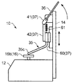
図7では、連動機構37がカム41を有する構成としているが、これに限られるものではない。例えば、図8に示すように、連動機構37は、操作部36の操作に応じて上下動する伝達部材43と、上下方向に延びるレール部材60と、押え部材35を保持し且つレール部材60に沿ってスライド可能な保持部42と、を備え、伝達部材43が上下方向に移動することによって保持部42がレール部材60に沿って移動する。すなわち、操作部36にはピニオン63が固定されており、伝達部材43は、このピニオン63に噛み合い且つ保持部42に結合されたラック64を有している。そして、操作部36を水平軸回りに回動すると、ラック64が上下方向に移動する。これにより、押え部35cを退避位置と押え位置との間で移動させることができる。   In FIG. 7, the interlocking mechanism 37 has a cam 41, but the present invention is not limited to this. For example, as shown in FIG. 8, the interlocking mechanism 37 holds the transmission member 43 that moves up and down in response to the operation of the operation unit 36, the rail member 60 that extends in the up and down direction, and the presser member 35 and is attached to the rail member 60. And a holding part 42 slidable along the rail. The holding part 42 moves along the rail member 60 when the transmission member 43 moves in the vertical direction. That is, a pinion 63 is fixed to the operation portion 36, and the transmission member 43 has a rack 64 that meshes with the pinion 63 and is coupled to the holding portion 42. And if the operation part 36 is rotated around a horizontal axis, the rack 64 will move to an up-down direction. Thereby, the presser part 35c can be moved between the retracted position and the presser position.

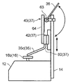
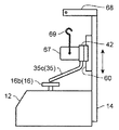
また、図9に示すように、操作部36を垂直軸回りに回動可能な構成としてもよい。この構成では、操作部36は、支柱14から側方に延出した延出部68に垂直軸回りに回動可能に保持されている。この操作部36には雄ねじ部65が設けられており、伝達部材43は、この雄ねじ部65に螺合する雌ねじ部を有している。そして、操作部36を軸回りに回動する操作を行うことにより、保持部42が上下方向に移動する。これにより、押え部35cを退避位置と押え位置との間で移動させることができる。この構成では、保持部42を任意の位置で固定できるので、基板Pを押さえ付けた状態を確実に維持することができる。この結果、加熱体16で基板Pを加熱するときに、加熱体16の上面16cが基板Pに密着した状態を確実に維持することができる。また、押え部35cの重量を軽くしたとしても、押え部35cで確実に基板Pを押さえ付けることができる。   Further, as shown in FIG. 9, the operation unit 36 may be configured to be rotatable about a vertical axis. In this configuration, the operation unit 36 is held by an extending portion 68 extending laterally from the support column 14 so as to be rotatable about a vertical axis. The operating portion 36 is provided with a male screw portion 65, and the transmission member 43 has a female screw portion that engages with the male screw portion 65. And the holding part 42 moves to an up-down direction by performing operation which rotates the operation part 36 around an axis | shaft. Thereby, the presser part 35c can be moved between the retracted position and the presser position. In this configuration, the holding portion 42 can be fixed at an arbitrary position, so that the state where the substrate P is pressed can be reliably maintained. As a result, when the substrate P is heated by the heating body 16, the state where the upper surface 16c of the heating body 16 is in close contact with the substrate P can be reliably maintained. Even if the weight of the holding portion 35c is reduced, the substrate P can be reliably pressed by the holding portion 35c.

前記実施形態では、操作部36及び連動機構37が設けられた構成について説明したが、これに限られるものではない。例えば、図10に示すように、保持部42を操作部36に連動して移動させるのではなく、保持部42自体を移動させる構成としてもよい。すなわち、支柱14には上下方向に延びるレール部材60が設けられており、保持部42は、押え部材35を保持し且つレール部材60に沿ってスライド可能となっている。保持部42には、錘67が固定されるとともに、錘67には、支柱14から延出された延出部68に引っ掛けるためのフック69が固定されている。フック69が延出部68に引っ掛けられると、押え部35cは退避位置に維持される。一方、フック69を外すと、押え部35cは退避位置から押え位置まで降下する。この構成では、ストロークに限らず、一体荷重で基板Pを押圧することができる。   In the above-described embodiment, the configuration in which the operation unit 36 and the interlocking mechanism 37 are provided has been described, but the configuration is not limited thereto. For example, as shown in FIG. 10, the holding unit 42 may be moved instead of being moved in conjunction with the operation unit 36. That is, the support member 14 is provided with a rail member 60 extending in the vertical direction, and the holding portion 42 holds the pressing member 35 and is slidable along the rail member 60. A weight 67 is fixed to the holding portion 42, and a hook 69 for being hooked on the extension portion 68 extending from the support column 14 is fixed to the weight 67. When the hook 69 is hooked on the extending portion 68, the presser portion 35c is maintained at the retracted position. On the other hand, when the hook 69 is removed, the presser part 35c is lowered from the retracted position to the presser position. In this configuration, the substrate P can be pressed with an integral load, not limited to the stroke.

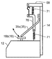
また、図11に示すように、錘67に代えてばね部材71の弾性力を利用してもよい。この構成は、保持部42と支柱14から延出された支持部72との間に配置されたばね部材71が設けられる。このばね部材71は保持部42を下向きに付勢している。ばね部材71が図11に示すように保持部42の上側に配置される場合には、ばね部材71は圧縮ばねとなり、保持部42の下側で基台12との間に配置される場合には、ばね部材71は引張ばねとなる。なお、ばね部材71に代えてシリンダ(図示省略)を備える構成としてもよい。   Further, as shown in FIG. 11, the elastic force of the spring member 71 may be used instead of the weight 67. In this configuration, the spring member 71 is provided between the holding portion 42 and the support portion 72 extending from the support column 14. The spring member 71 urges the holding portion 42 downward. When the spring member 71 is arranged on the upper side of the holding portion 42 as shown in FIG. 11, the spring member 71 becomes a compression spring and is arranged between the base 12 and the lower side of the holding portion 42. The spring member 71 is a tension spring. In addition, it is good also as a structure provided instead of the spring member 71 with a cylinder (illustration omitted).

図8〜図11に示す構成のように、押え部材35がレール部材60に沿って上下方向に移動する構成に代え、図12〜図15に示すように、押え部材35が支柱14に回動可能に支持される構成としてもよい。   As shown in FIGS. 8 to 11, instead of the structure in which the presser member 35 moves in the vertical direction along the rail member 60, the presser member 35 rotates to the column 14 as shown in FIGS. 12 to 15. It is good also as a structure supported so that it is possible.

図12に示す構成では、押え部材35の上端部が支柱14に回動可能に取り付けられている。したがって、押え部材35が上端部を中心として回動することにより、押え部材35の押え部35cは押え位置と退避位置との間で移動する。支柱14の延出部68には、押圧部材としての錘67を引っ掛けることができ、この錘67はばね部材74によって延出部68につり下げられている。したがって、錘67を延出部68から外すと錘67の自重によって押え部35cを下方に押すことができる。   In the configuration shown in FIG. 12, the upper end portion of the pressing member 35 is rotatably attached to the support column 14. Therefore, when the presser member 35 rotates around the upper end, the presser part 35c of the presser member 35 moves between the presser position and the retracted position. A weight 67 as a pressing member can be hooked on the extending portion 68 of the column 14, and the weight 67 is suspended from the extending portion 68 by a spring member 74. Therefore, when the weight 67 is removed from the extending portion 68, the presser portion 35c can be pushed downward by the weight of the weight 67.

図13に示す構成では、押圧部材76がばね部材71のばね力によって押え部材35を下方に押圧する。図12のばね部材74は錘67をつり下げるために用いられるが、図13に示す構成では、押え部材35の押え部35cを下方に付勢するためにばね部材71が用いられる。ばね部材71が押圧部材76の上端に設けられるときには、ばね部材71として圧縮ばねが用いられ、ばね部材71が押圧部材76の下端に設けられるときには、ばね部材71として引張ばねが用いられる。図13では両ばね部材71が用いられた構成を示しているが、何れか一方のみでよい。なお、ばね部材71に代えて、シリンダ(図示省略)を用いてもよい。   In the configuration shown in FIG. 13, the pressing member 76 presses the pressing member 35 downward by the spring force of the spring member 71. The spring member 74 in FIG. 12 is used to suspend the weight 67, but in the configuration shown in FIG. 13, the spring member 71 is used to urge the presser portion 35c of the presser member 35 downward. When the spring member 71 is provided at the upper end of the pressing member 76, a compression spring is used as the spring member 71. When the spring member 71 is provided at the lower end of the pressing member 76, a tension spring is used as the spring member 71. Although FIG. 13 shows a configuration in which both spring members 71 are used, only one of them may be used. Instead of the spring member 71, a cylinder (not shown) may be used.

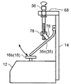
図14に示す構成では、操作部36を垂直軸回りに回転させるとナット部材78が上下動し、押圧部材76によって押え部材35を押圧する構成である。ナット部材78は図略の案内手段によって上下方向に案内される。   In the configuration shown in FIG. 14, when the operation unit 36 is rotated around the vertical axis, the nut member 78 moves up and down and the pressing member 76 is pressed by the pressing member 76. The nut member 78 is guided in the vertical direction by guide means (not shown).

図15に示す構成では、操作部36に固定されたカム41を回動させることによって、押圧部材76を介して押え部材35を押圧する構成である。この押圧部材76も図略の案内手段によって上下方向に案内される。   In the configuration shown in FIG. 15, the pressing member 35 is pressed via the pressing member 76 by rotating the cam 41 fixed to the operation unit 36. This pressing member 76 is also guided in the vertical direction by a guide means (not shown).

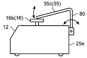
図8〜図11の構成は、押え部材35が支柱14に設けられたレール部材60に沿って上下方向に移動する構成としたが、これに限られるものではない。例えば、図16に示すように、レール部材60を基台12の背面部25eに固定し、押え部材35が上方に延びる延出部80を備え、押え部35cがこの延出部80の上端部に繋がる構成としてもよい。   8 to 11 is configured such that the presser member 35 moves in the vertical direction along the rail member 60 provided on the support column 14, but is not limited thereto. For example, as shown in FIG. 16, the rail member 60 is fixed to the back surface portion 25 e of the base 12, the pressing member 35 includes an extending portion 80 that extends upward, and the pressing portion 35 c is the upper end portion of the extending portion 80. It is good also as a structure connected to.

また、図17に示すように、押え部材35が上下方向に延びる延出部80の下端部において、基台12の背面部25eに回動可能に支持される構成としてもよい。   Moreover, as shown in FIG. 17, it is good also as a structure by which the pressing member 35 is rotatably supported by the back surface part 25e of the base 12, in the lower end part of the extension part 80 extended in an up-down direction.

前記実施形態では、補助支持部20が基台12の上面の任意の位置に配置されるとともに、基台12から取り外す構成としたが、これに限られるものではない。例えば、図18に示すように、基台12の上面16cにはレール82が設けられていて、補助支持部20はこのレール82に案内される構成としてもよい。この構成において、補助支持部20をレール82から取り外せない構成としてもよい。レール82はその一端部において基台12の上面25aに回動可能に取り付けられている。したがって、補助支持部20の配置の自由度が阻害されることを防止できる。   In the embodiment, the auxiliary support portion 20 is arranged at an arbitrary position on the upper surface of the base 12 and is detached from the base 12. However, the present invention is not limited to this. For example, as shown in FIG. 18, a rail 82 may be provided on the upper surface 16 c of the base 12, and the auxiliary support portion 20 may be guided by the rail 82. In this configuration, the auxiliary support portion 20 may not be removed from the rail 82. The rail 82 is rotatably attached to the upper surface 25a of the base 12 at one end thereof. Therefore, it can prevent that the freedom degree of arrangement | positioning of the auxiliary | assistant support part 20 is inhibited.

10 溶融装置
12 基台
14 支柱
14a 取付け溝
16 加熱体
16b 加熱部
16c 上面
18 押え機構
20 補助支持部
22 ポインタ
25 ケーシング
25a 上面部
25b 底部
25c 前面部
25d 側面部
25e 背面部
26 加熱体支持部
35 押え部材
35a 押え棒
35b 基側部
35c 押え部
36 操作部
37 連動機構
41 カム
41b 端面
41c 端面
41d 側面
42 保持部
43 伝達部材
43a 基部
43b 可動部
60 レール部材
61 付勢部材
82 レール
DESCRIPTION OF SYMBOLS 10 Melting | fusing apparatus 12 Base 14 Support | pillar 14a Mounting groove 16 Heating body 16b Heating part 16c Upper surface 18 Holding mechanism 20 Auxiliary support part 22 Pointer 25 Casing 25a Upper surface part 25b Bottom part 25c Front part 25d Side part 25e Rear part 26 Heating body support part 35 Presser member 35a Presser bar 35b Base side part 35c Presser part 36 Operation part 37 Interlocking mechanism 41 Cam 41b End face 41c End face 41d Side face 42 Holding part 43 Transmission member 43a Base part 43b Movable part 60 Rail member 61 Energizing member 82 Rail

Claims (11)

基板を局所的に加熱して、前記基板上の一部のはんだを溶融させるためのはんだ溶融装置であって、
前記一部のはんだが位置する所定部位の基板の下側を支え、加熱する上面を有する加熱体と、
前記加熱体の前記上面よりも下方に位置する上面を有する基台と、を備え、
前記加熱体の前記上面には、当該上面よりも大きな前記基板が載置され、前記基板を局所的に加熱するはんだ溶融装置。
A solder melting apparatus for locally heating a substrate to melt a part of solder on the substrate,
A heating body having an upper surface for supporting and heating the lower side of the substrate at a predetermined portion where the part of the solder is located;
A base having an upper surface located below the upper surface of the heating body,
A solder melting apparatus in which the substrate larger than the upper surface is placed on the upper surface of the heating body and locally heats the substrate.
前記加熱体の前記上面に載せられた前記基板を前記加熱体に対して押さえ付けるための押え機構を備えており、
前記押え機構は、前記基板に押さえ付けられる押え部を有し、この押え部によって前記基板が前記加熱体の前記上面に密着するように、前記押え部によって前記基板を上から押さえ付ける請求項1に記載のはんだ溶融装置。
A presser mechanism for pressing the substrate placed on the upper surface of the heating body against the heating body;
The presser mechanism has a presser part that is pressed against the substrate, and the presser part presses the substrate from above so that the presser part is in close contact with the upper surface of the heating body. The solder melting apparatus described in 1.
前記押え機構は、前記基板を上から押さえる押え位置と、この押え位置から前記押え部を退避させる退避位置との間で、前記押え部を移動可能に構成されている請求項2に記載のはんだ溶融装置。   3. The solder according to claim 2, wherein the presser mechanism is configured to be able to move the presser part between a presser position where the substrate is pressed from above and a retreat position where the presser part is retracted from the presser position. Melting equipment. 前記押え機構は、前記押え部を移動させるための操作部と、前記操作部が操作されるとそれに応じて前記押え部を移動させる連動機構と、を備えている請求項3に記載のはんだ溶融装置。   The solder press according to claim 3, wherein the presser mechanism includes an operation part for moving the presser part, and an interlocking mechanism for moving the presser part in response to the operation part being operated. apparatus. 前記押え部は、弾性的に変形する材質で構成されるとともに、前記基板に押さえ付けられたときに弾性的に変形して前記基板を押圧する請求項2〜4の何れか1項に記載のはんだ溶融装置。   The said holding part is comprised with the material which deform | transforms elastically, and when it presses against the said board | substrate, it deform | transforms elastically and presses the said board | substrate. Solder melting device. 前記基台の前記上面上に配置され、前記加熱体の前記上面から側方に位置ずれしたところで前記基板を下から支持する補助支持部を備えている請求項1〜5の何れか1項に記載のはんだ溶融装置。   The auxiliary support part which is arrange | positioned on the said upper surface of the said base and supports the said board | substrate from the bottom in the position shifted laterally from the said upper surface of the said heating body is provided in any one of Claims 1-5. The solder melting apparatus as described. 前記基台の前記上面は磁性部材によって構成されており、
前記補助支持部は、前記基台の前記上面に磁気吸着される請求項6に記載のはんだ溶融装置。
The upper surface of the base is made of a magnetic member,
The solder melting apparatus according to claim 6, wherein the auxiliary support portion is magnetically attracted to the upper surface of the base.
前記補助支持部は、弾性部材により上下動可能な支え部を有する請求項7に記載のはんだ溶融装置。   The solder melting apparatus according to claim 7, wherein the auxiliary support portion has a support portion that can be moved up and down by an elastic member. 前記基台の前記上面には、前記補助支持部を案内するレールが設けられている請求項6に記載のはんだ溶融装置。   The solder melting apparatus according to claim 6, wherein a rail for guiding the auxiliary support portion is provided on the upper surface of the base. 前記加熱体は、前記基台に対して着脱可能である請求項1〜9の何れか1項に記載のはんだ溶融装置。   The solder melting apparatus according to claim 1, wherein the heating body is detachable from the base. 前記加熱体を複数備えており、これら加熱体は前記上面の大きさが異なっていて、選択的に使用される請求項10に記載のはんだ溶融装置。   The solder melting apparatus according to claim 10, comprising a plurality of the heating bodies, wherein the heating bodies have different sizes on the upper surface and are selectively used.
JP2011050456A 2011-03-08 2011-03-08 Solder melting device Pending JP2012190830A (en)

Priority Applications (1)

Application Number Priority Date Filing Date Title
JP2011050456A JP2012190830A (en) 2011-03-08 2011-03-08 Solder melting device

Applications Claiming Priority (1)

Application Number Priority Date Filing Date Title
JP2011050456A JP2012190830A (en) 2011-03-08 2011-03-08 Solder melting device

Publications (1)

Publication Number Publication Date
JP2012190830A true JP2012190830A (en) 2012-10-04

Family

ID=47083723

Family Applications (1)

Application Number Title Priority Date Filing Date
JP2011050456A Pending JP2012190830A (en) 2011-03-08 2011-03-08 Solder melting device

Country Status (1)

Country Link
JP (1) JP2012190830A (en)

Citations (3)

* Cited by examiner, † Cited by third party
Publication number Priority date Publication date Assignee Title
JPS625682U (en) * 1985-06-26 1987-01-14
JP2006093243A (en) * 2004-09-21 2006-04-06 Juki Corp Electronic component mounting equipment
JP2006245471A (en) * 2005-03-07 2006-09-14 Matsushita Electric Ind Co Ltd Electronic component joining apparatus and joining method

Patent Citations (3)

* Cited by examiner, † Cited by third party
Publication number Priority date Publication date Assignee Title
JPS625682U (en) * 1985-06-26 1987-01-14
JP2006093243A (en) * 2004-09-21 2006-04-06 Juki Corp Electronic component mounting equipment
JP2006245471A (en) * 2005-03-07 2006-09-14 Matsushita Electric Ind Co Ltd Electronic component joining apparatus and joining method

Similar Documents

Publication Publication Date Title
JP2015128787A (en) TIG welding apparatus and TIG welding method
CN107405712B (en) Solder processing equipment
JP2010512656A (en) Handling device for components, in particular electrical components
CN101314193A (en) Processing Equipment
JP5288012B2 (en) Jet solder height confirmation jig and its handling method
JP2015188917A (en) Joining device
JP5251456B2 (en) Vacuum heating device for soldering
US9919374B2 (en) Robotic gripper sensor
JP2012190830A (en) Solder melting device
JP4906375B2 (en) Substrate support member
CN106612592A (en) Pre-tinning forming system and method thereof
JP2009283871A (en) Rework soldering method and its apparatus
CN110102744B (en) Melt cooling device
JP6302343B2 (en) TIG welding apparatus and TIG welding method
JP2008232684A (en) Method and jig for measuring temperatures of substrate
JP4527355B2 (en) Method and apparatus for welding conductor to substrate
JP2013143543A (en) Soldering iron for electric component removal
JP2007190577A (en) Double heater type soldering gun
JP6472127B2 (en) Tip and heat storage tool
JP4455749B2 (en) Fixing device for probe element
JP6818973B2 (en) Handa processing equipment
JP2010103156A (en) Thermocompression bonding machine and method of manufacturing electronic component
JP2014143442A (en) Chip mounting device
JP4957482B2 (en) Thermocompression bonding equipment
JP2020175417A (en) Soldering equipment

Legal Events

Date Code Title Description
A621 Written request for application examination

Free format text: JAPANESE INTERMEDIATE CODE: A621

Effective date: 20130301

A977 Report on retrieval

Free format text: JAPANESE INTERMEDIATE CODE: A971007

Effective date: 20131211

A131 Notification of reasons for refusal

Free format text: JAPANESE INTERMEDIATE CODE: A131

Effective date: 20131218

A521 Written amendment

Free format text: JAPANESE INTERMEDIATE CODE: A523

Effective date: 20140207

A02 Decision of refusal

Free format text: JAPANESE INTERMEDIATE CODE: A02

Effective date: 20140722