JP2012190837A - Splicing jig and splicing method - Google Patents
Splicing jig and splicing method Download PDFInfo
- Publication number
- JP2012190837A JP2012190837A JP2011050523A JP2011050523A JP2012190837A JP 2012190837 A JP2012190837 A JP 2012190837A JP 2011050523 A JP2011050523 A JP 2011050523A JP 2011050523 A JP2011050523 A JP 2011050523A JP 2012190837 A JP2012190837 A JP 2012190837A
- Authority
- JP
- Japan
- Prior art keywords
- splicing
- tape
- pressing
- supply
- pressing member
- Prior art date
- Legal status (The legal status is an assumption and is not a legal conclusion. Google has not performed a legal analysis and makes no representation as to the accuracy of the status listed.)
- Withdrawn
Links
Images

Landscapes
- Supply And Installment Of Electrical Components (AREA)
Abstract
Description
本発明は、電子部品を現在供給中または供給し終わったフィーダにセット中の供給テープと新たな供給テープとを連結するスプライシング冶具及びスプライシング方法に関するものである。 The present invention relates to a splicing jig and a splicing method for connecting a supply tape being set and a new supply tape to a feeder that is currently supplying or has finished supplying electronic components.
電子部品をキャリアテープの各収納部に収納して、この収納部の上面開口を覆うカバーテープを備えた供給テープは、広く知られており、所謂部品切れが近いまたは供給し終わった現供給テープと新たな供給テープ(以下、両者を2つの供給テープという)とを連結する技術も知られており、供給テープ同士の連結には例えば特許文献1に示すように、連結テープを張り合わせる行為は人の手で行われる。
Supply tapes that have a cover tape that stores electronic parts in each storage part of the carrier tape and covers the upper surface opening of the storage part are widely known, so-called supply tapes that are almost out of supply or have been supplied. And a new supply tape (hereinafter, both referred to as two supply tapes) are also known, and for example, as shown in
しかしながら、人の手で行われる張り合わせには、個人差があり、剥がれてしまうことがあった。 However, there are individual differences in the bonding performed by human hands, and there have been cases where they are peeled off.
従って、本発明は、連結テープが確実に張り合わされ、剥がれを防止できるスプライシング冶具及びスプライシング方法を提供することにある。 Accordingly, it is an object of the present invention to provide a splicing jig and a splicing method in which connecting tapes are securely attached and can be prevented from peeling off.
本発明は、上記の目的を達成するために、少なくとも下記の特徴を有する。
本発明は、電子部品を収納する収納部を有するキャリアテープと、前記収納部を覆うようにカバーするカバーテープを有する2つの供給テープを連結テープでスプライシングするスプライシング冶具において、前記連結テープで接続された接続面を有する前記2つの供給テープを下から支持する下ベースと、前記接続部の上部を上から押圧する押圧部材を有する上ベースと、前記上ベースと下ベースを相対的に移動させ前記押圧部材を前記接続部に接触させる接触手段とを有することを第1の特徴とする。
In order to achieve the above object, the present invention has at least the following features.
The present invention provides a splicing jig for splicing with a connecting tape a carrier tape having a storage part for storing electronic components and two supply tapes having a cover tape for covering the storage part. A lower base for supporting the two supply tapes having a connecting surface from below, an upper base having a pressing member for pressing the upper portion of the connecting portion from above, and moving the upper base and the lower base relative to each other. The first feature is that it has contact means for bringing the pressing member into contact with the connecting portion.
また本発明は、電子部品を収納する収納部を有するキャリアテープと、前記収納部を覆うようにカバーするカバーテープを有する2つの供給テープを作業員が連結テープで接続してスプライシングするスプライシング方法において、前記連結テープで接続された接続面を有する前記2つの供給テープを下から支持し、前記接続面の上部を上から押圧する前記押圧部材を前記接続部に接触させて前記接続部を固定することを第2特徴とする。 According to another aspect of the present invention, there is provided a splicing method in which a worker tapes a carrier tape having a storage portion that stores an electronic component and two supply tapes having a cover tape that covers the storage portion by connecting with a connecting tape. The two supply tapes having connection surfaces connected by the connecting tape are supported from below, and the connection member is fixed by contacting the pressing member that presses the upper portion of the connection surface from above. This is the second feature.
さらに本発明は、前記接触させて、前記押圧部材を前記接続部に押圧させながら移動させることを第3の特徴とする。 Furthermore, this invention makes it the said 3rd characteristic to move while making the said contact and pressing the said press member to the said connection part.
また本発明は、前記接触手段は前記上ベースに設けられ、前記下ベースに固定された第1の柱状部材と、前記第1の柱状部材が摺動する第1の摺動部と、前記下ベースと前記第1の摺動部との間に設けられ、前記上ベースと前記下ベースとを常に離間する方向に力が作用する第1の弾性部材とを有することを第4の特徴とする。 According to the present invention, the contact means is provided on the upper base, the first columnar member fixed to the lower base, the first sliding portion on which the first columnar member slides, and the lower A fourth feature is provided with a first elastic member that is provided between the base and the first sliding portion and that exerts a force in a direction that always separates the upper base and the lower base. .
さらに本発明は、前記押圧手段は前記上ベースに設けられ、前記押圧部材を回転可能に支持する押圧部材支持部と、前記押圧部材支持部に固定された第2の柱状部材と、前記第2の柱状部材が摺動する第2の摺動部と、前記押圧部材支持部と前記第2の摺動部との間に設けられ、前記押圧部材支持部と第2の摺動部材とを常に離間する方向に力が作用する第2の弾性部材とを有することを第5の特徴とする。 Further, in the present invention, the pressing means is provided on the upper base, and a pressing member supporting portion that rotatably supports the pressing member, a second columnar member fixed to the pressing member supporting portion, and the second A second sliding portion on which the columnar member slides, and between the pressing member supporting portion and the second sliding portion, and the pressing member supporting portion and the second sliding member are always provided. A fifth feature is that the second elastic member has a force acting in the direction of separation.
また本発明は、前記接続部の長手方向に対して対称な構造を有することを第6の特徴とする。
さらに本発明は、前記第1の柱状部材または前記第2の柱状部材は円柱のピンであり、前記第1の弾性部材または前記第2の弾性部材はスプリングであることを第7の特徴とする。
In addition, the present invention is characterized in that it has a symmetric structure with respect to the longitudinal direction of the connecting portion.
Furthermore, the present invention is characterized in that the first columnar member or the second columnar member is a cylindrical pin, and the first elastic member or the second elastic member is a spring. .
また本発明は、前記押圧部材は前記供給テープの長手方向に回転可能な円柱状のローラあることを第8の特徴とする。
さらに本発明は、前記ローラは複数設けられていることを第9の特徴とする。
According to an eighth aspect of the present invention, the pressing member is a cylindrical roller rotatable in the longitudinal direction of the supply tape.
Furthermore, the present invention has a ninth feature that a plurality of the rollers are provided.
本発明は、連結テープが確実に張り合わされ、剥がれを防止できるスプライシング冶具及びスプライシング方法を提供できる。 INDUSTRIAL APPLICABILITY The present invention can provide a splicing jig and a splicing method that can securely bond connecting tapes and prevent peeling.
本発明の実施形態を図面を用いている説明する。本発明の実施形態では、従来と同様にまず、人手によって連結する2つの供給テープに連結テープを貼り付け、その後、本発明のスプライシング冶具を用いて確りと連結テープを2つの供給テープに貼り付ける。 Embodiments of the present invention will be described with reference to the drawings. In the embodiment of the present invention, as in the prior art, first, the connecting tape is applied to two supply tapes that are connected manually, and then the firmness and the connecting tape are applied to the two supply tapes using the splicing jig of the present invention. .
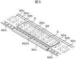
図5は供給テープ60の実施例と、その2つの供給テープ60を、連結テープ90を用いて人の手で連結した状態を示す。2つの供給テープ60は、例えば幅が8mm程度のエンボステープであり、大別して電子部品Dを収納する収納部60cを有するキャリアテープ60aと、電子部品Dが飛び出さないように収納部60cを覆うカバーテープ60bを具備し、さらにキャリアテープ60aにはカバーテープ60bによって覆われない長手方向の端部側に供給テープ60を移動させるためのスプロケット歯(図示せず)に係合するスプロケット孔60dを有する。一定のピッチを持ったスプロケット歯によって駆動されるために、スプロケット孔60dはスプロケット歯と同一のピッチを有する。2つの供給テープを連結したときも、2つの供給テープのスプロケット孔60dを同一ピッチで連結する必要がある。そのために、図5では、2つの供給テープの接続端を、前記条件を満足することが分かり易い、それぞれの半円形のスプロケット孔60dsの位置で供給テープの長手方向に直角に切断した面としている。なお、本実施形態のスプライシング冶具が扱うテープは、エンボステープに限らず、例えば紙テープを対象にすることができる。
FIG. 5 shows an embodiment of the
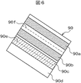
図6は長さが例えば40mm程度の連結テープ90の一例を示した図である。連結テープ90は粘着面を有し、同サイズの台紙(図示せず)に貼り付けられている。連結テープ90は、貼り付ける位置を明示する斜線で示す黒い部分と、その間に設けられた透明部分90dがある。90aは2つの供給テープ60のキャリアテープ60aの裏面同士を連結する裏面連結部を示す。90bは2つの供給テープ60のカバーテープ60bの表面同士を連結する表面連結部を示す。90cは2つの供給テープ60のキャリアテープ60aのスプロケット孔60dを有する側部同士を連結する側部連結部を示す。破線90e、90fは連結する際の折り目を示す。また、台紙には2つの供給テープ60を連結する際に貼り付ける位置をガイドするように分割して剥がれるようになっている。
FIG. 6 is a view showing an example of the connecting
まず、裏面連結部90a及び表面連結部90b上の第1の台紙を剥がし、残った台紙に沿って、2つの供給テープ60のカバーテープ60bを順次表面連結部90bに貼り付ける。次に、折り目90fから連結テープを折り、裏面連結部90aを2つの供給テープ60のキャリアテープ60aに貼り付ける。その後、側部連結部90c上の第2の台紙を剥がし、2つの供給テープ60のキャリアテープ側部に当たる折り目90eを折って側部連結部90cを貼り付けて連結を終了させる。このとき、スプロケット孔60dの部分の連結テープ90の透明部分90dで覆われるが、スプライシング終了後、再びスプロケット歯と係合するときは、連結テープ90の対応する部分をスプロケット歯が破るので装着処理に支障をきたすことはない。
First, the first mount on the back
作業員は、このような人手による作業を、例えば、部品切れが近い現供給テープが電子部品Dの取り出し口を有するフィーダ(図示せず)に繋がっており、また他方の新たな供給テープも収納されている供給リール(図示せず)に繋がった状態で行う。従って、この作業はある種の器用さが必要であり、接続したつもりでも剥がれてしまうことがあった。 For example, the worker can perform such manual work, for example, the current supply tape that is almost out of components is connected to a feeder (not shown) having an outlet for the electronic component D, and the other new supply tape is also stored. This is performed while connected to a supply reel (not shown). Therefore, this work requires some kind of dexterity, and even if it is intended to be connected, it may come off.
上記の説明した連結テープ90は一例であり、電子部品Dの寸法、供給テープ60の幅等によって、各連結部の幅並びに表面連結部及び裏面連結部の間または側部連結部及び表面連結部間の距離などは異なる。また、連結テープ自体も側部連結部がないなどの様々な形態がある。これから説明するスプライシング冶具はこのような様々な形態の連結テープに適用可能である。
The above-described connecting
次に本発明の実施形態の構成と動作を説明する。
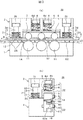
図1は本発明の第1の実施形態であるスプライシング冶具20を示す。図1(a)は、上述した連結した2つの供給テープ60を長手方向にして挿入するスプライシング冶具20の側面図を示す。図1(b)は図1(a)の矢印Aの方向から見た正面図を示す。
Next, the configuration and operation of the embodiment of the present invention will be described.
FIG. 1 shows a
スプライシング冶具20は、2つの供給テープ60の接続部12を確りと固定するために、開口部14から2つの供給テープ60を挿入し、回転可能な押圧部材であるローラ8で接続部12上を押圧し、ローラ8を回転させる。そのために、スプライシング冶具20は、大別して、構造的には、下側の下ベース1と上側の上ベース2を有し、機能的には、開口部14から挿入された2つの供給テープ60の接続部12を押圧部材で押圧し、確りと接続部12を固定する押圧手段22と、押圧部材を接続部に接触させる接触手段21とを有する。
The
まず、接触手段21から説明する。接触手段21は上ベース2に設けられ、図1(a)の側面両側に設けられた第1の摺動部を形成する円筒形の孔3dと、孔3dを摺動し上側に孔3dより径が大きい頭部3tを備え、下側が下ベース1に固定された柱状部材である円柱のピン3と、上側ベース2と下側ベース1との間のピン3の周囲に設けられた第1の弾性部材であるスプリング5とを有する。この構造によって、上側ベース2を押すと、上側ベース2はそのストッパ2sが下側ベース1に接触する位置まで移動することができる。また、スプリング5は常に下ベース1と上ベース2が離れる方向に力が働いている。これにより、上ベース2に外力を加えない限り、上ベース2が、下ベース1と離れた状態、即ち開いた状態になる。この結果、上ベース2を押すと、後述する押圧部材であるローラ8が2つの供給テープ60の接続部12に接触することができる。
First, the contact means 21 will be described. The contact means 21 is provided on the upper base 2 and has a
上記の例では、接触手段を上ベースに設けたが、同様な機構を下ベースに設けてもよい。また、柱状部材の形状としては円柱の他、円筒や多角柱などが適している。さらに、弾性部材としてはゴムなどの弾性を有する部材であってもよい。 In the above example, the contact means is provided on the upper base, but a similar mechanism may be provided on the lower base. Moreover, as the shape of the columnar member, a cylinder, a polygonal column, or the like is suitable in addition to a column. Further, the elastic member may be a member having elasticity such as rubber.
次に押圧手段22を説明する。押圧手段22は、上ベース2に設けられた上ベース押圧手段と下ベース部1に設けられた下ベース押圧手段とを有する。
上ベース押圧手段は、接続部12上を回転移動する複数の押圧部材であるローラ8と、接触手段21によって、ローラ8が接続部12に接触したときに、ローラ8を接続部12に押付ける第2の弾性部材であるスプリング6とを有する。ローラ8は、押圧部材支持部であるコの字状のプレート7に回転可能に設けられた回転軸9に固定されている。ローラ8は例えば導電性の樹脂又は金属でできており、帯電することを防止している。
Next, the pressing means 22 will be described. The pressing means 22 includes an upper base pressing means provided on the upper base 2 and a lower base pressing means provided on the
The upper base pressing means presses the
一方スプリング6は、接触手段21のスプリング5と同様に、第2の摺動部を形成する円筒形の孔4dと、孔4dを摺動し上側に孔4dより径が大きい頭部4tを備え、下側がプレート7に固定されたピン4の下部側周囲に設けられている。また、スプリング6は、摺動部材と押圧部材支持部とを常に離間する方向に力が作用している。
On the other hand, the
一方、下ベース押圧手段は、接続部12を回転可能の支持する回転部材であるローラ11と、ローラ11を固定し下ベース1に回転可能設けられた回転軸10を有する。ローラ11には、供給テープ60の収納部60sを収納するための凹部16を有する。この凹部16によって、収納部60sが潰れることなくスプライシングすることができる。図1(b)では、凹部16の底部と収納部60sとの間に隙間を設けているが、なくてもよい。
On the other hand, the lower base pressing means includes a
また、下ベース2のローラ11を有する右端には、図1(b)に破線で示したように上方へ突き出した供給テープガイド18を設けてもよい。供給テープガイド18を設けることによって、紙テープなど厚さの薄い供給テープ60を作業者は正規の位置にセットし易くなり、或いは且つ本冶具で処理作業中の供給テープ60の外れを防止することができる。
Further, a
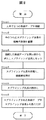
次に、本実施形態であるスプライシング冶具によるスプライシング方法を図1乃至図3を用いて説明する。図2は本発明の実施形態におけるスプライシングの処理フローを示した図である。図3(a)、図3(b)は、図1(a)、図1(b)に対応する図で、上部ベース2を押して開口部14を閉じて2つの供給テープ60の接続部12を押圧している状態を示す。
Next, the splicing method by the splicing jig which is this embodiment is demonstrated using FIG. 1 thru | or FIG. FIG. 2 is a diagram showing a processing flow of splicing in the embodiment of the present invention. 3 (a) and 3 (b) are views corresponding to FIGS. 1 (a) and 1 (b). The upper base 2 is pushed to close the
まず、作業員が手で連結テープ90を用い2つの供給テープ60を接続する(Step1)。次に、図1に示す状態で、一方の手の手のひらに接触手段21側を載せ(Step2)、他方の手で接続した2つの供給テープ60を開口部14から挿入し、供給テープ60の収納部60cが凹部16に収納されるようにスプライシング冶具20にセットする(Step3)。その後、一方の手でスプライシング冶具20を把持し、図3に示すように接触手段21を接続部12に接触させ押圧する(Step4)。このとき、上ベース2の下端面2A、即ちストッパ2sが下ベース1の上面1Aに当り、スプリングも所定量縮んだ状態でほぼ一定の力で安定して接続部12を押圧することができる。また、スプリング6が無い場合でも、ピン4を上ベース2に固定することで作業員の手で押圧できる。
First, the operator connects the two
次に、他方の手で接続した供給テープを例えば図3示す位置Eで保持し、スプライシング冶具20を矢印Bの方向に押出すと、中央のローラ8は接続部12の上を押圧しながら回転移動し、一方、ローラ11がキャリアテープ60aを支持しながら回転移動し、さらに、左側のローラ8は接続部12の上部を押圧しながら回転移動し、その結果、接続部を確りと固定することができる(Step5)。次に、一方の手を開放すると、接触手段21のスプリング5によって、上ベース2が下ベース1から離れ、図1に示すように開口部14が形成され、スプライシングされ確りと接続された2つの供給テープ60を取り出し(Step6)、スプライシング作業を終了させる。
Next, when the supply tape connected with the other hand is held at, for example, position E shown in FIG. 3 and the
以上説明した実施形態によれば、連結テープがカバーテープ60b及びキャリアテープ60aに確実に張り合わされ、剥がれを防止できるスプライシング冶具及びスプライシング方法を提供できる。上記説明では接続部12を中央のローラ8にセットしたが、接続部12が図3に破線で示したように左端のローラ11の左側に位置するように供給テープ60をスプライシング冶具にセットし、スプライシング冶具を矢印B方向に移動させると接続部12は中央及び左右の3箇所のローラで押圧されより一層確実に貼り合わせることができる。
また、以上説明した実施形態によれば、片手で操作可能なハンディ型であり、取り扱いが容易なスプライシング冶具を提供できる。
更に、以上説明した実施形態によれば、スプライシング冶具20は図1(a)に示すように、紙面左右において対象であり、右利きの人でも左利きの人でも同じように操作することが可能である。
According to the embodiment described above, it is possible to provide a splicing jig and a splicing method in which the connecting tape is securely bonded to the
Moreover, according to embodiment described above, the splicing jig which is a handy type which can be operated with one hand and is easy to handle can be provided.
Furthermore, according to the embodiment described above, the
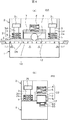
図4は本発明の第2の実施形態であるスプライシング冶具20Aを示し、図4(a)、図4(b)はそれぞれ第1の実施形態示す図3(a)、図3(b)に対応する図である。
第2の実施形態の第1の実施形態と異なる点は次の2点である。その他の点は第1の実施形態と基本的には同じである。
FIG. 4 shows a
The second embodiment is different from the first embodiment in the following two points. The other points are basically the same as those in the first embodiment.
異なる第1の点は、ローラ8が一つ設けられている点である。第1の実施形態では、ローラ8が複数あったので、スプライシング冶具20を矢印B方向へ移動させる場合には接続部12を右側のローラの右側の部分を除く適当な位置に挿入しても、必ず接続部12を押圧するローラ6が存在したが、第2の実施形態では、矢印Cのようにスプライシング冶具20Aを押出すとすれば、図4(a)ではローラ6より紙面左側に接続部12を開口部から挿入する。そのために、作業員の接続部12の挿入位置が明確になるように、右利き用或いは左利き用の挿入位置を示す位置合せマーク17を設けている。なお、本実施形態では、図4に示すように中央にローラ6を設けたが、両側にローラ6を設けてもよい。
A different first point is that one
第2の点は、下ベース1にはローラ11を設けていない点である。従って、スプライシング冶具20Aの矢印C方向の移動時には、キャリアテープ60bは下ベースに設けられた凹部16の両端側上部の摺動面を摺動する。
The second point is that the
第3の点は、図4に示す第2の実施形態では、スプリング6の上端及び下端がそれぞれ上ベース2及びプレート7に固定され、作業者が力を加えていないときには、スプリング6にプレート7が吊り下がり空間ができるようにしている。
The third point is that, in the second embodiment shown in FIG. 4, the upper end and the lower end of the
第2の実施形態においても、連結テープが確実に張り合わされ、剥がれを防止できるスプライシング冶具及びスプライシング方法を提供できる。
また、以上説明した第2の実施形態においても、片手で操作可能なハンディ型であり、取り扱いが容易なスプライシング冶具を提供できる。
更に、以上説明した第2の実施形態においても、スプライシング冶具20Aは図1(a)に示すように、紙面左右において対象であり、右利きの人でも左利きの人でも同じように操作することが可能である。
Also in the second embodiment, it is possible to provide a splicing jig and a splicing method in which the connecting tapes are securely attached and can be prevented from peeling off.
Also in the second embodiment described above, a splicing jig that is a handy type that can be operated with one hand and is easy to handle can be provided.
Furthermore, also in the second embodiment described above, the
以上第1及び第2の実施形態では押圧部材として回転可能な円柱状のローラを設けたが、接続部に摺動させる枕木のような半円柱状の摺動部をスプライシング冶具の移動方向に複数設け、該半円柱状上の摺動部がスプライシング冶具の移動と共に接続部上を摺動するようにしてもよい。 As described above, in the first and second embodiments, the rotatable cylindrical roller is provided as the pressing member, but a plurality of semi-cylindrical sliding portions such as sleepers to be slid on the connecting portion are provided in the moving direction of the splicing jig. The sliding part on the semi-cylindrical shape may be slid on the connecting part with the movement of the splicing jig.
以上本発明の実施態様について説明したが、上述の説明に基づいて当業者にとって種々の代替例、修正又は変形が可能であり、本発明はその趣旨を逸脱しない範囲で前述の種々の代替例、修正又は変形を包含するものである。 Although the embodiments of the present invention have been described above, various alternatives, modifications, and variations can be made by those skilled in the art based on the above description, and the present invention is not limited to the various alternatives described above without departing from the spirit of the present invention. It includes modifications or variations.
1:下ベース 2:上ベース
2s:ストッパ 3、4:ピン
3d、4d:孔 3t、4t:ピンの頭部
5、6:スプリング 7:コの字状のプレート
8、11:ローラ 9、10:回転軸
12:接続部 14:開口部
16:凹部 17:位置合せマーク
20:スプライシング冶具 21:接触手段
22:押圧手段 60:供給テープ
60a:キャリアテープ 60b:カバーテープ
60c:供給テープの収納部 60d:スプロケット孔
90:連結テープ 90a:裏面連結部
90b:表面連結部 90c:側部連結部
D:電子部品
1: Lower base 2:
60c:
Claims (14)
前記連結テープで接続された接続部を有する前記2つの供給テープを下から支持する下ベースと、前記接続面の上部を上から押圧する押圧部材を有する上ベースと、前記上ベースと下ベースを相対的に移動させ前記押圧部材を前記接続部に接触させる接触手段とを有することを特徴とするスプライシング冶具。 In a splicing jig for splicing a carrier tape having a storage part for storing electronic components and two supply tapes having a cover tape covering the storage part with a connecting tape,
A lower base for supporting the two supply tapes having a connecting portion connected by the connecting tape from below; an upper base having a pressing member for pressing an upper portion of the connection surface from above; and the upper base and the lower base. A splicing jig comprising contact means for moving the pressing member in contact with the connecting portion.
前記連結テープで接続された接続面を有する前記2つの供給テープを下から支持し、前記接続面の上部を上から押圧する前記押圧部材を前記接続部に接触させて前記接続部を固定することを特徴とするスプライシング方法。 In a splicing method in which a worker tapes a carrier tape having a storage part for storing electronic components and two supply tapes having a cover tape covering the storage part by connecting with a connecting tape,
The two supply tapes having a connection surface connected by the connecting tape are supported from below, and the pressing member that presses the upper portion of the connection surface from above is brought into contact with the connection portion to fix the connection portion. Splicing method characterized by the above.
Priority Applications (1)
| Application Number | Priority Date | Filing Date | Title |
|---|---|---|---|
| JP2011050523A JP2012190837A (en) | 2011-03-08 | 2011-03-08 | Splicing jig and splicing method |
Applications Claiming Priority (1)
| Application Number | Priority Date | Filing Date | Title |
|---|---|---|---|
| JP2011050523A JP2012190837A (en) | 2011-03-08 | 2011-03-08 | Splicing jig and splicing method |
Publications (1)
| Publication Number | Publication Date |
|---|---|
| JP2012190837A true JP2012190837A (en) | 2012-10-04 |
Family
ID=47083728
Family Applications (1)
| Application Number | Title | Priority Date | Filing Date |
|---|---|---|---|
| JP2011050523A Withdrawn JP2012190837A (en) | 2011-03-08 | 2011-03-08 | Splicing jig and splicing method |
Country Status (1)
| Country | Link |
|---|---|
| JP (1) | JP2012190837A (en) |
Cited By (5)
| Publication number | Priority date | Publication date | Assignee | Title |
|---|---|---|---|---|
| CN104114014A (en) * | 2013-04-22 | 2014-10-22 | 富士机械制造株式会社 | Clamp for belt connection |
| WO2015079488A1 (en) * | 2013-11-26 | 2015-06-04 | 富士機械製造株式会社 | Device for determining whether or not carrier tapes can be connected |
| JP2016001649A (en) * | 2014-06-11 | 2016-01-07 | 日東電工株式会社 | Carrier tape connection jig |
| JP2017064791A (en) * | 2015-10-02 | 2017-04-06 | Jfeスチール株式会社 | Continuous casting slab cutting device |
| CN112722391A (en) * | 2020-12-08 | 2021-04-30 | 深圳市宝尔威精密机械有限公司 | Copper buckle connects material machine |
-
2011
- 2011-03-08 JP JP2011050523A patent/JP2012190837A/en not_active Withdrawn
Cited By (7)
| Publication number | Priority date | Publication date | Assignee | Title |
|---|---|---|---|---|
| CN104114014A (en) * | 2013-04-22 | 2014-10-22 | 富士机械制造株式会社 | Clamp for belt connection |
| JP2014212280A (en) * | 2013-04-22 | 2014-11-13 | 富士機械製造株式会社 | Jig for tape connection |
| WO2015079488A1 (en) * | 2013-11-26 | 2015-06-04 | 富士機械製造株式会社 | Device for determining whether or not carrier tapes can be connected |
| JPWO2015079488A1 (en) * | 2013-11-26 | 2017-03-16 | 富士機械製造株式会社 | Device for determining whether or not carrier tape can be connected |
| JP2016001649A (en) * | 2014-06-11 | 2016-01-07 | 日東電工株式会社 | Carrier tape connection jig |
| JP2017064791A (en) * | 2015-10-02 | 2017-04-06 | Jfeスチール株式会社 | Continuous casting slab cutting device |
| CN112722391A (en) * | 2020-12-08 | 2021-04-30 | 深圳市宝尔威精密机械有限公司 | Copper buckle connects material machine |
Similar Documents
| Publication | Publication Date | Title |
|---|---|---|
| JP2012190837A (en) | Splicing jig and splicing method | |
| JP6427003B2 (en) | Electronic component supply apparatus, reel device, and component storage tape replenishment method | |
| CN105993211A (en) | Tape feeder | |
| CN102305228A (en) | Automatic adhering device of transparent adhesive tape | |
| KR20130110062A (en) | Carrier tape connecting apparatus | |
| JP2011233600A (en) | Jig and attachment method | |
| JP2014086504A (en) | Top tape peel-off device and peel-off method | |
| CN100434344C (en) | Connection method and connection structure of parts supply belt, and scissors for parts supply belt | |
| JP6320001B2 (en) | Tape tip processing jig | |
| CN110625218A (en) | An automatic wire welding machine for earphone plugs and its working method | |
| JP6250877B2 (en) | Tape connection jig | |
| US5170612A (en) | Packing apparatus | |
| CN103786912A (en) | Carrier tape connecting method and carrier tape connecting member | |
| JP4328374B2 (en) | Clip ribbon and connecting device for connecting electronic component carrier tape for surface mounting | |
| JP2005212029A (en) | Storage tape cutting device and cutting method thereof | |
| JPH06100217A (en) | Connecting device for taping electronic components | |
| CN204777931U (en) | Sticky tape cutterbar that sticky tape of plugging into was used | |
| JP2012169352A (en) | Jig, and connection method of tape | |
| KR101747222B1 (en) | An apparatus for handling end portion of tape | |
| IT201900012204A1 (en) | DEVICE FOR THE APPLICATION OF A PROTECTIVE FILM ON THE SCREEN OF AN ELECTRONIC DEVICE | |
| JP2010087390A (en) | Device for splicing component supply tape | |
| JP2004161420A (en) | Tape connection tool | |
| JP2009113980A (en) | Device for forming folding of adhesive tape | |
| CN2845419Y (en) | Splicing fixtures used in the production process of surface mount technology | |
| CN200976728Y (en) | Tape supply device and turntable of PC board automatic tape sticking machine |
Legal Events
| Date | Code | Title | Description |
|---|---|---|---|
| A300 | Withdrawal of application because of no request for examination |
Free format text: JAPANESE INTERMEDIATE CODE: A300 Effective date: 20140513 |