JP2012190844A - Method for multiple stage of solar cell module - Google Patents
Method for multiple stage of solar cell module Download PDFInfo
- Publication number
- JP2012190844A JP2012190844A JP2011050646A JP2011050646A JP2012190844A JP 2012190844 A JP2012190844 A JP 2012190844A JP 2011050646 A JP2011050646 A JP 2011050646A JP 2011050646 A JP2011050646 A JP 2011050646A JP 2012190844 A JP2012190844 A JP 2012190844A
- Authority
- JP
- Japan
- Prior art keywords
- solar cell
- cell module
- holding
- holding member
- cell modules
- Prior art date
- Legal status (The legal status is an assumption and is not a legal conclusion. Google has not performed a legal analysis and makes no representation as to the accuracy of the status listed.)
- Withdrawn
Links
Images













Classifications
-
- Y—GENERAL TAGGING OF NEW TECHNOLOGICAL DEVELOPMENTS; GENERAL TAGGING OF CROSS-SECTIONAL TECHNOLOGIES SPANNING OVER SEVERAL SECTIONS OF THE IPC; TECHNICAL SUBJECTS COVERED BY FORMER USPC CROSS-REFERENCE ART COLLECTIONS [XRACs] AND DIGESTS
- Y02—TECHNOLOGIES OR APPLICATIONS FOR MITIGATION OR ADAPTATION AGAINST CLIMATE CHANGE
- Y02E—REDUCTION OF GREENHOUSE GAS [GHG] EMISSIONS, RELATED TO ENERGY GENERATION, TRANSMISSION OR DISTRIBUTION
- Y02E10/00—Energy generation through renewable energy sources
- Y02E10/50—Photovoltaic [PV] energy
Landscapes
- Packaging Frangible Articles (AREA)
- Photovoltaic Devices (AREA)
Abstract
【課題】太陽電池モジュールの多段積載及び梱包の自動化を可能とする。
【解決手段】保持部材1を上下方向に所定数嵌合して長尺状の保持体1Aを作製する第1工程と、作製した2つの保持体1Aを太陽電池モジュールの幅方向の幅に合わせて立設配置する第2工程と、立設配置された2つの保持体1Aの横方向に対向する2つの保持部12に、太陽電池モジュール80の長手方向の一方の両コーナー部81をそれぞれ嵌め合わせて太陽電池モジュール80を水平状態で仮保持する第3工程と、前記第3工程を、立設配置された2つの保持体1Aの横方向に対向する2つの保持部12の最下段から最上段まで所定回数繰り返す第4工程と、第4工程終了後、水平状態で仮保持された所定数の太陽電池モジュール80の長手方向の他方の両コーナー部81に、別に作製した2つの保持体の対向す保持部をそれぞれ嵌め合わせて立設配置する第5工程と、を実施する。
【選択図】図3CIt is possible to automate multistage loading and packing of solar cell modules.
A first step of producing a long holding body 1A by fitting a predetermined number of holding members 1 in the vertical direction, and adjusting the two produced holding bodies 1A to the width in the width direction of the solar cell module. The two corners 81 in the longitudinal direction of the solar cell module 80 are respectively fitted to the second step of standing up and arranging and the two holding portions 12 facing the lateral direction of the two holding bodies 1A arranged upright. In addition, the third step of temporarily holding the solar cell module 80 in a horizontal state and the third step are performed from the lowest stage of the two holding portions 12 facing the lateral direction of the two holding bodies 1A arranged upright. After the fourth step is repeated a predetermined number of times up to the upper stage, and after the completion of the fourth step, the two corners 81 in the longitudinal direction of the predetermined number of solar cell modules 80 temporarily held in a horizontal state are separately provided Fit the holding parts facing each other A fifth step of vertically arranged to fit, to implement.
[Selection] Figure 3C
Description
本発明は、搬送等のために太陽電池モジュールを多段に積載する方法に係り、より詳細には、太陽電池モジュールを平積みして多段に積載する際の積載作業の自動化に適した太陽電池モジュールの多段積載方法に関する。 The present invention relates to a method of stacking solar cell modules in multiple stages for transportation or the like, and more specifically, a solar cell module suitable for automating stacking operations when stacking solar cell modules in a multi-stage manner. It relates to a multi-stage loading method.
従来、水平に積み重ねられる光起電力モジュール(以下、太陽電池モジュールという。)を、輸送の際確実に保管するモジュール方式の差込みシステムが知られている(特許文献1参照)。 2. Description of the Related Art Conventionally, a modular plug-in system that securely stores photovoltaic modules (hereinafter referred to as solar cell modules) stacked horizontally is known (see Patent Document 1).
この差込みシステムでは、図11に示す成形品部材110を用いて、太陽電池モジュールを水平に積み重ねて梱包するようになっている。
In this insertion system, solar cell modules are horizontally stacked and packaged using a molded
簡単に説明すると、図11に示す成形品部材110は、円筒状に形成された支柱部111と、この支柱部111の周側壁から水平に延設された太陽電池モジュールのコーナー部を横から嵌め込んで挟持するための横方向に開口した挟持部112とを備え、支柱部111の上端面と下端面とには、上下に隣接配置される別の成形品部材111と順次嵌合するための、嵌合凹部113と嵌合凸部114とが設けられている。
Briefly, the
この成形品部材110を用いて太陽電池モジュールを水平に積み重ねる場合、まず、太陽電池モジュールの各コーナー部に、それぞれ成形品部材110の挟持部112を嵌め込み、この状態で1段目の太陽電池モジュールをパレット上に載置する。次に、同様にして、2段目の太陽電池モジュールの各コーナー部に、それぞれ成形品部材110の挟持部112を嵌め込み、この状態で、パレット上に載置した1段目の太陽電池モジュールのコーナー部に嵌め込んだ成形品部材110と、2段目の太陽電池モジュールのコーナー部に嵌め込んだ成形品部材110とを上下に対峙させ、下側の成形品部材110の嵌合凹部113に上側の成形品部材110の嵌合凸部114を嵌合して、2段目の太陽電池モジュールを積み重ねる。このような手順を所定段数繰り返して、太陽電池モジュールを水平に積み重ねていくようになっている。
When the solar cell modules are stacked horizontally using the
このような成形品部材110を用いた差込みシステムにおいて、特許文献1では、図11に示す成形品部材110は、枠部材を有しないフレームレス構造の太陽電池モジュールに好適に用いられている。
In such an insertion system using the
ところで、フレームレス構造の太陽電池モジュールは、2枚の合わせガラス構造となっているが、太陽電池モジュールは元々建材用であるため、液晶用のガラスとは異なり、切断後のガラスには多少の寸法誤差がある。例えば、縦1400mm、横1000mmの大型の太陽電池モジュールの場合、切断されたガラスには、元々、±1mm程度の寸法誤差がある。また、コーナー部の直角度においても、90°±0.0025°〜0.0020°程度の誤差がある。 By the way, the solar cell module of the frameless structure has a laminated glass structure of two sheets. However, since the solar cell module is originally for building materials, unlike the glass for liquid crystal, the glass after cutting has some There is a dimensional error. For example, in the case of a large solar cell module having a length of 1400 mm and a width of 1000 mm, the cut glass originally has a dimensional error of about ± 1 mm. In addition, there is an error of about 90 ° ± 0.0025 ° to 0.0020 ° in the squareness of the corner portion.
このような誤差に加え、フレームレス構造の太陽電池モジュールを作製する際、太陽電池基板(太陽電池ストリング)を2枚のガラスで挟み合わせるときに若干ずれる場合もあり、このようなずれによる誤差も考慮すると、作製された各太陽電池モジュールの寸法誤差は最大で2〜3mm程度となる。 In addition to such errors, when manufacturing a solar cell module with a frameless structure, there is a case where the solar cell substrate (solar cell string) is slightly displaced when sandwiched between two pieces of glass. Considering this, the dimensional error of each produced solar cell module is about 2 to 3 mm at the maximum.
しかし、図11に示す成形品部材110を用いて太陽電池モジュールを積み重ねていく場合、太陽電池モジュールのコーナー部の4箇所の成形品部材110を同時に嵌合していく必要があるが、上記したように各太陽電池モジュール自体に寸法誤差があるため、上下に対峙する成形品部材110同士も横方向に若干ずれた状態となる。そのため、この成形品部材110同士の嵌合を機械により自動化しようとしても、各成形品部材110の嵌合位置調整を精度良く行う必要があるため、実質的に機械による自動化が難しいといった問題があった。そのため、従来は、このような太陽電池モジュールの積み重ね作業を作業者による手作業で行う必要があった。
However, when stacking solar cell modules using the
一方、図11に示す成形品部材110を用いて太陽電池モジュールの積み重ねを自動化するためには、太陽電池モジュールの寸法誤差分を、上下に対峙する成形品部材110の嵌合凹部113と嵌合凸部114との嵌合構造で吸収する必要がある。すなわち、上下に対峙する成形品部材110の嵌合凹部113と嵌合凸部114との嵌合構造に、少なくとも太陽電池モジュールの寸法誤差分(2〜3mm)の遊びを持たせる必要がある。そのため、積み重ねられた太陽電池モジュール同士が水平方向にずれ易い(すなわち、がたつきのある)構造となり、搬送時等の振動に対して弱い積み重ね構造になるといった問題があった。
On the other hand, in order to automate the stacking of the solar cell modules using the
本発明はかかる問題点を解決すべく創案されたもので、その目的は、搬送等のために太陽電池モジュールを多段に積載する方法に係り、より詳細には、多段積載の自動化に適した太陽電池モジュールの多段積載方法を提供することにある。 The present invention was devised to solve such problems, and its purpose relates to a method of stacking solar cell modules in multiple stages for transportation or the like. More specifically, the present invention is suitable for automation of multi-stage stacking. The object is to provide a multistage loading method of battery modules.
上記課題を解決するため、本発明に係る太陽電池モジュールの多段積載方法は、矩形状の太陽電池モジュールの一方向に対向する両端部をそれぞれ保持する保持部材を用いて前記太陽電池モジュールを多段に積み重ねて梱包する方法であって、前記保持部材は、前記太陽電池モジュールの端部を嵌め合わせて保持する保持部と、上下に隣接する他の保持部材と上下方向に嵌合する嵌合部とを備えており、前記保持部材を上下方向に所定数嵌合することにより、上下方向に一定の間隔を存して所定数の前記保持部が形成された長尺状の保持体を作製する第1工程と、作製した2つの保持体を前記太陽電池モジュールの第1の方向(幅方向)の幅に合わせて立設配置する第2工程と、立設配置された前記2つの保持体の横方向に対向する2つの保持部に、太陽電池モジュールの前記第1の方向に直交する第2の方向(長手方向)の一方寄りの両端部をそれぞれ嵌め合わせて前記太陽電池モジュールを水平状態で仮保持する第3工程と、前記第3工程を、立設配置された前記2つの保持体の横方向に対向する2つの保持部の最下段から最上段まで、または最上段から最下段まで所定回数繰り返す第4工程と、前記第4工程終了後、水平状態で仮保持された前記所定数の太陽電池モジュールの前記第2の方向の他方寄りの両端部に、別に作製した2つの保持体の対向す保持部をそれぞれ嵌め合わせて前記2つの保持体を立設配置する第5工程と、を含むことを特徴としている。また、前記第3工程では、前記2つの保持体とは別に仮保持部材を用いて前記太陽電池モジュールを水平状態で仮保持する構成としている。 In order to solve the above-described problems, a multi-stage stacking method for solar cell modules according to the present invention is a multi-stage stacking method using a holding member that holds both ends of a rectangular solar cell module facing each other in one direction. In the method of stacking and packing, the holding member includes a holding unit that fits and holds the end of the solar cell module, and a fitting unit that fits in the vertical direction with other holding members that are vertically adjacent to each other. A long holding body in which a predetermined number of the holding portions are formed at a certain interval in the vertical direction by fitting a predetermined number of the holding members in the vertical direction. 1 process, the 2nd process of standingly arranging the produced two holding bodies according to the width in the first direction (width direction) of the solar cell module, and the side of the two holding bodies arranged upright Two holdings facing each other A third step of temporarily holding the solar cell module in a horizontal state by fitting both ends of the second direction (longitudinal direction) perpendicular to the first direction of the solar cell module to the respective portions, A fourth step in which the third step is repeated a predetermined number of times from the lowermost stage to the uppermost stage or from the uppermost stage to the lowermost stage of the two holding parts opposed in the lateral direction of the two holding bodies arranged upright; After completion of the fourth step, the opposing holding parts of two separately produced holding bodies are respectively fitted to both ends of the predetermined number of solar cell modules temporarily held in the horizontal state near the other side in the second direction. And a fifth step of arranging and arranging the two holding bodies upright. In the third step, the solar cell module is temporarily held in a horizontal state using a temporary holding member separately from the two holding bodies.
このような特徴を有する本発明によれば、所定数の太陽電池モジュールを多段に積載するに際して、保持部材を所定数嵌合した2つの長尺状の保持体をまず立設配置し、この2つの保持体の対向する保持部間に太陽電池モジュールの長手方向の一方寄りの両端部をそれぞれ横方向から差し込むようにして嵌め合わせていくことで、別途仮保持部材も加えて太陽電池モジュールを水平に保持した状態で、多段に積載するようにしている。そして、このように多段に積載後、太陽電池モジュールの長手方向の他方寄りの両端部に、別の2つの保持体の対向する保持部を横方向からそれぞれ嵌め合わせて、この2つの保持体を立設配置することにより、最終的に4つの保持体で太陽電池モジュールを保持して、太陽電池モジュールの多段積載を完了する。仮保持部材は、最終的に4つの保持体で太陽電池モジュールを保持した後は除去される。 According to the present invention having such a feature, when a predetermined number of solar cell modules are stacked in multiple stages, first, two long holding bodies fitted with a predetermined number of holding members are first placed upright. The solar cell module is horizontally leveled by adding a temporary holding member separately by inserting both ends of the solar cell module in the longitudinal direction between the two holding units facing each other so as to be inserted from the lateral direction. In this state, it is loaded in multiple stages. Then, after stacking in multiple stages in this way, the opposing holding parts of the other two holding bodies are fitted from both sides to the opposite ends of the solar cell module in the longitudinal direction, respectively. By arranging upright, the solar cell module is finally held by the four holding bodies, and the multi-stage stacking of the solar cell modules is completed. The temporary holding member is finally removed after the solar cell module is held by the four holding bodies.
すなわち、本発明の多段積載方法では、最初に位置固定するのは2つの保持体のみであり、残り2つの保持体は、多段に積載した太陽電池モジュールの端部に、保持部を単に嵌め合わせることによって、最終的な位置決めが行われることになる。 That is, in the multi-stage stacking method of the present invention, only two holding bodies are fixed in position first, and the remaining two holding bodies are simply fitted into the end portions of the solar cell modules stacked in multiple stages. As a result, final positioning is performed.
フレームレス構造の太陽電池モジュールは、上記背景技術で説明したように、作製された太陽電池モジュールの寸法誤差が最大で2〜3mm程度となる。 As described in the background art, the dimensional error of the manufactured solar cell module is about 2 to 3 mm at the maximum in the frameless structure solar cell module.
しかし、本発明の多段積載方法では、このような太陽電池モジュールの寸法誤差に影響されることなく、各保持体を太陽電池モジュールの端部に嵌合することができるため、太陽電池モジュールを多段積載する際の自動化が容易となる。 However, in the multi-stage stacking method of the present invention, each holding body can be fitted to the end portion of the solar cell module without being affected by the dimensional error of the solar cell module. Automation when loading is facilitated.
また、本発明に係る太陽電池モジュールの多段積載方法では、前記太陽電池モジュールの一方向に対向する両端部が、前記太陽電池モジュールの一方向に対向する両コーナー部であってもよい。 Moreover, in the multistage stacking method for solar cell modules according to the present invention, both end portions facing in one direction of the solar cell module may be both corner portions facing in one direction of the solar cell module.
このような構成によれば、太陽電池モジュールのコーナー部を保持部材で保持することから、水平方向へのずれ(すなわち、横ずれ)がなく、太陽電池モジュールを安定して多段に積載することができる。 According to such a configuration, since the corner portion of the solar cell module is held by the holding member, there is no horizontal displacement (that is, lateral displacement), and the solar cell modules can be stably stacked in multiple stages. .
また、本発明に係る太陽電池モジュールの多段積載方法では、前記保持部は、前記太陽電池モジュールの端部を挟み込むように断面コ字状に形成された構成としている。 Moreover, in the multistage stacking method of the solar cell modules according to the present invention, the holding portion is configured to have a U-shaped cross section so as to sandwich the end portion of the solar cell module.
このような構成によれば、太陽電池モジュールの端部を保持部材の保持部に嵌め合わせることで、上下方向のがたつきを防止することができる。これにより、搬送時の振動に対して、太陽電池モジュールの縦揺れを防止することができる。 According to such a configuration, rattling in the vertical direction can be prevented by fitting the end portion of the solar cell module to the holding portion of the holding member. Thereby, the vertical oscillation of the solar cell module can be prevented with respect to the vibration at the time of conveyance.
また、本発明に係る太陽電池モジュールの多段積載方法では、前記保持部は、前記太陽電池モジュールの端部を下から受け止めるように縦断面L字状に形成された構成としてもよい。 Moreover, in the multistage stacking method of the solar cell modules according to the present invention, the holding portion may be configured to have an L-shaped vertical cross section so as to receive an end portion of the solar cell module from below.
このような構成によれば、太陽電池モジュールの端部を保持部材の保持部上に、単に載置するだけでよいので、高さ方向の位置合わせを正確に行わなくても、太陽電池モジュールの端部を保持部に載置することができる。これにより、太陽電池モジュールの多段積載作業及びその後の梱包作業の自動化が容易となる。 According to such a configuration, since the end of the solar cell module only needs to be placed on the holding portion of the holding member, the solar cell module is not required to be accurately aligned in the height direction. The end portion can be placed on the holding portion. Thereby, automation of the multistage loading operation | work of a solar cell module and subsequent packing operation | work becomes easy.
また、本発明に係る太陽電池モジュールの多段積載方法では、前記第5工程終了後に、多段に積載された前記太陽電池モジュールの間に緩衝部材を挿入する工程が含まれた構成としてもよい。 Moreover, the multistage stacking method for solar cell modules according to the present invention may include a step of inserting a buffer member between the solar cell modules stacked in multiple stages after the fifth step.
保持部材のL字状の保持部に太陽電池モジュールの端部を単に載置しただけでは、上下方向へのがたつきを防止することができないが、多段に積載された太陽電池モジュールの間に緩衝部材を挿入することで、搬送時の振動等に対する太陽電池モジュールの縦揺れを防止することができる。 It is not possible to prevent rattling in the vertical direction by simply placing the end of the solar cell module on the L-shaped holding part of the holding member, but between the solar cell modules stacked in multiple stages. By inserting the buffer member, it is possible to prevent the solar cell module from swinging due to vibrations or the like during conveyance.
また、本発明に係る太陽電池モジュールの多段積載方法は、前記太陽電池モジュールがフレームレス構造の太陽電池モジュールに好適に利用される。本発明の多段積載方法を、太陽電池モジュールの周囲にアルミ製の枠部材を有しないフレームレス構造の太陽電池モジュールの多段積載方法に適用することで、太陽電池モジュールのガラスの破損を防止しつつ、効率よく多段積載作業及びその後の梱包作業を行うことができる。 Moreover, the multistage loading method of the solar cell module according to the present invention is preferably used for a solar cell module having a frameless structure. By applying the multi-stage stacking method of the present invention to a multi-stage stacking method for a solar cell module having a frameless structure that does not have an aluminum frame member around the solar cell module, the glass of the solar cell module is prevented from being damaged. Thus, it is possible to efficiently perform multi-stage loading work and subsequent packing work.
本発明に係る太陽電池モジュールの多段積載方法によれば、最初に位置固定するのは2つの保持体のみであり、残り2つの保持体については、多段に積載した太陽電池モジュールの端部に、保持部を単に嵌め合わせることによって、最終的な位置決めが行われるため、太陽電池モジュールの寸法誤差に影響されることなく、各保持体を太陽電池モジュールの端部に嵌合することができる。そのため、太陽電池モジュールの多段積載作業の自動化が容易に可能となる。 According to the multi-stage stacking method of solar cell modules according to the present invention, only the two holding bodies are fixed in position first, and the remaining two holding bodies are arranged at the end of the multi-stage solar cell modules, Since the final positioning is performed by simply fitting the holding portions, each holding body can be fitted to the end portion of the solar cell module without being affected by the dimensional error of the solar cell module. For this reason, it is possible to easily automate the multistage loading operation of the solar cell modules.
以下、本発明の実施の形態について、図面を参照して説明する。 Embodiments of the present invention will be described below with reference to the drawings.
<実施形態1>
実施形態1に係る太陽電池モジュールの多段積載方法は、矩形状の太陽電池モジュールの各コーナー部をそれぞれ保持する保持部材を用いて、太陽電池モジュールを多段に積み重ねる方法であり、特に、フレームレス構造の太陽電池モジュールの多段積載方法に好適に用いられる。
<
The multi-stage stacking method of solar cell modules according to
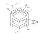
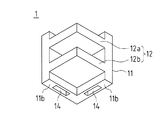
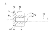
図1Aないし図1Cは、実施形態1に係る太陽電池モジュールの多段積載方法に用いられる保持部材の構成を示しており、図1Aは斜め上方からみた斜視図、図1Bは斜め下方からみた斜視図、図1Cは、図1AのI−I線断面図である。
1A to 1C show the structure of a holding member used in the multistage stacking method for solar cell modules according to
保持部材1は、太陽電池モジュール80のコーナー部81を横から嵌め合わせて保持する構造であり、平面視L字状に屈曲形成された基体部11と、この基体部11の内側壁面から該壁面に直交する方向に延設された挟持部(保持部)12とを備えている。
The holding
挟持部12は、平行に配置された上側挟持片12aと下側挟持片12bとで構成され、図1Cに示すように、太陽電池モジュール80のコーナー部81を挟み込むように横向きに開口した縦断面コ字状に形成されている。
The clamping
また、基体部11の上端面11a及び下端面11bには、上下に隣接配置される別の保持部材1と順次嵌合するための嵌合凸部13及び嵌合凹部14がそれぞれ設けられている。実施形態1では、嵌合凸部13は、基体部11の各片の上端面11aに1個ずつ、計2個設けられており、嵌合凹部14は、基体部11の各片の下端面11bに1個ずつ、計2個設けられている。ただし、嵌合凸部13及び嵌合凹部14の形成数はこれに限定されるものではなく、例えば基板部11の各辺の上端面11a及び下端面11bにそれぞれ2個ずつ、計8個設けられていてもよい。このような形状の保持部材1は、例えばPP(ポリプロピレン)やABS(アクリロニトリル・ブタジエン・スチレン共重合体)等の樹脂による射出成形によって形成されている。
Further, the
実施形態1では、このような形状の保持部材1を用いてフレームレス構造の太陽電池モジュールを水平に積み重ねて梱包する。
In
また、実施形態1の多段積載方法では、図2に示すような仮保持部材2を用いる。仮保持部材2は、太陽電池モジュール80を積載後、梱包前に取り除かれる部材である。
In the multistage loading method of the first embodiment, a
仮保持部材2は、矩形状の支持基板21に立設された支柱22の一側面に、上下方向に一定の間隔T1を存して同方向に水平に延設された多数の腕杆23を備えている。ここで、一定の間隔T1は、保持部材1を上下に積み重ねるように嵌合したとき、隣接する挟持部材12同士の間隔(具体的には、下側挟持片12b同士の間隔)と同じ間隔である。
The
なお、図示は省略しているが、支持基板21に車輪を取り付けておくことで、仮保持部材2のスムーズな移動が可能となるようにしておいてもよい。
Although not shown, the
次に、上記各部材1,2を用いた実施形態1の多段積載方法について、図3Aないし図3Hに示す各工程図を参照して説明する。
Next, the multi-stage stacking method of the first embodiment using the
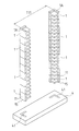
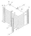
第1工程では、図3Aに示すように、多数用意した保持部材1を上下方向に所定数嵌合することにより、上下方向に一定の間隔を存して所定数の挟持部12が形成された長尺状の保持体1Aを作製する。ここで、実施形態1では、太陽電池モジュール80を例えば水平に10段積み重ねて一体梱包するものとすると、1つの保持体1Aは、10個の保持部材1を上下一体に、かつ、着脱可能に嵌め合わせた構造となる。
In the first step, as shown in FIG. 3A, a predetermined number of holding
第2工程では、図3Bに示すように、このように作製した2つの保持体1Aを、太陽電池モジュール80の幅方向(第1の方向)の幅T11に合わせて立設配置する。ここで、保持体1Aを立設させる手法としては、実施形態1では、図3Bに示すように、板状の立設基板4を用意し、この立設基板4に、保持体1Aの下端部(すなわち、最下段の保持部材1の基体部11の下端部15)が着脱可能に嵌まり込むように、L字状に形成された一対の貫通穴41,41を設けておく。そして、この貫通穴41,41に各保持体1Aの下端部15を嵌め合わせることで、各保持体1Aを立設配置する構成としている。ただし、立設配置の手法はこのような構成に限定されるものではなく、例えば立設基板4の代わりに滑りにくいゴム状の基材を床に敷設し、ここに2つの保持体1Aを幅T11の間隔で立設配置し、上部を図示しない支持杆のようなもので横方向から支持するようにしてもよい。
In the second step, as shown in FIG. 3B, the two holding
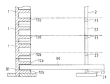
第3工程では、図3C及び図3Dに示すように、立設配置された2つの保持体1Aの各挟持部12に、太陽電池モジュール80の幅方向に直交する長手方向(第2の方向)の一方の両コーナー部(図3C中、左側の両コーナー部)81をそれぞれ横方向(図3C中、X方向)から嵌め合わせ、この嵌め合わせた状態で、2つの仮保持部材2を用いて太陽電池モジュール80の長手方向の中程(より具体的には、図3C中、右側のコーナー部81に近い箇所)を幅方向の両側から(図3C中、Y1方向から)挟み込むように仮保持して、太陽電池モジュール80を水平状態に保持する。
In the third step, as shown in FIG. 3C and FIG. 3D, the longitudinal direction (second direction) perpendicular to the width direction of the
図3C及び図3Dでは、太陽電池モジュール80を保持体1Aの最下段から順次嵌め合わせる構成としているため、図3Dに示すように、下から1段目の太陽電池モジュール80は、保持体1Aの下から1段目の保持部材1の下側挟持片12bと仮保持部材2の下から1段目の腕杆23とによって支持されることになる。因みに、図3Dに示すように、保持体1Aと仮保持部材2とを立設した状態で、各段の保持部材1の下側挟持片12bと仮保持部材2の各段の腕杆23とは、同じ高さとなるように設けられている。
3C and 3D, since the
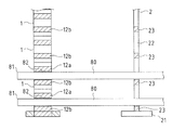
次に、図3E及び図3Fに示すように、仮保持部材2の下から2段目の腕杆23上を通して、2つの保持体1Aの下から2段目の保持部材1の挟持部12に、2段目の太陽電池モジュール80の長手方向の一方の両コーナー部81をそれぞれ横方向(図3E中、X方向)から嵌め合わせる。これにより、図3Fに示すように、保持体1Aの下から2段目の保持部材1の下側挟持片12bと仮保持部材2の下から2段目の腕杆23とによって、下から2段目の太陽電池モジュール80が支持されることになる。
Next, as shown in FIG. 3E and FIG. 3F, it passes from above the
この第3工程を10回繰り返すこと(第4工程を実施すること)により、立設配置された2つの保持体1Aと2つの仮保持部材2とによって、10個の太陽電池モジュール80が水平状態で多段に積載される。
By repeating the third step 10 times (performing the fourth step), the ten
第5工程では、図3Gに示すように、水平状態で仮保持された10個の太陽電池モジュール80の長手方向の他方の両コーナー部(図3G中、右側の両コーナー部)81に、別に作製した2つの保持体1Aの挟持部12をそれぞれ横方向(図3G中、X方向)から嵌め合わせて、2つの保持体1Aを立設配置する。これにより、図3Hに示すように、10個の太陽電池モジュール80は、4本の保持体1Aによって4隅のコーナー部81が保持されることになる。この後、対向している2つの仮保持部材2を幅方向(図3H中、Y2方向)に広げるように移動させることで、仮保持部材2の腕杆23を太陽電池モジュール80の間から引き抜く。
In the fifth step, as shown in FIG. 3G, in the other corners in the longitudinal direction of the ten
以上により、10個の太陽電池モジュール80が水平状態で積み重ねられたので、この後は、図示しない梱包工程を実施して、4つの保持体1Aに保持された10個の太陽電池モジュール80を一体に梱包する。梱包方法としは、従来周知の方法で行えばよいが、例えば、太陽電池モジュール80の周囲を4つの保持体1Aも含めて段ボール等で被覆し、樹脂バンドで結束することによって一体に梱包することができる。
As described above, since the ten
なお、このような梱包に際しては、立設基板4も除去される。すなわち、立設基板4は、最初の2つの保持体1Aを立設させるためのものであり、4本の保持体1Aで10個の太陽電池モジュール80を支持した後は、不要である。すなわち、立設基板4も仮保持部材2と同様、新たな梱包を行うたびに再利用されるリユース部材である。
Note that the standing
以上説明したように、実施形態1の多段積載方法では、最初に位置固定するのは2つの保持体1Aのみであり、残り2つの保持体1Aは、多段に積載した太陽電池モジュール80の残り2つのコーナー部81に、挟持部12をそれぞれ単に嵌め合わせることによって、最終的な位置決めが行われることになる。すなわち、太陽電池モジュール80の寸法誤差に影響されることなく、各保持体1Aを太陽電池モジュール80の各コーナー部81に嵌合することができるため、機械による自動梱包化が容易となる。
As described above, in the multi-stage stacking method of the first embodiment, only the two holding
また、太陽電池モジュール80のコーナー部81の2辺をL字状の保持部材1で保持することから、水平方向へのずれ(すなわち、横ずれ)がなく、太陽電池モジュール80を安定して多段に積載することができる。
Further, since the two sides of the
さらに、太陽電池モジュール80のコーナー部81を保持部材1の挟持部12に嵌め合わせることで、上下方向のがたつきも防止することができる。すなわち、搬送時の振動に対して、太陽電池モジュール80の縦揺れを防止することができる。
Further, by fitting the
さらにまた、実施形態1の多段積載方法では、フレームレス構造の太陽電池モジュールの梱包作業を、太陽電池モジュールのガラス端部の破損を防止しつつ、効率よく行うことができる。 Furthermore, in the multi-stage stacking method according to the first embodiment, the packing operation of the solar cell module having the frameless structure can be efficiently performed while preventing the glass end portion of the solar cell module from being damaged.
なお、実施形態1では、太陽電池モジュール80を多段に積載していく第3工程の繰り返し(すなわ、第4工程)を、最下段から始めて最上段まで実施する構成としているが、これとは逆に、最上段から始めて最下段まで実施する構成としてもよい。
In the first embodiment, the third step of stacking the
<実施形態2>
実施形態2の多段積載方法も、実施形態1の多段積載方法と基本的に同じであるが、使用する保持部材1の形状が異なっている。
<
The multistage loading method of the second embodiment is basically the same as the multistage loading method of the first embodiment, but the shape of the holding
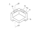
図4A〜図4Cは、実施形態2に係る太陽電池モジュールの多段積載方法に用いられる保持部材の構成を示しており、図4Aは斜め上方からみた斜視図、図4Bは斜め下方からみた斜視図、図4Cは、図4AのIV−IV線断面図である。
4A to 4C show the structure of the holding member used in the multi-stage stacking method for solar cell modules according to
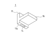
実施形態2に用いられる保持部材1は、太陽電池モジュール80のコーナー部81を下から受け止める構造であり、平面視L字状に屈曲形成された基体部11と、この基体部11の内側壁面から該壁面に直交する方向に延設された受け部(保持部)16とを備えている。
The holding
受け部16は、図4Cに示すように、太陽電池モジュール80のコーナー部81を下から受けるように形成されており、保持部材1全体の形状としては、縦断面略L字状に形成されている。
As shown in FIG. 4C, the receiving
また、基体部11の上端面11a及び下端面11bには、上下に隣接配置される別の保持部材1と順次嵌合するための嵌合凸部13及び嵌合凹部14がそれぞれ設けられている。実施形態2でも、嵌合凸部13は、基体部11の各片の上端面11aに1個ずつ、計2個設けられており、嵌合凹部14は、基体部11の各片の下端面11bに1個ずつ、計2個設けられている。ただし、嵌合凸部13及び嵌合凹部14の形成数はこれに限定されるものではなく、例えば基板部11の上端面11a及び下端面11bにそれぞれ2個ずつ、計4個設けられていてもよい。このような形状の保持部材1は、例えばPP(ポリプロピレン)やABS(アクリロニトリル・ブタジエン・スチレン共重合体)等の樹脂による射出成形によって形成されている。
Further, the
実施形態2では、このような形状の保持部材1を用いてフレームレス構造の太陽電池モジュールを水平に積み重ねて梱包する。
In the second embodiment, the solar cell modules having a frameless structure are horizontally stacked using the holding
多段積載方法は、図3A〜図3Hを用いて説明した実施形態1の多段積載方法と基本的に同じであるので、ここでは詳細な説明を省略するが、違うところは、図3C及び図3Dで示した第3工程において、太陽電池モジュール80のコーナー部81を保持部材1の挟持部12に横方向から嵌め合わせるのではなく、図5に示すように、保持部材1の受け部16上に横方向から載置するだけである。図5は、太陽電池モジュール80の積載状態のコーナー部を拡大して示す断面図である。
The multi-stage stacking method is basically the same as the multi-stage stacking method of the first embodiment described with reference to FIGS. 3A to 3H, and thus detailed description thereof is omitted here, but the differences are illustrated in FIGS. 3C and 3D. In the third step shown in FIG. 5, the
このような構成とすれば、太陽電池モジュール80のコーナー部81を保持部材1の受け部16上に単に載置するだけでよいので、高さ方向の位置合わせを正確に行わなくても、太陽電池モジュール80のコーナー部81を受け部16上に載置することができる。これにより、太陽電池モジュール80の積載・梱包作業の機械による自動化が容易となる。
With such a configuration, it is only necessary to place the
また、実施形態2の保持部材1を用いた場合には、図5に示すように、上下の太陽電池モジュール80の間に隙間Pが生じることになる。そして、太陽電池モジュール80のコーナー部81は、保持部材1の受け部16上に単に載置されているだけであるため、搬送時等の振動により、太陽電池モジュール80がこの隙間Pの間で上下に揺れることになる。ここで、隙間Pを設けている理由は、太陽電池モジュール80の裏面側に端子ボックス(図示省略)が取り付けられているため、太陽電池モジュール80を水平状態で多段に積載するためには、少なくともこの端子ボックスの厚み分以上の隙間を開ける必要があるからである。
Further, when the holding
そこで、実施形態2では、第5工程実施後、梱包前に、多段に積載された太陽電池モジュール80の間に緩衝部材5を挿入する工程を追加している。緩衝部材5を挿入することで、搬送時の太陽電池モジュール80の縦揺れを防止することができる。
Therefore, in the second embodiment, a step of inserting the
ここで、緩衝部材5としては、例えば発砲スチロールで形成した立方体形状または円柱形状の小片を、各太陽電池モジュール80間に差し込むようにしてもよいが、これでは手間がかかるため、例えば図6に示すように、櫛歯状に形成された一体構造の緩衝部材5を用意し、これを多段に積層された太電池モジュール80の各隙間Pに横方向から一体で差し込むようにしてもよい。そのため、緩衝部材5の各櫛歯部51の厚みT31は、隙間Pと略等しい厚みに形成され、櫛歯部51間の距離T32は、太陽電池モジュール80の厚みT41に略等しい距離に形成されている。これにより、実施形態1の保持部材1による挟持部12の挟持構造と同様、搬送時の縦揺れを防止することができる。
Here, as the
<実施形態3>
実施形態1,2では、保持部材1によって太陽電池モジュール80のコーナー部81を保持する構造であったが、実施形態3では、保持部材1によって太陽電池モジュール80の側端部、より具体的には、コーナー部81を除く長手方向に沿う両側端部を保持する構造としている。そのため、実施形態3では、保持部材1の形状が実施形態1とは異なっている。
<Embodiment 3>
In the first and second embodiments, the
図7A〜図7Cは、実施形態3に係る保持部材1の構造を示している。
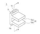
7A to 7C show the structure of the holding
実施形態3では、太陽電池モジュール80の側端部を保持するため、基体部11が平面視L字状ではなく、直線状となっている。すなわち、保持部材1は、太陽電池モジュール80のコーナー部81を除く長手方向に沿う両側端部82を横から嵌め合わせて保持する構造であり、平面視長方形状に形成された基体部11と、この基体部11の一方の側面から該側面に直交する方向に延設された挟持部12とを備えている。
In Embodiment 3, in order to hold | maintain the side edge part of the
挟持部12は、平行に配置された上側挟持片12aと下側挟持片12bとで構成され、図7Cに示すように、太陽電池モジュール80の側端部82を挟み込むように横向きに開口した縦断面コ字状に形成されている。
The sandwiching
また、基体部11の上端面11a及び下端面11bには、上下に隣接配置される別の保持部材1と順次嵌合するための嵌合凸部13及び嵌合凹部14がそれぞれ設けられている。実施形態3では、嵌合凸部13は、基体部11の各片の上端面11aに1個ずつ、計2個設けられており、嵌合凹部14は、基体部11の各片の下端面11bに1個ずつ、計2個設けられている。ただし、嵌合凸部13及び嵌合凹部14の形成数はこれに限定されるものではなく、例えば基板部11の上端面11a及び下端面11bにそれぞれ2個ずつ、計4個設けられていてもよい。このような形状の保持部材1は、例えばPP(ポリプロピレン)やABS(アクリロニトリル・ブタジエン・スチレン共重合体)等の樹脂による射出成形によって形成されている。
Further, the
実施形態3では、このような形状の保持部材1を用いてフレームレス構造の太陽電池モジュールを水平に積み重ねて梱包する。また、実施形態3の多段積載方法でも、図2に示す仮保持部材2を用いる。
In the third embodiment, the solar cell modules having a frameless structure are horizontally stacked using the holding
次に、上記各部材1,2を用いた実施形態3の多段積載方法について、図8Aないし図8Hに示す各工程図を参照して説明する。
Next, the multi-stage stacking method of the third embodiment using the
第1工程では、図8Aに示すように、多数用意した保持部材1を上下方向に所定数嵌合することにより、上下方向に一定の間隔を存して所定数の挟持部12が形成された長尺状の保持体1Aを作製する。ここで、実施形態3でも、太陽電池モジュール80を水平に10段積み重ねて一体梱包するものとし、1つの保持体1Aは、10個の保持部材1を上下一体に、かつ、着脱可能に嵌め合わせた構造としている。
In the first step, as shown in FIG. 8A, a predetermined number of holding
第2工程では、図8Bに示すように、このように作製した2つの保持体1Aを、太陽電池モジュール80の幅方向の幅T11に合わせて立設配置する。ここで、保持体1Aを立設させる手法としては、実施形態1と同様、図8Bに示すように、板状の立設基板4を用意し、この立設基板4に、保持体1Aの下端部(すなわち、最下段の保持部材1の基体部11の下端部15)が着脱可能に嵌まり込むように、I字状に形成された一対の貫通穴41,41を設けておき、この貫通穴41,41に各保持体1Aの下端部15を嵌め合わせることで、各保持体1Aを立設配置する構成としている。ただし、立設配置の手法はこのような構成に限定されるものではなく、例えば立設基板4の代わりに滑りにくいゴム状の基材を敷設し、ここに2つの保持体1Aを幅T11の間隔で立設配置し、上部を図示しない支持杆のようなもので横方向から支持するようにしてもよい。
In the second step, as shown in FIG. 8B, the two holding
第3工程では、図8C及び図8Dに示すように、立設配置された2つの保持体1Aの各挟持部12に、太陽電池モジュール80の幅方向に直交する長手方向の一方の両コーナー部(図8C中、左側の両コーナー部)81をそれぞれ横方向(図8C中、X方向)から嵌め合わせて若干通過させ、この嵌め合わせた状態で、2つの仮保持部材2を用いて太陽電池モジュール80の長手方向の中程(より具体的には、図8C中、右側のコーナー部81に近い箇所)を幅方向の両側から(図8C中、Y1方向から)挟み込むように仮保持して、太陽電池モジュール80を水平状態に保持する。
In the third step, as shown in FIG. 8C and FIG. 8D, one corner portion in the longitudinal direction perpendicular to the width direction of the
図8C及び図8Dでは、太陽電池モジュール80を保持体1Aの最下段から順次嵌め合わせる構成としているため、図8Dに示すように、下から1段目の太陽電池モジュール80は、保持体1Aの下から1段目の保持部材1の下側挟持片12bと仮保持部材2の下から1段目の腕杆23とによって支持されることになる。因みに、図8Dに示すように、保持体1Aと仮保持部材2とを立設した状態で、各段の保持部材1の下側挟持片12bと仮保持部材2の各段の腕杆23とは、同じ高さとなるように設けられている。
8C and 8D, since the
次に、図8E及び図8Fに示すように、仮保持部材2の下から2段目の腕杆23上を通して、2つの保持体1Aの下から2段目の保持部材1の挟持部12に、2段目の太陽電池モジュール80の長手方向の一方の両コーナー部81をそれぞれ横方向(図8E中、X方向)から嵌め合わせて若干通過させる。これにより、図8Fに示すように、保持体1Aの下から2段目の保持部材1の下側挟持片12bと仮保持部材2の下から2段目の腕杆23とによって、下から2段目の太陽電池モジュール80が支持されることになる。
Next, as shown in FIG. 8E and FIG. 8F, it passes over the
この第3工程を10回繰り返すこと(第4工程)により、立設配置された2つの保持体1Aと2つの仮保持部材2とによって、10個の太陽電池モジュール80が水平状態で多段に積載される。
By repeating the third step 10 times (fourth step), ten
第5工程では、図8Gに示すように、水平状態で仮保持された10個の太陽電池モジュール80の長手方向の他方の両コーナー部(図8G中、右側の両コーナー部)81寄りの側端部82に、別に作製した2つの保持体1Aの挟持部12をそれぞれ横方向(図8G中、Y1方向)から嵌め合わせて、2つの保持体1Aを立設配置する。これにより、10個の太陽電池モジュール80は、4本の保持体1Aによって側端部82の4箇所が保持されることになる。この後、対向している2つの仮保持部材2を幅方向に広げるように移動(図8G中、Y2方向に移動)させることで、仮保持部材2の腕杆23を太陽電池モジュール80の間から引き抜く。
In the fifth step, as shown in FIG. 8G, the other two corner portions in the longitudinal direction of the ten
以上により、図8Hに示すように、10個の太陽電池モジュール80が水平状態で積み重ねられたので、この後は、図示しない梱包工程を実施して、4つの保持体1Aに保持された10個の太陽電池モジュール80を一体に梱包する。
As described above, as shown in FIG. 8H, the ten
なお、このような梱包に際しては、立設基板4も除去される。すなわち、立設基板4は、最初の2つの保持体1Aを立設させるためのものであり、4本の保持体1Aで10個の太陽電池モジュール80を支持した後は、不要である。すなわち、立設基板4も仮保持部材2と同様、新たな梱包を行うたびに再利用されるリユース部材である。
Note that the standing
以上説明したように、実施形態3の多段積載方法では、最初に位置固定するのは2つの保持体1Aのみであり、残り2つの保持体1Aは、多段に積載した太陽電池モジュール80の両側縁部82に、挟持部12をそれぞれ単に嵌め合わせることによって、最終的な位置決めが行われることになる。すなわち、太陽電池モジュール80の寸法誤差に影響されることなく、各保持体1Aを太陽電池モジュール80の両側縁部82に嵌合することができるため、機械による自動梱包化が容易となる。
As described above, in the multi-stage stacking method of the third embodiment, only the two holding
また、太陽電池モジュール80の側端部82を保持部材1の挟持部12に嵌め合わせることで、上下方向のがたつきも防止することができる。すなわち、搬送時の振動に対して、太陽電池モジュール80の縦揺れを防止することができる。
Further, by fitting the
さらにまた、実施形態3の多段積載方法では、フレームレス構造の太陽電池モジュールの梱包作業を、太陽電池モジュールのガラス端部の破損を防止しつつ、効率よく行うことができる。 Furthermore, in the multi-stage stacking method according to the third embodiment, the packing operation of the solar cell module having the frameless structure can be efficiently performed while preventing the glass end portion of the solar cell module from being damaged.
なお、実施形態3では、太陽電池モジュール80を多段に積載していく第3工程の繰り返し(すなわち、第4工程)を、最下段から始めて最上段まで実施する構成としているが、これとは逆に、最上段から始めて最下段まで実施する構成としてもよい。
In the third embodiment, the repetition of the third step of stacking the
<実施形態4>
実施形態4の多段積載方法も、実施形態3の多段積載方法と基本的に同じであるが、使用する保持部材1の形状が異なっている。
<
The multi-stage stacking method of the fourth embodiment is basically the same as the multi-stage stacking method of the third embodiment, but the shape of the holding
図9A〜図9Cは、実施形態4に係る太陽電池モジュールの多段積載方法に用いられる保持部材の構成を示す図であり、図9Aは斜め上方からみた斜視図、図9Bは斜め下方からみた斜視図、図9Cは、図9AのVIII−VIII線断面図である。
9A to 9C are diagrams showing a configuration of a holding member used in the multi-stage stacking method for solar cell modules according to
実施形態4に用いられる保持部材1は、太陽電池モジュール80の側端部82を下から受け止める構造であり、平面視長方形状に形成された基体部11と、この基体部11の一方の側面から該側面に直交する方向に延設された受け部16とを備えている。
The holding
受け止16は、図9Cに示すように、太陽電池モジュール80の側端部82を下から受けるように形成されており、保持部材1全体の形状としては、縦断面略L字状に形成されている。
As shown in FIG. 9C, the
また、基体部11の上端面11a及び下端面11bには、上下に隣接配置される別の保持部材1と順次嵌合するための嵌合凸部13及び嵌合凹部14がそれぞれ設けられている。実施形態4でも、嵌合凸部13は、基体部11の各片の上端面11aに1個ずつ、計2個設けられており、嵌合凹部14は、基体部11の各片の下端面11bに1個ずつ、計2個設けられている。ただし、嵌合凸部13及び嵌合凹部14の形成数はこれに限定されるものではなく、例えば基板部11の上端面11aと下端面11bとに2個ずつ、計4個設けられていてもよい。このような形状の保持部材1は、例えばPP(ポリプロピレン)やABS(アクリロニトリル・ブタジエン・スチレン共重合体)等の樹脂による射出成形によって形成されている。
Further, the
実施形態4では、このような形状の保持部材1を用いてフレームレス構造の太陽電池モジュールを水平に積み重ねて梱包する。
In the fourth embodiment, the solar cell modules having the frameless structure are stacked horizontally and packed using the holding
多段積載方法は、図7A〜図7Hを用いて説明して実施形態3の多段積載方法と基本的に同じであるので、ここでは詳細な説明を省略する。 The multi-stage stacking method is basically the same as the multi-stage stacking method according to the third embodiment described with reference to FIGS. 7A to 7H, and detailed description thereof is omitted here.
このような構成とすれば、太陽電池モジュール80の側端部82を保持部材1の受け部16上に単に載置するだけでよいので、高さ方向の位置合わせを正確に行わなくても、太陽電池モジュール80の側端部82を受け部16上に載置することができる。これにより、太陽電池モジュール80の積載・梱包作業の機械による自動化が容易となる。
With such a configuration, it is only necessary to place the
また、実施形態4の保持部材1を用いた場合も、実施形態2で説明した図5に示すように、上下の太陽電池モジュール80の間に隙間Pが生じることになる。そして、太陽電池モジュール80の側端部82は、保持部材1の受け部16上に単に載置されているだけであるため、搬送時等の振動により、太陽電池モジュール80がこの隙間Pの間で上下に揺れることになる。
Further, when the holding
そこで、実施形態4でも、実施形態2と同様に、第5工程終了後、梱包前に、多段に積載された太陽電池モジュール80の間に緩衝部材5を挿入する工程を追加している。緩衝部材5を挿入することで、搬送時の太陽電池モジュール80の縦揺れを防止することができる。
Therefore, in the fourth embodiment, as in the second embodiment, after the fifth step is completed, a step of inserting the
緩衝部材5としては、実施形態2で説明した図6に示すように、櫛歯状に形成された一体構造の緩衝部材5を用いることができる。
As the
ここで、実施形態4では、保持部材1は太陽電池モジュール80の側端部82を支持(保持)しているため、多段に積載された状態で太陽電池モジュール80のコーナー部81が露出した状態となる。コーナー部81は、僅かな衝撃でも破損しやすい箇所であるため、実施形態4では、図6に示す緩衝部材5を、このコーナー部81に差し込むようにしてもよい。この場合には、図10に示すように、4隅すべてのコーナー部81にそれぞれ緩衝部材5を差し込むことになる。これにより、実施形態3の保持部材1による挟持部12の挟持構造と同様、搬送時の縦揺れを防止しつつ、コーナー部81の破損も防止することができる。
Here, in the fourth embodiment, since the holding
なお、今回開示した実施形態はすべての点で例示であって、限定的な解釈の根拠となるものではない。従って、本発明の技術的範囲は、上記した実施形態のみによって解釈されるものではなく、特許請求の範囲の記載に基づいて画定される。また、特許請求の範囲と均等の意味及び範囲内でのすべての変更が含まれる。 In addition, embodiment disclosed this time is an illustration in all the points, Comprising: It does not become the basis of limited interpretation. Therefore, the technical scope of the present invention is not interpreted only by the above-described embodiments, but is defined based on the description of the scope of claims. Moreover, all the changes within the meaning and range equivalent to a claim are included.
1 保持部材
1A 保持体
2 仮保持部材
4 設置基板
5 緩衝部材
11 基体部
11a 上端面
11b 下端面
12 挟持部(保持部)
12a 上側挟持片
12b 下側挟持片
13 嵌合凸部(嵌合部)
14 嵌合凹部(嵌合部)
15 下端部
16 受け部(保持部)
21 支持基板
22 支柱
23 腕杆
41 貫通穴
51 櫛歯部
80 太陽電池モジュール
81 コーナー部
82 側端部
DESCRIPTION OF
12a
14 Fitting recess (fitting part)
15
DESCRIPTION OF
Claims (7)
前記保持部材は、前記太陽電池モジュールの端部を嵌め合わせて保持する保持部と、上下に隣接する他の保持部材と上下方向に嵌合する嵌合部とを備えており、
前記保持部材を上下方向に所定数嵌合することにより、上下方向に一定の間隔を存して所定数の前記保持部が形成された長尺状の保持体を作製する第1工程と、
作製した2つの保持体を前記太陽電池モジュールの第1の方向の幅に合わせて立設配置する第2工程と、
立設配置された前記2つの保持体の横方向に対向する2つの保持部に、太陽電池モジュールの前記第1の方向に直交する第2の方向の一方寄りの両端部をそれぞれ嵌め合わせて前記太陽電池モジュールを水平状態で仮保持する第3工程と、
前記第3工程を、立設配置された前記2つの保持体の横方向に対向する2つの保持部の最下段から最上段まで、または最上段から最下段まで所定回数繰り返す第4工程と、
前記第4工程終了後、水平状態で仮保持された前記所定数の太陽電池モジュールの前記第2の方向の他方寄りの両端部に、別に作製した2つの保持体の対向す保持部をそれぞれ嵌め合わせて前記2つの保持体を立設配置する第5工程と、
を含むことを特徴とする太陽電池モジュールの多段積載方法。 A method of stacking the solar cell modules in multiple stages using holding members that respectively hold both ends of the rectangular solar cell module facing in one direction,
The holding member includes a holding portion that fits and holds the end portion of the solar cell module, and a fitting portion that fits in the vertical direction with another holding member that is adjacent vertically.
A first step of producing a long holding body in which a predetermined number of the holding portions are formed at a certain interval in the vertical direction by fitting a predetermined number of the holding members in the vertical direction;
A second step of standing and arranging the produced two holding bodies in accordance with the width of the solar cell module in the first direction;
The two holding parts opposed to each other in the lateral direction of the two holding bodies arranged upright are fitted to both ends of the solar cell module near one side in the second direction perpendicular to the first direction, respectively. A third step of temporarily holding the solar cell module in a horizontal state;
A fourth step of repeating the third step a predetermined number of times from the lowest level to the highest level or from the highest level to the lowest level of the two holding parts opposed in the lateral direction of the two holding bodies arranged upright;
After completion of the fourth step, two opposing holding parts of the two separately prepared holding bodies are respectively fitted to both ends of the predetermined number of solar cell modules temporarily held in a horizontal state near the other side of the second direction. And a fifth step of standing and arranging the two holding bodies together,
A multi-stage stacking method for solar cell modules, comprising:
前記第3工程では、前記2つの保持体とは別に仮保持部材を用いて前記太陽電池モジュールを水平状態で仮保持することを特徴とする太陽電池モジュールの多段積載方法。 It is a multistage loading method of the solar cell module according to claim 1,
In the third step, the solar cell module is temporarily held in a horizontal state by using a temporary holding member separately from the two holding bodies.
前記太陽電池モジュールの一方向に対向する両端部が、前記太陽電池モジュールの一方向に対向する両コーナー部であることを特徴とする太陽電池モジュールの多段積載方法。 A multi-stage stacking method for solar cell modules according to claim 1 or 2,
The solar battery module multi-stage stacking method, wherein both end portions facing the solar cell module in one direction are both corner portions facing the solar cell module in one direction.
前記保持部は、前記太陽電池モジュールの端部を挟み込むように断面コ字状に形成されていることを特徴とする太陽電池モジュールの多段積載方法。 It is the multistage loading method of the solar cell module of any one of Claim 1- Claim 3,
The said holding | maintenance part is formed in the cross-sectional U shape so that the edge part of the said solar cell module may be inserted | pinched, The multistage loading method of the solar cell module characterized by the above-mentioned.
前記保持部は、前記太陽電池モジュールの端部を下から受け止めるように縦断面L字状に形成されていることを特徴とする太陽電池モジュールの多段積載方法。 It is the multistage loading method of the solar cell module of any one of Claim 1- Claim 3,
The said holding | maintenance part is formed in the longitudinal cross-section L shape so that the edge part of the said solar cell module may be received from the bottom, The multistage loading method of the solar cell module characterized by the above-mentioned.
前記第5工程終了後に、多段に積載された前記太陽電池モジュールの間に緩衝部材を挿入する工程が含まれることを特徴とする太陽電池モジュールの多段積載方法。 A multi-stage stacking method for solar cell modules according to claim 5,
A multi-stage stacking method for solar cell modules, comprising a step of inserting a buffer member between the solar cell modules stacked in multiple stages after the fifth step.
前記太陽電池モジュールがフレームレス構造の太陽電池モジュールであることを特徴とする太陽電池モジュールの多段積載方法。 It is the multistage loading method of the solar cell module of any one of Claim 1- Claim 6,
The solar cell module is a solar cell module having a frameless structure.
Priority Applications (1)
| Application Number | Priority Date | Filing Date | Title |
|---|---|---|---|
| JP2011050646A JP2012190844A (en) | 2011-03-08 | 2011-03-08 | Method for multiple stage of solar cell module |
Applications Claiming Priority (1)
| Application Number | Priority Date | Filing Date | Title |
|---|---|---|---|
| JP2011050646A JP2012190844A (en) | 2011-03-08 | 2011-03-08 | Method for multiple stage of solar cell module |
Publications (1)
| Publication Number | Publication Date |
|---|---|
| JP2012190844A true JP2012190844A (en) | 2012-10-04 |
Family
ID=47083734
Family Applications (1)
| Application Number | Title | Priority Date | Filing Date |
|---|---|---|---|
| JP2011050646A Withdrawn JP2012190844A (en) | 2011-03-08 | 2011-03-08 | Method for multiple stage of solar cell module |
Country Status (1)
| Country | Link |
|---|---|
| JP (1) | JP2012190844A (en) |
Cited By (5)
| Publication number | Priority date | Publication date | Assignee | Title |
|---|---|---|---|---|
| JP2014162516A (en) * | 2013-02-26 | 2014-09-08 | Sekisui Plastics Co Ltd | Packing body and packing material |
| KR101610239B1 (en) | 2014-09-17 | 2016-04-07 | 정영식 | Space adjusting device for drying rack |
| KR101819136B1 (en) | 2016-03-30 | 2018-01-16 | 인하대학교 산학협력단 | Shipping rack for tower module sections of wind turbine |
| WO2018043233A1 (en) * | 2016-09-02 | 2018-03-08 | パナソニックIpマネジメント株式会社 | Solar cell module, packaging mode therefor, and solar power generation device |
| US10305074B2 (en) | 2016-01-26 | 2019-05-28 | Samsung Sdi Co., Ltd. | Battery assembly |
-
2011
- 2011-03-08 JP JP2011050646A patent/JP2012190844A/en not_active Withdrawn
Cited By (7)
| Publication number | Priority date | Publication date | Assignee | Title |
|---|---|---|---|---|
| JP2014162516A (en) * | 2013-02-26 | 2014-09-08 | Sekisui Plastics Co Ltd | Packing body and packing material |
| KR101610239B1 (en) | 2014-09-17 | 2016-04-07 | 정영식 | Space adjusting device for drying rack |
| US10305074B2 (en) | 2016-01-26 | 2019-05-28 | Samsung Sdi Co., Ltd. | Battery assembly |
| KR101819136B1 (en) | 2016-03-30 | 2018-01-16 | 인하대학교 산학협력단 | Shipping rack for tower module sections of wind turbine |
| WO2018043233A1 (en) * | 2016-09-02 | 2018-03-08 | パナソニックIpマネジメント株式会社 | Solar cell module, packaging mode therefor, and solar power generation device |
| CN109804555A (en) * | 2016-09-02 | 2019-05-24 | 松下知识产权经营株式会社 | Solar cell module, its bale packing mode and device of solar generating |
| JPWO2018043233A1 (en) * | 2016-09-02 | 2019-07-11 | パナソニックIpマネジメント株式会社 | Photovoltaic module, its packing form, and solar power generation apparatus |
Similar Documents
| Publication | Publication Date | Title |
|---|---|---|
| US20140367305A1 (en) | Supporting structure, loading and packing device, supporting base plate, and packing method | |
| US9409702B2 (en) | Rectangular thin panel conveyance unit | |
| CN104080712B (en) | The delivery unit of thin plate panels | |
| JP2012091866A (en) | Module used for stacking thin panels and method of stacking thin panels | |
| US9352900B2 (en) | Support frame for packaging liquid crystal glass panel | |
| JP4988886B2 (en) | Corner support member for packaging panel materials | |
| WO2013118808A1 (en) | Metallic pallet | |
| WO2019127795A1 (en) | Liquid crystal panel packaging box | |
| JP5901961B2 (en) | Support structure and packing method | |
| JP2014019486A (en) | Corner supporting mechanism for packaging panel material | |
| JP2013169999A (en) | Loading and packaging device, and packaging method | |
| JP2012188122A (en) | Multi-stage loading device for solar cell module and method for multi-stage loading of the solar cell module using the same | |
| JP2013154928A (en) | Solar cell module loading device and solar cell module loading unit | |
| JP2013129444A (en) | Holding structure | |
| JP2011051648A (en) | Packing material for solar battery panel | |
| JP6069285B2 (en) | Accommodation rack | |
| JP2011051643A (en) | Packing material for solar battery panel | |
| KR20110085306A (en) | Packaging Blocks and Assemblies for Backlight Unit Transport | |
| JP2013133161A (en) | Solar cell module loading unit | |
| JP5063796B1 (en) | Packing structure and packing method | |
| JP5401983B2 (en) | Assembled container | |
| JP5665525B2 (en) | Plate-shaped body placing device and plate-shaped body conveying device | |
| JP2023018311A (en) | storage rack | |
| JP2013131648A (en) | Loading packaging tool and packaging method | |
| WO2013065592A1 (en) | Support structure, unit formed by stacking solar cell modules in multiple stages using support structure, and method for stacking solar cell modules in multiple stages using support structure |
Legal Events
| Date | Code | Title | Description |
|---|---|---|---|
| A300 | Application deemed to be withdrawn because no request for examination was validly filed |
Free format text: JAPANESE INTERMEDIATE CODE: A300 Effective date: 20140513 |