JP2012192477A - 剛平行弾性体及び剛平行弾性体の駆動方法 - Google Patents
剛平行弾性体及び剛平行弾性体の駆動方法 Download PDFInfo
- Publication number
- JP2012192477A JP2012192477A JP2011057763A JP2011057763A JP2012192477A JP 2012192477 A JP2012192477 A JP 2012192477A JP 2011057763 A JP2011057763 A JP 2011057763A JP 2011057763 A JP2011057763 A JP 2011057763A JP 2012192477 A JP2012192477 A JP 2012192477A
- Authority
- JP
- Japan
- Prior art keywords
- main body
- central axis
- elastic body
- hinge mechanism
- recess
- Prior art date
- Legal status (The legal status is an assumption and is not a legal conclusion. Google has not performed a legal analysis and makes no representation as to the accuracy of the status listed.)
- Granted
Links
- 238000000034 method Methods 0.000 title claims abstract description 7
- 238000003825 pressing Methods 0.000 claims abstract description 19
- 230000005489 elastic deformation Effects 0.000 claims description 3
- 238000004519 manufacturing process Methods 0.000 abstract description 7
- 238000006073 displacement reaction Methods 0.000 description 8
- 230000004323 axial length Effects 0.000 description 5
- 230000000149 penetrating effect Effects 0.000 description 5
- 238000005520 cutting process Methods 0.000 description 3
- 238000006243 chemical reaction Methods 0.000 description 1
- 238000005304 joining Methods 0.000 description 1
- 239000007787 solid Substances 0.000 description 1
Images


Landscapes
- Drilling And Boring (AREA)
- Cutting Tools, Boring Holders, And Turrets (AREA)
Abstract
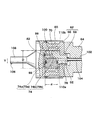
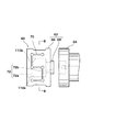
【解決手段】本体12の中心軸の軸方向に形成される凹部18内に、本体12の中心軸に対して直角方向に配置される互いに対向する壁面37a,37bを有する。本体12の凹部18内に、壁面37a,37bを反対側に押圧する第一腕部30と第二腕部32とを有するヒンジ機構24を収容する。ピストン26でヒンジ機構24を凹部18内に押圧することで、第一腕部30と第二腕部32とが互いに対向する壁面37a,37bを離れる方向に押圧し、ボーリングバー108に備えられたチップ106の位置を微小補正する。
【選択図】図1
Description
12 本体
18 凹部
18b 第二凹部
20 駆動手段
22 バックプレート
24 ヒンジ機構
26 ピストン
28 ピン
30 第一腕部
32 第二腕部
37a 壁面
37b 壁面
54 圧力室
56 油連絡通路
64 主軸
70 貫通スリット
70a 平行貫通箇所
70b 平行貫通箇所
104 油供給通路
Claims (6)
- 中心軸を中心に回転させられる本体と、前記本体の中心軸の軸方向に前記本体の内部に形成される凹部と、前記本体を貫通して形成されるものであって前記凹部の中心軸を中心に互いに反対側に前記中心軸に平行に形成された平行貫通箇所を有する貫通スリットと、前記凹部内に備えられるものであって前記凹部の対向する一対の壁面を前記本体の中心軸に対して直角方向に反対側に押圧するための駆動手段とを有する剛平行弾性体において、前記駆動手段が、前記凹部内で軸方向に移動可能に備えられるピンとそのピンを中心に回転可能で前記一対の壁面を押圧する第一腕部と第二腕部とから成るヒンジ機構と、前記ヒンジ機構を前記本体の中心軸方向で前記凹部の奥側に向けて前記ヒンジ機構を押圧して前記第一腕部と前記第二腕部で互いに対向する前記一対の壁面を押圧するためのピストンと、を備えたことを特徴とする剛平行弾性体。
- 前記駆動手段は、前記凹部における前記ヒンジ機構の位置より奥側に収容するものであって前記ヒンジ機構の前記第一腕部と前記第二腕部の軸方向の力を受けるためのバックプレートを有することを特徴とする請求項1記載の剛平行弾性体。
- 前記バックプレートと前記ヒンジ機構とを収容する位置の前記凹部の断面形状を矩形としたことを特徴とする請求項1または2記載の剛平行弾性体。
- 前記ピストンを中心位置として前記ヒンジ機構の反対側に設けられる圧力室と、前記本体に設けられるもので一方を油供給現源と連絡し他方を前記油圧室と連絡する油連絡通路とを有し、前記油供給源からの油を前記油導入通路を経由して前記油圧室に導入することを特徴とする請求項1乃至3のいずれか1項記載の剛平行弾性体。
- 中心軸を中心に回転させられる本体と、前記本体の中心軸の軸方向に前記本体の内部に形成される凹部と、前記本体を貫通して形成されるものであって前記凹部の中心軸を中心に互いに反対側に前記中心軸に平行に形成された平行貫通箇所を有する貫通スリットと、前記凹部内に備えられるものであって前記凹部の対向する一対の壁面を前記本体の中心軸に対して直角方向に反対側に押圧するための駆動手段とを有する剛平行弾性体において、前記凹部内に軸方向に移動可能に備えられるピンとそのピンを中心とそのピンを中心に回転可能な第一腕部と第二腕部とから成るヒンジ機構を前記凹部内に収納し、前記ヒンジ機構をピストンで前記凹部の奥側に押圧することで前記凹部の対向する一対の壁面を前記第一腕部と前記第二腕部で押圧して前記本体に弾性変形を生じさせることを特徴とする剛平行弾性体の駆動方法。
- 前記ピストンを中心位置として前記ヒンジ機構の反対側に設けられる圧力室と、前記本体に設けられるもので一方を油供給現源と連絡し他方を前記油圧室と連絡する油連絡通路とを有し、前記油供給源からの油を前記油導入通路を経由して前記油圧室に導入することを特徴とする請求項5項記載の剛平行弾性体の駆動方法。
Priority Applications (1)
| Application Number | Priority Date | Filing Date | Title |
|---|---|---|---|
| JP2011057763A JP5726580B2 (ja) | 2011-03-16 | 2011-03-16 | 平行弾性体及び平行弾性体の駆動方法 |
Applications Claiming Priority (1)
| Application Number | Priority Date | Filing Date | Title |
|---|---|---|---|
| JP2011057763A JP5726580B2 (ja) | 2011-03-16 | 2011-03-16 | 平行弾性体及び平行弾性体の駆動方法 |
Publications (2)
| Publication Number | Publication Date |
|---|---|
| JP2012192477A true JP2012192477A (ja) | 2012-10-11 |
| JP5726580B2 JP5726580B2 (ja) | 2015-06-03 |
Family
ID=47084887
Family Applications (1)
| Application Number | Title | Priority Date | Filing Date |
|---|---|---|---|
| JP2011057763A Active JP5726580B2 (ja) | 2011-03-16 | 2011-03-16 | 平行弾性体及び平行弾性体の駆動方法 |
Country Status (1)
| Country | Link |
|---|---|
| JP (1) | JP5726580B2 (ja) |
Citations (3)
| Publication number | Priority date | Publication date | Assignee | Title |
|---|---|---|---|---|
| DE2409721A1 (de) * | 1974-03-01 | 1975-09-04 | Georg Gert Frederichs | Hydrodynamische abhebung von drehschneiden und werkzeugen an drehspindeln zwecks von drehflaeche freies zurueckfahren bei umlaufender drehspindel |
| JPS50154892A (ja) * | 1974-06-05 | 1975-12-13 | ||
| US5304019A (en) * | 1992-06-04 | 1994-04-19 | Samson Ag | Rotating drill head with a boring bar which is pivotable by a slight distance transversely to the axis of rotation by fluidic means |
-
2011
- 2011-03-16 JP JP2011057763A patent/JP5726580B2/ja active Active
Patent Citations (4)
| Publication number | Priority date | Publication date | Assignee | Title |
|---|---|---|---|---|
| DE2409721A1 (de) * | 1974-03-01 | 1975-09-04 | Georg Gert Frederichs | Hydrodynamische abhebung von drehschneiden und werkzeugen an drehspindeln zwecks von drehflaeche freies zurueckfahren bei umlaufender drehspindel |
| JPS50154892A (ja) * | 1974-06-05 | 1975-12-13 | ||
| US5304019A (en) * | 1992-06-04 | 1994-04-19 | Samson Ag | Rotating drill head with a boring bar which is pivotable by a slight distance transversely to the axis of rotation by fluidic means |
| JPH06320307A (ja) * | 1992-06-04 | 1994-11-22 | Samson Ag | ドリルロッドの回転軸に対して直交する方向に流体によって微調節できる回転ドリルヘッド |
Also Published As
| Publication number | Publication date |
|---|---|
| JP5726580B2 (ja) | 2015-06-03 |
Similar Documents
| Publication | Publication Date | Title |
|---|---|---|
| JP5441873B2 (ja) | 外接歯車ポンプ | |
| JP5282681B2 (ja) | ベーンポンプ | |
| CN120265862A (zh) | 往复组件中用于调整施力的构件 | |
| JP5798250B2 (ja) | ギヤポンプ | |
| JP4584303B2 (ja) | パワーステアリング装置およびその製造方法 | |
| JP2012192477A (ja) | 剛平行弾性体及び剛平行弾性体の駆動方法 | |
| US10941837B2 (en) | Reclining apparatus | |
| CN101396749B (zh) | 刀锯机的刀锯夹持装置 | |
| EP2738389A1 (en) | Internal gear pump | |
| JPH11247759A (ja) | 圧縮機及び圧縮機のピストン組付方法 | |
| JP2005163607A (ja) | ベーン式バキュームポンプとバキュームポンプにおけるロータ及びカップリングの製造方法 | |
| JP5106000B2 (ja) | 可変容量型ベーンポンプ | |
| JP7849315B2 (ja) | ダイヤフラムポンプ | |
| CN103492710B (zh) | 斜轴式轴向活塞马达 | |
| JP6554294B2 (ja) | トロイダル無段変速機及び航空機用駆動機構一体型発電装置 | |
| JP2015014196A (ja) | ベーン挿入治具及びこれを用いた圧縮機の組み付け方法 | |
| JP2020204288A (ja) | エアモータ | |
| US9283606B2 (en) | Method of manufacturing supporting structure, swaging jig for use therein and the supporting structure | |
| WO2018051904A1 (ja) | 可変容量型ベーンポンプ | |
| JP5639939B2 (ja) | 対向式斜板型ピストンポンプ・モータ | |
| JP2020180569A (ja) | ベーンポンプ | |
| JPH0531271Y2 (ja) | ||
| JP3911696B2 (ja) | 流体圧シリンダの取付構造 | |
| JP4961194B2 (ja) | 可変容量型斜板ポンプ・モータのベアリング保持装置および可変容量型斜板ポンプ・モータ | |
| JP2000136802A (ja) | 減圧弁型パイロット弁 |
Legal Events
| Date | Code | Title | Description |
|---|---|---|---|
| RD13 | Notification of appointment of power of sub attorney |
Free format text: JAPANESE INTERMEDIATE CODE: A7433 Effective date: 20130328 |
|
| A521 | Request for written amendment filed |
Free format text: JAPANESE INTERMEDIATE CODE: A523 Effective date: 20130419 |
|
| A621 | Written request for application examination |
Free format text: JAPANESE INTERMEDIATE CODE: A621 Effective date: 20140218 |
|
| A977 | Report on retrieval |
Free format text: JAPANESE INTERMEDIATE CODE: A971007 Effective date: 20141121 |
|
| A131 | Notification of reasons for refusal |
Free format text: JAPANESE INTERMEDIATE CODE: A131 Effective date: 20141202 |
|
| A521 | Request for written amendment filed |
Free format text: JAPANESE INTERMEDIATE CODE: A523 Effective date: 20150128 |
|
| TRDD | Decision of grant or rejection written | ||
| A01 | Written decision to grant a patent or to grant a registration (utility model) |
Free format text: JAPANESE INTERMEDIATE CODE: A01 Effective date: 20150303 |
|
| A61 | First payment of annual fees (during grant procedure) |
Free format text: JAPANESE INTERMEDIATE CODE: A61 Effective date: 20150401 |
|
| R150 | Certificate of patent or registration of utility model |
Ref document number: 5726580 Country of ref document: JP Free format text: JAPANESE INTERMEDIATE CODE: R150 |
|
| R250 | Receipt of annual fees |
Free format text: JAPANESE INTERMEDIATE CODE: R250 |
|
| R250 | Receipt of annual fees |
Free format text: JAPANESE INTERMEDIATE CODE: R250 |