JP2012192510A - Method for manufacturing total type grinding wheel - Google Patents
Method for manufacturing total type grinding wheel Download PDFInfo
- Publication number
- JP2012192510A JP2012192510A JP2011060273A JP2011060273A JP2012192510A JP 2012192510 A JP2012192510 A JP 2012192510A JP 2011060273 A JP2011060273 A JP 2011060273A JP 2011060273 A JP2011060273 A JP 2011060273A JP 2012192510 A JP2012192510 A JP 2012192510A
- Authority
- JP
- Japan
- Prior art keywords
- grindstone
- grinding
- truer
- general
- processing
- Prior art date
- Legal status (The legal status is an assumption and is not a legal conclusion. Google has not performed a legal analysis and makes no representation as to the accuracy of the status listed.)
- Withdrawn
Links
Images




Landscapes
- Grinding-Machine Dressing And Accessory Apparatuses (AREA)
Abstract
【課題】本発明は、1回の研削だけで、所望の形状の総型砥石が得られる総型砥石の製造方法を提供する。
【解決手段】縁部を面取り前の円板状の加工用砥石11を水平回転させつつ、水平に保持した円柱形状のツルアー2を、加工用砥石11の縁部に、該縁部が断面円弧状に面取りされるよう上下動させながら接触させるとともに加工用砥石11の中心に向けて前進させる研削工程を有する総型砥石の製造方法であって、上記研削工程において、ツルアー2の工具軌跡を、総型砥石の加工形状にツルアー2の研削後の半径(r´)だけ離間した軌跡とする総型砥石の製造方法。
【選択図】図2An object of the present invention is to provide a method for producing a general-purpose grindstone that can obtain a general-purpose grindstone having a desired shape by only one grinding.
A disk-shaped processing grinder 11 before chamfering an edge is horizontally rotated, and a columnar truer 2 held horizontally is placed on the edge of the processing grindstone 11, and the edge is a cross-sectional circle. A method of manufacturing a general-purpose grindstone having a grinding process in which it is moved while moving up and down so as to be chamfered in an arc shape and advanced toward the center of the processing grindstone 11, wherein the tool locus of the truer 2 is A method for producing a general-purpose grindstone having a locus separated by a radius (r ′) after grinding of the truer 2 in the processed shape of the general-purpose grindstone.
[Selection] Figure 2
Description
本発明は、成形型を加工するための総型砥石を、1回の研削で所望形状とできる総型砥石の製造方法に係り、特に、シリンドリカルレンズやトロイダルレンズ等のレンズ用成形型の加工に適した総型砥石の製造方法に関する。 The present invention relates to a method for manufacturing a general-purpose grindstone capable of forming a general-purpose grindstone for processing a mold into a desired shape by a single grinding operation, and particularly for processing a mold for a lens such as a cylindrical lens or a toroidal lens. The present invention relates to a method for producing a suitable general-purpose grindstone.
総型砥石は、研削加工機のツルアーを所定の工具軌跡を描くように往復運動させながら加工用砥石と接触させて、加工用砥石が所望の形状になるように研削し、製造されている。 The total-type grindstone is manufactured by bringing the grinder of the grinding machine into contact with the processing grindstone while reciprocating it so as to draw a predetermined tool path, and grinding the grindstone for processing into a desired shape.
一般に、工具軌跡は、研削後に得られる総型砥石の研削面の表面形状に対してツルアーの半径分だけ離間させた距離を描くように設定される。これは、ツルアーの総型砥石との接触表面が、目的とする総型砥石の表面形状を描くため、研削に好適であるとして用いられている。 In general, the tool trajectory is set so as to draw a distance separated by the radius of the truer with respect to the surface shape of the grinding surface of the total-type grindstone obtained after grinding. This is used as being suitable for grinding because the contact surface of the truer with the total type grindstone describes the surface shape of the target total type grindstone.
ところが、このような工具軌跡としても、実際には研削する際に、研削加工機等に起因する種々の誤差要因による形状誤差を有するため、所望の形状への精度の良い加工ができなかった。 However, even with such a tool trajectory, in actual grinding, there are shape errors due to various error factors caused by a grinding machine or the like, so that it has not been possible to accurately process the desired shape.
そこで、加工された総型砥石の表面形状を測定し、その表面形状と目的の表面形状との加工誤差を算出して、この加工誤差に基づいて、総型砥石の修正加工を少なくとも1回、多くの場合は複数回の修正加工を行うことで、所望の総型砥石を得ていた(例えば、特許文献1参照)。 Therefore, the surface shape of the machined grindstone is measured, a machining error between the surface shape and the target surface shape is calculated, and based on the machining error, the grindstone is corrected at least once. In many cases, a desired total grinding wheel has been obtained by performing correction processing a plurality of times (see, for example, Patent Document 1).
しかしながら、特許文献1の発明においては、従来と同様、形状誤差が出ること自体を改善するものではなく、形状誤差が出た砥石に対して、さらに同様の研削を行うことで、目的の表面形状へと近づけていくもので、加工するたびに表面形状を確認し、その誤差を修正する修正加工を行うため、操作が煩雑で、複数回の加工を行うため、効率的な加工方法ではなかった。
However, the invention of
そこで、本発明は上記問題点を解決するためになされたもので、総型砥石を研削加工機により加工して得る際に、1回の研削だけで、所望の形状の総型砥石が得られる総型砥石の製造方法の提供を目的とする。 Therefore, the present invention has been made to solve the above-mentioned problems, and when a total-type grindstone is processed by a grinding machine, a total-type grindstone having a desired shape can be obtained by only one grinding. It aims at providing the manufacturing method of a total type grindstone.
本発明の総型砥石の製造方法は、縁部を面取り前の円板状の加工用砥石を水平回転させつつ、水平に保持した円柱形状のツルアーを、前記加工用砥石の縁部に、該縁部が断面円弧状に面取りされるよう上下動させながら接触させるとともに前記加工用砥石の中心に向けて前進させる研削工程を有する総型砥石の製造方法であって、前記研削工程において、前記ツルアーの工具軌跡を、前記総型砥石の加工形状に前記ツルアーの研削後の半径だけ離間した軌跡とすることを特徴とする。 In the manufacturing method of the general-purpose grindstone of the present invention, a circular columnar tool that is held horizontally while horizontally rotating a disk-shaped processing grindstone before chamfering the edge portion is attached to the edge portion of the processing grindstone. A manufacturing method of a general-purpose grindstone having a grinding step in which an edge is moved up and down so as to be chamfered in a circular arc shape and advanced toward the center of the processing grindstone, and in the grinding step, the truer The tool trajectory is a trajectory separated from the processed shape of the general-purpose grindstone by a radius after grinding of the truer.
本発明においては、ツルアーの工具軌跡を、研削工程におけるツルアーの摩耗量も考慮に入れることで、1回の研削で総型砥石を所望形状とでき、効率的に総型砥石を製造できる。なお、このツルアーの摩耗量を算出するためには、事前に従来法による加工を行い、その際の摩耗量を基にツルアーの工具軌跡を決定すればよい。 In the present invention, by taking the tool trajectory of the truer into consideration of the wear amount of the truer in the grinding process, the overall grindstone can be formed into a desired shape by one grinding, and the grindstone can be efficiently manufactured. In order to calculate the wear amount of the truer, machining by the conventional method is performed in advance, and the tool locus of the truer may be determined based on the wear amount at that time.
本発明の総型砥石の製造方法によれば、1回の研削で所望の形状を有する総型砥石を得ることができ、従来行われていた、加工誤差の算出や、その加工誤差に基づいて修正加工する工程を省略できる。そのため、この総型砥石の製造方法は、加工操作を簡便にできると共に、加工時間を短縮でき、極めて効率的に総型砥石を製造できる方法である。 According to the method for producing a general-purpose grindstone of the present invention, a general-purpose grindstone having a desired shape can be obtained by one grinding, and based on the calculation of processing errors and the processing errors that have been conventionally performed. The process of making corrections can be omitted. For this reason, this method for producing a general-purpose grindstone is a method that can simplify the machining operation, reduce the processing time, and produce the general-purpose grindstone very efficiently.
以下、本発明について図面を参照しながら説明する。 The present invention will be described below with reference to the drawings.
(第1の実施形態)
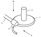
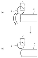
本発明の一実施形態としては、図1乃至図3に示した総型砥石の製造方法が挙げられる。ここで、図1は本発明の総型砥石の製造方法における、研削後の加工用砥石及びツルアーの斜視図であり、図2は本発明の総型砥石の製造方法を説明する図であって、加工用砥石の(a)研削前の状態、(b)研削後の状態を示した。ここで、図2は、図1の視点Aから見た砥石とツルアーの側断面図(砥石回転軸3の中心軸を通る直線の切断線による垂直断面図)を表わしている。また、図3は図2の研削工程における、ツルアーの工具軌跡を説明する図である。
(First embodiment)
As one embodiment of the present invention, there is a method for manufacturing a general-purpose grindstone shown in FIGS. Here, FIG. 1 is a perspective view of a grindstone for processing and a truer after grinding in a method for producing a general-purpose grindstone of the present invention, and FIG. 2 is a diagram for explaining a method for producing a general-purpose grindstone of the present invention. (A) State before grinding of processing grindstone, (b) State after grinding. Here, FIG. 2 represents a side cross-sectional view of the grindstone and the truer (vertical cross-sectional view taken along a straight cutting line passing through the central axis of the grindstone rotating shaft 3) viewed from the viewpoint A in FIG. FIG. 3 is a view for explaining the tool locus of the truer in the grinding step of FIG.
まず、総型砥石を製造する工程の概略を説明する。
最初に、総型砥石に加工される前の円板状の加工用砥石を用意する。そして、加工用砥石の縁部を、総型砥石形状に研削するが、その研削の際、図1に示したような配置で、加工用砥石の縁部に、ツルアー2を接触させながら移動させ、縁部を所望の形状に加工していく。図1に示した円板状砥石は、研削後の総型砥石1を示し、これは後述する図2(b)に相当する状態である。本発明に特徴的なのは研削工程におけるツルアーの動作である。
First, an outline of a process for producing a general-purpose grindstone will be described.
First, a disk-shaped processing grindstone before being processed into a total-type grindstone is prepared. Then, the edge of the processing grindstone is ground to the shape of the total grindstone. At the time of the grinding, in the arrangement as shown in FIG. 1, the
以下、より具体的に、本発明の総型砥石の製造方法の各工程を説明する。
まず、本発明の総型砥石の製造方法では、加工用砥石11は円板状であり、その円板の中心を研削加工機の砥石回転軸3に取り付けて固定し、水平回転させる(図2(a))。このとき、水平回転の回転速度は、通常、6〜12m/sである。また、ここで用いられる加工用砥石11の砥粒としては、ダイヤモンド、立方晶窒化ホウ素等の公知の砥粒が用いられ、結合材としてはレジノイド、ビトリファイド、メタル等の公知の結合材が用いられる。
Hereinafter, each process of the manufacturing method of the total type grindstone of this invention is demonstrated more concretely.
First, in the method for producing a general-purpose grindstone according to the present invention, the
次に、この水平回転している加工用砥石11の縁部に、円柱状のツルアー2を接触させて研削を行う(図1及び図2(b))。このとき、ツルアー2もその円柱状の底面がツルアー回転軸4に固定されて軸回転されており、さらに、ツルアー2を加工形状に合わせて上下に往復移動させることで研削する。このツルアー2の軸回転の回転速度は、通常、0.2〜0.8m/sである。ここで用いられるツルアー2の種類は、GC(グリーンカーボン)砥石、ビトリファイドダイヤモンド砥石、単石ダイヤモンドツルアー、軟鋼材等の公知のものが用いられる。
Next, grinding is performed by bringing the
このように水平回転している円板状の加工用砥石11の縁部を研削することで所望の加工形状(表面形状)を有する縁部へと加工をして総型砥石1とする。
By grinding the edge of the disk-
また、ツルアー2により加工用砥石11を研削する際、ツルアー2は加工用砥石1の縁部の加工形状に合わせて上下動を繰り返す往復運動により(図2(a)参照)、加工用砥石1の縁部の研削を漸次進めていき、所望の形状に近づけていく。例えば、加工用砥石11の縁部を図2(b)のように断面形状が円弧状となるように加工する場合には、ツルアー2の加工用砥石11との接触面が加工後の表面形状を描くように往復運動させる。なお、この方法自体は、従来の総型砥石の製造方法と変わるものではない。
In addition, when the
ところで、この往復運動をさせる際に描く工具軌跡は、従来法では、研削前のツルアーの表面が研削後の砥石の表面形状を描くように、研削後の加工形状に対して、研削前のツルアーの半径(r)だけ離間した軌跡となるようにしていた。ところが、このようにして研削を進めていくと、加工用砥石11だけではなく、ツルアー2の表面も摩耗するため、研削が終了した後のツルアー2の半径(r´)は、研削前よりも小さくなってしまっていた(r>r´;図2)。その摩耗によって、砥石の加工形状が所望の形状とは異なるものとなってしまい、改めて修正研削をする必要が生じ、効率的な製造方法とは言えなかった。
By the way, in the conventional method, the tool trajectory to be drawn when performing the reciprocating motion is such that the surface of the tooler before grinding describes the surface shape of the grindstone after grinding with respect to the processed shape after grinding. The trajectory is separated by a radius (r). However, when the grinding proceeds in this way, not only the
そこで、本発明においては、上記の研削時の上下に往復運動させる際の工具軌跡を、ツルアー2の研削前の状態から算出するのではなく、ツルアー2が加工用砥石11を研削した後のツルアー2の形状から算出するものとした。すなわち、予め、ツルアー2の研削後の摩耗状態を考慮に入れて、ツルアー2の動きを制御するものである。
Therefore, in the present invention, the tool trajectory at the time of reciprocating up and down at the time of grinding is not calculated from the state before grinding of the
なお、このツルアー2の摩耗状態を把握するために、本発明の総型砥石の製造方法を行うにあたっては、事前に、同一の加工用砥石11及びツルアー2を使用した従来法による総型砥石の研削を行う(工具軌跡を研削前のツルアーの半径rだけ離間させたものとする)。
In order to grasp the wear state of the truer 2, in carrying out the method for producing the general-purpose grindstone of the present invention, the conventional grindstone according to the conventional method using the
そして、研削後のツルアー半径(r´)は、その研削した後のツルアーの摩耗量(w)を調べ、研削前のツルアー半径と摩耗量とから算出(r´=r−w)、又は直接加工した後のツルアーの半径を測定、により決定すればよい。 Then, the grounder radius (r ′) after grinding is calculated from the truer radius and the amount of wear before grinding (r ′ = r−w) by examining the wearer (w) after grinding. The radius of the truer after processing may be determined by measurement.
このようにして決定した本発明のツルアー2の工具軌跡は、図3にその説明図を示した。なお、本明細書でいう工具軌跡とは、ツルアー2の中心軸2aが描く軌跡を意味する。
The tool locus of the truer 2 of the present invention determined in this way is shown in FIG. In addition, the tool locus as used in this specification means the locus which the
図3は図2(a)と同一の視点から見た研削前の状態を示した図である。加工用砥石11の輪郭は実線で、研削後の表面形状は破線で示した。また、ツルアー2の中心軸2aは、一点鎖線で示したように、研削後の加工形状に、研削後のツルアー2の半径r´だけ離間した軌跡を描くようにする。
FIG. 3 is a view showing a state before grinding as seen from the same viewpoint as FIG. The contour of the
このような工具軌跡にして研削を進めていくと、研削終了直前には、ツルアー2の表面が摩耗しており、その摩耗した表面が描く軌跡は、目的としている総型砥石の表面形状とほぼ一致し、得られる表面形状は目的の形状との誤差が極めて小さく、修正加工を要しないものとなる。 When grinding is carried out with such a tool trajectory, the surface of the truer 2 is worn immediately before the end of grinding, and the trajectory drawn by the worn surface is substantially the same as the surface shape of the target grindstone. The surface shape thus obtained has a very small error from the target shape and does not require correction processing.
なお、実際の研削の始まりは、ツルアー2を加工用砥石11に接しないように(図3で言えば左側に)十分に離れた距離から、上記説明した工具軌跡(一点鎖線)を描きながら徐々に加工用砥石11に近づけていき、研削を開始する。最初は、加工用砥石11の上部と下部がツルアー2と接触し、削られていき、所定の上下往復回数に従い、ツルアー2を加工用砥石11の中心に向けて前進させながら、ツルアー2と加工用砥石11の接触部分を研削する。
It should be noted that the actual grinding is started gradually while drawing the above-described tool trajectory (dashed line) from a sufficient distance so that the truer 2 does not contact the processing grindstone 11 (on the left side in FIG. 3). Then, the grinding
加工用砥石11の縁部が全て研削されたときに、砥石が所定の加工形状となっているため、研削の終了とする。研削の終了は、予め十分な加工量となるようにツルアー2を前進させる距離を設定しておいて自動で動作させたり、縁部の側面を加工用砥石11とは異なる色で着色しておいて、その着色部分が全て研削により無くなったのを人が目視で判断して操作したり、すればよい。
When all the edges of the
なお、上記説明において、総型砥石の加工表面については、縁部の断面形状が円弧状とする場合を例示して説明したが、この円弧状には、円弧の他に、2次以上の多項式で表現される曲線の断面形状も含む。ここで、断面を円弧に加工した場合には、いわゆる球面レンズ用(後述するシリンドリカルレンズ又はトロイダルレンズ)の成形型を作成でき、断面を2次以上の多項式で表現される曲線の断面形状に加工した場合には、いわゆる非球面レンズ用(後述する非球面シリンドリカルレンズ又は非トロイダルレンズ)の成形型を作成できるものである。いずれの場合にも、予め摩耗量を調べた上で、加工後のツルアーの半径を算出又は測定し、加工後の表面形状(加工形状)に対して上記加工後のツルアーの半径だけ離間した工具軌跡を描くようにツルアーの動作を制御すればよい。 In the above description, the processing surface of the general-purpose grindstone has been described by exemplifying the case where the cross-sectional shape of the edge is an arc shape. The cross-sectional shape of the curve expressed by Here, when the cross section is processed into a circular arc, a so-called spherical lens (cylindrical lens or toroidal lens described later) mold can be created, and the cross section is processed into a curved cross-sectional shape expressed by a polynomial of second order or higher. In this case, a molding die for a so-called aspherical lens (aspherical cylindrical lens or non-toroidal lens described later) can be created. In any case, after checking the amount of wear in advance, the radius of the processed lure is calculated or measured, and the tool is separated from the post-processed surface shape (processed shape) by the radius of the processed truer. The operation of the truer may be controlled so as to draw a locus.
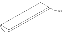
上記のようにして得られた総型砥石1は、例えば、レンズ用の成形型の加工に用いられる。図4に示したように、成形型に対して総型砥石1を水平回転させながら、矢印(破線)に従って成形型の表面に沿って移動させて加工を行い、加工を終えた後は矢印(点線)に従って退避動作を行わせることで、所望の形状に加工された成形型50が得られる。このように溝状態に形成された加工面によってレンズを成形すると、図5に示したシリンドリカルレンズ又は非球面シリンドリカルレンズと呼ばれる円柱形状を軸方向で切断した形状のレンズが得られる。
通常のシリンドリカルレンズの成形型の加工は、小半径の砥石を往復させて形状を加工していく。本総型砥石を用いることで往復回数を極端に少なくできる。
The
In the processing of a normal cylindrical lens mold, a shape is processed by reciprocating a small radius grindstone. The number of reciprocations can be extremely reduced by using this total type grindstone.
また、図4において、総型砥石1を成形型の表面に沿って移動させることなく、成形型加工面の中央に総型砥石1を垂直に押し込むように移動させて加工すると、総型砥石1の輪郭形状を反映した成形面が形成される。このような成形型からはトロイダルレンズ又は非トロイダルレンズと呼ばれるシリンドリカルレンズ又は非球面シリンドリカルレンズをさらに長軸方向に湾曲させた形状のレンズを成形するのに使用できる。
Further, in FIG. 4, if the
(第2の実施形態)
本実施形態は、第1の実施形態において、研削時のツルアー2の動作を改良した他の実施形態である。図6は、この実施形態を説明する図である。なお、図6は、図1の視点Bから見た平面図である。
(Second Embodiment)
This embodiment is another embodiment in which the operation of the truer 2 during grinding is improved in the first embodiment. FIG. 6 is a diagram for explaining this embodiment. FIG. 6 is a plan view seen from the viewpoint B in FIG.
第1の実施形態では、ツルアー2は、表面形状に合わせて上下に往復運動させるだけであったが、この実施形態では、さらに、左右の動きも加えて研削を行うものである。すなわち、図6に示したように、加工用砥石11の平面形状である円の接線方向(矢印方向)にツルアー2を水平移動させるものである。
In the first embodiment, the truer 2 is merely reciprocated up and down in accordance with the surface shape. However, in this embodiment, the left and right movements are also added to perform grinding. That is, as shown in FIG. 6, the truer 2 is moved horizontally in the tangential direction (arrow direction) of a circle which is a planar shape of the
第1の実施形態のように左右に固定した状態で研削を行うと、ツルアー2の加工用砥石11との接触部である中央が摩耗し易く、鞍状に湾曲した平面形状となってしまう場合がある。このようになると、場合によっては、点接触での研削ではなく面接触の研削となってしまい、面接触となった場合には、加工用砥石11を所望の形状に研削できなくなる場合がある。
When grinding is performed in a state of being fixed to the left and right as in the first embodiment, the center that is the contact portion with the
ところが、本実施形態のように左右方向にも往復運動させながら研削を行うと、ツルアー2の表面における摩耗が中央部のみに集中することなく均一に生じるため、総型砥石の形状誤差を抑制でき、研削操作時の不具合を生じることもない。 However, when grinding is performed while reciprocating in the left-right direction as in this embodiment, wear on the surface of the truer 2 occurs uniformly without concentrating only on the central portion, so that the shape error of the total-type grindstone can be suppressed. There is no problem during grinding operation.
このとき、左右への動きは、回数が多いほど好ましく、加工用砥石11の円板厚さをT、ツルアー2の半径をRt、左右への往復回数をnとした場合、往復回数nは下記式(1)を満たす範囲に設定するのが好ましい。

なお、本実施形態のように研削を行う場合には、事前のツルアーの摩耗量の算出においても同様に、加工用砥石11の平面形状である円の接線方向にツルアーを水平移動させて、同様の条件として算出することは言うまでもない。
When grinding is performed as in the present embodiment, similarly in the calculation of the previous wear amount of the truer, the truer is similarly moved by moving the truer in the tangential direction of the circle that is the planar shape of the
以下、本発明を実施例によりさらに詳細に説明する。 Hereinafter, the present invention will be described in more detail with reference to examples.
まず、本発明の総型砥石の製造方法を実施する前に、従来の方法によって総型砥石を加工し、その加工結果に基づいてツルアーの加工後の半径を算出し、算出された加工後の半径を用いて本発明の総型砥石の製造方法を実施した。以下、詳細に説明する。 First, before carrying out the manufacturing method of the total type grindstone of the present invention, the total type grindstone is processed by a conventional method, the radius after processing of the truer is calculated based on the processing result, Using the radius, the method for producing a general-purpose grindstone of the present invention was carried out. Details will be described below.
(実施例1)
[加工後のツルアー半径の算出]
加工用砥石として、直径40mm、厚さ7mmの円板状のレジンボンドダイヤモンド砥石を、ツルアーとして、直径8mm、長さ10mmの円筒形状のビトリファイドダイヤモンド砥石を準備した。なお、加工用砥石の縁部は断面が半径4mmの円となる形状である。
Example 1
[Calculation of Truer radius after processing]
A disk-shaped resin-bonded diamond grindstone having a diameter of 40 mm and a thickness of 7 mm was prepared as a processing grindstone, and a cylindrical vitrified diamond grindstone having a diameter of 8 mm and a length of 10 mm was prepared as a truer. The edge of the processing grindstone has a shape with a cross section of a circle having a radius of 4 mm.
このとき、目的とする総型砥石の縁部形状は、その断面が近似半径4mmの非球面形状であり、まずは、この目標形状に対して誤差10μm程度の粗加工を行った。次に、目的の垂直断面形状に対して、ツルアー半径だけ離間した軌跡を描くように上下動するツルアーの工具軌跡を設定し、さらに、図6で説明した上方から見た時に加工用砥石の接線方向に往復運動する動きも加えて、図1に示したようにツルアーを加工用砥石の縁部に接触させながらツルーイング(研削)を行い、総型砥石を製造した。 At this time, the edge shape of the target general-purpose grindstone was an aspherical shape with an approximate radius of 4 mm in cross section. First, rough machining with an error of about 10 μm was performed on the target shape. Next, a tool trajectory of the truer that moves up and down so as to draw a trajectory separated by the truer radius with respect to the target vertical cross-sectional shape is set, and the tangent line of the processing grindstone when viewed from above described with reference to FIG. In addition to the reciprocating movement in the direction, truing (grinding) was performed while the truer was in contact with the edge of the processing grindstone as shown in FIG.
なお、このとき、上下動1回するごとに、ツルアーを加工用砥石の中心側へ2μm移動させツルーイングし、このとき研削開始から研削終了までのツルーイング量は100μmであった。また、図6の接線方向への往復運動回数nは上下動1回あたり100回とした(上記式(1)で表わされる好ましいnの範囲は28≦n≦175である)。 At this time, each time the vertical movement was made, the truer was moved by 2 μm toward the center of the processing grindstone, and the truing amount from the start of grinding to the end of grinding was 100 μm. Further, the number of reciprocating motions n in the tangential direction in FIG. 6 was 100 per vertical movement (a preferable range of n represented by the above formula (1) is 28 ≦ n ≦ 175).
得られた総型砥石は、目標の加工形状に対して31μmの誤差が依然として残っており、このままでは製品とできず、さらに加工する必要があった。また、ツルアーの摩耗量をマイクロメータで測定したところ30μmであり、このときツルアーの半径は3.97mm(4mm−0.03mm)であった。 The obtained general-purpose grindstone still had an error of 31 μm with respect to the target machining shape, and as it was, it could not be made into a product and had to be further machined. The wear amount of the truer was measured with a micrometer and found to be 30 μm. At this time, the radius of the truer was 3.97 mm (4 mm−0.03 mm).
[本加工]
次に、上記と同一の加工用砥石及びツルアーを準備し、上記で決定した加工後のツルアーの半径を適用し、目的の断面形状に加工後のツルアー半径だけ離間した軌跡を描くように上下動するツルアーの工具軌跡を設定した以外は、上記ツルーイング方法と同様の操作によりツルーイングを行い、総型砥石を製造した。
[Main processing]
Next, prepare the same grinding wheel and truer for machining as above, apply the radius of the truer after machining as determined above, and move up and down to draw a trajectory separated by the truer radius after machining in the target cross-sectional shape Except that the tool trajectory of the truer to be set was set, truing was performed by the same operation as the above truing method to produce a total-type grindstone.
上記の操作により得られた総型砥石を用い、図4に示したように超硬合金製の成形型に非球面シリンドリカル形状の加工面が形成されるように加工を行った。成形型は直径40mm、厚さ10mmの円柱形状であり、非球面シリンドリカル形状の加工面は深さ1.6mmの凹形状で、短軸方向断面は非球面式であらわされる非球面形状である。成形型は事前に目標形状に対する誤差10μm程度に粗加工されており、加工前に砥石との接触判定用の着色を加工面に施した。図4の軌跡を2μmずつ金型と砥石の距離を接近させながら繰り返し、金型の着色が砥石により全て除去されたことを肉眼で確認できた時点で砥石形状が金型に転写されたと判断し、加工を終了した。 Using the grindstone obtained by the above operation, machining was performed so that a machining surface having an aspherical cylindrical shape was formed on a cemented carbide mold as shown in FIG. The mold has a cylindrical shape with a diameter of 40 mm and a thickness of 10 mm, the aspherical cylindrical processed surface has a concave shape with a depth of 1.6 mm, and the short-axis cross section has an aspherical shape represented by an aspherical type. The forming die was previously rough-processed to an error of about 10 μm with respect to the target shape, and the processing surface was colored for determining contact with the grindstone before processing. The trajectory of FIG. 4 is repeated by 2 μm while approaching the distance between the mold and the grindstone, and it is determined that the grindstone shape has been transferred to the mold when it is confirmed with the naked eye that all the coloration of the mold has been removed by the grindstone. Finished processing.
加工された金型の短軸方向の非球面形状について、設計値との誤差を3次元測定機UA3P(パナソニック株式会社製、商品名)にて調べた。設計値との誤差について得られた結果を図7に示した。ここで言う設計値の誤差とは、設計値から球面(曲率)成分を除いた誤差を示したものである。この結果から、目標形状に対する誤差は3.1μmであり、非球面シリンドリカル光学素子として十分な精度であることが確認できた。 Regarding the aspherical shape of the machined mold in the short axis direction, an error from the design value was examined with a three-dimensional measuring machine UA3P (manufactured by Panasonic Corporation, trade name). The results obtained with respect to the error from the design value are shown in FIG. The design value error here refers to an error obtained by removing the spherical (curvature) component from the design value. From this result, the error with respect to the target shape was 3.1 μm, and it was confirmed that the accuracy was sufficient as an aspheric cylindrical optical element.
本発明の総型砥石の製造方法は、総型砥石の製造に広く用いられ、特に、シリンドリカル(様)レンズ、トロイダル(様)レンズを成形する成形型加工用の総型砥石として有用である。 The method for producing a general-purpose grindstone of the present invention is widely used in the production of a general-purpose grindstone, and is particularly useful as a general-purpose grindstone for forming molds for forming cylindrical (like) lenses and toroidal (like) lenses.
1…総型砥石、1a…総型砥石ベース,1b…砥粒層、2…ツルアー、2a…中心軸、3…砥石回転軸、4…ツルアー回転軸、11…加工用砥石、50…成形型、51…シリンドリカルレンズ
DESCRIPTION OF
Claims (5)
前記研削工程において、前記ツルアーの工具軌跡を、前記総型砥石の加工形状に前記ツルアーの研削後の半径だけ離間した軌跡とすることを特徴とする総型砥石の製造方法。 While rotating the disk-shaped processing grindstone before chamfering the edge horizontally, a cylindrically held truer is chamfered on the edge of the processing grindstone so that the edge is chamfered in a circular arc shape. A method for producing a general-purpose grindstone having a grinding step in which it is moved while moving up and down and advanced toward the center of the processing grindstone,
In the grinding step, the tool trajectory of the truer is a trajectory separated from the processed shape of the general grindstone by a radius after grinding of the truer.
Priority Applications (1)
| Application Number | Priority Date | Filing Date | Title |
|---|---|---|---|
| JP2011060273A JP2012192510A (en) | 2011-03-18 | 2011-03-18 | Method for manufacturing total type grinding wheel |
Applications Claiming Priority (1)
| Application Number | Priority Date | Filing Date | Title |
|---|---|---|---|
| JP2011060273A JP2012192510A (en) | 2011-03-18 | 2011-03-18 | Method for manufacturing total type grinding wheel |
Publications (1)
| Publication Number | Publication Date |
|---|---|
| JP2012192510A true JP2012192510A (en) | 2012-10-11 |
Family
ID=47084914
Family Applications (1)
| Application Number | Title | Priority Date | Filing Date |
|---|---|---|---|
| JP2011060273A Withdrawn JP2012192510A (en) | 2011-03-18 | 2011-03-18 | Method for manufacturing total type grinding wheel |
Country Status (1)
| Country | Link |
|---|---|
| JP (1) | JP2012192510A (en) |
Cited By (2)
| Publication number | Priority date | Publication date | Assignee | Title |
|---|---|---|---|---|
| CN105081977A (en) * | 2015-07-10 | 2015-11-25 | 郑州磨料磨具磨削研究所有限公司 | Quick and efficient shaping method of super-abrasive grinding wheel |
| JP2016203342A (en) * | 2015-04-27 | 2016-12-08 | 株式会社Sumco | Truer manufacturing method, semiconductor wafer manufacturing method, and semiconductor wafer chamfering apparatus |
-
2011
- 2011-03-18 JP JP2011060273A patent/JP2012192510A/en not_active Withdrawn
Cited By (2)
| Publication number | Priority date | Publication date | Assignee | Title |
|---|---|---|---|---|
| JP2016203342A (en) * | 2015-04-27 | 2016-12-08 | 株式会社Sumco | Truer manufacturing method, semiconductor wafer manufacturing method, and semiconductor wafer chamfering apparatus |
| CN105081977A (en) * | 2015-07-10 | 2015-11-25 | 郑州磨料磨具磨削研究所有限公司 | Quick and efficient shaping method of super-abrasive grinding wheel |
Similar Documents
| Publication | Publication Date | Title |
|---|---|---|
| KR101600997B1 (en) | Polishing device for columnar member, columnar member and polishing method therefor | |
| CN104959667B (en) | Knife face band Unequal distance arc head milling cutter and method for grinding after a kind of eccentric shape | |
| CN110177650B (en) | Method and device for shaping a workpiece | |
| JP2009142979A (en) | Truing tool for grinding wheel and manufacturing method thereof, truing device using the same, manufacturing method of grinding wheel, and wafer edge grinding apparatus | |
| CN107297691B (en) | The Dressing Method of Composite Sectional Profile of Optical Machining Parallel Diamond Grinding Wheel | |
| JP5181703B2 (en) | Processing method of concave Fresnel lens shaped member and concave Fresnel lens shaped member | |
| JP5213442B2 (en) | Raster cutting technology for ophthalmic lenses | |
| JP7696865B2 (en) | Trueer molding method | |
| CN102869477A (en) | Autocalibration | |
| JP2009184066A5 (en) | ||
| JP2018524187A (en) | Grinding machine and method for machining a workpiece | |
| JP6378626B2 (en) | Optical element processing tool and optical element manufacturing method | |
| JP2016068231A (en) | Lens molding die processing apparatus and processing method, lens molding die and lens | |
| JP2012192510A (en) | Method for manufacturing total type grinding wheel | |
| JP5300939B2 (en) | Machining method using finishing tools | |
| US2329713A (en) | Lens edging device | |
| US5179931A (en) | Working gemstones | |
| JP3762248B2 (en) | Die processing method for diffractive optical element | |
| JP2017124460A (en) | Method and apparatus for continuously processing non-spherical shape of workpiece by cup shaped grind stone | |
| JP2008310202A (en) | Method for producing lens or lens precursor | |
| JP2010220714A (en) | Dental prosthesis production apparatus and method | |
| JP2006289566A (en) | Grinding processing method and grinding processing device of forming die of micro lens array | |
| JP4374161B2 (en) | Cutting method of optical lens or its mold | |
| JPS591555B2 (en) | rotary diamond dresser | |
| JP2012111663A (en) | Metal mold for molding optical device, method for molding optical device, and method for manufacturing metal mold for molding optical device |
Legal Events
| Date | Code | Title | Description |
|---|---|---|---|
| A300 | Withdrawal of application because of no request for examination |
Free format text: JAPANESE INTERMEDIATE CODE: A300 Effective date: 20140603 |