JP2012192532A - Resin molding method and resin molding apparatus - Google Patents
Resin molding method and resin molding apparatus Download PDFInfo
- Publication number
- JP2012192532A JP2012192532A JP2011056118A JP2011056118A JP2012192532A JP 2012192532 A JP2012192532 A JP 2012192532A JP 2011056118 A JP2011056118 A JP 2011056118A JP 2011056118 A JP2011056118 A JP 2011056118A JP 2012192532 A JP2012192532 A JP 2012192532A
- Authority
- JP
- Japan
- Prior art keywords
- resin
- cavity
- molding
- molding cavity
- mold
- Prior art date
- Legal status (The legal status is an assumption and is not a legal conclusion. Google has not performed a legal analysis and makes no representation as to the accuracy of the status listed.)
- Granted
Links
Images




Landscapes
- Moulds For Moulding Plastics Or The Like (AREA)
- Injection Moulding Of Plastics Or The Like (AREA)
Abstract
【課題】成形品の成形品質を向上する。
【解決手段】成形キャビティ11と、成形キャビティ11の周囲に設けられるオーバーフローキャビティ12と、成形キャビティ11とオーバーフローキャビティ12との間に設けられ、エアベント18が形成された境界部13とを有する金型2を用いる。まず、金型2でワークWをクランプして成形キャビティ11へ樹脂を圧送し、オーバーフローキャビティ12への流出を境界部13で抑止しながら、成形キャビティ11内へ樹脂25を充填する。次いで、所定の樹脂圧より高く樹脂圧を上昇させ、成形キャビティ11からエアベント18を介してオーバーフローキャビティ12へ樹脂25を流出させる。次いで、成形キャビティ11内で充填されている樹脂25を加熱硬化させる。
【選択図】図4[PROBLEMS] To improve the molding quality of a molded product.
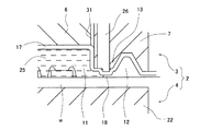
A mold having a molding cavity, an overflow cavity provided around the molding cavity, and a boundary portion provided between the molding cavity and the overflow cavity and having an air vent formed therein. 2 is used. First, the workpiece W is clamped by the mold 2 and the resin is pumped to the molding cavity 11, and the resin 25 is filled into the molding cavity 11 while the outflow to the overflow cavity 12 is suppressed by the boundary portion 13. Next, the resin pressure is raised higher than a predetermined resin pressure, and the resin 25 flows out from the molding cavity 11 to the overflow cavity 12 through the air vent 18. Next, the resin 25 filled in the molding cavity 11 is cured by heating.
[Selection] Figure 4
Description
本発明は、樹脂モールド方法および樹脂モールド装置に適用して有効な技術に関する。 The present invention relates to a technique effective when applied to a resin molding method and a resin molding apparatus.
半導体チップ等を樹脂モールドする樹脂モールド装置では、キャビティ内のエアを排出するためのエアベントが設けられている。通常、エアベントは、ゲートが形成されたキャビティ側部と対向する(反対側の)キャビティ側部のクランプ面にエアベント溝を形成し、樹脂注入時にこのエアベント溝を通じてキャビティ内のエアを外部に排出するようにしている。エアベントは、エアを排出する一方、流動性が高い樹脂においてはエアベント溝から樹脂が漏れ出し易いという課題を有している。そのため、エアベント溝にエアベントピンを設け、エアは排出するが樹脂は漏れ出させないためのエアベント機構を設ける場合がある。 In a resin molding apparatus that resin molds a semiconductor chip or the like, an air vent for discharging air in the cavity is provided. Normally, an air vent forms an air vent groove on the clamp surface of the cavity side (opposite side) opposite to the cavity side where the gate is formed, and discharges the air in the cavity to the outside through the air vent groove when resin is injected. I am doing so. The air vent discharges air, while the resin having high fluidity has a problem that the resin easily leaks from the air vent groove. Therefore, an air vent pin is provided in the air vent groove, and an air vent mechanism for discharging air but preventing resin from leaking out may be provided.
例えば、特開2009−292076号公報(特許文献1)には、トランスファ成形において、可動ピンをエアベントの流路内に設けて金型を閉じた後プランジャにより樹脂流頭がエアベントの直前位置に到達するまでエアを排出させ、到達した際に可動ピンをエアベント内に進出させてエアベントを閉じた(閉塞)状態にさせ、キャビティ内への溶融樹脂の充填を100%にして加熱硬化することにより樹脂モールド成形を行う技術が開示されている(明細書段落[0030]、[0031]参照)。 For example, in Japanese Patent Application Laid-Open No. 2009-292076 (Patent Document 1), in transfer molding, a movable pin is provided in a flow path of an air vent and a mold is closed, and then a resin flow head reaches a position immediately before the air vent by a plunger. The air is discharged until it reaches, and when it reaches, the movable pin is advanced into the air vent so that the air vent is closed (closed), and the resin is heated and cured with 100% filling of the molten resin in the cavity. A technique for molding is disclosed (see paragraphs [0030] and [0031] of the specification).
このような可動ピン(エアベントピン)は、トランスファ成形に限らず圧縮成形にも適用される。例えば、特開2010−36515号公報(特許文献2)には、クランパに設けられたエアベントピンを用いて、型閉じ完了直前までエアベント溝を開けておき、型締めと共にエアベント溝を完全に閉止してキャビティを完全に密閉状態とし、キャビティ内に樹脂を圧縮した状態で熱硬化させることによって圧縮成形を完了させる技術が開示されている(明細書段落[0021]参照)。 Such a movable pin (air vent pin) is applied not only to transfer molding but also to compression molding. For example, in Japanese Patent Application Laid-Open No. 2010-36515 (Patent Document 2), an air vent pin provided in a clamper is used to open an air vent groove until just before mold closing, and the air vent groove is completely closed together with mold clamping. Thus, a technique is disclosed in which the cavity is completely sealed and compression molding is completed by thermosetting the resin in a compressed state (see paragraph [0021] of the specification).
これらの特許文献1、2の技術は、エアベントから樹脂が漏れ出てしまうという不具合を防止するためのものである。なお、特許文献1の可動ピン、特許文献2のエアベントピンとは機能が異なる調圧ピンが、特開2010−173083号公報(特許文献3)に開示されている。
These techniques of
この特許文献3には、樹脂充填工程において、成形キャビティと連通する過剰樹脂収容部が配設されているため、該成形キャビティ内に流入した溶融樹脂材料の一部がこの過剰樹脂収容部内にも流入させる技術が開示されている(明細書段落[0018]参照)。また、薄型樹脂パッケージの成形工程において、キャビティブロックの降下作用に基づく樹脂加圧力によって薄型樹脂パッケージの厚みを成形するためのキャビティ容量を超える溶融樹脂材料の過剰分を、過剰樹脂収容部内に流入させる技術が開示されている(明細書段落[0019]参照)。この樹脂成形品は、過剰樹脂収容部に設けられた調圧ピンの弾性押圧力によって離型される(明細書段落[0020]参照)。
In this
例えば、トランスファ成形の場合、上型と下型からなる金型によりワークをクランプし、キャビティ内に樹脂を充填して樹脂モールドを行う際、成形品の厚さが例えば0.3mm程度に薄くなると、溶融した封止樹脂の硬化が促進され易いため、樹脂の流動可能な範囲が限定されてしまう。例えば、キャビティの底部と、ワーク上の例えば半導体素子の上面との隙間が狭い場合、封止樹脂が充填され難いことや、樹脂中のフィラーが偏在してしまうことなどが起きやすくなる。 For example, in the case of transfer molding, when a workpiece is clamped by a mold composed of an upper mold and a lower mold, and resin molding is performed by filling a resin in the cavity, the thickness of the molded product becomes as thin as about 0.3 mm, for example. Since the melting of the molten sealing resin is easily promoted, the range in which the resin can flow is limited. For example, when the gap between the bottom of the cavity and the upper surface of the semiconductor element, for example, on the workpiece is narrow, it is difficult to fill the sealing resin or the filler in the resin is unevenly distributed.
そこで、成形品の厚さ寸法より所定厚だけキャビティの底部を深く(後退)させて良好な樹脂の流動を確保し、キャビティへ樹脂を充填した後、キャビティの深さを成形品の厚さ寸法になるまで、当該キャビティ内の余剰樹脂を押し出す技術が開発されている(特開2009−190400号公報)。しかしながら、この技術により製造された成形品において、その表面にフローマーク(模様)が発生してしまうものが見受けられた。フローマークが発生した成形品は、品質が劣り、製造歩留まりを低下させてしまう。 Therefore, the bottom of the cavity is deepened (retracted) by a predetermined thickness from the thickness of the molded product to ensure good resin flow, and after filling the cavity with the resin, the cavity depth is set to the thickness of the molded product. Until then, a technique for extruding excess resin in the cavity has been developed (Japanese Patent Laid-Open No. 2009-190400). However, in the molded product manufactured by this technique, a flow mark (pattern) is observed on the surface. The molded product in which the flow mark is generated is inferior in quality and decreases the manufacturing yield.
本発明の目的は、成形品の成形品質を向上することのできる技術を提供することにある。本発明の前記ならびにその他の目的と新規な特徴は、本明細書の記述および添付図面から明らかになるであろう。 An object of the present invention is to provide a technique capable of improving the molding quality of a molded product. The above and other objects and novel features of the present invention will be apparent from the description of this specification and the accompanying drawings.
本願において開示される発明のうち、代表的なものの概要を簡単に説明すれば、次のとおりである。本発明の一実施形態における樹脂モールド方法は、成形キャビティと、前記成形キャビティの周囲に設けられるオーバーフローキャビティと、前記成形キャビティと前記オーバーフローキャビティとの間に設けられ、エアベントが形成された境界部とを有する金型を用いる樹脂モールド方法であって、(a)前記金型でワークをクランプして前記成形キャビティへ樹脂を圧送し、前記オーバーフローキャビティへの流出を前記境界部で抑止しながら、前記成形キャビティ内へ樹脂を充填する工程と、(b)前記(a)工程後、所定の樹脂圧より高く樹脂圧を上昇させ、前記成形キャビティから前記エアベントを介して前記オーバーフローキャビティへ樹脂を流出させる工程と、(c)前記(b)工程後、前記成形キャビティ内で充填されている樹脂を加熱硬化させる工程と、を含む。 Of the inventions disclosed in the present application, the outline of typical ones will be briefly described as follows. A resin molding method according to an embodiment of the present invention includes a molding cavity, an overflow cavity provided around the molding cavity, a boundary portion provided between the molding cavity and the overflow cavity, and an air vent formed therein. A resin molding method using a mold having the following: (a) clamping a workpiece with the mold and pumping resin to the molding cavity, while suppressing outflow to the overflow cavity at the boundary portion, A step of filling the molding cavity with resin; and (b) after the step (a), the resin pressure is raised higher than a predetermined resin pressure, and the resin flows out from the molding cavity to the overflow cavity via the air vent. And (c) after the step (b), the mold cavity is filled. Comprising a step of heating and curing the resin.
本願において開示される発明のうち、代表的なものによって得られる効果を簡単に説明すれば、次のとおりである。成形品の成形品質を向上することができる。 Of the inventions disclosed in the present application, effects obtained by typical ones will be briefly described as follows. The molding quality of the molded product can be improved.
以下、本発明の実施形態を図面に基づいて詳細に説明する。なお、実施形態を説明するための全図において、同一の機能を有する部材には同一の符号を付し、その繰り返しの説明は省略する場合がある。 Hereinafter, embodiments of the present invention will be described in detail with reference to the drawings. Note that components having the same function are denoted by the same reference symbols throughout the drawings for describing the embodiments, and the repetitive description thereof may be omitted.
(実施形態1)
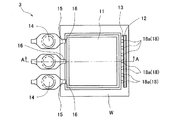
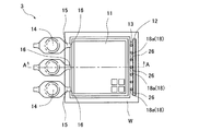
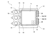
本発明の実施形態1を、図1〜図8を参照して説明する。樹脂モールド装置1Aでは、金型2の中央部に設けられたカル14を対称に成形キャビティ11が配置されるが、説明を明解にするために、図1などでは、片側の成形キャビティ11を省略している。また、図5〜図8では、金型2の構成箇所に対応して形成されたワークWの箇所に、金型2の構成箇所の符号を付して説明を明解にしている。
(Embodiment 1)
A first embodiment of the present invention will be described with reference to FIGS. In the
樹脂モールド装置1Aの概略構成について図1および図5を参照して説明する。図1の断面図は、図5の矢印A−A線に対応している。
A schematic configuration of the
この樹脂モールド装置1Aでは、図示しない被成形品供給部からローダにより被成形品(ワークW)が金型2を備えたプレス部に搬入(供給)され、樹脂モールドされた後、アンローダにより成形品(ワークW)がプレス部から取り出されて成形品収納部へ収納される。この金型2は、互いに対向して配置される上型3と下型4で構成される。樹脂モールド装置1Aでは、下型4に載置されたワークWに対して、上型3と下型4とでクランプ(すなわち、金型2でクランプ)して樹脂モールドを行うものである。なお、図1に示すワークWは、配線基板上に複数の半導体チップが搭載されたものである。
In this
金型2は、クランプ(クランパ)の高さ位置によって容積が可変する成形キャビティ11と、成形キャビティ11の周囲に設けられるオーバーフローキャビティ12とを有している。成形キャビティ11は、上型3のクランプ面で開口する凹部形状となっており、下型4にワークが載置され、下型4と共にワークをクランプ及び型締めされて内部空間ができる。この成形キャビティ11の内部空間でワークWの半導体チップが樹脂によってモールド(封止)される。また、オーバーフローキャビティ12は、上型3のクランプ面で開口する凹部形状となっており、成形キャビティ11から流出した余剰樹脂が収容される。
The
また、成形キャビティ11とオーバーフローキャビティ12とは、金型2の境界部13によってわずかに連通している。図5に示すように、本実施形態では、オーバーフローキャビティ12は、金型2でクランプされるワークWの内側に設けられている。
Further, the
金型2の上型3では、上型ベースブロック5が図示しない固定プラテンに固定して組み付けられている。また、一枚の凹部状の上型チェイスブロック10が底部側で上型ベースブロック5に固定して組み付けられている。この上型チェイスブロック10外側下部には、上型ストッパブロック8が取り付けられている。また、上型ベースブロック5には、上型チェイスブロック10内に搭載され、上型チェイスブロック10に貫通させた孔に上型キャビティブロック6が固定して組み付けられている。
In the
この上型キャビティブロック6は、成形キャビティ11の底部を形成するものであり、図1に示すように、外形の異なる多段のブロックが積層されてなる。このブロックが多段となり形成された凹部(上型キャビティブロック6の外周側)に、上型可動クランパブロック7(以下、上型可動クランパ7という)が抜け止めされて組み付けられている。これら上型キャビティブロック6および上型可動クランパ7は、凹部状の上型チェイスブロック10の内側に組み付けられている。
The upper
上型可動クランパ7は、上型チェイスブロック10の貫通孔に設けられたスプリング9(バネともいう)を介して上型ベースブロック5と弾発するように摺動自在かつ抜け止めされて嵌め込まれている。また、上型可動クランパ7には、上型キャビティブロック6を挿入する貫通孔が成形キャビティ11に合わせて複数箇所設けられている。このため、上型キャビティブロック6の周囲に上型可動クランパ7が配置されることになり、成形キャビティ11の底部が上型キャビティブロック6により、側部が上型可動クランパ7により形成される。
The upper mold
上型可動クランパ7の中央部には、成形キャビティ11へ連通するカル14、ランナ15、ゲート16が順に設けられている。ゲート16は、成形キャビティ11の側部に設けられている。このため、ゲート16を通じて、成形キャビティ11の側部から樹脂が流入することとなる(図5参照)。
A
上型可動クランパ7のクランプ面外周側には、オーバーフローキャビティ12が設けられている。オーバーフローキャビティ12は、ゲート16側と反対側の成形キャビティ11の側部に境界部13を介して設けられている。図5に示すように、このオーバーフローキャビティ12は、成形キャビティ11の側部に沿う方向に延びて設けられている。
An
オーバーフローキャビティ12は、成形キャビティ11から流出した樹脂25(余剰樹脂)を受け入れて収容するものである。成形キャビティ11へ流入した樹脂25の流頭側には、フローマークの原因となるフィラーが樹脂25中から押し出されて偏在する場合がある。そこで、オーバーフローキャビティ12を設け、フィラーが偏在するような場合を考慮し、余剰樹脂を成形キャビティ11からオーバーフローキャビティ12に流出させている。
The
また、上型可動クランパ7の境界部13には、成形キャビティ11とオーバーフローキャビティ12とを連通する複数の溝18aによってエアベント18が形成されている(図5参照)。成形キャビティ11から流出した樹脂は、エアベント18を介してオーバーフローキャビティ12へ流入するため、溝18aの溝深さ、溝幅、溝長さ、溝の面性状、数によって、その流入量を調整することができる。
In addition, an
また、上型可動クランパ7は、弾性部材であるスプリング9を介して上型ベースブロック5に組み付けられ、下型4に載置されたワークWに当接するものである。図1に示す状態では、上型可動クランパ7は、スプリング9を介して吊り下げ支持(フローティング支持)されている。成形キャビティ11を形成する上型可動クランパ7は、上下動することで、相対的に成形キャビティ11の深さを可変、すなわち成形キャビティ11の容積を可変できる。
The upper mold
上型ストッパブロック8は、上型可動クランパ7の周囲に配置され、上型チェイスブロック10を介して上型ベースブロック5に固定して組み付けられている。図1に示すように、上型ストッパブロック8は、上型3の外側に位置している。また、上型ストッパブロック8は、下型4に当接するものである。上型ストッパブロック8は、上型可動クランパ7のように弾性部材を介するものではなく、上型ベースブロック5に固定して組み付けられているため、下型4に当接するまで、上型3と下型4は近接する。また、上型ストッパブロック8と上型チェイスブロック10の間に調整駒を設けることによって、上型3と下型4との距離の調整を容易に行うことができる。
The upper
本実施形態では、成形キャビティ11を含む上型3のクランプ面には、クランプ面を覆うリリースフィルム17が張設される。リリースフィルム17は上型面にブロック間の隙間を利用した吸引機構により吸着保持されるようになっている。リリースフィルム17は、例えば長尺状のフィルム材が用いられ、ロール状に巻き取られた繰出しロールから引き出されて上型クランプ面を通過して巻取りロールへ巻き取られるように設けられる。
In the present embodiment, a
下型4は、下型チェイスブロック21、下型インサートブロック22およびポット23を含んで構成されている。この下型4は、図示しない可動プラテンに組み付けられている。具体的には、下型インサートブロック22は、下型チェイスブロック21と図示しない下型ベースブロックを介して可動プラテンに組み付けられている。
The
下型チェイスブロック21には、図1に示すように、縁部から一段凹んだ凹部が形成されている。この凹部には、下型インサートブロック22が嵌め込まれる。また、下型チェイスブロック21の縁部は、下型4の外側に位置しており、上型3の上型ストッパブロック8と当接する。すなわち、上型3と下型4は、上型ストッパブロック8と下型チェイスブロック21の縁部とが当接する状態まで近接する。
As shown in FIG. 1, the
下型インサートブロック22は、下型チェイスブロック21の凹部に嵌め込むように組み付けられている。下型インサートブロック22の上面にはワークWが載置されるワーク載置部が設けられている。
The lower
下型チェイスブロック21と下型インサートブロック22の中央部には、ポット23を挿入するために、貫通孔が複数箇所に設けられている。ポット23内には公知のトランスファ駆動機構により上下動するプランジャ24が設けられている。プランジャ24は、複数のポット23に対応して複数本が支持ブロックに設けられるマルチプランジャが用いられる。このプランジャ24は、図5に示す複数のカル14のそれぞれに対向して複数設けられる。
In the central part of the lower
以下に、ワークWに対して、樹脂モールド装置1Aを用いた樹脂モールド方法について図1〜図4を参照して説明する。なお、一例として、ワークWの成形品の厚さは基板面から0.3mmとして説明する。 Hereinafter, a resin molding method using the resin molding apparatus 1 </ b> A for the workpiece W will be described with reference to FIGS. 1 to 4. As an example, the thickness of the molded product of the workpiece W will be described as 0.3 mm from the substrate surface.
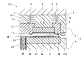
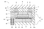
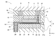
まず、図1に示すように、金型2が型開きした状態で搬入されたワークWを、下型4の下型インサートブロック22に載置する。また、上型3のクランプ面にはリリースフィルム17を吸着して、下型4のポット23には樹脂25(樹脂タブレット)を供給する。続いて、上型3と下型4を近接させて型締めを開始し、図2に示すように、上型可動クランパ7はリリースフィルム17を介してワークWに当接して、上型3と下型4とでワークWをクランプする。また、これにより、ワークWにはスプリング9の抵抗力(付勢力)にバランスされた所定のクランプ力(例えば、5〜10ton)が加わる。
First, as shown in FIG. 1, the workpiece W loaded with the
このときワークWは、上型3の上型キャビティブロック6が成形品の厚さ寸法(例えば0.3mm)より所定厚(例えば0.2mm)だけ後退した退避位置を保ったまま上型可動クランパ7によりクランプされる。なお、上型ストッパブロック8は、下型チェイスブロック21と所定間隔(0.2mm)開けて停止している。
At this time, the workpiece W has an upper mold movable clamper while maintaining a retracted position in which the
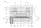
続いて、図3に示すように、金型2でワークWをクランプして所定のクランプ力(例えば、5〜10ton)を加えたまま、溶融した樹脂25を成形キャビティ11へ圧送し、オーバーフローキャビティ12への流出を境界部13で抑止しながら、所定の樹脂圧で成形キャビティ11内を充填する。この充填は、成形品の厚さ寸法より所定厚(例えば0.2mm)だけ成形キャビティ11の底部を深くした状態で行われる。本実施形態では、図示しないトランスファ駆動機構を作動させてプランジャ24を上昇させてカル14、ランナ15、ゲート16を通じて成形キャビティ11内へ溶融した樹脂25を充填して、樹脂圧を所定の第1保圧(例えば、1〜3MPa)として所定時間維持する。
Subsequently, as shown in FIG. 3, the workpiece W is clamped by the
このとき、上型3の上型キャビティブロック6が成形品の厚さ寸法より所定厚だけ後退した退避位置を保っているため、ワークWの上面と上型キャビティブロック6の底面との隙間が広がり、溶融した樹脂25をワークWの上面へ充填し易くすることができる。
At this time, since the
溶融した樹脂25を圧送することによって、成形キャビティ11内のエアが境界部13で形成されているエアベント18を介して排出される。また、境界部13では、成形キャビティ11内を樹脂25で充填する際に、エアが排出され、かつ、樹脂25の流出が抑止されるように、複数の溝18aが所定の溝深さ、溝幅、溝長さ、溝の面性状、数に形成されている。このとき、一定の樹脂圧で所定時間保持をすることにより、第1保圧が行われる。
By feeding the
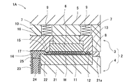
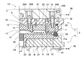
続いて、所定の樹脂圧(第1保圧)より高く樹脂圧を上昇させ、成形キャビティ11からエアベント18を介してオーバーフローキャビティ12へ樹脂を流出させる。具体的には、図4に示すように、下型4を更に上昇させ、上型可動クランパ7がスプリング9を押し縮めて、上型ベースブロック5側でキャビティ底部を形成する上型キャビティブロック6と略面一になると上型ストッパブロック8と下型チェイスブロック21が突き当たり、上昇が止まる。このとき、第1保圧より樹脂圧が上昇(8〜12MPa)し、成形キャビティ11の境界部13に形成されたエアベント溝18aで流出が抑止されていた樹脂25は、その限界を超えオーバーフローキャビティ12へ流入する。
Subsequently, the resin pressure is raised higher than a predetermined resin pressure (first holding pressure), and the resin flows out from the
本実施形態では、樹脂の粒状、樹脂圧などを考慮して、溝18aの溝深さ、溝幅、溝長さ、溝の面性状、数を調整している。また、図5に示すように、オーバーフローキャビティ12側へ開くような形状(テーパ形状)で溝18aを設けている。これにより、樹脂モールドし、硬化させることで、成形キャビティ11で形成された樹脂と、オーバーフローキャビティ12で形成された廃棄用の樹脂とを容易に分離できるようになる。
In the present embodiment, the groove depth, groove width, groove length, groove surface property, and number of the
本実施形態では、成形キャビティ11の底部を広げ、樹脂充填後、成形品の厚さ寸法になるまで成形キャビティの底部を押し下げる(浅くする)ことによって、フィラーが偏在している恐れのある樹脂25をオーバーフローキャビティ12へ流出させることができる。したがって、成形品にフローマークが発生するのを防止し、成形品質を向上することができる。
In this embodiment, the bottom of the
また、成形キャビティ11への樹脂25の充填時では、特にゲート16側と反対側の成形キャビティ11の側部にフィラーが偏在している恐れが高いため、本実施形態では、オーバーフローキャビティ12を、ゲート16側と反対側の成形キャビティ11の側部に境界部13を介して設けることにより、フィラーが偏在している恐れの高い樹脂25を効率的にオーバーフローキャビティ12へ流出させている。
In addition, when filling the
なお、下型が上昇することにより上型キャビティブロック6が成形品の厚さ寸法(例えば0.3mm)に対応する成形位置まで押し出されることで、オーバーフローキャビティ12に入りきれない成形キャビティ11の樹脂25がゲート16を介してポット23側にも押し戻される。このとき、プランジャ24が樹脂圧により後退させられて、余剰樹脂をポットに戻すことができる。
Note that the resin of the
このように、上型可動クランパ7がワークWをクランプした後、更なる型閉め動作により上型キャビティブロック6を成形キャビティ11へ相対的に押し出すことで、狙い通りの成形品の厚さ寸法(例えば0.3mm)にすることができる。
As described above, after the upper mold
続いて、成形キャビティ11内に充填されている樹脂25を加熱硬化することで、ワークWが樹脂モールドされる。具体的には、溶融した樹脂25を成形キャビティ11へ圧送し、第1保圧(例えば、1〜3MPa)の樹脂圧より大きい樹脂圧を所定の第2保圧(例えば、8〜12MPa)を維持して、所定時間加熱硬化する。これにより、パッケージの厚さ寸法が極めて薄い成形品を、新規な設備を用いることなく狙い通りの厚さ寸法で安価に量産することができる。
Subsequently, the
その後は、上型可動クランパ7がワークWをクランプしたまま下型4を僅かに(例えば0.2mm)下動させて上型キャビティブロック6のみを退避位置へ移動させることにより成形品を離型させる。下型4を更に下動させて型開きを行なうと、上型可動クランパ7がワークWより離間型開きした後、ワークWが下型4より取り出され、必要に応じて下型面がクリーニングされて1回分の成形動作が終了する。
Thereafter, the upper mold
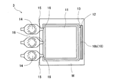
本実施形態では、図5に示したように、ゲート16側と反対側の成形キャビティ11の側部に、境界部13を介してオーバーフローキャビティ12を設けた場合について説明したが、図6に示すように、ゲート16が設けられた側部を除いた成形キャビティ11の他の側部に、境界部13を介してオーバーフローキャビティ12が設けられても良い。具体的には、図6に示すように、成形キャビティ11は平面視矩形状であるため、ゲート16が設けられた1つの側部を除いた3つの側部のそれぞれに、境界部13を介してオーバーフローキャビティ12が設けられている。
In the present embodiment, as shown in FIG. 5, the case where the
成形キャビティ11への樹脂25の充填時では、ゲート16側と反対側の側部の他にもフィラーが偏在する場合がある。そこで、ゲート16が設けられた側部を除いた成形キャビティ11の他の側部に、境界部13を介してオーバーフローキャビティ12を設けている。これにより、成形キャビティ11の側部でフィラーが偏在している樹脂25をオーバーフローキャビティ12へ流出させることができる。したがって、成形品にフローマークが発生するのを防止し、より成形品質を向上することができる。
At the time of filling the
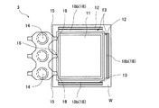
また、図5、図6では、成形キャビティ11とオーバーフローキャビティ12とを連通する複数の溝18aによってエアベント18を形成した場合について説明したが、図7、図8に示すように、境界部13には、成形キャビティ11に沿った長手および成形キャビティ11とオーバーフローキャビティ12とを連通する短手からなる幅狭な長溝18bによってエアベント18が形成されても良い。
5 and 6, the case where the
このように、成形キャビティ11に沿った長溝18bを設けることでも、成形キャビティ11の側部でフィラーが偏在している樹脂25(不要樹脂)を成形キャビティ11内に残存させることを防止することができる。したがって、成形品にフローマークが発生するのを防止し、より成形品質を向上することができる。また、長溝18bを設けることで、一度に、フィラーが偏在している樹脂25を、成形キャビティ11からオーバーフローキャビティ12へ効率よく流出させることができる。
Thus, even by providing the
(実施形態2)
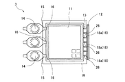
本発明の実施形態2を、図9〜図16を参照して説明する。樹脂モールド装置1Bでは、金型2の中央部に設けられたカル14を対称に成形キャビティ11が配置されるが、説明を明解にするために、図9などでは、片側の成形キャビティ11を省略している。また、図10、図14〜図16では、金型2の構成箇所に対応して形成されたワークWの箇所に、金型2の構成箇所の符号を付して説明を明解にしている。
(Embodiment 2)
A second embodiment of the present invention will be described with reference to FIGS. In the
図9の状態は、図4を参照して説明したように、下型チェイスブロック21にストッパブロック8を当接させ、成形キャビティ11の底部を押し下げて容積を小さくすると共に、オーバーフローキャビティ12へ樹脂25を流出させた状態である。また、図9の断面図は、図10の矢印A−A線に対応するものである。
9, as described with reference to FIG. 4, the
樹脂モールド装置1Bでは、上型可動クランパ7の境界部13に、成形キャビティ11とオーバーフローキャビティ12とを連通する複数の溝18aによってエアベント18が形成されている(図10参照)。また、エアベント18を形成する複数の溝18aに対してそれぞれを堰止めるように上下動可能な複数の可動ピン26が、境界部13に設けられている。具体的には、溝18aを貫通する貫通孔に可動ピン26が挿入されて堰止められるようになっている。また、可動ピン26は、スプリング27に連結して設けられている。
In the
前記実施形態1では、エアベントの溝18aが所定の溝深さ、溝幅、溝長さ、溝の面性状、数にする必要があり、樹脂によっては最適解を出すのが難しい場合があるため、もっと簡単に同様の効果を出す必要がある。そこで本実施形態2では溝18aを樹脂に影響され難い機構として、可動ピン26およびそれを上下動可能とするスプリング27を設ける機構とした。成形キャビティ11へ溶融した樹脂25を圧送し、オーバーフローキャビティ12への流出を境界部13で抑止しながら成形キャビティ11内を充填する際に、可動ピン26はスプリング27によって境界部13から突出するように付勢される。
In the first embodiment, the
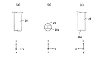
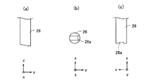
この可動ピン26の先端は、オーバーフローキャビティ12側に対して成形キャビティ11側が下がる形状であり、例えば、図11(a)に示すような段付き形状、図12(a)に示すようなテーパ形状としている。また、図11(b)、(c)、図12(b)、(c)に示すように、可動ピン26の先端面には溝26aが形成されている。なお、溝26aは、エアベント18を形成するものである。
The tip of the
可動ピン26は、その先端をオーバーフローキャビティ12側に対して成形キャビティ11側が下がる形状とすることで、エアベント18を介してオーバーフローキャビティ12へ樹脂25を流出させる際に、その樹脂25が可動ピン26の先端に潜り込むことによって、スプリング27の付勢力に抗して押し上げられる。また、可動ピン26の先端をテーパ形状として面取りした場合、樹脂25が可動ピン26を押し上げる際に、リリースフィルム17が破れるのを防止することができる。
The
このように、可動ピン26およびそれを上下動可能とするスプリング27を設けることでも、成形キャビティ11内へ樹脂25を充填する際に、オーバーフローキャビティ12への流出を抑止し、また、成形キャビティ11の底部を押し下げる際に、オーバーフローキャビティ12へ樹脂25を流出させることができる。すなわち、成形キャビティ11の底部を押し下げることによって、フィラーが偏在している樹脂25をオーバーフローキャビティ12へ流出させることができる。したがって、成形品にフローマークが発生するのを防止し、成形品質を向上することができる。
In this way, the provision of the
また、図9を参照してスプリング27を設けた場合について説明したが、図13に示すように、可動ピン26にアクチュエータ28を連結して、可動ピン26を上下動可能としても良い。アクチュエータ28を設けることで、可動ピン26の移動量及び突出タイミングを制御することができ、境界部13での樹脂25の抑止や、エアベント18を介する樹脂25の流出を容易に制御することができる。
Although the case where the
また、図10を参照して可動ピン26を設けた場合について説明したが、図14に示すように、長溝18bに対して堰止めるように上下動可能な可動板29(シャッタ)を境界部13に設けても良い。この可動板29の先端は、図11および図12に示したようなオーバーフローキャビティ12側に対して成形キャビティ11側が下がる形状である。このように、長溝18bに対して板状の可動板29を用いることで、一度にフィラーが偏在する余剰樹脂をオーバーフローキャビティ12へ流出させることができる。
Further, the case where the
また、成形キャビティ11の側部に沿う方向に延びる1つのオーバーフローキャビティ12(図10参照)を、図14に示すように、分割して設けても良い。これにより、オーバーフローキャビティ12内の樹脂25が加熱硬化後にシュリンクしたとき、ワークWに反りが発生するのを防止することができる。また、図15および図16に示すように、オーバーフローキャビティ12を、金型2でクランプされるワークWの外側に設けることで、よりワークWに反りが発生するのを防止することができる。
Further, one overflow cavity 12 (see FIG. 10) extending in the direction along the side of the
(実施形態3)
本発明の実施形態3を、図17〜図21を参照して説明する。樹脂モールド装置1Cでは、金型2の中央部に設けられたカル14を対称に成形キャビティ11が配置されるが、説明を明解にするために、図17などでは、片側の成形キャビティ11を省略している。
(Embodiment 3)
A third embodiment of the present invention will be described with reference to FIGS. In the
樹脂モールド装置1Cの金型2は、成形キャビティ11が形成された上型3とワークWが載置される下型4を主体として構成されている。この上型3において、上型キャビティブロック6と上型可動クランパ7との間、および、上型キャビティブロック6と上型可動クランパ7の中央部7aとの間、には上型3の表面に沿ってリリースフィルム17を吸引するためのフィルム吸引部31が設けられている。また、上型可動クランパ7と上型チェイスブロック32との間部分には気密用のシール部材33が設けられている。
The
上型チェイスブロック32には、上型キャビティブロック6が直接固定されている。上型チェイスブロック32とこれが固定された上型ベースブロック5との間には、弾発材であるコイルスプリング34A、35Aが弾装された支持部材34B、35Bが設けられている。上型可動クランパ7および上型センターブロック7aは、支持部材34B、35Bに支持されて上型チェイスブロック32から離間した状態で取り付けられている。リリースフィルム17は、フィルム吸引部31に連通するフィルム吸引手段36により上型3の成形キャビティ11を覆うようにして表面に吸着保持される。
The upper
境界部13には、ポット23、成形キャビティ11、オーバーフローキャビティ12などのエアをクランプ時に樹脂モールド装置1Cの外部(金型の外部)に排出するためのエアベント18が形成されている。エアベント18は、上型可動クランパ7に貫通状態で設けられた可動ピン26をクランプ面から突出させるように前進(進出)させることによって閉塞されると共に、クランプ面側から後退(退避)させることによって開放される。
The
この可動ピン26は、上型チェイスブロック32とこれが固定された上型ベースブロック5との間に弾装されたコイル状のスプリング27によって下方に付勢されている。また、可動ピン26は、図10に示したように、エアベント18を閉塞するために、溝18aの幅寸法よりも大きな径寸法に形成され、クランプ面におけるエアベント18上に上型可動クランパ7の支持方向(図17内の上下方向)に進退出可能に設けられている。また、この可動ピン26の先端は、図11(a)に示したような段付き形状である。
The
これにより、可動ピン26は、図17に示すように、スプリング27によって境界部13から突出するように付勢されている。この可動ピン26によって、成形キャビティ11へ溶融した樹脂25を圧送し、オーバーフローキャビティ12への流出を境界部13で抑止しながら成形キャビティ11内を充填することができる。
Thereby, the
樹脂モールド装置1Cにおいてエアベント18の平面位置よりもさらに外方側位置には、上型3と下型4とを型閉じ(クランプ)した際に、金型クランプ面を気密にシールするためのシール部材38が設けられている。エアベント18とシール部材38との間において下型4のクランプ面には、エアベント18から排出されたエアを流通させるためのエア流通路41が設けられている。このエア流通路41は、外部と遮断された成形キャビティ11内を、オーバーフローキャビティ12を介して減圧するエア給排装置42(減圧機構)に連通している。
In the
以下に、ワークWに対して、樹脂モールド装置1Cを用いた樹脂モールド方法について、一例として、ワークWの成形品の厚さは基板面から0.3mmとして説明する。
Hereinafter, the resin molding method using the
まず、金型2が型開きした状態で搬入されたワークWを、下型4の下型インサートブロック22に載置する。また、上型3のクランプ面にはリリースフィルム17を吸着する。また、ポット23に樹脂25(樹脂タブレット)を供給する。続いて、図17に示すように、上型3と下型4を近接させて型締めし、上型3と下型4とでワークWをクランプする。このときワークWは、上型3の上型キャビティブロック6が成形品の厚さ寸法(例えば0.3mm)より所定厚(例えば0.2mm)だけ後退した退避位置を保ったまま上型可動クランパ7によりクランプされる。
First, the work W carried in with the
続いて、エア給排装置42による減圧作用によって、ポット23、成形キャビティ11、オーバーフローキャビティ12などの間のエアを排出させると共に樹脂25に含まれている溶剤等の揮発成分と空気、水分等を予め樹脂モールド装置1Cの外部に排出する。これにより、その後に成形キャビティ11内に注送される樹脂25の中に含まれる気泡量を少なくすることができ、成形品質を向上することができる。
Subsequently, the air between the
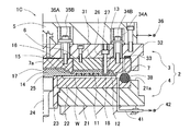
続いて、図18、図20に示すように、金型2でワークWをクランプして所定のクランプ力(例えば、5〜10ton)を加えたまま、溶融した樹脂25を成形キャビティ11へ圧送し、オーバーフローキャビティ12への流出を境界部13で抑止しながら所定の樹脂圧(第1保圧)を維持して成形キャビティ11内を充填する。具体的には、エア給排装置42によるエアの吸引動作は継続したまま、プランジャ24を上昇させてカル14、ランナ15、ゲート16を通じて成形キャビティ11内へ溶融した樹脂25を充填する。充填後樹脂圧を所定の第1保圧(例えば、1〜3MPa)として所定時間維持する。この際、図20に示すように、樹脂25は、境界部13の可動ピン26で抑止されている。
Subsequently, as shown in FIGS. 18 and 20, the workpiece W is clamped by the
図17、図18および図20に示すような工程において、上型可動クランパ7でクランプの際、ワークWから可動ピン26の先端部までの高さ(ギャップ)は、スプリング27によって境界部13から突出し、エアを排出するが、樹脂25は流出できない高さとなっている。本実施形態では、エア給排装置42(減圧機構)によってエアを吸引することで、樹脂25を流出しないように可動ピン26の先端部とワークWとのギャップを狭めたとしても、エアを排出することができる。
In the process shown in FIGS. 17, 18, and 20, the height (gap) from the workpiece W to the tip of the
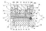
続いて、所定の樹脂圧(第1保圧)より高く樹脂圧を上昇させ、成形キャビティ11からエアベント18を介してオーバーフローキャビティ12へ樹脂を流出させる。具体的には、図19に示すように、下型4を更に上昇させ、上型可動クランパ7がコイルスプリング34A、35Aを押し縮めて、上型ベースブロック5側でキャビティ底部を形成する上型キャビティブロック6と略面一になると上昇が止まる。
Subsequently, the resin pressure is raised higher than a predetermined resin pressure (first holding pressure), and the resin flows out from the
このとき、第1保圧より樹脂圧が上昇(8〜12MPa)し、成形キャビティ11の境界部13に形成されたエアベント溝18aで流出が抑止されていた樹脂25は、その限界を超えオーバーフローキャビティ12へ流入する。すなわち、上型キャビティブロック6を、成形品の厚さ寸法(例えば0.3mm)に対応する成形位置までさらに押し出す。
At this time, the resin pressure rises (8 to 12 MPa) from the first holding pressure, and the
続いて、成形キャビティ11内で充填されている樹脂25を加熱硬化し、ワークWに対して樹脂モールドする。これにより、パッケージの厚さ寸法が極めて薄い成形品を、新規な設備を用いることなく狙い通りの厚さ寸法で安価に量産することができる。また、減圧機構を設けることによって、成形キャビティ11への樹脂25の充填の際にエアの排出を効率的に行うことができる。また、成形キャビティ11の底部を押し下げることによって、フィラーが偏在している樹脂25をオーバーフローキャビティ12へ流出させることができる。したがって、成形品にフローマークが発生するのを防止し、成形品質を向上することができる。
Subsequently, the
また、本実施形態では、図17を参照してスプリング27を設けた場合について説明したが、図21に示すように、リング状のパッキン43に通された中継ピン44を介して、図示しないアクチュエータからのエア押圧力と、スプリング45の抵抗力とによって、可動ピン26を上下動可能としても良い。アクチュエータを設けることで、可動ピン26の移動量を制御することができ、境界部13での樹脂25の抑止や、エアベント18を介する樹脂25の流出を容易に制御することができる。したがって、成形品にフローマークが発生するのを防止し、成形品質を向上することができる。
In the present embodiment, the case where the
以上、本発明を実施形態に基づき具体的に説明したが、本発明は前記実施形態に限定されるものではなく、その要旨を逸脱しない範囲で種々変更可能であることはいうまでもない。 Although the present invention has been specifically described above based on the embodiments, it is needless to say that the present invention is not limited to the above-described embodiments, and various modifications can be made without departing from the scope of the invention.
前記実施形態では、固定した上型キャビティブロック6およびこれに対して可動する可動クランパ7を組み付け、クランプ(可動クランパ7のクランパ面)の高さによって容積が可変する成形キャビティを有する金型に適用した場合について説明した。これに限らず、例えば、クランパブロックを固定し、これに対して可動するキャビティブロックを組み付け、アクチュエータなどによってキャビティブロックを可動させて容積が可変する成形キャビティを有する金型に適用しても良い。
In the above embodiment, the fixed upper
また、前記実施形態では、上型3に成形キャビティ11およびオーバーフローキャビティ12を設けた場合について説明した。これに限らず、上型3と下型4の構成を逆にして、例えば、成形キャビティおよびオーバーフローキャビティを下型に設けても良い。
In the embodiment, the case where the
1A、1B 樹脂モールド装置
2 金型
3 上型
4 下型
11 成形キャビティ
12 オーバーフローキャビティ
13 境界部
18 エアベント
25 樹脂
W ワーク
1A, 1B
Claims (8)
(a)前記金型でワークをクランプして前記成形キャビティへ樹脂を圧送し、前記オーバーフローキャビティへの流出を前記境界部で抑止しながら、前記成形キャビティ内へ樹脂を充填する工程と、
(b)前記(a)工程後、所定の樹脂圧より高く樹脂圧を上昇させ、前記成形キャビティから前記エアベントを介して前記オーバーフローキャビティへ樹脂を流出させる工程と、
(c)前記(b)工程後、前記成形キャビティ内で充填されている樹脂を加熱硬化させる工程と、
を含むことを特徴とする樹脂モールド方法。 A resin molding method using a mold having a molding cavity, an overflow cavity provided around the molding cavity, and a boundary portion provided between the molding cavity and the overflow cavity and formed with an air vent. ,
(A) clamping the workpiece with the mold and pumping the resin into the molding cavity, and filling the molding cavity with the resin while suppressing the outflow to the overflow cavity at the boundary;
(B) after the step (a), increasing the resin pressure higher than a predetermined resin pressure, and flowing the resin from the molding cavity to the overflow cavity via the air vent;
(C) After the step (b), a step of heat curing the resin filled in the molding cavity;
A resin molding method comprising:
前記(a)工程では、成形品の厚さ寸法より前記成形キャビティの底部を深くした状態で、前記成形キャビティ内へ樹脂が充填され、
前記(b)工程では、成形品の厚さ寸法になるまで前記成形キャビティの底部を浅くして、前記オーバーフローキャビティへ樹脂が流出することを特徴とする樹脂モールド方法。 The resin molding method according to claim 1,
In the step (a), resin is filled into the molding cavity in a state where the bottom of the molding cavity is deeper than the thickness dimension of the molded product,
In the step (b), the bottom of the molding cavity is shallowed until the thickness of the molded product is reached, and the resin flows out into the overflow cavity.
前記金型でワークをクランプして前記成形キャビティへ樹脂を圧送し、前記オーバーフローキャビティへの流出を前記境界部で抑止しながら前記成形キャビティ内へ樹脂を充填した後、所定の樹脂圧より高く樹脂圧を上昇させ、前記成形キャビティから前記エアベントを介して前記オーバーフローキャビティへ樹脂を流出させて、前記成形キャビティ内で充填されている樹脂を加熱硬化させることを特徴とする樹脂モールド装置。 A mold having a molding cavity, an overflow cavity provided around the molding cavity, and a boundary portion provided between the molding cavity and the overflow cavity and formed with an air vent;
The workpiece is clamped with the mold, the resin is pumped to the molding cavity, the resin is filled into the molding cavity while suppressing the outflow to the overflow cavity at the boundary, and then the resin is higher than a predetermined resin pressure. A resin molding apparatus, wherein pressure is increased, resin is flown out from the molding cavity to the overflow cavity through the air vent, and the resin filled in the molding cavity is heated and cured.
前記成形キャビティの側部には、樹脂が流入してくるゲートが設けられ、
前記ゲート側と反対側の前記成形キャビティの側部には、前記境界部を介して前記オーバーフローキャビティが設けられ、
前記境界部には、前記成形キャビティと前記オーバーフローキャビティとを連通する複数の溝によって前記エアベントが形成されていることを特徴とする樹脂モールド装置。 In the resin mold device according to claim 3,
The side of the molding cavity is provided with a gate into which resin flows,
On the side of the molding cavity opposite to the gate side, the overflow cavity is provided via the boundary,
The resin mold apparatus, wherein the air vent is formed in the boundary portion by a plurality of grooves communicating the molding cavity and the overflow cavity.
前記成形キャビティの側部には、樹脂が流入してくるゲートが設けられ、
前記ゲートが設けられた側部を除いた前記成形キャビティの他の側部には、前記境界部を介して前記オーバーフローキャビティが設けられ、
前記境界部には、前記成形キャビティと前記オーバーフローキャビティとを連通する複数の溝によって前記エアベントが形成されていることを特徴とする樹脂モールド装置。 In the resin mold device according to claim 3,
The side of the molding cavity is provided with a gate into which resin flows,
On the other side part of the molding cavity excluding the side part on which the gate is provided, the overflow cavity is provided via the boundary part,
The resin mold apparatus, wherein the air vent is formed in the boundary portion by a plurality of grooves communicating the molding cavity and the overflow cavity.
前記複数の溝に対してそれぞれを堰止めるように上下動可能な複数の可動ピンが、前記境界部に設けられていることを特徴とする樹脂モールド装置。 In the resin mold apparatus of Claim 4 or 5,
A resin mold apparatus, wherein a plurality of movable pins that can move up and down so as to dam each of the plurality of grooves are provided at the boundary portion.
前記可動ピンは、スプリングに連結して設けられ、前記スプリングによって前記境界部から突出するように付勢されており、前記エアベントを介して前記オーバーフローキャビティへ樹脂を流出させる際に前記成形キャビティからの樹脂圧によって上動されることを特徴とする樹脂モールド装置。 In the resin mold device according to claim 6,
The movable pin is connected to a spring and is urged by the spring so as to protrude from the boundary portion. When the resin flows out to the overflow cavity via the air vent, the movable pin is moved from the molding cavity. A resin molding apparatus characterized by being moved up by resin pressure.
前記可動ピンは、アクチュエータに連結して設けられ、前記アクチュエータによって前記境界部から突出するように下動されており、前記エアベントを介して前記オーバーフローキャビティへ樹脂を流出させる際に前記アクチュエータによって上動されることを特徴とする樹脂モールド装置。 In the resin mold device according to claim 6,
The movable pin is connected to an actuator and is moved downward by the actuator so as to protrude from the boundary portion. When the resin flows out into the overflow cavity via the air vent, the movable pin is moved upward by the actuator. Resin mold apparatus characterized by being made.
Priority Applications (1)
| Application Number | Priority Date | Filing Date | Title |
|---|---|---|---|
| JP2011056118A JP5776094B2 (en) | 2011-03-15 | 2011-03-15 | Resin molding method and resin molding apparatus |
Applications Claiming Priority (1)
| Application Number | Priority Date | Filing Date | Title |
|---|---|---|---|
| JP2011056118A JP5776094B2 (en) | 2011-03-15 | 2011-03-15 | Resin molding method and resin molding apparatus |
Publications (2)
| Publication Number | Publication Date |
|---|---|
| JP2012192532A true JP2012192532A (en) | 2012-10-11 |
| JP5776094B2 JP5776094B2 (en) | 2015-09-09 |
Family
ID=47084931
Family Applications (1)
| Application Number | Title | Priority Date | Filing Date |
|---|---|---|---|
| JP2011056118A Active JP5776094B2 (en) | 2011-03-15 | 2011-03-15 | Resin molding method and resin molding apparatus |
Country Status (1)
| Country | Link |
|---|---|
| JP (1) | JP5776094B2 (en) |
Cited By (16)
| Publication number | Priority date | Publication date | Assignee | Title |
|---|---|---|---|---|
| CN103645080A (en) * | 2013-12-09 | 2014-03-19 | 中国人民解放军63983部队 | Mold for preparing coaxial transmission and emission method test sample and method for preparing coaxial transmission and emission method test sample |
| WO2014136509A1 (en) * | 2013-03-08 | 2014-09-12 | アピックヤマダ株式会社 | Resin molding mold, resin molding device, resin molding method, and resin molding mold evaluation method |
| JP2014218038A (en) * | 2013-05-09 | 2014-11-20 | アピックヤマダ株式会社 | Resin mold method and device |
| JP2015051557A (en) * | 2013-09-06 | 2015-03-19 | アピックヤマダ株式会社 | Mold, resin molding apparatus and resin molding method |
| JP2017052287A (en) * | 2016-12-06 | 2017-03-16 | アピックヤマダ株式会社 | Resin molding device, resin molding method, and resin molding die |
| JP2017056739A (en) * | 2016-12-15 | 2017-03-23 | アピックヤマダ株式会社 | Resin mold and resin mold apparatus |
| KR20170095211A (en) * | 2014-12-15 | 2017-08-22 | 베시 네덜란드 비.브이. | Mould, moulding apparatus and method for controlled overmoulding of a carrier with electronic components and moulded product |
| JP2017159630A (en) * | 2016-03-11 | 2017-09-14 | 東芝メモリ株式会社 | Mold |
| JP2018014412A (en) * | 2016-07-21 | 2018-01-25 | アピックヤマダ株式会社 | Resin molding equipment |
| KR101838773B1 (en) * | 2014-07-31 | 2018-03-14 | 세메스 주식회사 | Apparatus for molding semiconductor devices |
| JP2019005902A (en) * | 2017-06-20 | 2019-01-17 | アピックヤマダ株式会社 | Mold and resin molding method |
| TWI674960B (en) * | 2017-03-03 | 2019-10-21 | 日商東芝記憶體股份有限公司 | Mold |
| CN111836707A (en) * | 2018-08-23 | 2020-10-27 | 山田尖端科技株式会社 | Casting mold and resin molding apparatus including the same |
| JP2021037679A (en) * | 2019-09-02 | 2021-03-11 | 日本碍子株式会社 | Method for producing resin molded body |
| WO2021053879A1 (en) * | 2019-09-18 | 2021-03-25 | Towa株式会社 | Molding mold, resin molding device, and production method for resin molded article |
| WO2022097392A1 (en) * | 2020-11-04 | 2022-05-12 | Towa株式会社 | Resin molding device and production method for resin molded article |
Citations (4)
| Publication number | Priority date | Publication date | Assignee | Title |
|---|---|---|---|---|
| JPH07112453A (en) * | 1993-10-18 | 1995-05-02 | Apic Yamada Kk | Resin molding device |
| JP2004235530A (en) * | 2003-01-31 | 2004-08-19 | Tsukuba Seiko Co Ltd | Sealing and molding apparatus and manufacturing method of sealed molding body using the same |
| JP2010036515A (en) * | 2008-08-07 | 2010-02-18 | Apic Yamada Corp | Resin molding apparatus and resin molding method |
| JP2010212628A (en) * | 2009-03-12 | 2010-09-24 | Fujitsu Semiconductor Ltd | Method of manufacturing semiconductor device |
-
2011
- 2011-03-15 JP JP2011056118A patent/JP5776094B2/en active Active
Patent Citations (4)
| Publication number | Priority date | Publication date | Assignee | Title |
|---|---|---|---|---|
| JPH07112453A (en) * | 1993-10-18 | 1995-05-02 | Apic Yamada Kk | Resin molding device |
| JP2004235530A (en) * | 2003-01-31 | 2004-08-19 | Tsukuba Seiko Co Ltd | Sealing and molding apparatus and manufacturing method of sealed molding body using the same |
| JP2010036515A (en) * | 2008-08-07 | 2010-02-18 | Apic Yamada Corp | Resin molding apparatus and resin molding method |
| JP2010212628A (en) * | 2009-03-12 | 2010-09-24 | Fujitsu Semiconductor Ltd | Method of manufacturing semiconductor device |
Cited By (36)
| Publication number | Priority date | Publication date | Assignee | Title |
|---|---|---|---|---|
| KR102162395B1 (en) * | 2013-03-08 | 2020-10-06 | 아피쿠 야마다 가부시키가이샤 | Resin molding mold, resin molding device, resin molding method, and resin molding mold evaluation method |
| WO2014136509A1 (en) * | 2013-03-08 | 2014-09-12 | アピックヤマダ株式会社 | Resin molding mold, resin molding device, resin molding method, and resin molding mold evaluation method |
| JP2014172287A (en) * | 2013-03-08 | 2014-09-22 | Apic Yamada Corp | Resin molding mold, resin molding apparatus, resin molding method and method of evaluating resin molding mold |
| KR20150126360A (en) * | 2013-03-08 | 2015-11-11 | 아피쿠 야마다 가부시키가이샤 | Resin molding mold, resin molding device, resin molding method, and resin molding mold evaluation method |
| TWI634627B (en) * | 2013-03-08 | 2018-09-01 | 山田尖端科技股份有限公司 | Resin molding device, resin molding method, and resin molding die |
| JP2014218038A (en) * | 2013-05-09 | 2014-11-20 | アピックヤマダ株式会社 | Resin mold method and device |
| JP2015051557A (en) * | 2013-09-06 | 2015-03-19 | アピックヤマダ株式会社 | Mold, resin molding apparatus and resin molding method |
| CN103645080A (en) * | 2013-12-09 | 2014-03-19 | 中国人民解放军63983部队 | Mold for preparing coaxial transmission and emission method test sample and method for preparing coaxial transmission and emission method test sample |
| KR101838773B1 (en) * | 2014-07-31 | 2018-03-14 | 세메스 주식회사 | Apparatus for molding semiconductor devices |
| KR20170095211A (en) * | 2014-12-15 | 2017-08-22 | 베시 네덜란드 비.브이. | Mould, moulding apparatus and method for controlled overmoulding of a carrier with electronic components and moulded product |
| US10913191B2 (en) | 2014-12-15 | 2021-02-09 | Besi Netherlands B.V. | Mould, moulding apparatus and method for controlled overmoulding of a carrier with electronic components and moulded product |
| JP2017537821A (en) * | 2014-12-15 | 2017-12-21 | ベシ ネーデルランズ ビー.ヴイ.Besi Netherlands B.V. | Mold, molding apparatus and method for overmold control of carrier having electronic component, and molded product |
| KR102239452B1 (en) * | 2014-12-15 | 2021-04-15 | 베시 네덜란드 비.브이. | Mould, moulding apparatus and method for controlled overmoulding of a carrier with electronic components and moulded product |
| JP2017159630A (en) * | 2016-03-11 | 2017-09-14 | 東芝メモリ株式会社 | Mold |
| CN107180771B (en) * | 2016-03-11 | 2020-08-14 | 东芝存储器株式会社 | mold |
| CN107180771A (en) * | 2016-03-11 | 2017-09-19 | 东芝存储器株式会社 | Mould |
| JP2018014412A (en) * | 2016-07-21 | 2018-01-25 | アピックヤマダ株式会社 | Resin molding equipment |
| JP2017052287A (en) * | 2016-12-06 | 2017-03-16 | アピックヤマダ株式会社 | Resin molding device, resin molding method, and resin molding die |
| JP2017056739A (en) * | 2016-12-15 | 2017-03-23 | アピックヤマダ株式会社 | Resin mold and resin mold apparatus |
| TWI674960B (en) * | 2017-03-03 | 2019-10-21 | 日商東芝記憶體股份有限公司 | Mold |
| US10896825B2 (en) | 2017-03-03 | 2021-01-19 | Toshiba Memory Corporation | Mold |
| JP2019005902A (en) * | 2017-06-20 | 2019-01-17 | アピックヤマダ株式会社 | Mold and resin molding method |
| KR20200141089A (en) | 2018-08-23 | 2020-12-17 | 아피쿠 야마다 가부시키가이샤 | Molding mold and resin molding device equipped with it |
| CN111836707B (en) * | 2018-08-23 | 2022-04-26 | 山田尖端科技株式会社 | Casting mold and resin casting apparatus including the same |
| TWI797372B (en) * | 2018-08-23 | 2023-04-01 | 日商山田尖端科技股份有限公司 | Molding mold and resin molding device equipped with same |
| CN111836707A (en) * | 2018-08-23 | 2020-10-27 | 山田尖端科技株式会社 | Casting mold and resin molding apparatus including the same |
| JP2021037679A (en) * | 2019-09-02 | 2021-03-11 | 日本碍子株式会社 | Method for producing resin molded body |
| WO2021053879A1 (en) * | 2019-09-18 | 2021-03-25 | Towa株式会社 | Molding mold, resin molding device, and production method for resin molded article |
| KR20220006117A (en) * | 2019-09-18 | 2022-01-14 | 토와 가부시기가이샤 | Molding mold, resin molding apparatus and manufacturing method of resin molded article |
| JP2021045890A (en) * | 2019-09-18 | 2021-03-25 | Towa株式会社 | Molding die, resin molding apparatus and manufacturing method of resin molded product |
| KR102576139B1 (en) | 2019-09-18 | 2023-09-06 | 토와 가부시기가이샤 | Molding mold, resin molding device, and manufacturing method of resin molding |
| US11938660B2 (en) | 2019-09-18 | 2024-03-26 | Towa Corporation | Mold die, resin molding apparatus, and method for producing resin molded product |
| WO2022097392A1 (en) * | 2020-11-04 | 2022-05-12 | Towa株式会社 | Resin molding device and production method for resin molded article |
| JP2022074514A (en) * | 2020-11-04 | 2022-05-18 | Towa株式会社 | Resin molding device and manufacturing method of resin molded article |
| JP7360374B2 (en) | 2020-11-04 | 2023-10-12 | Towa株式会社 | Resin molding equipment and method for manufacturing resin molded products |
| US12194665B2 (en) | 2020-11-04 | 2025-01-14 | Towa Corporation | Resin molding apparatus and method for producing resin molded product |
Also Published As
| Publication number | Publication date |
|---|---|
| JP5776094B2 (en) | 2015-09-09 |
Similar Documents
| Publication | Publication Date | Title |
|---|---|---|
| JP5776094B2 (en) | Resin molding method and resin molding apparatus | |
| JP5824765B2 (en) | Resin molding method, resin molding apparatus, and supply handler | |
| JP5906528B2 (en) | Mold and resin molding apparatus using the same | |
| JP6491508B2 (en) | Resin sealing device and method of manufacturing resin molded product | |
| JP5352896B2 (en) | Transfer molding method and transfer molding apparatus | |
| TWI593538B (en) | Resin molding die and resin molding device | |
| KR101643451B1 (en) | Resin-sealing apparatus and resin-sealing method | |
| JP5854096B1 (en) | Resin sealing device | |
| JP5774545B2 (en) | Resin sealing molding equipment | |
| JP6020667B1 (en) | Transfer molding machine and method of manufacturing electronic component | |
| JP6137679B2 (en) | Resin molding apparatus and resin molding method | |
| JP5817044B2 (en) | Resin sealing device and resin sealing method | |
| CN112840441B (en) | Conveying device, resin molding device, conveying method, and method for manufacturing resin molded product | |
| CN113597365B (en) | Manufacturing method of resin molded products | |
| JP6804275B2 (en) | Molding mold, resin molding equipment and resin molding method | |
| JP5892683B2 (en) | Resin sealing method | |
| JP6111459B2 (en) | Resin molding method and resin molding apparatus | |
| TW201902650A (en) | Molding mold and resin molding method | |
| KR20190017684A (en) | Resin molding product transportation device, resin molding device and method for preparing resin molding product | |
| JP4426880B2 (en) | Resin sealing device and resin sealing method | |
| JP5776093B2 (en) | Resin sealing device | |
| JP5958505B2 (en) | Resin sealing device and sealing method thereof | |
| KR101052324B1 (en) | Encapsulant Forming Method | |
| US20240408802A1 (en) | Mold for resin molding, resin molding apparatus, and method for producing resin molded article | |
| JP6749167B2 (en) | Resin molding equipment |
Legal Events
| Date | Code | Title | Description |
|---|---|---|---|
| A621 | Written request for application examination |
Free format text: JAPANESE INTERMEDIATE CODE: A621 Effective date: 20131216 |
|
| A977 | Report on retrieval |
Free format text: JAPANESE INTERMEDIATE CODE: A971007 Effective date: 20141008 |
|
| A131 | Notification of reasons for refusal |
Free format text: JAPANESE INTERMEDIATE CODE: A131 Effective date: 20141014 |
|
| A521 | Request for written amendment filed |
Free format text: JAPANESE INTERMEDIATE CODE: A523 Effective date: 20141205 |
|
| TRDD | Decision of grant or rejection written | ||
| A01 | Written decision to grant a patent or to grant a registration (utility model) |
Free format text: JAPANESE INTERMEDIATE CODE: A01 Effective date: 20150609 |
|
| A61 | First payment of annual fees (during grant procedure) |
Free format text: JAPANESE INTERMEDIATE CODE: A61 Effective date: 20150615 |
|
| R150 | Certificate of patent or registration of utility model |
Ref document number: 5776094 Country of ref document: JP Free format text: JAPANESE INTERMEDIATE CODE: R150 |
|
| R250 | Receipt of annual fees |
Free format text: JAPANESE INTERMEDIATE CODE: R250 |
|
| R250 | Receipt of annual fees |
Free format text: JAPANESE INTERMEDIATE CODE: R250 |
|
| R250 | Receipt of annual fees |
Free format text: JAPANESE INTERMEDIATE CODE: R250 |
|
| R250 | Receipt of annual fees |
Free format text: JAPANESE INTERMEDIATE CODE: R250 |
|
| R250 | Receipt of annual fees |
Free format text: JAPANESE INTERMEDIATE CODE: R250 |
|
| S111 | Request for change of ownership or part of ownership |
Free format text: JAPANESE INTERMEDIATE CODE: R313111 |
|
| R350 | Written notification of registration of transfer |
Free format text: JAPANESE INTERMEDIATE CODE: R350 |