JP2012192568A - Displaying body and method for determining authenticity - Google Patents
Displaying body and method for determining authenticity Download PDFInfo
- Publication number
- JP2012192568A JP2012192568A JP2011057005A JP2011057005A JP2012192568A JP 2012192568 A JP2012192568 A JP 2012192568A JP 2011057005 A JP2011057005 A JP 2011057005A JP 2011057005 A JP2011057005 A JP 2011057005A JP 2012192568 A JP2012192568 A JP 2012192568A
- Authority
- JP
- Japan
- Prior art keywords
- interface portion
- display body
- display
- linear polarizer
- interface
- Prior art date
- Legal status (The legal status is an assumption and is not a legal conclusion. Google has not performed a legal analysis and makes no representation as to the accuracy of the status listed.)
- Withdrawn
Links
Images

Landscapes
- Credit Cards Or The Like (AREA)
- Polarising Elements (AREA)
- Diffracting Gratings Or Hologram Optical Elements (AREA)
- Inspection Of Paper Currency And Valuable Securities (AREA)
Abstract
【課題】偽造防止効果が高い表示体及び真偽判定方法を提供する。
【解決手段】本発明に係る表示体は、白色光で照明した際に指向性散乱光を射出するように構成された第1の複数の凹部又は凸部が設けられた第1界面部と、前記第1界面部と隣り合い、複屈折性を示すように構成された第2の複数の凹部又は凸部が設けられた第2界面部とを具備している。前記第1界面部が最大の光散乱能を示す第1方向と、前記第2界面部の遅相軸に平行な第2方向とは、互いに平行であるか又は互いに所定の角度で交わっている。
【選択図】図2Provided are a display body and an authenticity determination method having a high anti-counterfeit effect.
A display according to the present invention includes a first interface portion provided with a plurality of first concave portions or convex portions configured to emit directional scattered light when illuminated with white light, and And a second interface portion provided with a plurality of second concave portions or convex portions configured to be birefringent and adjacent to the first interface portion. The first direction in which the first interface portion exhibits the maximum light scattering ability and the second direction parallel to the slow axis of the second interface portion are parallel to each other or intersect at a predetermined angle. .
[Selection] Figure 2
Description
本発明は、表示体及び真偽判定方法に関する。 The present invention relates to a display body and a true / false determination method.
有価証券、証明書、ブランド品、電子機器及び個人認証媒体などの物品には、偽造が困難であることが望まれる。そのため、このような物品には、偽造防止効果に優れた表示体を支持させることがある。 It is desired that counterfeiting is difficult for articles such as securities, certificates, branded products, electronic devices, and personal authentication media. For this reason, such an article may support a display body having an excellent anti-counterfeit effect.
従来、偽造防止技術を施した表示体として、種々の構成が知られている(例えば、特許文献1乃至7参照)。また、偽造防止技術への適用は意図されていないが、近年では、構造性複屈折を利用した光学効果の研究も為されている(例えば、非特許文献1及び2参照)。 2. Description of the Related Art Conventionally, various configurations have been known as a display body that has been subjected to anti-counterfeit technology (see, for example, Patent Documents 1 to 7). In addition, although application to anti-counterfeiting technology is not intended, in recent years, studies on optical effects using structural birefringence have been made (for example, see Non-Patent Documents 1 and 2).
本発明の目的は、偽造防止効果が高い表示体及び真偽判定方法を提供することにある。 An object of the present invention is to provide a display body and a true / false determination method having a high anti-counterfeit effect.
本発明の第1側面によると、白色光で照明した際に指向性散乱光を射出するように構成された第1の複数の凹部又は凸部が設けられた第1界面部と、前記第1界面部と隣り合い、複屈折性を示すように構成された第2の複数の凹部又は凸部が設けられた第2界面部とを具備し、前記第1界面部が最大の光散乱能を示す第1方向と、前記第2界面部の遅相軸に平行な第2方向とは、互いに平行であるか又は互いに所定の角度で交わっている表示体が提供される。 According to the first aspect of the present invention, the first interface portion provided with a first plurality of concave portions or convex portions configured to emit directional scattered light when illuminated with white light, and the first A second interface portion provided with a plurality of second concave portions or convex portions that are adjacent to the interface portion and exhibit birefringence, and the first interface portion has the maximum light scattering ability. A display body is provided in which the first direction shown and the second direction parallel to the slow axis of the second interface portion are parallel to each other or intersect each other at a predetermined angle.
本発明の第2側面によると、第1側面に係る表示体の真偽判定方法であって、直線偏光子を介して前記表示体のうち少なくとも前記第2界面部に対応した部分を観察することを含んだ真偽判定方法が提供される。 According to the second aspect of the present invention, there is provided a method for determining the authenticity of a display body according to the first aspect, wherein at least a portion corresponding to the second interface portion of the display body is observed through a linear polarizer. A true / false determination method including the above is provided.
本発明によると、偽造防止効果が高い表示体及び真偽判定方法を提供することが可能となる。 ADVANTAGE OF THE INVENTION According to this invention, it becomes possible to provide the display body and authenticity determination method with a high forgery prevention effect.
以下、本発明の態様について、図面を参照しながら詳細に説明する。なお、同様又は類似した機能を発揮する構成要素には全ての図面を通じて同一の参照符号を付し、重複する説明は省略する。 Hereinafter, embodiments of the present invention will be described in detail with reference to the drawings. In addition, the same referential mark is attached | subjected to the component which exhibits the same or similar function through all the drawings, and the overlapping description is abbreviate | omitted.
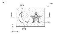
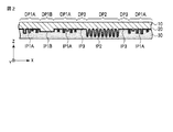
図1は、本発明の一態様に係る表示体の一例を示す平面図である。図2は、図1に示す表示体のII−II線に沿った断面図である。図1及び図2では、表示体100の主面に平行であり且つ互いに直交する方向をX方向及びY方向とし、表示体100の主面に垂直な方向をZ方向としている。
FIG. 1 is a plan view illustrating an example of a display body according to one embodiment of the present invention. 2 is a cross-sectional view taken along the line II-II of the display shown in FIG. 1 and 2, directions parallel to the main surface of the
図1及び図2に示す表示体100は、表示部DP1Aと、表示部DP1Bと、表示部DP2と、表示部DP3とを含んでいる。また、この表示体100は、レリーフ層10と、光反射性材料層20と、粘着層30とを含んでいる。図1及び図2には、一例として、レリーフ層10が光反射性材料層20に対して前面側に位置している場合を描いている。
The
レリーフ層10と光反射性材料層20との界面は、界面部IP1Aと、界面部IP1Bと、界面部IP2と、界面部IP3とを含んでいる。界面部IP1A、IP1B、IP2、及びIP3は、それぞれ、表示部DP1A、DP1B、DP2、及びDP3に対応している。
The interface between the
レリーフ層10の一方の主面には、複数の凹部又は凸部が設けられている。レリーフ層10の材料としては、例えば、可視光透過性を有する樹脂を使用することができる。特には、熱可塑性樹脂、熱硬化性樹脂又は光硬化性樹脂を使用すると、原版を用いた転写により、上記の複数の凹部又は凸部を容易に形成することができる。それゆえ、この場合、複数の凹部又は凸部を原版に高精度に形成しておけば、精密な量産複製品を比較的容易に製造することができる。
A plurality of concave portions or convex portions are provided on one main surface of the
レリーフ層10は、単層構造を有していてもよく、多層構造を有していてもよい。レリーフ層10は、樹脂への染料の添加などにより、着色されていてもよい。
The
光反射性材料層20は、レリーフ層10の複数の凹部又は凸部が設けられた主面の少なくとも一部を被覆している。この層を設けることにより、複数の凹部又は凸部に起因した光学効果をより顕著にすることができる。
The light
光反射性材料層20の材料としては、例えば、アルミニウム、銀及び金などの金属材料が挙げられる。或いは、光反射性材料層20の材料として、レリーフ層10とは屈折率が異なった誘電体からなる透明材料を用いてもよい。光反射性材料層20は、単層構造を有していてもよく、多層構造を有していてもよい。
Examples of the material of the light
光反射性材料層20は、例えば、蒸着及びスパッタリングなどの薄膜形成技術により形成することができる。また、光反射性材料層20の存在する領域を空間的に分布させることにより、この光反射性材料層20の分布を用いて、図柄を表現することもできる。
The light
粘着層30は、光反射性材料層20の背面側に設けられており、光反射性材料層20を間に挟んでレリーフ層10と向き合っている。粘着層30の材料としては、例えば、塩化ビニル−酢酸ビニル共重合体、ポリエステル系ポリアミド、及び、アクリル系、ブチルゴム系、天然ゴム系、シリコン系又はポリイソブチル系のものが挙げられる。
The
粘着層30は、例えば、グラビア印刷法、オフセット印刷法及びスクリーン印刷法などの印刷法、又は、バーコート法、グラビア法及びロールコート法などの塗布法により形成することができる。粘着層30は、単層構造を有していてもよく、多層構造を有していてもよい。粘着層30は、省略してもよい。
The
レリーフ層10と光反射性材料層20との界面は、上述した通り、界面部IP1A、IP1B、IP2、及びIP3を含んでいる。以下、これらの構成及び光学効果について説明する。
As described above, the interface between the
界面部IP1Aは、白色光で照明した際に指向性散乱光を射出するように構成された複数の凹部又は凸部を備えている。ここで「指向性散乱光」とは、観察方向によって光散乱能が異なる散乱光を意味している。ここで「光散乱能」とは、一定以上の強度の散乱光が射出される角度範囲の大きさを意味している。
以下では、界面部が最大の光散乱能を示す方向を「高散乱方向」と呼び、最小の光散乱能を示す方向を「低散乱方向」と呼ぶ。高散乱方向と低散乱方向とは、典型的には、互いに直交している。
The interface portion IP1A includes a plurality of concave portions or convex portions configured to emit directional scattered light when illuminated with white light. Here, “directional scattered light” means scattered light having different light scattering capabilities depending on the observation direction. Here, the “light scattering ability” means the size of an angle range in which scattered light having a certain intensity or more is emitted.
Hereinafter, the direction in which the interface portion exhibits the maximum light scattering ability is referred to as “high scattering direction”, and the direction in which the minimum light scattering ability is indicated is referred to as “low scattering direction”. The high scattering direction and the low scattering direction are typically orthogonal to each other.
界面部IP1Aは、光散乱能について、異方性を有している。それゆえ、例えば、表示部DP1Aを、界面部IP1Aの低散乱方向に垂直な斜め方向から照明して、表示部DP1Aを正面から観察する条件では、表示部DP1Aは、界面部IP1Aの高い光散乱能に起因して、比較的明るく見える。他方、表示部DP1Aを、界面部IP1Aの高散乱方向に垂直な斜め方向から照明して、表示部DP1Aを正面から観察する条件では、表示部DP1Aは、界面部IP1Aの低い光散乱能に起因して、比較的暗く見える。 The interface part IP1A has anisotropy with respect to the light scattering ability. Therefore, for example, under the condition that the display unit DP1A is illuminated from an oblique direction perpendicular to the low scattering direction of the interface unit IP1A and the display unit DP1A is observed from the front, the display unit DP1A has high light scattering at the interface unit IP1A. It looks relatively bright due to Noh. On the other hand, under the condition that the display portion DP1A is illuminated from an oblique direction perpendicular to the high scattering direction of the interface portion IP1A and the display portion DP1A is observed from the front, the display portion DP1A is caused by the low light scattering ability of the interface portion IP1A. And it looks relatively dark.
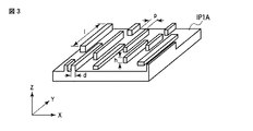
図3は、指向性散乱光を射出可能とする界面部の構成の一例を概略的に示す斜視図である。図3には、界面部IP1Aが、各々が直線状であり且つ面内で方向が揃った複数の凹部又は凸部を含んでいる場合を描いている。図3に示す例では、高散乱方向はX軸に平行であり、低散乱方向はY軸に平行である。 FIG. 3 is a perspective view schematically showing an example of the configuration of the interface portion that can emit directional scattered light. FIG. 3 illustrates a case where the interface portion IP1A includes a plurality of concave portions or convex portions that are each linear and have the same direction in the plane. In the example shown in FIG. 3, the high scattering direction is parallel to the X axis and the low scattering direction is parallel to the Y axis.
界面部IP1Aが各々が直線状であり且つ面内で方向が揃った複数の凹部又は凸部を含んでいる場合、これらの長さl、幅d、高さ又は深さh、及び間隔pの少なくとも1つは、ランダムであることが好ましい。
凹部又は凸部の長さlの平均値は、例えば10μm以上とする。幅dの平均値は、例えば0.1〜10μmの範囲内とする。深さ又は高さhの平均値は、例えば0.1〜10μmの範囲内とし、典型的には0.1〜0.4μmの範囲内とする。凹部又は凸部間の間隔pの平均値は、例えば、0.1〜10μmの範囲内とする。
When the interface portion IP1A is a straight line and includes a plurality of concave portions or convex portions whose directions are aligned in the plane, these length l, width d, height or depth h, and interval p At least one is preferably random.
The average value of the lengths 1 of the recesses or projections is, for example, 10 μm or more. The average value of the width d is, for example, in the range of 0.1 to 10 μm. The average value of the depth or height h is, for example, in the range of 0.1 to 10 μm, and typically in the range of 0.1 to 0.4 μm. The average value of the space | interval p between a recessed part or a convex part shall be in the range of 0.1-10 micrometers, for example.
界面部IP1Bは、界面部IP1Aと隣り合っている。図1及び図2に示す例では、界面部IP1Bは、界面部IP1Aに隣接している。 The interface portion IP1B is adjacent to the interface portion IP1A. In the example shown in FIGS. 1 and 2, the interface portion IP1B is adjacent to the interface portion IP1A.
界面部IP1Bは、白色光で照明した際に指向性散乱光を射出するように構成された複数の凹部又は凸部を備えている。界面部IP1Bは、高散乱方向が互いに異なっていることを除いては、界面部IP1Aと同様の構成を有している。図1及び図2に示す例では、これら界面部は、高散乱方向が互いに直交している。界面部IP1Bは、省略してもよい。 The interface portion IP1B includes a plurality of concave portions or convex portions configured to emit directional scattered light when illuminated with white light. The interface portion IP1B has the same configuration as the interface portion IP1A except that the high scattering directions are different from each other. In the example shown in FIGS. 1 and 2, the high scattering directions of these interface portions are orthogonal to each other. The interface part IP1B may be omitted.
表示体100が界面部IP1Bを含んでいる場合、表示部DP1Aと表示部DP1Bとは、典型的には、特定の観察方向から観察した場合に、互いに異なった明るさを呈する。それゆえ、例えば、これら表示部の対比により、表示体100に所望の像を表示させることができる。
When the
界面部IP2は、界面部IP1A及びIP1Bと隣り合っている。図1及び図2に示す例では、界面部IP2は、後述する界面部IP3を間に挟んで、界面部IP1Aと隣り合っている。 The interface part IP2 is adjacent to the interface parts IP1A and IP1B. In the example shown in FIGS. 1 and 2, the interface portion IP2 is adjacent to the interface portion IP1A with an interface portion IP3 described later interposed therebetween.
界面部IP2は、複屈折性を示すように構成された複数の凹部又は凸部を備えている。界面部IP2を構成している複数の凹部又は凸部は、界面部IP2の遅相軸が、界面部IP1Aの高散乱方向に平行であるか、又は、上記高散乱方向と所定の角度で交わるように設けられている。こうすると、後で説明するように、表示体100の真偽判定が容易となる。
The interface portion IP2 includes a plurality of concave portions or convex portions configured to exhibit birefringence. The plurality of concave portions or convex portions constituting the interface portion IP2 has the slow axis of the interface portion IP2 parallel to the high scattering direction of the interface portion IP1A or intersects the high scattering direction at a predetermined angle. It is provided as follows. This facilitates authenticity determination of the
界面部IP2の遅相軸は、界面部IP1Aの高散乱方向に平行であるか、又は、上記高散乱方向と直交していることが好ましい。こうすると、後で説明するように、表示体100の真偽判定が更に容易となる。また、こうすると、界面部IP1A及びIP2の各々を構成している複数の凹部又は凸部の設計及び形成が容易となる。
It is preferable that the slow axis of the interface portion IP2 is parallel to the high scattering direction of the interface portion IP1A or orthogonal to the high scattering direction. This further facilitates the authenticity determination of the
界面部IP2は、例えば、回折格子パターンを形成している。ここで「回折格子」とは、照明光を照射することにより回折波を生じる構造を意味している。「回折格子」には、以下で例示する複数の溝のみならず、ホログラムに記録された干渉縞なども含まれる。 The interface part IP2 forms, for example, a diffraction grating pattern. Here, the “diffraction grating” means a structure that generates a diffracted wave when irradiated with illumination light. The “diffraction grating” includes not only a plurality of grooves exemplified below but also interference fringes recorded on a hologram.
界面部IP2は、例えば、一次元的に配列した複数の溝を含んでいる。これら溝の各々は、直線状であってもよく、曲線状であってもよい。図1及び図2に示す例では、界面部IP2は、Y軸に沿って互いに平行に配列された複数の溝を含んでいる。 The interface part IP2 includes, for example, a plurality of grooves arranged one-dimensionally. Each of these grooves may be linear or curved. In the example shown in FIGS. 1 and 2, the interface portion IP2 includes a plurality of grooves arranged in parallel to each other along the Y axis.
界面部IP2に設けられた複数の凹部又は凸部は、例えば偏光分離効果に基づいて、複屈折性を示す。以下、図1及び図2に示す構造を例として、この偏光分離効果について説明する。 The plurality of concave portions or convex portions provided in the interface portion IP2 exhibit birefringence based on, for example, the polarization separation effect. Hereinafter, the polarization separation effect will be described using the structure shown in FIGS. 1 and 2 as an example.
図1及び図2に示す例では、界面部IP2は、互いに平行な複数の溝を含んでいる。以下、この溝に対して垂直に振動する偏光をTE偏光と呼び、この溝に対して平行に振動する偏光をTM偏光と呼ぶ。 In the example shown in FIGS. 1 and 2, the interface part IP2 includes a plurality of grooves parallel to each other. Hereinafter, polarized light that vibrates perpendicularly to the groove is referred to as TE polarized light, and polarized light that vibrates parallel to the groove is referred to as TM polarized light.
これら複数の溝の周期をdとし、入射光の波長をλとし、その入射角をθ0とする。このとき、下記式(1)の条件が満たされていれば、界面部IP2は、有効屈折率がneffである薄膜と同視できる。この有効屈折率neffは、入射光の偏光方向によって異なり、第1次近似では、それぞれ、下記式(2)及び(3)により表される。 The period of the plurality of grooves is d, the wavelength of incident light is λ, and the incident angle is θ 0 . At this time, if the condition of the following formula (1) is satisfied, the interface portion IP2 can be regarded as a thin film having an effective refractive index of n eff . This effective refractive index n eff varies depending on the polarization direction of incident light, and is expressed by the following equations (2) and (3) in the first-order approximation, respectively.
dcosθ0<λ …(1)
TE偏光:nTE={(1−f)n1 2+fn2 2}1/2 …(2)
TM偏光:nTM=[n1 2n2 2/{fn1 2+(1−f)n2 2}]1/2 …(3)
式中、
n1は、複数の溝が設けられた層と接している外界の屈折率を表す。
n2は、複数の溝が設けられた層の屈折率を表す。
fは、周期dに対する各溝の幅の比を表す。
dcos θ 0 <λ (1)
TE polarized light: n TE = {(1-f) n 1 2 + fn 2 2 } 1/2 (2)
TM polarization: n TM = [n 1 2 n 2 2 / {fn 1 2 + (1-f) n 2 2 }] 1/2 (3)
Where
n 1 represents the refractive index of the outside world in contact with the layer provided with the plurality of grooves.
n 2 represents the refractive index of the layer in which a plurality of grooves are provided.
f represents the ratio of the width of each groove to the period d.
式(2)及び(3)から分かるように、fが0又は1でない場合には、TE偏光の有効屈折率nTEとTM偏光の有効屈折率nTMとは、互いに異なっている。これを「構造性複屈折」と呼ぶ。この構造性複屈折により、上記の複数の溝に入射した光は、下記
式(4)により表される位相差δを生じる。
As can be seen from the equations (2) and (3), when f is not 0 or 1, the effective refractive index n TE of TE- polarized light and the effective refractive index n TM of TM-polarized light are different from each other. This is called “structural birefringence”. Due to this structural birefringence, light incident on the plurality of grooves generates a phase difference δ represented by the following formula (4).
δ=(nTE−nTM)h …(4)
式中、hは、複数の溝の深さを表す。式(4)から明らかなように、深さhを調整することにより、所望の位相差δを生じさせることが可能となる。
δ = (n TE −n TM ) h (4)
In the formula, h represents the depth of the plurality of grooves. As is apparent from the equation (4), it is possible to generate a desired phase difference δ by adjusting the depth h.
界面部IP2が一次元的に配列した複数の凹部又は凸部を備えている場合、その平均周期dは、200nm乃至500nmの範囲内とすることが好ましく、250nm乃至400nmの範囲内とすることがより好ましい。このような構成を採用すると、入射光として可視光を用いた場合にも、幅広い角度範囲で、上記式(1)の条件を満足させることができる。 When the interface portion IP2 includes a plurality of concave portions or convex portions arranged one-dimensionally, the average period d is preferably in the range of 200 nm to 500 nm, and preferably in the range of 250 nm to 400 nm. More preferred. When such a configuration is employed, even when visible light is used as incident light, the condition of the above formula (1) can be satisfied in a wide angle range.
界面部IP2が一次元的に配列した複数の凹部又は凸部を備えている場合、その平均高さ又は深さhは、50nm乃至200nmの範囲内とすることが好ましく、70nm乃至140nmの範囲内とすることがより好ましい。このような構成を採用すると、後述する直線偏光子を介して観察した場合において、直線偏光子の吸収軸の向きに応じた明るさの変化がより大きくなる。 When the interface portion IP2 includes a plurality of concave portions or convex portions arranged one-dimensionally, the average height or depth h is preferably in the range of 50 nm to 200 nm, preferably in the range of 70 nm to 140 nm. More preferably. When such a configuration is adopted, the brightness change according to the direction of the absorption axis of the linear polarizer becomes larger when observed through a linear polarizer described later.
界面部IP3は、上述した各界面部と隣り合っている。界面部IP3は、平坦面からなる。界面部IP3は、省略してもよい。 The interface portion IP3 is adjacent to each interface portion described above. Interface part IP3 consists of a flat surface. The interface part IP3 may be omitted.
図1及び図2に示す例では、界面部IP3は、界面部IP2に隣接している。このような構成を採用すると、界面部IP2の存在が悟られ難くなる。それゆえ、表示体100の偽造がより困難となる。
In the example shown in FIGS. 1 and 2, the interface portion IP3 is adjacent to the interface portion IP2. When such a configuration is adopted, it is difficult to recognize the presence of the interface portion IP2. Therefore, forgery of the
表示体100は、上述した通り、白色光で照明した際に指向性散乱光を射出するように構成された複数の凹部又は凸部が設けられた界面部IP1Aと、複屈折性を示すように構成された複数の凹部又は凸部が設けられた界面部IP2とを備えている。
As described above, the
界面部IP1Aに対応した表示部DP1Aは、先の説明から明らかな通り、観察方向に応じて明るさが変化する。この変化は、観察者が目視により視認することができる。他方、界面部IP2に対応した表示部DP2は、複屈折性を示す。それゆえ、この表示部DP2を直線偏光子を介して観察すると、その観察方向に応じて明るさが変化する。したがって、表示体100では、目視観察による確認と、直線偏光子を介した観察による確認とを組み合わせて、二重の真偽判定を行うことができる。それゆえ、この表示体100は、偽造防止効果が高い。
As is clear from the above description, the brightness of the display portion DP1A corresponding to the interface portion IP1A changes according to the observation direction. This change can be visually recognized by an observer. On the other hand, the display part DP2 corresponding to the interface part IP2 exhibits birefringence. Therefore, when the display unit DP2 is observed through a linear polarizer, the brightness changes according to the observation direction. Therefore, in the
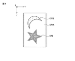
図4は、図1及び図2に示す表示体100を他の方向から観察した場合の例を示す平面図である。図4に示す通り、表示体100の観察方向を変えることにより、表示部DP1Aと表示部DP1Bとの明るさの差を変化させることができる。
FIG. 4 is a plan view showing an example when the
このような明るさの変化は、目視によって確認できる。それゆえ、表示体100は、それを目視で観察するだけでも、比較的高い偽造防止効果を達成できる。このことは、界面部IP2により付与された複屈折性という機能をカモフラージュすることを可能とする。即ち、この表示体100を偽造しようとする者は、上述した目視観察による明るさの変化に注目させられるため、表示体100の界面部IP2に複屈折性という更なる機能が付与されていることに気付き難い。それゆえ、表示体100は、偽造することが困難である。
Such a change in brightness can be confirmed visually. Therefore, the
以上において説明した表示体100は、界面部IP1A及びIP2の双方が、複数の凹部又は凸部を備えている。それゆえ、これらに対応した構造を有した原版を準備し、これを用いて複製を行うことにより、両者の構成、位置関係及び機能を維持したまま、精密な製造を行うことができる。それゆえ、真正品である表示体100に対する信頼度が高くなり、真偽判定の確実さが増す。
In the
表示体100の真偽判定は、上述した通り、直線偏光子を介した観察により行う。より具体的には、表示体100の真偽判定方法は、直線偏光子を介して、少なくとも表示部DP2を観察することを含んでいる。
The authenticity determination of the
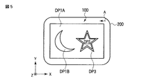
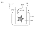
図5は、図1及び図2に示す表示体を直線偏光子を介して観察した場合の例を示す平面図である。図6は、図1及び図2に示す表示体を直線偏光子を介して観察した場合の他の例を示す平面図である。なお、これら図5及び図6では、表示部DP2以外の明暗の変化は図示していない。 FIG. 5 is a plan view showing an example when the display shown in FIGS. 1 and 2 is observed through a linear polarizer. FIG. 6 is a plan view showing another example when the display body shown in FIGS. 1 and 2 is observed through a linear polarizer. In FIGS. 5 and 6, changes in brightness other than the display portion DP2 are not shown.
図5に示す直線偏光子200は、X軸に平行な吸収軸Aを有している。図6に示す直線偏光子200は、Y軸に平行な吸収軸Aを有している。
A
表示体100と直線偏光子200との配置を図5に示す関係とした場合、表示部DP2は、直線偏光子200を介して観察すると、比較的明るく見える。表示体100と直線偏光子200との配置を図6に示す関係とした場合、表示部DP2は、直線偏光子200を介して観察すると、比較的暗く見える。このように、表示体100の表示部DP2は、直線偏光子200を介して観察すると、直線偏光子の吸収軸の向きに応じた明るさの変化を生じる。よって、この明るさの変化の有無を調べることにより、表示体100の真偽を判定できる。
When the arrangement of the
上述した通り、界面部IP2を構成している複数の凹部又は凸部は、界面部IP2の遅相軸が、界面部IP1Aの高散乱方向に平行であるか、又は、上記高散乱方向と所定の角度で交わるように設けられている。よって、表示体100の真偽を判定する観察者は、表示部DP1Aの高散乱方向を基準として、界面部IP2の遅相軸の向きを知ることができる。即ち、表示体100の真偽を判定する観察者は、表示部DP1Aの高散乱方向を基準として、直線偏光子200の吸収軸Aの向きを、界面部IP2の遅相軸の向きに合わせて容易に設定することができる。この点については、後で図7乃至図10を参照しながら、更に詳しく説明する。
As described above, the plurality of concave portions or convex portions constituting the interface portion IP2 has the slow axis of the interface portion IP2 parallel to the high scattering direction of the interface portion IP1A or is predetermined with the high scattering direction. It is provided to intersect at an angle of. Therefore, the observer who determines the authenticity of the
直線偏光子200としては、例えば、直線偏光フイルムを用いる。直線偏光子200は、拡散板を更に備えていることが好ましい。この場合、拡散板は、例えば、直線偏光子200の前面、背面、又は両面に貼り合わせて用いる。拡散板を用いると、直線偏光子200を介して表示部DP2を観察した場合に、観察方向の変化に応じた明るさの変化を、より明瞭に視認することが可能となる。
As the
以上において説明した表示体100には、種々の変形が可能である。
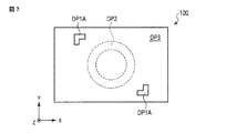
図7は、本発明の他の態様に係る表示体を概略的に示す平面図である。図7に示す表示体100は、表示部DP1Aと、表示部DP2と、これらの間に介在した表示部DP3とを含んでいる。
Various modifications can be made to the
FIG. 7 is a plan view schematically showing a display body according to another aspect of the present invention. The
図7に示す表示体100では、界面部IP1Aに設けられた複数の凹部又は凸部の高散乱方向を、Y軸と平行としている。よって、表示体100をY軸に平行な方向から観察すると、表示部DP1Aは明るく見える。
In the
また、図7に示す表示体100では、界面部IP2に設けられた複数の凹部又は凸部の遅相軸も、Y軸と平行としている。即ち、図7に示す表示体100は、上記遅相軸の方向が上記高散乱方向と平行となるように構成されている。
Moreover, in the
図7に示す表示体100の真偽判定は、例えば、以下のようにして行うことができる。
The authenticity determination of the
まず、直線偏光子を、直線偏光子の吸収軸と上記高散乱方向とが互いに平行となるように配置する。この際、表示体100の真偽判定を行う観察者は、表示部DP1Aが最も明るく見える観察角度を調べることにより、上述した高散乱方向を知ることができる。即ち、表示部DP1Aは、直線偏光子の吸収軸の向きを定めるためのガイドとなる。
First, the linear polarizer is arranged so that the absorption axis of the linear polarizer and the high scattering direction are parallel to each other. At this time, an observer who determines the authenticity of the
図8は、図7に示す表示体を直線偏光子を介して観察した場合の一例を示す平面図である。図8では、直線偏光子200の吸収軸Aは、Y軸と平行である。即ち、直線偏光子200の吸収軸Aは、上述した遅相軸に直交している。この場合、表示体100の表示部DP2は、比較的暗く見える。
FIG. 8 is a plan view showing an example when the display shown in FIG. 7 is observed through a linear polarizer. In FIG. 8, the absorption axis A of the
次に、直線偏光子の吸収軸の向きを変化させる。
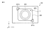
図9は、図7に示す表示体を直線偏光子を介して観察した場合の他の例を示す平面図である。図9では、直線偏光子200の吸収軸Aは、Y軸と45゜の角度を為している。即ち、直線偏光子200の吸収軸Aは、上述した遅相軸と45゜の角度を為している。この場合、表示体100の表示部DP2は、図8に示す場合と比較して、より明るく見える。なお、上述した位相差δの設定によっては、図9に示す場合に、図8に示す場合と比較して、表示部DP2により暗い像を表示させることもできる。この位相差δの設定は、例えば、上述した平均深さ又は高さhを調整することにより行うことができる。
Next, the direction of the absorption axis of the linear polarizer is changed.
FIG. 9 is a plan view showing another example when the display shown in FIG. 7 is observed through a linear polarizer. In FIG. 9, the absorption axis A of the
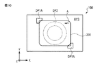
図10は、図7に示す表示体を直線偏光子を介して観察した場合の他の例を示す平面図である。図10では、直線偏光子200の吸収軸Aは、Y軸と直交している。即ち、直線偏光子200の吸収軸Aは、上述した遅相軸と直交している。この場合、表示体100の表示部DP2は、図9に示す場合と比較して、更に明るく見える。
FIG. 10 is a plan view showing another example when the display shown in FIG. 7 is observed through a linear polarizer. In FIG. 10, the absorption axis A of the
このように、直線偏光子200の吸収軸Aの向きを変化させることにより、表示部DP2の明暗を変化させることができる。特に、図10に示す条件では、直線偏光子200を介して観察した場合に、表示部DP2と表示部DP3とは、明るさがほぼ同じとなる。それゆえ、この条件では、表示部DP2と表示部DP3とを互いに判別できない。他方、図8及び図9に示す条件では、表示部DP2と表示部DP3とを、互いに判別することができる。よって、直線偏光子200の吸収軸Aの向きを変化させることにより、表示部DP2と表示部DP3との対比により表示される像を可視化又は不可視化することができる。
Thus, by changing the direction of the absorption axis A of the
なお、上述した通り、直線偏光子200は、拡散板を備えていることが好ましい。こうすると、図10に示す条件において、表示部DP2と表示部DP3とのコントラストが低下する。それゆえ、こうすると、これら表示部の判別を更に困難とすることができる。
As described above, the
図1乃至図10を参照しながら説明した表示体100は、白色光で照明した際に指向性散乱光を射出するように構成された複数の凹部又は凸部が設けられた界面部を、3つ以上備えていてもよい。例えば、これら界面部の高散乱方向が段階的且つ単調に変化するような構成を採用すると、観察方向の変化に応じて、アニメーション的な像変化を生じさせることができる。
The
図1乃至図10を参照しながら説明した表示体100において、各界面部は、セル単位で形成されていてもよい。これらセルを画素として配することで、容易に表示画像を規定することができる。即ち、こうすると、表示体100の設計が容易となる。
In the
なお、各界面部をセル単位で形成する場合、セルの一辺の大きさを100μm程度とすることは十分に可能である。この場合、通常の観察条件における人間の目の分解能以下の細かさで像を表示することができる。すなわち、十分に高精細な像を表示できる。 In addition, when each interface part is formed in a cell unit, it is sufficiently possible to set the size of one side of the cell to about 100 μm. In this case, an image can be displayed with a fineness below the resolution of the human eye under normal observation conditions. That is, a sufficiently high-definition image can be displayed.
図1乃至図10を参照しながら説明した表示体100は、転写箔の一部として使用してもよい。また、表示体100は、印刷物などの表示体付き物品の一部として使用してもよい。
The
以下、本発明の実施例について説明するが、本発明は、これに限定されるものではない。 Examples of the present invention will be described below, but the present invention is not limited thereto.
図1及び図2を参照しながら説明した表示体100を、以下のようにして製造した。
まず、ポリエチレンテレフタレート(PET)フイルム上に、紫外線硬化性樹脂を、グラビアロールコータを用いて塗工した。この樹脂層を、凹凸構造を設けた金属版に押し当てて、メタルハライドランプを用いて紫外線を照射した。硬化した樹脂層から金属版を剥離し、一方の主面に複数の凹部又は凸部が形成されたレリーフ層10を得た。このレリーフ層10のうち複数の凹部又は凸部が形成された主面上に、真空蒸着法によって、アルミニウムを蒸着させた。このようにして、光反射性材料層20を得た。
The
First, an ultraviolet curable resin was coated on a polyethylene terephthalate (PET) film using a gravure roll coater. This resin layer was pressed against a metal plate provided with a concavo-convex structure and irradiated with ultraviolet rays using a metal halide lamp. The metal plate was peeled from the cured resin layer to obtain a
レリーフ層10と光反射性材料層20との界面は、界面部IP1A、IP1B、IP2、及びIP3を含んでいた。界面部IP1Aには、各々が直線状であり且つ一次元的に配列した複数の凹部又は凸部を設けた。この複数の凹部又は凸部の高さは、100nm〜400nmの範囲内でランダムとし、その間隔は0.1μm〜1μmの範囲内でランダムとした。界面部IP1Bには、高散乱方向が直交していることを除いては、界面部IP1Aと同様の複数の凹部又は凸部を設けた。界面部IP2には、300nmの周期で一次元的に配列した複数の溝を形成した。界面部IP3は、平坦面とした。
The interface between the
光反射性材料層20の上に、グラビアロールコータを用いて、接着剤を塗工した。このようにして、粘着層30を得た。得られた表示体100を紙基材に転写し、PETフイルムを除去した。このようにして、表示体100を含んだ印刷物を得た。
An adhesive was applied on the light
第1に、この印刷物を、通常の照明光の下で目視で観察した。その結果、表示体100の表示部DP1Aは比較的明るく見えたのに対し、表示部DP1Bは比較的暗く見えた。印刷物をZ軸の周りに90゜回転させて同様の観察をしたところ、表示部DP1A及び表示部DP1Bの明暗が逆転した。
First, the printed material was visually observed under normal illumination light. As a result, the display portion DP1A of the
第2に、この印刷物を、直線偏光子を介して観察した。まず、直線偏光子の吸収軸が界面部IP1Aの高散乱方向と平行となるように、直線偏光子を配置した。その後、この直線偏光しの吸収軸の向きを、Z軸の周りに回転させた。その結果、表示部DP2の明るさが変化した。 Second, the printed material was observed through a linear polarizer. First, the linear polarizer was arranged so that the absorption axis of the linear polarizer was parallel to the high scattering direction of the interface part IP1A. Thereafter, the direction of the absorption axis of the linearly polarized light was rotated around the Z axis. As a result, the brightness of the display unit DP2 has changed.
以上の通り、表示体100を含んだ上記の印刷物は、目視で観察した場合にも、直線偏光子を介して観察した場合にも、観察方向の変化に応じて、表示画像の明るさが変化した。よって、この観察結果に基づいて、上記印刷物が真正品であることを、確実に判別することができた。
As described above, the printed matter including the
10…レリーフ層、20…光反射性材料層、30…粘着層、100…表示体、200…直線偏光子、A…吸収軸、DP1A…表示部、DP1B…表示部、DP2…表示部、DP3…表示部、IP1A…界面部、IP1B…界面部、IP2…界面部、IP3…界面部。
DESCRIPTION OF
Claims (8)
前記第1界面部が最大の光散乱能を示す第1方向と、前記第2界面部の遅相軸に平行な第2方向とは、互いに平行であるか又は互いに所定の角度で交わっている表示体。 A first interface portion provided with a first plurality of recesses or projections configured to emit directional scattered light when illuminated with white light, adjacent to the first interface portion, and birefringent. A second interface portion provided with a plurality of second concave portions or convex portions configured to show,
The first direction in which the first interface portion exhibits the maximum light scattering ability and the second direction parallel to the slow axis of the second interface portion are parallel to each other or intersect at a predetermined angle. Display body.
Priority Applications (1)
| Application Number | Priority Date | Filing Date | Title |
|---|---|---|---|
| JP2011057005A JP2012192568A (en) | 2011-03-15 | 2011-03-15 | Displaying body and method for determining authenticity |
Applications Claiming Priority (1)
| Application Number | Priority Date | Filing Date | Title |
|---|---|---|---|
| JP2011057005A JP2012192568A (en) | 2011-03-15 | 2011-03-15 | Displaying body and method for determining authenticity |
Publications (1)
| Publication Number | Publication Date |
|---|---|
| JP2012192568A true JP2012192568A (en) | 2012-10-11 |
Family
ID=47084961
Family Applications (1)
| Application Number | Title | Priority Date | Filing Date |
|---|---|---|---|
| JP2011057005A Withdrawn JP2012192568A (en) | 2011-03-15 | 2011-03-15 | Displaying body and method for determining authenticity |
Country Status (1)
| Country | Link |
|---|---|
| JP (1) | JP2012192568A (en) |
-
2011
- 2011-03-15 JP JP2011057005A patent/JP2012192568A/en not_active Withdrawn
Similar Documents
| Publication | Publication Date | Title |
|---|---|---|
| CN101361026B (en) | Optical device, labeled article, optical kit and discrimination method | |
| KR101126938B1 (en) | Indicator and information printed matter | |
| US9348070B2 (en) | Security devices | |
| JP5045328B2 (en) | Optical element, labeled article, optical kit, and discrimination method | |
| CN101952128A (en) | Security element and method for producing the same | |
| JP2014191337A (en) | Image display body and article | |
| JP6225408B2 (en) | Display object and its authenticity determination method | |
| JP4978403B2 (en) | Optical element, labeled article, optical kit, and discrimination method | |
| JP2015068849A (en) | Display and labeled goods | |
| JP5909856B2 (en) | Display and labeled goods | |
| JP5125418B2 (en) | Optical element, labeled article, optical kit, and discrimination method | |
| JP6102051B2 (en) | Authenticity judgment method | |
| JP5245294B2 (en) | Information recording medium and information reading apparatus | |
| JP5909844B2 (en) | Display and printed information | |
| JP2016080848A (en) | Display body and article with display body | |
| JP5349772B2 (en) | Display and labeled goods | |
| JP5659786B2 (en) | Laminated body and method for producing the same | |
| JP5040557B2 (en) | Optical element, labeled article and optical kit | |
| JP5380791B2 (en) | Optical element, labeled article, optical kit, and discrimination method | |
| JP2012192568A (en) | Displaying body and method for determining authenticity | |
| JP5141108B2 (en) | Optical element, labeled article, optical kit, and discrimination method | |
| JP5028643B2 (en) | Laminated body, adhesive label, recording medium, labeled article and discrimination method | |
| JP5028642B2 (en) | Laminated body, adhesive label, recording medium, labeled article and discrimination method | |
| JP2017032900A (en) | Display body and article having display body |
Legal Events
| Date | Code | Title | Description |
|---|---|---|---|
| RD02 | Notification of acceptance of power of attorney |
Free format text: JAPANESE INTERMEDIATE CODE: A7422 Effective date: 20130919 |
|
| RD07 | Notification of extinguishment of power of attorney |
Free format text: JAPANESE INTERMEDIATE CODE: A7427 Effective date: 20131008 |
|
| A300 | Withdrawal of application because of no request for examination |
Free format text: JAPANESE INTERMEDIATE CODE: A300 Effective date: 20140603 |