JP2012192587A - Cassette attachment device and cassette - Google Patents
Cassette attachment device and cassette Download PDFInfo
- Publication number
- JP2012192587A JP2012192587A JP2011057588A JP2011057588A JP2012192587A JP 2012192587 A JP2012192587 A JP 2012192587A JP 2011057588 A JP2011057588 A JP 2011057588A JP 2011057588 A JP2011057588 A JP 2011057588A JP 2012192587 A JP2012192587 A JP 2012192587A
- Authority
- JP
- Japan
- Prior art keywords
- cassette
- rotating body
- lock
- locking
- unlocking
- Prior art date
- Legal status (The legal status is an assumption and is not a legal conclusion. Google has not performed a legal analysis and makes no representation as to the accuracy of the status listed.)
- Granted
Links
Images


Landscapes
- Electronic Switches (AREA)
- Impression-Transfer Materials And Handling Thereof (AREA)
Abstract
【課題】カセットのロックを解除する操作と装置本体からの抜き取り操作とを同時に行うことが可能なカセット取付装置を提供する。
【解決手段】ロック部材106は、装置本体に差し込んだカセットをロックするロック位置と、ロックを解除してカセットを装置本体から抜き取り可能にするロック解除位置の間を移動する。また、押出し部材107は、装置本体に設けた受け部材111と当接してカセットを抜き取り方向に押し出す押出し位置と、退避位置との間を移動する。そして、カセットの表面に回動自在に取り付けられているロック解除部材100の第1位置から第2位置への回動動作に連動して、ロック部材106はロック位置からロック解除位置へと移動し、押出し部材107は退避位置から押出し位置へと移動する。
【選択図】図4To provide a cassette mounting device capable of simultaneously performing an operation of unlocking a cassette and an operation of removing the cassette from the apparatus main body.
A lock member 106 moves between a lock position for locking a cassette inserted into the apparatus main body and a lock release position for releasing the lock so that the cassette can be removed from the apparatus main body. Further, the pushing member 107 moves between a pushing position where the pushing member 107 comes into contact with a receiving member 111 provided in the apparatus main body and pushes the cassette in the extracting direction, and a retracted position. The lock member 106 moves from the lock position to the lock release position in conjunction with the rotation of the lock release member 100 that is rotatably attached to the surface of the cassette from the first position to the second position. The pushing member 107 moves from the retracted position to the pushing position.
[Selection] Figure 4
Description
本発明は、熱転写プリンタなどの装置本体にカセットを着脱自在に取り付けるカセット取付機構(以下、「カセット取付装置」という)に関する。 The present invention relates to a cassette mounting mechanism (hereinafter referred to as “cassette mounting device”) that detachably mounts a cassette to an apparatus main body such as a thermal transfer printer.
熱転写プリンタはインクリボンに塗布された固形インクを印字ヘッドにより用紙に押し付けて転写することにより印刷を行うもので、インクリボンはロールに巻回してリボンカセットに収納しており、インク切れ時にはリボンカセットごと交換するように、インクリボンカセットは熱転写プリンタ本体から着脱自在に取り外し可能な構成となっている。 The thermal transfer printer performs printing by pressing the solid ink applied to the ink ribbon against the paper by the print head and transferring it. The ink ribbon is wound around a roll and stored in the ribbon cassette. The ink ribbon cassette is configured to be detachable from the thermal transfer printer main body so as to be replaced.
しかしながら、熱転写プリンタを特に業務用に用いる例えばカード処理装置など他の機器と組み合わせて使用する場合には、大量のインクリボンを使用するためインクリボンを券回するロールを大径化しなければならずカセットが大型化する。 However, when the thermal transfer printer is used in combination with other equipment such as a card processing device for business use in particular, a large number of ink ribbons must be used, so the roll for winding the ink ribbon must be enlarged. The cassette becomes larger.
そのため、大型化して重量のあるカセットを熱転写プリンタから抜き取って再び装着するには相当な作業を必要とし、カセットの着脱にはより良好な操作性および利便性が望まれる。 Therefore, considerable work is required to remove a large and heavy cassette from the thermal transfer printer and remount it, and better operability and convenience are desired for attaching and detaching the cassette.
特許文献1には、リボンカセットのロックを解除するためのイジェクト部材をプリンタ本体に対してスライド可能に設けて、このイジェクト部材をスライドさせることでロックを解除し、このスライドに連動してイジェクト部材に設けた押出し部材がリボンカセットを引出方向に押し出すと共に、バネ力にてリボンカセットが飛び出すような熱転写プリンタが開示されている。
In
特許文献1の装置ではイジェクト部材はプリンタの本体側に設けられており、リボンカセットの抜き取り動作としては、操作者は先ずイジェクト部材をスライドさせてロックを解除し、次に押し出されたリボンカセットを掴んで引き出すという2通りの操作が必要となる。しかも、操作者がイジェクト部材を操作している状態では、リボンカセットはフリーの状態で本体から飛び出してくることになり、場合によってはリボンカセットが飛び出す勢いで落下することも起こりかねない。そのために、操作者は両手でイジェクト部材とリボンカセットに触れていなければならず操作性の面で問題がある。
In the apparatus of
以上の点より本発明は、カセットのロックを解除する操作と装置本体からの抜き取り動作とを同時に行うことが可能なカセット取付装置を提供することを目的としている。 In view of the above, an object of the present invention is to provide a cassette mounting apparatus capable of simultaneously performing an operation of releasing the lock of the cassette and an operation of extracting the cassette from the apparatus main body.
上記課題を達成するため本発明のカセット取付装置は、装置本体にカセットを着脱自在に取り付けるカセット取付装置において、前記装置本体に差し込んだ前記カセットをロックするロック位置と前記ロックを解除して前記カセットを前記装置本体から抜き取り可能なロック解除位置との間で移動可能なロック部材と、前記ロック部材が前記ロック解除位置にあるときに前記装置本体に設けた受け部材と当接して前記カセットを抜き取り方向に押し出す押出し位置と前記受け部材から離間した退避位置との間で移動可能な押出し部材と、前記ロック部材及び前記押出し部材と直接又は間接的に連結され、第1位置から第2位置に移動可能なロック解除部材とを備え、前記ロック部材、押出し部材及びロック解除部材は前記カセットに設けられ、前記ロック解除部材が前記第1位置から前記第2位置に移動することで前記ロック部材を前記ロック位置から前記解除位置に移動させ、前記押出し部材を前記退避位置から前記押出し位置に移動させることを特徴としている。 In order to achieve the above object, a cassette mounting apparatus according to the present invention is a cassette mounting apparatus in which a cassette is detachably attached to an apparatus main body, wherein the cassette inserted into the apparatus main body is locked and the lock is released to release the lock. A lock member that can be moved between a lock release position that can be removed from the apparatus main body, and a receiving member that is provided on the apparatus main body when the lock member is in the lock release position, thereby extracting the cassette. A pushing member that is movable between a pushing position that pushes in a direction and a retracted position that is spaced apart from the receiving member, and is directly or indirectly connected to the locking member and the pushing member, and moves from the first position to the second position. The lock member, the push member, and the lock release member are provided in the cassette. Moving the lock member from the lock position to the release position by moving the lock release member from the first position to the second position, and moving the push member from the retracted position to the push position; It is a feature.
そして、前記ロック解除部材は、前記第1位置から前記第2位置に移動した後、前記ロック部材及び前記押出し部材に作用しない第3位置に移動可能に構成したことを特徴としている。 The lock release member is configured to be movable to a third position that does not act on the lock member and the push-out member after moving from the first position to the second position.
また、前記ロック解除部材が前記第1位置から前記第2位置に移動することで、前記押出し部材が第1の方向に移動し、前記ロック解除部材が前記第3位置から前記第1位置に移動することで、前記押出し部材が第2の方向に移動するように構成され、前記押出し部材が前記第1の方向に移動するときは、前記押出し部材と前記ロック部材とが同時に移動し、前記押出し部材が前記第2の方向に移動するときは、前記押出し部材のみが移動することを特徴としている。 Further, when the unlocking member moves from the first position to the second position, the pushing member moves in the first direction, and the unlocking member moves from the third position to the first position. The extruding member is configured to move in the second direction, and when the extruding member moves in the first direction, the extruding member and the locking member move simultaneously, and the extruding member When the member moves in the second direction, only the pushing member moves.
また、前記ロック解除部材に形成される突起部と、前記ロック解除部材の回動に伴い前記突起部と係合する係合片と前記押出し部材とを有する第1回転体と、前記ロック部材を有する第2回転体と、前記ロック位置にある前記ロック部材と係合するよう前記装置本体に設けた係止部材とを備え、前記ロック解除部材の前記第1位置から前記第2位置への回動により前記突起部と前記係合片とが係合して前記第1回転体が前記第1の方向に回動したとき、前記第2回転体は前記第1回転体に連動して回転することで前記ロック部材は前記ロック解除位置に移動して前記係止部材との係合を解除し、前記第1回転体の回転により前記押出し部材が前記押出し位置に移動して前記受け部材と当接することを特徴としている。 A first rotating body having a protrusion formed on the unlocking member, an engagement piece that engages with the protrusion as the unlocking member rotates, and the push member; And a locking member provided on the apparatus main body so as to engage with the lock member at the lock position, and the rotation of the lock release member from the first position to the second position. When the protrusion and the engaging piece engage with each other and the first rotating body rotates in the first direction, the second rotating body rotates in conjunction with the first rotating body. Thus, the locking member moves to the unlocking position to release the engagement with the locking member, and the pushing member moves to the pushing position by the rotation of the first rotating body, so that the receiving member and the receiving member are brought into contact with each other. It is characterized by touching.
また、前記第1回転体と前記第2回転体とを同一軸上に重ねて配置して、互いが接触する面にはそれぞれ傾斜方向が逆向きとなるテーパを形成し、前記第1回転体または前記第2回転体の一方が回転したとき前記第1回転体の前記テーパの立上り部と前記第2回転体の前記テーパの立上り部とが係合していると他方も連動して回転するようにして、前記ロック部材を前記ロック位置の方向に付勢する第1付勢部材を備えて、前記ロック解除部材が前記第1位置から前記第2位置へ回動したとき、前記突起部の前記係合片への押し圧による前記第1回転体の前記第1の方向への回転にて、前記第1回転体の前記テーパの前記立上り部が前記第2回転体の前記テーパの前記立上り部を押し圧して前記第2回転体が回転し、前記ロック部材が前記第1付勢部材の付勢に抗して前記ロック位置に移動し、前記ロック解除部材が前記第2位置へ達して前記突起部が前記係合片を押し圧しなくなると、前記第1付勢部材の付勢による前記第2回転体の第2の方向への回転にて、前記第2回転体の前記テーパの前記立上り部が前記第1回転体の前記テーパの前記立上り部を押し圧して前記第1回転体が回転すると、前記突起部と前記係合片との位置関係が入れ替わり、次に前記ロック解除部材を前記第1位置へと回動させたとき、前記突起部は前記第1回転体が前記第2の方向に回転するよう前記係合片を押し圧することを特徴としている。 In addition, the first rotating body and the second rotating body are arranged on the same axis, and a taper in which the inclination direction is opposite to each other is formed on the surfaces in contact with each other, and the first rotating body Alternatively, when one of the second rotating bodies rotates, when the rising portion of the taper of the first rotating body and the rising portion of the taper of the second rotating body are engaged, the other rotates in conjunction with each other. Thus, the first biasing member that biases the lock member in the direction of the lock position is provided, and when the lock release member rotates from the first position to the second position, The rising portion of the taper of the second rotating body causes the rising portion of the taper of the second rotating body by rotation of the first rotating body in the first direction by the pressing force to the engagement piece. The second rotating body is rotated by pressing the part, and the locking member is When the urging member moves to the lock position against the urging force, the unlocking member reaches the second position, and the protrusion no longer presses the engagement piece, the first urging member By the rotation of the second rotating body in the second direction by the biasing, the rising portion of the taper of the second rotating body presses the rising portion of the taper of the first rotating body to press the first rotating body. When the one rotating body rotates, the positional relationship between the protruding portion and the engaging piece is switched, and then when the unlocking member is rotated to the first position, the protruding portion becomes the first rotating body. Is characterized in that the engagement piece is pressed to rotate in the second direction.
また、前記第1回転体を前記第1の方向に回転するよう付勢する第2付勢部材を備えて、前記ロック解除部材が前記第1位置へ回動するとき、前記第1回転体の前記テーパの立上り部と前記第2回転体の前記テーパの立上り部とは係合しておらず、前記第1回転体は前記突起部と前記係合片との係合にて前記第2の方向へ単独で回転し、前記ロック解除部材の回動にて前記突起部と前記係合片との係合が外れると、前記第2付勢部材に付勢されて前記第1回転体は前記第1の方向へ復帰回転することで前記突起部と前記係合片との位置関係が入れ替わり、次に前記ロック解除部材を前記第1位置から前記第2位置へと回動させたときに前記突起部は前記第1回転体が前記第1の方向に回転するよう前記係合片を押し圧することを特徴としている。 A second urging member that urges the first rotator to rotate in the first direction, and when the unlocking member rotates to the first position, The rising portion of the taper and the rising portion of the taper of the second rotating body are not engaged, and the first rotating body is engaged with the protrusion and the engaging piece to When the protrusion and the engaging piece are disengaged by the rotation of the unlocking member, the first rotating body is urged by the second urging member. The positional relationship between the protrusion and the engagement piece is switched by rotating back in the first direction, and then when the lock release member is rotated from the first position to the second position, The protruding portion is characterized in that the engaging piece is pressed against the first rotating body so as to rotate in the first direction. .
また、前記ロック部材は前記カセットを前記装置本体に差し込む際に前記係止部材と当接する傾斜部を備えて、前記傾斜部での前記係止部材との当接により前記ロック部材が前記ロック解除位置へ移動し、次に前記ロック部材と前記係止部材との当接が外れて前記ロック部材が前記第1付勢部材の付勢により前記ロック位置に移動して前記係止部材と係合するとき、前記ロック部材の前記ロック解除位置への移動で前記第2回転体が前記第1の方向へ回転すると、前記第1回転体は前記第2付勢部材の付勢により前記第2回転体と共に回転することで、前記第1回転体の前記テーパの立上り部と前記第2回転体の前記テーパの立上り部との係合は維持され、前記ロック部材と前記係止部材との当接が外れて前記ロック部材の前記ロック位置への移動で前記第2回転体の前記第2の方向へ回転すると、前記第2回転体の前記テーパの前記立上り部が前記第1回転体の前記テーパの前記立上り部を押し圧することで前記第1回転体も連動して回転することを特徴としている。 The lock member includes an inclined portion that comes into contact with the locking member when the cassette is inserted into the apparatus main body, and the lock member is unlocked by the contact with the locking member at the inclined portion. The lock member and the locking member are disengaged, and the lock member is moved to the lock position by the biasing force of the first biasing member to engage with the locking member. When the second rotating body rotates in the first direction due to the movement of the lock member to the unlocking position, the first rotating body rotates the second rotation by the biasing of the second biasing member. By rotating together with the body, the engagement between the rising part of the taper of the first rotating body and the rising part of the taper of the second rotating body is maintained, and the contact between the lock member and the locking member To the locked position of the locking member When the second rotating body rotates in the second direction by movement, the rising portion of the taper of the second rotating body presses the rising portion of the taper of the first rotating body, thereby pressing the first rotating body. The rotating body also rotates in conjunction with it.
そして、前記ロック解除部材は前記カセットの取っ手部材で構成され、前記取っ手部材は前記カセットの筐体に回動可能に設けられていることを特徴としている。 And the said lock release member is comprised by the handle member of the said cassette, and the said handle member is provided in the housing | casing of the said cassette so that rotation is possible.
前記取っ手部材と前記筐体とを回動自在に連結する連結部において、前記取っ手部材と前記筐体とが接触する面には互いに傾斜方向が逆向きとなるテーパをそれぞれ形成して、前記取っ手部材が前記第3位置にあるとき前記取っ手部材と前記筐体とは前記テーパ同士が係合することを特徴としている。 In the connecting portion for rotatably connecting the handle member and the housing, the surfaces where the handle member and the housing are in contact with each other are formed with tapers whose inclination directions are opposite to each other. When the member is in the third position, the handle member and the housing are characterized in that the tapers are engaged with each other.
そして、前記取っ手部材は第1位置に向けてバネ付勢されていることを特徴としている。 The handle member is spring-biased toward the first position.
また、上記課題を達成するため本発明のカセットは、装置本体に着脱自在に取り付けられるカセットにおいて、前記装置本体に差し込んだ前記カセットをロックするロック位置と前記ロックを解除して前記カセットを前記装置本体から抜き取り可能なロック解除位置との間で移動可能なロック部材と、前記ロック部材が前記ロック解除位置にあるときに前記装置本体から前記カセットを抜き取り方向に押し出す押出し位置と前記カセットが装着可能な装着位置との間で移動可能な押出し部材と、前記ロック部材及び前記押出し部材と直接又は間接的に連結され、第1位置から第2位置に移動可能なロック解除部材と、を備え、前記ロック解除部材が前記第1位置から前記第2位置に移動することで前記ロック部材を前記ロック位置から前記解除位置に移動させ、前記押出し部材を前記装着位置から前記押出し位置に移動させることを特徴としている。 In order to achieve the above object, the cassette according to the present invention is a cassette that is detachably attached to the apparatus main body, wherein the cassette inserted into the apparatus main body is locked and the lock is released to release the lock. A lock member that can be moved between a lock release position that can be extracted from the main body, an extrusion position that pushes the cassette in the extraction direction from the apparatus main body when the lock member is in the lock release position, and the cassette can be mounted. An extruding member movable between a first mounting position and a lock releasing member that is directly or indirectly connected to the locking member and the extruding member and is movable from a first position to a second position, The unlocking member moves from the first position to the second position so that the locking member is released from the locking position. Is moved to the position, it is characterized by moving the pushing member to the pushing position from the mounting position.
本発明に依れば、カセットに取り付けられているロック解除部材を第1位置から第2位置へ回動させるだけでロックの解除とカセットの抜き取り方向への付勢の両方が達成されるために、抜き取りのための操作が容易となるばかりか、操作者がロック解除部材を把持していることでカセットが抜き取り方向への付勢により勢いよく飛び出して落下することも防止できる。そして、ロック解除と引き出しとを同じ操作としたことで、片手でも確実な操作を行うことができ操作性が向上する。 According to the present invention, both the unlocking and the urging in the removing direction of the cassette can be achieved by simply rotating the unlocking member attached to the cassette from the first position to the second position. In addition to facilitating the operation for extraction, it is possible to prevent the cassette from being ejected vigorously due to urging in the extraction direction by the operator holding the lock release member. Since the unlocking operation and the drawer operation are the same, a reliable operation can be performed with one hand, improving operability.
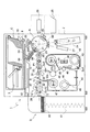
以下、好適な実施の形態としてカード処理装置の例で本発明を説明する。図1に全体構成を示すカード処理装置1が処理するカードは各種証明用のIDカード、商取引用のクレジットカードなどであって、カードに情報を電子的に記録する共に、カードの表面には熱転写プリンタにて画像情報を記録するようになっている。よって、ハウジング2には、情報記録部Aと熱転写プリンタBとカード収容部Cとが備えられる。
Hereinafter, the present invention will be described with reference to an example of a card processing apparatus as a preferred embodiment. The card processed by the
情報記録部Aは、磁気記録部24と、非接触式IC記録部23と、接触式IC記録部27とで構成される。この情報記録部Aは装置仕様に応じて種々の記録部、例えばバーコード記録部などで構成する。
The information recording unit A includes a
上記カード収容部Cは、複数枚のカードを収納するカードカセット3で構成する。このカードカセット3を装置ハウジング2のカセット装着エリアから取り外し可能となっている。
The card accommodating part C is constituted by a
[カード供給部]
装置ハウジング2のカセット装着エリアにはカード収容部Cが設けられ、複数枚のカードを収納するカードカセット3で構成されている。図1に示すカードカセット3は複数のカードを立位姿勢で整列して収納し、同図左端から右端にカードを繰り出す。そしてカードカセット3の先端には分離開口7が設けられ、ピックアップローラ19で最前列のカードから装置内に供給する。
[Card supply section]
A card housing portion C is provided in the cassette mounting area of the
[情報記録部の構成]
上述のカードカセット3から送られたカードは搬入ローラ22にて反転ユニットFに送られる。反転ユニットFは装置フレーム60に旋回動可能に軸受け支持された回転フレーム80と、このフレームに支持された一対、或いは複数のローラ対で構成される。
[Configuration of information recording section]
The card sent from the
図示のものは距離を隔てて前後に配置された2つのローラ対20、21を回転フレーム80に回転自在に軸支持されている。そして、回転フレーム80は旋回モータ(パルスモータなど)で所定角度方向に旋回動し、これに取付けられているローラ対は搬送モータで正逆転方向に回転するように構成されている。この駆動機構は、1つのパルスモータで回転フレーム80の旋回動と、ローラ対20、21の回転をクラッチで切り換えるように構成しても、回転フレーム80の旋回動とローラ対20、21の回転を別駆動に構成してもよい。
In the illustrated example, two roller pairs 20 and 21 arranged at a distance from each other at a distance are axially supported on a
従ってカードカセット3に準備されたカードはピックアップローラ19と分離ローラ(アイドルコロ)9で1枚ずつ分離され下流側の反転ユニットFに送られる。そして反転ユニットFはカードをローラ対20、21でユニット内に搬入し、ローラ対でニップした状態で所定角度方向に姿勢偏向することとなる。
Accordingly, the cards prepared in the
上記反転ユニットFの旋回方向外周には、磁気記録部24と、非接触式IC記録部23及び接触式IC記録部27と、リジェクトスタッカ25が配置されている。そして、ローラ対20、21は、これらの情報記録部23、24、27の何れかに向けて搬入するカード搬入経路65を形成する。尚、図示28はバーコードリーダであり、例えば後述する熱転写プリンタBで印刷したバーコードを読み取って正誤判別(エラー判別)するためのユニットである。
A
反転ユニットFで所定の角度方向に姿勢偏向されたカードをローラ対20、21にて形成されるカード搬入経路65を通して、磁気記録部24或いは非接触式IC記録部23または接触式IC記録部27に移送すると、カードには磁気的若しくは電気的にデータ入力することが可能となる。またこれらの情報記録部で記録ミスが生じた場合にはリジェクトスタッカ25に搬出する。
The
図1においては、反転ユニットFは非接触式IC記録部23に向けて旋回しており、カードはローラ対20、21により記録部23に向けてカード搬入経路65を形成している。非接触式IC記録部23は、ICリーダライタ基板67と、ICリーダライタアンテナ69と、カード搬送パス68とから構成されており、ICリーダライタアンテナ69は、カード搬入経路65を通して、カード搬送パス68に導入されたカードに埋設されているICチップに、ICリーダライタ基板67から送られてくる情報を電波信号で送信する。これにより、ICチップには記録情報が記録されることになる。
In FIG. 1, the reversing unit F rotates toward the non-contact type IC recording unit 23, and the card forms a card carry-in
カード搬送パス68とカード搬送経路P1との間には、ICリーダライタアンテナ67からの電波信号を遮閉する遮閉板70を配置することで、カード搬送経路P1にて搬送途中にある他のカードへの誤って記録されるのを防止している。遮閉板70は、シールド材(電波吸収体)で構成するもので、このシールド材としては、特定帯域の電波を吸収して遮断する材料を選択する。
Between the
上記反転ユニットFの下流側には熱転写プリンタBが設けられ、この熱転写プリンタBにカードを移送するカード搬送経路P1が設けられ、この経路P1に前述の反転ユニットFが配置されている。また、カード搬送経路P1にはカードを搬送する搬送ローラ29、30が配置され、図示しない搬送モータに連結されている。この搬送ローラ29、30は正逆転切り換え可能に構成され、反転ユニットFから熱転写プリンタBにカードを搬送するのと同様に熱転写プリンタBからカードを反転ユニットFに搬送するようになっている。
A thermal transfer printer B is provided on the downstream side of the reversing unit F, a card transport path P1 for transferring a card to the thermal transfer printer B is provided, and the above-described reversing unit F is disposed in the path P1. In addition,
また、搬送ローラ29、30は搬送されるカードをそれぞれ上下一対のローラにて挟持しながら繰り出すローラ対である。そして、搬送ローラ29と搬送ローラ30の間にはスキュー補正装置90が配置されている。詳細には図示しないが、スキュー補正装置90は、カード搬送経路P1の搬送方向に沿った一側に幅寄せ部材、他側にガイド部材をそれぞれ設け、搬送ローラ29、30にて搬送されるカードを幅寄せ部材にてガイド部材に向けて押し出すことで、スキューを矯正したカードが熱転写プリンタBに向けて搬送されるようにするものである。
Further, the
上記熱転写プリンタBの下流側には収容スタッカ60にカードを移送するカード搬送経路P2が設けられている。カード搬送経路P2にはカードを搬送する搬送ローラ(ベルトでも良い)37、38が配置され、図示しない搬送モータに連結されている。
On the downstream side of the thermal transfer printer B, a card transport path P2 for transporting cards to the
搬送ローラ37と搬送ローラ38の間にはデカール機構36が配置され、搬送ローラ37、38間に保持されたカード中央部を押圧することによって、熱転写により生じたカールを矯正する。このためデカール機構36は図示しない昇降機構(カムなど)で図1に示す上下方向に位置移動可能に構成されている。
A decurling mechanism 36 is disposed between the transporting
搬送ローラ37はニップコロ71と、搬送ローラ38はニップコロ72とで、それぞれデカールされるカードをニップしているが、押圧部74が昇降機構によって押し下げられると、受部73は押圧部74を受け止めながらニップコロ71、72と共に下方に移動する。これにより、搬送ローラ37とニップコロ71、及び搬送ローラ38とニップコロ72によるカードのニップが解除されるために、整ったカール矯正を行うことが出来る。
The
「熱転写プリンタ」
熱転写プリンタBは、記録カードの表裏面に顔写真、文字データなど画像を形成する。図示の装置は昇華型インクリボンで画像形成する場合を示している。
"Thermal transfer printer"
The thermal transfer printer B forms images such as face photographs and character data on the front and back surfaces of the recording card. The illustrated apparatus shows a case where an image is formed with a sublimation ink ribbon.
熱転写プリンタBにはサーマルヘッド40とインクリボン41が配置されている。インクリボン41はリボンカセット42に収納され、このリボンカセット42に操出ロール43と巻取ロール44が収容され、巻取ロール44には図示しないワインドモータMr1が連結されている。
The thermal transfer printer B is provided with a
プラテンローラ45に対向する位置にサーマルヘッド40が配置されている。このサーマルヘッド40は、ヘッドコントロール用IC(図示せず)により熱制御される。そして、このヘッドコントロール用ICは、画像データに従ってサーマルヘッド40を加熱制御することにより、インクリボン41を後述する転写フィルム46に画像形成する。このためサーマルヘッド40の熱制御と同期して巻取ロール44が回転し、インクリボン41を所定速度で巻き取るように構成されている。図示39はサーマルヘッド40を冷やす為の冷却ファンである。
A
上記転写フィルム46は転写フィルムカセット50に収納されて、巻取ロール47と操出ロール48に巻回され、この転写フィルム46は熱転写装置であるプラテンローラ31とヒートローラ33に転写画像を移送するように巻装されている。図示49は転写フィルム46の移送ローラであり、その周面にピンチローラ32aと32bが配置され、この移送ローラ49には図示しない駆動モータに連結されている。そして転写フィルム46は、インクリボン41と同一速度で図1反時計回りの方向に移動する。
The
また、ヒートローラ33には、搬入経路P1に配置されているプラテンローラ31に転写フィルム46を介して圧接離間するように昇降機構(図示せず)が設けられている。図4に示すダイアル95は、この昇降機構に連動しており、このダイアル95を回すことにより、ヒートローラ33を手動にて昇降させることができる。
Further, the
このヒートローラ33は加熱ローラで構成され、内部に配置されている加熱手段で転写フィルム46上の画像を記録カード表面に転写する。図示Se1はインクリボン41の位置検出センサであり、図示Se2は転写フィルム46の有無検出センサである。また、熱転写プリンタBには装置内に発生した熱を外に出す為のファン39が設けられている。
The
「収容部」
収容部Dは図1に示すように熱転写プリンタBから送られたカードを収容スタッカ60に収容するように構成されている。この収容スタッカ60は図示しない昇降機構61とレベルセンサで、最上位のカードを検出し、昇降機構61で図1下側に下降移動するように構成されている。
"Container"
The accommodating portion D is configured to accommodate the card sent from the thermal transfer printer B in the
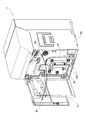
図2は上記したカード処理装置1の外観を示しており、一側が回動自在に軸支されているフロントカバー1Aを開放したときに、リボンカセット42及び転写フィルムカセット50は熱転写プリンタBにそれぞれ形成しているカセット装着エリア内へ差し込んだり抜き取ったりすることが可能なよう着脱自在な構成となっている。また、フロントカバー1Aの裏面にはピン82が設けられており、フロントカバー1Aを本体に閉じることでこのピン82が本体側に設けた差込孔83に挿入したことを検知したときカード処理装置1は動作可能な状態となる。
FIG. 2 shows the external appearance of the
カード処理装置1の熱転写プリンタBから着脱自在にしたリボンカセット42及び転写フィルムカセット50(以下、単に「カセット」と称する)の抜き取り時のロックを解除する操作と取り出し操作、及びカセット装着時の差し込み操作とロックする操作とを容易に行えるようにした本発明によるカセット取付装置の具体的な構成について説明する。
Operation for unlocking and taking out the
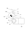
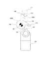
図3は、カード処理装置1から抜き取ったリボンカセット42の外観を示している。転写フィルムカセット50も同様であるが、カセットには操作者が抜き取り時に正対する面には把持するための取っ手部材100が設けられている。取っ手部材100は、カセットの筐体10表面に倒れた状態である第1位置と、第2位置及び筐体10表面から起立した状態である第3位置との間を回動自在に取り付けられている。この取っ手部材100はロック解除部材を兼用しており、取っ手部材100が第1位置と第3位置との間の第2位置にあるときにカセットと熱転写プリンタBとの間のロックが外れてカセットの抜き取りが行えるようになっている。
FIG. 3 shows the appearance of the
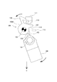
図4は、熱転写プリンタBから着脱自在とするカセット取付装置を平面図にて示すもので、取っ手部材100は上下の辺に穿設した軸孔101にはカセット内に設けられた軸88(図13及び図14)が挿通されており、この軸を支点に第1位置、第2位置及び第3位置の間を回動するように構成されている。
FIG. 4 is a plan view showing a cassette mounting device that is detachable from the thermal transfer printer B. The
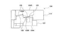
取っ手部材100のカセット側の回動端部には突起部102が形成されている。突起部102と係合する係合片103を備える回転体104は軸105に回動自在に軸支されている。
A
図4と回転体104の側面図を示す図7及び図8にて回転体104の構成を説明すると、回転体104は第1回転体104Aと第2回転体104Bとから成り、第1回転体104Aには係合片103と共に押出し部材107とが設けられ、第2回転体104Bにはロック部材106と突出片114とが設けられている。
The configuration of the
押出し部材107は第1回転体104Aの回転に応じてカセットを抜き取り方向に押し出す押出し位置と退避位置との間を移動する。
The push-out
ロック部材106は第2回転体の回転に応じてロック位置とロック解除位置との間を移動する。また、突出片114は第2回転体104Bの図で時計回りの方向への回転時にカセットに固設されているストッパ115と当接するようになっている。
The
第1回転体104Aと第2回転体104Bはそれぞれの軸孔を挿通する軸107に回転可能なよう重ねて配置されるが、互いが接触する面には回転方向に沿って第1回転体104Aにはテーパ108が複数形成されており、第2回転体104Bにはテーパ109が複数形成されている。テーパ108とテーパ109とは互いに傾斜方向が逆向きとなって噛合い結合している。そして、テーパ108の立上り部108Aとテーパ109の立上り部109Aとが係合している状態(図7)において、第1回転体104Aまたは第2回転体104Bの一方が、立上り部108Aと立上り部109Aとによる係合状態を維持する方向に回転を行うと他方も連動して回転する。
The first
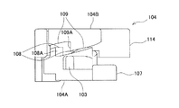
しかるに、第1回転体104Aまたは第2回転体104Bの一方が、立上り部108Aと立上り部109Aとの係合を解除して離反する方向に回転したときは(図8)、他方は連動せずに回転を停止したままである。そして、立上り部108Aと立上り部109Aとが離反した状態で、次に第1回転体104Aまたは第2回転体104Bの一方が、立上り部108Aと立上り部109Aとを近づける方向に回転しても、離反している立上り部108Aと立上り部109Aとが再び当接して係合するまでは一方の回転体には回転力は伝達されない。
However, when one of the first
図4において、係止部材110及び受け部材111は熱転写プリンタBの本体に固定されている。例えばピンにて構成される係止部材110は、図の紙面から鉛直方向に突出しておりロック部材106と係合することでカセットは熱転写プリンタBへロックされる。ロック部材106は、バネ等による第1付勢部材(図示せず)によりロック位置で係止部材110と係合するよう図で時計回りの方向に付勢されている。この第1付勢部材はロック部材106に直接作用するよう設けても良いし、また第2回転体104Bに作用して時計回りの回転力を与えるよう設けても良い。
In FIG. 4, the locking
受け部材111は第1回転体104Aの回転により押出し位置に進出してくる押出し部材107を受け止めて、その反作用力を押出し部材107を介してカセットに与えるものであり、これによりカセットは熱転写プリンタBのカセット装着エリアからの取り外しが容易となる。なお、押出し部材107の退避位置とは、カセットが装着状態で、押出し部材107がカセットを押出す力が働かない位置であり、図4のように受け部材111から離間していても良いし、カセットを押出す力が働かなければ受け部材111に接触していてもよい。
The receiving
上記構成による本発明に係るカセット取付装置の動作について図4から図14までを用いて説明する。 The operation of the cassette mounting apparatus according to the present invention having the above configuration will be described with reference to FIGS.
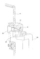
図4は、取っ手部材100が第1位置にあって、ロック部材106はロック位置に位置して係止部材110と係合しており、カセットは熱転写プリンタBにセットされてロックされている状態を示している。
FIG. 4 shows a state in which the
図5は、カセットを熱転写プリンタBから引き出すために、操作者の操作により取っ手部材100を第2位置に回動させた状態を示している。この場合取っ手部材100の突起部102は係合片103を図で左方向から係合して押し圧し、第1回転体104Aを図で反時計回りの方向(第1の方向)に回転させる。第1回転体104Aの図で反時計回りの方向への回転はテーパ108の立上り部108Aとテーパ109の立上り部109Aは係合している図7で示す状態であるために、第2回転体104Bも連動して回転する。これによりロック部材106はロック解除位置に移動し係止部材110から離反して、熱転写プリンタBでのカセットのロックが解除される。同時に、第2回転体104Bの回転により押出し部材107が退避位置から押出し位置へ進出して受け部材111に当接するようになり、その反作用でカセットは抜き取り方向(図の矢印a方向)へ付勢される。
FIG. 5 shows a state in which the
そして、図6に示すように、取っ手部材100が第3位置に到達して回動が終了すると、第1回転体104Aへ力が働かずフリーとなった第2回転体104Bは、前記第1付勢部材にて付勢されているロック部材106が図で時計回りの方向(第2の方向)に回転する。このときカセットは押出し部材107と受け部材111との当接による反作用にて抜き取り方向に移動しているために、ロック部材106が係止部材110とが係合してロックすることはない。そして、第1回転体104Aの突出片114がストッパ115に当接してロック部材106の回転は停止する。
Then, as shown in FIG. 6, when the
一方、第2回転体104Bの図で時計回りの方向(第2の方向)の回転はテーパ108の立上り部108Aとテーパ109の立上り部109Aとが係合しているために、第1回転体104Aも連動して回転する。この第1回転体104Aの回転により、押出し部材107は受け部材111と押出し位置から離れ退避位置に変位する。また、第1回転体104Aの図で時計回りの方向(第2の方向)への回転により、係合片103と突起部102との位置関係が入れ替わり、すなわち係合片103は突起部102の図で左側に位置するようになる。これにより、次に取っ手部材100を第2位置から第1位置へと回動させるとき、突起部102は係合片103を図で右方向から係合して押し圧し、第1回転体104Aを図で時計回りの方向(第2の方向)に回転させることができる。
On the other hand, the clockwise rotation (second direction) in the drawing of the second
このように操作者は取っ手部材100を引き起こしてそのまま引っ張ることで、カセットのロックの解除と引き出しを同じ操作にて行うことができ、カセットの引き抜きが容易となる。しかも、押出し部材107と受け部材111との当接による反作用力が大きくても操作者は取っ手部材100を把持しているために、カセットが落下するようなことも防止される。
Thus, the operator raises the
次に、熱転写プリンタBから引き出されたカセットを再びセットする場合について説明する。ロック解除部材である取っ手部材100が第3位置にあるときは、突起部102は係合片103に当接していないためにロック部材106及び押出し部材107に作用しない。従って、第3位置にある取っ手部材を熱転写プリンタBに差し込めばロック部材106と係止部材110との係合によるロックが達成される。
Next, the case where the cassette pulled out from the thermal transfer printer B is set again will be described. When the
図9に示すように、カセットを熱転写プリンタBのカセット装着エリア内に矢印方向bへ差し込むとロック部材106の先端部が係止部材110に突き当たる。ロック部材106が係止部材110と当接する辺には傾斜部106Aが形成されており、そのままカセットを差し込むと、係止部材110が傾斜部106Aを摺動し、ロック部材106は矢印方向cへ逃げて回動する(図10)。
As shown in FIG. 9, when the cassette is inserted into the cassette mounting area of the thermal transfer printer B in the arrow direction b, the leading end of the
係止部材110の矢印方向cへの回動により第2回転体104Bは図で反時計回りの方向(第1の方向)に回転する。このときの第1回転体104Aの動きについては、第1回転体104Aは図で反時計回りの方向(第1の方向)に回転するようバネ等による第2付勢部材(図示せず)にて付勢されているために、第2回転体104Bが反時計回りの方向に回転することでテーパ109の立上り部109Aによる係止が外れると、第1回転体104Aはこの第2付勢部材の付勢により第2回転体104Bに追随して同じく反時計回りの方向に回転する。従って、第1回転体104Aのテーパ108の立上り部108と第2回転体104Bのテーパ109の立上り部109Aとの係合は維持される。なお、カセット挿入途中に押出し部材107が受け部材111に当接しても、取っ手部材100が第3位置にあり、押出し部材107に作用しないため、第1回転体104Aのみが時計回りに回転し、カセットに対して抜き取り方向への力が働かず、そのままカセットを押し込むことができる。
The second
そして、傾斜部106Aでの係止部材110との当接が外れると、ロック部材106は前記第1付勢部材の付勢力にて戻され、ロック位置へと移動して係止部材110と係合する(図11)。このとき、第2回転体104Bは図で時計回りの方向(第2の方向)に回転するが、第1回転体104Aのテーパ108の立上り部108と第2回転体104Bのテーパ109の立上り部109Aとの係合は維持されており、第2回転体104Bが時計回りの方向への回転に連動して第1回転体104Aも回転する。
Then, when the contact with the locking
こうしてカセットを熱転写プリンタBに差し込みロックを行うのであるが、このような図11に示す状態において取っ手部材100は第3位置にあり、これを第1位置にまで回動復帰させる必要がある。これは図4に示す初期状態にすることであり、次にロックを解除するときに突起部102が係合片103を図で左から押し圧するために必要な準備動作である。また、カード処理装置1としても、リボンカセット42や転写フィルムカセット50の取っ手部材100が第1位置以外の筐体10の表面から起き上がっている状態にあるとフロントカバー1Aを閉めることができず動作が行えないようになっている。
In this way, the cassette is inserted into the thermal transfer printer B and locked. In such a state as shown in FIG. 11, the
取っ手部材100の第3位置から第1位置への回動復帰操作は手動でもバネ付勢でも良いが、前述したように次にロックを解除するために必要な操作であるからバネ付勢により自動的に行うのが好ましい。しかも、操作者がカセットを熱転写プリンタBのカセット装着エリア内に差し込み、そして手を離せば取っ手部材100の第1位置への回動復帰が自動的に行われるため利便性も向上する。
The rotation return operation from the third position to the first position of the
ロック部材106と係止部材110とが係合している状態で、取っ手部材100の第3位置から第1位置へ回動するときの動作について説明する。図11の状態から取っ手部材100を第1位置に回動すると、突起部102が係合片103を図で右方向から押し圧し、第1回転体104Aが図で時計回りの方向(第2の方向)に回転する。このとき第1回転体104Aの図で時計回りの方向の回転ではテーパ108の立上り部108Aとテーパ109の立上り部109Aとは係合せず離反していく。したがって、このときカセットが既に熱転写プリンタBへ差し込まれていてロック部材106と係止部材110とが係合しているが、第1回転体104Aは取っ手部材100の回動にてフリーで回転することができる。
An operation when the
そして、取っ手部材100の回動が第1位置に到達する前の図12の状態のとき突起部102と係合片103との係合が外れ、第1回転体104Aは前述したごとく図で反時計回りの方向(第1の方向)に回転するよう前記第2付勢部材にて付勢されているために、この付勢力にて第1回転体104Aが図で反時計回りの方向(第1の方向)に回転する。この回転にて係合片103は取っ手部材100が第1位置にあった図4で示す位置まで復帰する。また、第1回転体104Aが図で反時計回りの方向への回転を開始したときは、テーパ108の立上り部108Aとテーパ109の立上り部109Aとは図8に示す状態にあって離反しているために第1回転体104Aのみの回転となり、第1回転体104Aのテーパ108の立上り部108Aが第2回転体104Bのテーパ109の立上り部109Aに当接したときこの回転は停止する。
Then, when the rotation of the
このようにロック後に第3位置にある取っ手部材100を第1位置に戻すと、第1回転体104Aによる上記の一連の動きにより、係合片103は突起部102の図で右側に位置して、係合片103と突起部102との位置関係が再び入れ替わり図4の状態に復帰することができる。
Thus, when the
従って、次に取っ手部材100を第1位置から第2位置へと回動させると、突起部102は係合片103を図で左方向から押し圧して、第1回転体104Aが図で反時計回りの方向(第1の方向)に回転することで、前述した如くロック部材106と係止部材110との係合が外れてロックが解除される。
Therefore, when the
かかるカセットの差し込み操作において、操作者は取っ手部材100が第3位置の状態を保って差し込むのが操作しやすいのであるが、取っ手部材100は回動自在なためカセット本体の重みにて搖動し、取っ手部材100を第3位置に保ったままでカセットを差し込むのは面倒な作業となる。そのため、本発明に係るカセット取付装置は、操作者が取っ手部材100を把持して取っ手部材100が鉛直方向となる状態で差し込むカセットを保持している場合には、取っ手部材100を第3位置に安定させておくことができる構成となっている。
In this cassette insertion operation, the operator can easily operate the
すなわち図13及び図14に示すように、取っ手部材100とカセットの筐体10を連結する連結部85には軸88が挿通しており、取っ手部材100は軸88に回動自在に軸支されている。そして、連結部85では、取っ手部材100と筐体10とが接触する面には互いに傾斜方向が逆向きとなるテーパ86及びテーパ87がそれぞれ形成されており、カセットの姿勢が取っ手部材100が鉛直方向となるような図示の如き状態であるときは、カセット本体の重みによりテーパ同士が係合することで取っ手部材100は第3位置に安定した状態となる。
That is, as shown in FIGS. 13 and 14, a
よって、操作者が取っ手部材100を持った状態でカセットを熱転写プリンタBに差し込む際に、取っ手部材100に対してカセットの筐体10がぐらつくことが無くカセットの挿入が容易となる。尚、前述したようにバネ部材を設けて取っ手部材100が第3位置から第1位置へと強制復帰するよう構成した場合は、カセット本体の自重により回動する力の方がバネ部材の付勢より強ければ良い。
Therefore, when the operator holds the
上記したカセット取付装置は、第1位置にある取っ手部材100を第2位置まで回動することでロックの解除と抜き取りの両方が同時に行え、差し込むときは熱転写プリンタBに押し込むことで装着とロックを行うことができ非常に利便性が高い。よって、大型のカセットを取り扱う場合に大いに有効である。
The cassette mounting device described above can be unlocked and pulled out simultaneously by rotating the
以上、熱転写プリンタを装置本体とした実施形態にて本発明を説明したが、カセットを有する装置であれば熱転写プリンタ以外にも種々のプリンタに実施することができる。また、装置本体が熱転写プリンタであっても、カード処理装置に使用される熱転写プリンタに限定されるものでもない。 As described above, the present invention has been described in the embodiment in which the thermal transfer printer is an apparatus main body. However, the apparatus having a cassette can be implemented in various printers other than the thermal transfer printer. Further, even if the apparatus main body is a thermal transfer printer, it is not limited to the thermal transfer printer used in the card processing apparatus.
本発明は、カセットを装置から容易に着脱自在とするものであり、熱転写プリンタなどカセットを有した装置全般に適用でき産業上の利用可能性を有する。 The present invention makes the cassette easily detachable from the apparatus, and can be applied to all apparatuses having a cassette such as a thermal transfer printer and has industrial applicability.
B 装置本体(熱転写プリンタ)
10 筐体
85 連結部
86 連結部において取っ手部材に形成されるテーパ
87 連結部において筐体に形成されるテーパ
100 ロック解除部材(取っ手部材)
102 突起部
103 係合片
104 回転体
104A 第1回転体
104B 第2回転体
106 ロック部材
106A 傾斜部
107 押出し部材
108 第1回転体のテーパ
108A 第1回転体のテーパの立上り部
109 第2回転体のテーパ
109A 第2回転体のテーパの立上り部
110 係止部材
111 受け部材
B Main unit (thermal transfer printer)
DESCRIPTION OF
102
Claims (16)
前記装置本体に差し込んだ前記カセットをロックするロック位置と前記ロックを解除して前記カセットを前記装置本体から抜き取り可能なロック解除位置との間で移動可能なロック部材と、
前記ロック部材が前記ロック解除位置にあるときに前記装置本体に設けた受け部材と当接して前記カセットを抜き取り方向に押し出す押出し位置と前記受け部材から離間した退避位置との間で移動可能な押出し部材と、
前記ロック部材及び前記押出し部材と直接又は間接的に連結され、第1位置から第2位置に移動可能なロック解除部材と、を備え、
前記ロック部材、押出し部材及びロック解除部材は前記カセットに設けられ、
前記ロック解除部材が前記第1位置から前記第2位置に移動することで前記ロック部材を前記ロック位置から前記解除位置に移動させ、前記押出し部材を前記退避位置から前記押出し位置に移動させることを特徴とするカセット取付装置。 In the cassette mounting device that detachably mounts the cassette to the device body,
A lock member that can be moved between a lock position for locking the cassette inserted into the apparatus main body and a lock release position for releasing the lock and allowing the cassette to be removed from the apparatus main body;
Extrusion that is movable between an extruding position that abuts a receiving member provided in the apparatus main body and pushes the cassette in the extraction direction when the locking member is in the unlocking position and a retracted position that is separated from the receiving member. Members,
A lock release member that is directly or indirectly coupled to the lock member and the push member and is movable from a first position to a second position;
The locking member, the pushing member and the unlocking member are provided in the cassette;
Moving the lock member from the lock position to the release position by moving the lock release member from the first position to the second position, and moving the push member from the retracted position to the push position; A cassette mounting device.
前記ロック解除部材が前記第3位置から前記第1位置に移動することで、前記押出し部材が第2の方向に移動するように構成され、
前記押出し部材が前記第1の方向に移動するときは、前記押出し部材と前記ロック部材とが同時に移動し、
前記押出し部材が前記第2の方向に移動するときは、前記押出し部材のみが移動することを特徴とする請求項2に記載のカセット取付装置。 When the unlocking member moves from the first position to the second position, the pushing member moves in the first direction,
The push-out member moves in the second direction by moving the unlocking member from the third position to the first position,
When the extruding member moves in the first direction, the extruding member and the locking member move simultaneously,
The cassette mounting apparatus according to claim 2, wherein when the pushing member moves in the second direction, only the pushing member moves.
前記ロック解除部材の回動に伴い前記突起部と係合する係合片と前記押出し部材とを有する第1回転体と、
前記ロック部材を有する第2回転体と、
前記ロック位置にある前記ロック部材と係合するよう前記装置本体に設けた係止部材と、を備え、
前記ロック解除部材の前記第1位置から前記第2位置への回動により前記突起部と前記係合片とが係合して前記第1回転体が前記第1の方向に回動したとき、前記第2回転体は前記第1回転体に連動して回転することで前記ロック部材は前記ロック解除位置に移動して前記係止部材との係合を解除し、前記第1回転体の回転により前記押出し部材が前記押出し位置に移動して前記受け部材と当接することを特徴とする請求項3に記載のカセット取付装置。 A protrusion formed on the unlocking member;
A first rotating body having an engagement piece that engages with the protrusion and the pushing member as the lock release member rotates;
A second rotating body having the lock member;
A locking member provided in the apparatus main body so as to engage with the locking member in the locking position,
When the protrusion and the engagement piece are engaged by the rotation of the unlocking member from the first position to the second position and the first rotating body rotates in the first direction, When the second rotating body rotates in conjunction with the first rotating body, the locking member moves to the unlocking position to release the engagement with the locking member, and the first rotating body rotates. The cassette mounting device according to claim 3, wherein the pushing member moves to the pushing position and comes into contact with the receiving member.
前記ロック部材を前記ロック位置の方向に付勢する第1付勢部材を備えて、
前記ロック解除部材が前記第1位置から前記第2位置へ回動したとき、前記突起部の前記係合片への押し圧による前記第1回転体の前記第1の方向への回転にて、前記第1回転体の前記テーパの前記立上り部が前記第2回転体の前記テーパの前記立上り部を押し圧して前記第2回転体が回転し、前記ロック部材が前記第1付勢部材の付勢に抗して前記ロック位置に移動し、
前記ロック解除部材が前記第2位置へ達して前記突起部が前記係合片を押し圧しなくなると、前記第1付勢部材の付勢による前記第2回転体の第2の方向への回転にて、前記第2回転体の前記テーパの前記立上り部が前記第1回転体の前記テーパの前記立上り部を押し圧して前記第1回転体が回転すると、前記突起部と前記係合片との位置関係が入れ替わり、次に前記ロック解除部材を前記第1位置へと回動させたとき、前記突起部は前記第1回転体が前記第2の方向に回転するよう前記係合片を押し圧することを特徴とする請求項4に記載のカセット取付装置。 The first rotator and the second rotator are arranged on the same axis, and a taper in which the inclination direction is opposite to each other is formed on the surfaces in contact with each other. When one of the second rotating bodies rotates, when the rising portion of the taper of the first rotating body and the rising portion of the taper of the second rotating body are engaged, the other rotates in conjunction with each other. And
A first urging member for urging the lock member in the direction of the lock position;
When the unlocking member rotates from the first position to the second position, the rotation of the first rotating body in the first direction due to the pressing force of the protrusion on the engaging piece, The rising portion of the taper of the first rotating body presses the rising portion of the taper of the second rotating body to rotate the second rotating body, and the lock member is attached to the first biasing member. Move to the lock position against the force,
When the unlocking member reaches the second position and the protrusion no longer presses the engagement piece, the second rotating body is rotated in the second direction by the biasing of the first biasing member. Then, when the rising portion of the taper of the second rotating body presses the rising portion of the taper of the first rotating body and the first rotating body rotates, the protrusion and the engagement piece When the positional relationship is switched and the lock release member is then rotated to the first position, the protrusion presses the engagement piece so that the first rotating body rotates in the second direction. The cassette mounting apparatus according to claim 4, wherein
前記ロック解除部材が前記第1位置へ回動するとき、前記第1回転体の前記テーパの立上り部と前記第2回転体の前記テーパの立上り部とは係合しておらず、前記第1回転体は前記突起部と前記係合片との係合にて前記第2の方向へ単独で回転し、前記ロック解除部材の回動にて前記突起部と前記係合片との係合が外れると、前記第2付勢部材に付勢されて前記第1回転体は前記第1の方向へ復帰回転することで前記突起部と前記係合片との位置関係が入れ替わり、次に前記ロック解除部材を前記第1位置から前記第2位置へと回動させたときに前記突起部は前記第1回転体が前記第1の方向に回転するよう前記係合片を押し圧することを特徴とする請求項5に記載のカセット取付装置。 A second urging member that urges the first rotating body to rotate in the first direction;
When the unlocking member rotates to the first position, the rising part of the taper of the first rotating body and the rising part of the taper of the second rotating body are not engaged, and the first The rotating body rotates independently in the second direction by the engagement of the protrusion and the engagement piece, and the protrusion and the engagement piece are engaged by the rotation of the lock release member. When released, the first urging member is urged by the second urging member to rotate back in the first direction, so that the positional relationship between the protrusion and the engagement piece is switched, and then the lock When the release member is rotated from the first position to the second position, the protrusion presses the engagement piece so that the first rotating body rotates in the first direction. The cassette mounting apparatus according to claim 5.
前記傾斜部での前記係止部材との当接により前記ロック部材が前記ロック解除位置へ移動し、次に前記ロック部材と前記係止部材との当接が外れて前記ロック部材が前記第1付勢部材の付勢により前記ロック位置に移動して前記係止部材と係合するとき、
前記ロック部材の前記ロック解除位置への移動で前記第2回転体が前記第1の方向へ回転すると、前記第1回転体は前記第2付勢部材の付勢により前記第2回転体と共に回転することで、前記第1回転体の前記テーパの立上り部と前記第2回転体の前記テーパの立上り部との係合は維持され、
前記ロック部材と前記係止部材との当接が外れて前記ロック部材の前記ロック位置への移動で前記第2回転体の前記第2の方向へ回転すると、前記第2回転体の前記テーパの前記立上り部が前記第1回転体の前記テーパの前記立上り部を押し圧することで前記第1回転体も連動して回転することを特徴とする請求項6に記載のカセット取付装置。 The locking member includes an inclined portion that comes into contact with the locking member when the cassette is inserted into the apparatus main body.
The locking member moves to the unlocking position by contact with the locking member at the inclined portion, and then the contact between the locking member and the locking member is released and the locking member is moved to the first position. When it moves to the lock position by the biasing member and engages with the locking member,
When the second rotating body rotates in the first direction by the movement of the lock member to the unlocking position, the first rotating body rotates together with the second rotating body by the biasing of the second biasing member. Thus, the engagement between the rising portion of the taper of the first rotating body and the rising portion of the taper of the second rotating body is maintained,
When the contact between the locking member and the locking member is released and the locking member moves to the locking position and rotates in the second direction of the second rotating body, the taper of the second rotating body is increased. The cassette mounting apparatus according to claim 6, wherein the rising portion presses the rising portion of the taper of the first rotating body to rotate the first rotating body in conjunction with the rising portion.
前記装置本体に差し込んだ前記カセットをロックするロック位置と前記ロックを解除して前記カセットを前記装置本体から抜き取り可能なロック解除位置との間で移動可能なロック部材と、
前記ロック部材が前記ロック解除位置にあるときに前記装置本体から前記カセットを抜き取り方向に押し出す押出し位置と前記カセットが装着可能な装着位置との間で移動可能な押出し部材と、
前記ロック部材及び前記押出し部材と直接又は間接的に連結され、第1位置から第2位置に移動可能なロック解除部材と、を備え、
前記ロック解除部材が前記第1位置から前記第2位置に移動することで前記ロック部材を前記ロック位置から前記解除位置に移動させ、前記押出し部材を前記装着位置から前記押出し位置に移動させることを特徴とするカセット。 In a cassette that is detachably attached to the device body,
A lock member that can be moved between a lock position for locking the cassette inserted into the apparatus main body and a lock release position for releasing the lock and allowing the cassette to be removed from the apparatus main body;
An extruding member movable between an extruding position for extruding the cassette from the apparatus main body in the extraction direction when the locking member is in the unlocking position and a mounting position for mounting the cassette;
A lock release member that is directly or indirectly coupled to the lock member and the push member and is movable from a first position to a second position;
Moving the lock member from the lock position to the release position by moving the lock release member from the first position to the second position, and moving the push member from the mounting position to the push position; Characteristic cassette.
前記ロック解除部材が前記第3位置から前記第1位置に移動することで、前記押出し部材が第2の方向に移動するように構成され、
前記押出し部材が前記第1の方向に移動するときは、前記押出し部材と前記ロック部材とが同時に移動し、
前記押出し部材が前記第2の方向に移動するときは、前記押出し部材のみが移動することを特徴とする請求項12に記載のカセット。 When the unlocking member moves from the first position to the second position, the pushing member moves in the first direction,
The push-out member moves in the second direction by moving the unlocking member from the third position to the first position,
When the extruding member moves in the first direction, the extruding member and the locking member move simultaneously,
The cassette according to claim 12, wherein when the pushing member moves in the second direction, only the pushing member moves.
Priority Applications (5)
| Application Number | Priority Date | Filing Date | Title |
|---|---|---|---|
| JP2011057588A JP5896611B2 (en) | 2011-03-16 | 2011-03-16 | Cassette mounting device and cassette |
| PCT/JP2011/066616 WO2012011541A1 (en) | 2010-07-22 | 2011-07-21 | Cassette attachment device and cassette |
| US13/811,082 US9169861B2 (en) | 2010-07-22 | 2011-07-21 | Cassette attachment device and cassette |
| CN201180035766.8A CN103025534B (en) | 2010-07-22 | 2011-07-21 | Box erecting device and box |
| EP11809711.2A EP2596958B1 (en) | 2010-07-22 | 2011-07-21 | Cassette attachment device and cassette |
Applications Claiming Priority (1)
| Application Number | Priority Date | Filing Date | Title |
|---|---|---|---|
| JP2011057588A JP5896611B2 (en) | 2011-03-16 | 2011-03-16 | Cassette mounting device and cassette |
Publications (2)
| Publication Number | Publication Date |
|---|---|
| JP2012192587A true JP2012192587A (en) | 2012-10-11 |
| JP5896611B2 JP5896611B2 (en) | 2016-03-30 |
Family
ID=47084978
Family Applications (1)
| Application Number | Title | Priority Date | Filing Date |
|---|---|---|---|
| JP2011057588A Active JP5896611B2 (en) | 2010-07-22 | 2011-03-16 | Cassette mounting device and cassette |
Country Status (1)
| Country | Link |
|---|---|
| JP (1) | JP5896611B2 (en) |
Citations (3)
| Publication number | Priority date | Publication date | Assignee | Title |
|---|---|---|---|---|
| JPH0720699A (en) * | 1993-06-30 | 1995-01-24 | Sharp Corp | Printing equipment |
| JP2001027847A (en) * | 1999-07-14 | 2001-01-30 | Sharp Corp | Developing device |
| JP2007041104A (en) * | 2005-08-01 | 2007-02-15 | Canon Inc | Developer supply container |
-
2011
- 2011-03-16 JP JP2011057588A patent/JP5896611B2/en active Active
Patent Citations (3)
| Publication number | Priority date | Publication date | Assignee | Title |
|---|---|---|---|---|
| JPH0720699A (en) * | 1993-06-30 | 1995-01-24 | Sharp Corp | Printing equipment |
| JP2001027847A (en) * | 1999-07-14 | 2001-01-30 | Sharp Corp | Developing device |
| JP2007041104A (en) * | 2005-08-01 | 2007-02-15 | Canon Inc | Developer supply container |
Also Published As
| Publication number | Publication date |
|---|---|
| JP5896611B2 (en) | 2016-03-30 |
Similar Documents
| Publication | Publication Date | Title |
|---|---|---|
| CN102686404B (en) | Printing device | |
| EP2650133A1 (en) | Printer | |
| EP1642736B1 (en) | Liquid ejecting apparatus | |
| US9169861B2 (en) | Cassette attachment device and cassette | |
| JP2011143984A (en) | Roll paper supply device and printing device having the same | |
| JP3510199B2 (en) | Card recording device | |
| US9205674B2 (en) | Simplex and duplex printer | |
| WO2012074001A1 (en) | Information recording device | |
| JP5896611B2 (en) | Cassette mounting device and cassette | |
| JP2012025019A (en) | Printing device | |
| EP2939969B1 (en) | Simplex and duplex printer | |
| JP4962455B2 (en) | Paper feeding device and image recording apparatus having the same | |
| JP5898401B2 (en) | Information recording device | |
| JP5826484B2 (en) | Information recording device | |
| JP5797396B2 (en) | Cleaning mechanism and information recording apparatus provided with the same | |
| JP6037193B2 (en) | Media processing device | |
| US8408542B2 (en) | Media processing device | |
| JP2012086509A (en) | Printing device and sheet-shaped medium processor | |
| JP5850483B2 (en) | Card storage cassette for information recording device | |
| JP5818347B2 (en) | Printing apparatus and printing method | |
| JP2012254601A (en) | Printing device | |
| JP2014065588A (en) | Paper cassette and printing device | |
| JP2020164326A (en) | Image forming device | |
| JP5179416B2 (en) | Printing device | |
| JP2014104614A (en) | Cover member |
Legal Events
| Date | Code | Title | Description |
|---|---|---|---|
| A621 | Written request for application examination |
Free format text: JAPANESE INTERMEDIATE CODE: A621 Effective date: 20140311 |
|
| A131 | Notification of reasons for refusal |
Free format text: JAPANESE INTERMEDIATE CODE: A131 Effective date: 20150123 |
|
| A521 | Request for written amendment filed |
Free format text: JAPANESE INTERMEDIATE CODE: A523 Effective date: 20150324 |
|
| A131 | Notification of reasons for refusal |
Free format text: JAPANESE INTERMEDIATE CODE: A131 Effective date: 20150722 |
|
| A521 | Request for written amendment filed |
Free format text: JAPANESE INTERMEDIATE CODE: A523 Effective date: 20150918 |
|
| TRDD | Decision of grant or rejection written | ||
| A01 | Written decision to grant a patent or to grant a registration (utility model) |
Free format text: JAPANESE INTERMEDIATE CODE: A01 Effective date: 20160204 |
|
| A61 | First payment of annual fees (during grant procedure) |
Free format text: JAPANESE INTERMEDIATE CODE: A61 Effective date: 20160301 |
|
| R150 | Certificate of patent or registration of utility model |
Ref document number: 5896611 Country of ref document: JP Free format text: JAPANESE INTERMEDIATE CODE: R150 |
|
| S111 | Request for change of ownership or part of ownership |
Free format text: JAPANESE INTERMEDIATE CODE: R313115 |
|
| R350 | Written notification of registration of transfer |
Free format text: JAPANESE INTERMEDIATE CODE: R350 |
|
| R250 | Receipt of annual fees |
Free format text: JAPANESE INTERMEDIATE CODE: R250 |
|
| R250 | Receipt of annual fees |
Free format text: JAPANESE INTERMEDIATE CODE: R250 |
|
| R250 | Receipt of annual fees |
Free format text: JAPANESE INTERMEDIATE CODE: R250 |
|
| R250 | Receipt of annual fees |
Free format text: JAPANESE INTERMEDIATE CODE: R250 |
|
| R250 | Receipt of annual fees |
Free format text: JAPANESE INTERMEDIATE CODE: R250 |
|
| S533 | Written request for registration of change of name |
Free format text: JAPANESE INTERMEDIATE CODE: R313533 |
|
| R350 | Written notification of registration of transfer |
Free format text: JAPANESE INTERMEDIATE CODE: R350 |
|
| R250 | Receipt of annual fees |
Free format text: JAPANESE INTERMEDIATE CODE: R250 |
|
| R250 | Receipt of annual fees |
Free format text: JAPANESE INTERMEDIATE CODE: R250 |
|
| R250 | Receipt of annual fees |
Free format text: JAPANESE INTERMEDIATE CODE: R250 |