JP2012193247A - Method for gasifying coal - Google Patents
Method for gasifying coal Download PDFInfo
- Publication number
- JP2012193247A JP2012193247A JP2011056945A JP2011056945A JP2012193247A JP 2012193247 A JP2012193247 A JP 2012193247A JP 2011056945 A JP2011056945 A JP 2011056945A JP 2011056945 A JP2011056945 A JP 2011056945A JP 2012193247 A JP2012193247 A JP 2012193247A
- Authority
- JP
- Japan
- Prior art keywords
- coal
- slag
- gasification
- solid phase
- phase ratio
- Prior art date
- Legal status (The legal status is an assumption and is not a legal conclusion. Google has not performed a legal analysis and makes no representation as to the accuracy of the status listed.)
- Granted
Links
Images

Classifications
-
- C—CHEMISTRY; METALLURGY
- C10—PETROLEUM, GAS OR COKE INDUSTRIES; TECHNICAL GASES CONTAINING CARBON MONOXIDE; FUELS; LUBRICANTS; PEAT
- C10J—PRODUCTION OF PRODUCER GAS, WATER-GAS, SYNTHESIS GAS FROM SOLID CARBONACEOUS MATERIAL, OR MIXTURES CONTAINING THESE GASES; CARBURETTING AIR OR OTHER GASES
- C10J3/00—Production of combustible gases containing carbon monoxide from solid carbonaceous fuels
- C10J3/72—Other features
- C10J3/723—Controlling or regulating the gasification process
-
- C—CHEMISTRY; METALLURGY
- C10—PETROLEUM, GAS OR COKE INDUSTRIES; TECHNICAL GASES CONTAINING CARBON MONOXIDE; FUELS; LUBRICANTS; PEAT
- C10J—PRODUCTION OF PRODUCER GAS, WATER-GAS, SYNTHESIS GAS FROM SOLID CARBONACEOUS MATERIAL, OR MIXTURES CONTAINING THESE GASES; CARBURETTING AIR OR OTHER GASES
- C10J2300/00—Details of gasification processes
- C10J2300/09—Details of the feed, e.g. feeding of spent catalyst, inert gas or halogens
- C10J2300/0913—Carbonaceous raw material
- C10J2300/093—Coal
-
- C—CHEMISTRY; METALLURGY
- C10—PETROLEUM, GAS OR COKE INDUSTRIES; TECHNICAL GASES CONTAINING CARBON MONOXIDE; FUELS; LUBRICANTS; PEAT
- C10J—PRODUCTION OF PRODUCER GAS, WATER-GAS, SYNTHESIS GAS FROM SOLID CARBONACEOUS MATERIAL, OR MIXTURES CONTAINING THESE GASES; CARBURETTING AIR OR OTHER GASES
- C10J2300/00—Details of gasification processes
- C10J2300/18—Details of the gasification process, e.g. loops, autothermal operation
- C10J2300/1846—Partial oxidation, i.e. injection of air or oxygen only
-
- C—CHEMISTRY; METALLURGY
- C10—PETROLEUM, GAS OR COKE INDUSTRIES; TECHNICAL GASES CONTAINING CARBON MONOXIDE; FUELS; LUBRICANTS; PEAT
- C10J—PRODUCTION OF PRODUCER GAS, WATER-GAS, SYNTHESIS GAS FROM SOLID CARBONACEOUS MATERIAL, OR MIXTURES CONTAINING THESE GASES; CARBURETTING AIR OR OTHER GASES
- C10J3/00—Production of combustible gases containing carbon monoxide from solid carbonaceous fuels
- C10J3/46—Gasification of granular or pulverulent flues in suspension
- C10J3/48—Apparatus; Plants
- C10J3/485—Entrained flow gasifiers
-
- C—CHEMISTRY; METALLURGY
- C10—PETROLEUM, GAS OR COKE INDUSTRIES; TECHNICAL GASES CONTAINING CARBON MONOXIDE; FUELS; LUBRICANTS; PEAT
- C10J—PRODUCTION OF PRODUCER GAS, WATER-GAS, SYNTHESIS GAS FROM SOLID CARBONACEOUS MATERIAL, OR MIXTURES CONTAINING THESE GASES; CARBURETTING AIR OR OTHER GASES
- C10J3/00—Production of combustible gases containing carbon monoxide from solid carbonaceous fuels
- C10J3/46—Gasification of granular or pulverulent flues in suspension
- C10J3/48—Apparatus; Plants
- C10J3/52—Ash-removing devices
- C10J3/526—Ash-removing devices for entrained flow gasifiers
Landscapes
- Chemical & Material Sciences (AREA)
- Engineering & Computer Science (AREA)
- Combustion & Propulsion (AREA)
- Oil, Petroleum & Natural Gas (AREA)
- Organic Chemistry (AREA)
- Production Of Liquid Hydrocarbon Mixture For Refining Petroleum (AREA)
- Solid Fuels And Fuel-Associated Substances (AREA)
Abstract
【課題】ガス化のための酸素消費を抑えつつ、炉壁のスラグコーティングを適正量に維持することが可能な液相率を示すことで、ガス化運転の低コスト化を図ることができる石炭ガス化装置における石炭ガス化方法を提供する。
【解決手段】石炭ガス化装置のガス化炉で形成される溶融スラグの固相比率が35vol%以下となる範囲で固相分が含まれるようにガス化炉内の温度を調整することを特徴とする。
【選択図】図2Coal that can reduce the cost of gasification operation by showing a liquid phase ratio that can maintain an appropriate amount of slag coating on a furnace wall while suppressing oxygen consumption for gasification A coal gasification method in a gasifier is provided.
The temperature in the gasification furnace is adjusted so that the solid phase content is contained within a range where the solid phase ratio of the molten slag formed in the gasification furnace of the coal gasifier is 35 vol% or less. And
[Selection] Figure 2
Description
本発明は、石炭を部分酸化してガス化するガス化炉を有する石炭ガス化装置に係り、ガス化炉内のスラグコーティングを運転効率が最大となる適正量に維持することができる石炭ガス化方法に関する技術である。 The present invention relates to a coal gasification apparatus having a gasification furnace that partially oxidizes coal and gasifies it, and is capable of maintaining the slag coating in the gasification furnace at an appropriate amount that maximizes the operation efficiency. It is a technique related to the method.
従来、この種の石炭ガス化装置として、例えば、特許文献1〜3に示される技術が知られている。
特許公報1及び2に示される石炭ガス化装置では、下段のガス化炉において、酸素、又は、酸素及び水蒸気と、石炭を投入して部分酸化によりガス化ガスを生成し、上段の改質炉において、前記生成したガス化ガス中に石炭及び水素を投入して水素化熱分解によりガス、オイル、及びチャーを生成する、上下二室二段の反応器を用いた方式が示されている。そして、このように反応器を二室二段とすることで、石炭のガス化を行う部分と水素化熱分解を行う部分を分離し、各部分の操作条件を自由に設定することが可能となる。
Conventionally, as this type of coal gasifier, for example, techniques disclosed in
In the coal gasifier shown in
特許公報3に示される石炭ガス化装置では、微粉炭及びガス化剤(酸素含有ガス等)を、高温加圧されたガス化炉内に噴入して内部のガス化部で部分酸化させる構成であり、これにより生成ガスを得るものである。
また、特許公報4に示される石油コークス供給原料のガス化方法では、X(CaO、CaCO3、MgO、MgCO3、酸化鉄、酸化ホウ素、酸化ナトリウム、酸化カリウム及びその混合物から構成される群から選択される塩基性灰成分)、Al2O3及びSiO2から構成される三成分系状態から、最適な組成を判定することにより、スラグ粘度の適正化を図る技術が示されている。
In the coal gasifier shown in Patent Publication 3, pulverized coal and a gasifying agent (oxygen-containing gas or the like) are injected into a gasification furnace pressurized at high temperature and partially oxidized in an internal gasification section. Thus, the product gas is obtained.
Further, in the gasification method of petroleum coke feedstock disclosed in
ところで、上記特許公報1〜4に示される石炭ガス化装置のガス化炉では、副産物として石炭中の灰分は溶融スラグとなって炉内の壁面がスラグコーティングされ、かつそのスラグコーティングの一部の溶融スラグが、該ガス化炉下部のスラグタップ排出孔を経由して下方に位置する水槽(水砕部)に案内される。
しかしながら、上記特許公報1〜4に示される石炭ガス化炉では、スラグコーティングを運転効率が最大となる適正量に維持することが困難であった。なお、スラグコーティングが適正量に維持されないと、例えば、その量が不十分の場合、水壁炉からの抜熱が大きくなり、適正なガス化温度を維持するための酸素ガスの供給量が増加し、ガス化炉を運転するためのコストが増大するという問題などがあった。
By the way, in the gasification furnace of the coal gasification apparatus shown by the said patent documents 1-4, the ash content in coal as a by-product becomes molten slag, and the wall surface in the furnace is slag-coated, and a part of the slag coating The molten slag is guided to a water tank (a water granulation unit) located below via a slag tap discharge hole at the lower part of the gasifier.
However, in the coal gasification furnaces disclosed in Patent
この発明は、上述した事情に鑑みてなされたものであって、炉壁の溶融スラグコーティングを適正量に維持することができる石炭ガス化装置における石炭ガス化方法を提供する。 This invention is made | formed in view of the situation mentioned above, Comprising: The coal gasification method in the coal gasification apparatus which can maintain the molten slag coating of a furnace wall in an appropriate quantity is provided.
上記課題を解決するために、この発明は以下の手段を提案している。
すなわち、本願の請求項1は、石炭を部分酸化してガス化するガス化炉を有する石炭ガス化装置における石炭ガス化方法であって、前記ガス化炉で形成される溶融スラグの固相比率が35vol%以下となる範囲で固相分が含まれるように前記ガス化炉内の温度を調整することを特徴とする。
In order to solve the above problems, the present invention proposes the following means.
That is,
本発明によれば、石炭ガス化装置のガス化炉で形成される溶融スラグの固相比率を35vol%以下となる範囲で固相分が含まれるようにガス化炉内の温度を調整することにより、固相比率の上昇に伴って溶融スラグの粘度が緩やかに上昇し、これにより炉壁のスラグコーティングを適正量に維持することができる。
すなわち、溶融スラグに固相分が含まれていないと、溶融スラグの粘度が低く、スラグコーティングを適正量に維持することができないおそれがある。一方、溶融スラグの固相比率が35vol%を超えると、少しの温度低下で溶融スラグが急激に固化し、ガス化炉の運転に影響を与えるおそれがある。
According to the present invention, the temperature in the gasification furnace is adjusted so that the solid phase content is included in the range where the solid phase ratio of the molten slag formed in the gasification furnace of the coal gasification apparatus is 35 vol% or less. As a result, the viscosity of the molten slag gradually increases as the solid phase ratio increases, and thereby the slag coating on the furnace wall can be maintained at an appropriate amount.
That is, if the molten slag does not contain a solid phase component, the viscosity of the molten slag is low, and the slag coating may not be maintained at an appropriate amount. On the other hand, if the solid phase ratio of the molten slag exceeds 35 vol%, the molten slag solidifies rapidly with a slight temperature drop, which may affect the operation of the gasifier.
また、本願の請求項2に係る石炭ガス化方法は、前記溶融スラグの固相比率が、好ましくは20vol%以下となるように前記温度を調整することを特徴とする。
Moreover, the coal gasification method according to
本発明によれば、石炭ガス化装置のガス化炉で形成される溶融スラグの固相比率を、好ましくは20vol%以下の範囲でガス化炉内の温度を調整することにより、炉壁のスラグコーティングを最適量に維持することができる。 According to the present invention, the solid phase ratio of the molten slag formed in the gasification furnace of the coal gasifier is preferably adjusted to the temperature in the gasification furnace in the range of 20 vol% or less, thereby making the slag of the furnace wall An optimum amount of coating can be maintained.
本願の請求項1に係る石炭ガス化方法によれば、石炭ガス化装置のガス化炉で形成される溶融スラグの固相比率を35vol%以下となる範囲で固相分が含まれるようにガス化炉内の温度を調整することにより、溶融スラグの温度が低下する一方で、固相比率の上昇に伴って溶融スラグの粘度が緩やかに上昇し、これにより炉壁のスラグコーティングを適正量に維持することができる。
According to the coal gasification method according to
また、本願の請求項2に係る石炭ガス化方法によれば、石炭ガス化装置のガス化炉で形成される溶融スラグの固相比率を、好ましくは20vol%以下の範囲でガス化炉内の温度を調整することにより、炉壁のスラグコーティングを最適量に維持することができる。
Moreover, according to the coal gasification method according to
本発明の一実施形態について図1〜図3を参照して説明する。
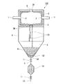
図1は、本実施形態として示される一般的な石炭ガス化装置100であって、ライン(図示略)より微粉炭(石炭)を搬送し、ライン1を用いてガス化剤(酸素含有ガス等)をバーナ2より高温の加圧されたガス化炉3内に噴入して部分酸化させる構成であり、このガス化炉3で生じる生成ガスGを上部開口3Aから排出する。
なお、ガス化炉3の上部開口3Aの上方には、該ガス化炉3内で生成したガス化ガス中に水素を投入して水素化熱分解によりガス、オイル、及びチャーを生成する図示しない改質炉が連設されている。
An embodiment of the present invention will be described with reference to FIGS.
FIG. 1 shows a
Above the
また、ガス化炉3での部分酸化に伴い、副産物として石炭中の灰分がスラグとなってガス化炉3の内壁にスラグコーティング(符号Sで示す)されるとともに、その一部は溶融スラグS1になって排出される。
ここで、スラグコーティングSを形成する溶融スラグS1は、100vol%液相である場合もあるし、固相が混ざって液相比率が低下する場合もあるが、以下、100vol%液相である場合の他、固相が混ざって液相比率が100%以下となる場合も「溶融スラグS1」として説明する。
Further, along with the partial oxidation in the gasification furnace 3, the ash content in the coal becomes a slag as a by-product and is slag-coated on the inner wall of the gasification furnace 3 (indicated by a symbol S), and a part of the molten slag S1 Will be discharged.
Here, the molten slag S1 forming the slag coating S may be in a 100 vol% liquid phase, or the solid phase may be mixed and the liquid phase ratio may be reduced. In addition, the case where the solid phase is mixed and the liquid phase ratio becomes 100% or less will be described as “molten slag S1”.
前記ガス化炉3は、その下部に設けられたスラグタップ排出孔3Bを経由して、内部で形成される溶融スラグS1が排出かつ滴下されるものであって、スラグタップ排出孔3Bから排出された溶融スラグS1は、スラグ冷却部4を滴下する間に冷却された後、スラグ水砕部5に貯留される。
このスラグ水砕部5は内部にスラグ冷却水6が貯留されるものであって、溶融スラグS1を水砕・急冷却して水砕スラグS2とした後、下部のスラグ排出孔5Aより排出する。
The gasification furnace 3 is for discharging and dropping molten slag S1 formed inside through a slag
The slag water granulating
前記スラグ水砕部5の下部に位置するスラグ排出孔5Aには、弁7を有する連結管8が接続されており、該連結管8を通じて、スラグ水砕部5から排出された水砕スラグS2がスラグロックホッパ10に送られる。
このスラグロックホッパ10は、例えば、水砕スラグS2を一定時間貯留して、スラグ沈殿させるものであって、一定時間が経過した後に、弁11を有する連結管12を経由して水砕スラグS2を系外に取り出すようにしている。
A connecting
The slag lock hopper 10 stores, for example, the granulated slag S2 for a certain period of time and causes the slag to settle. After a certain period of time has elapsed, the granulated slag S2 passes through the connecting
次に、炉壁のスラグコーティングSを適正量に維持することが可能なスラグ組成について説明する。
石炭ガス化装置100に使用する原炭は、その組成により決定される溶融温度(三成分系状態図により示される)に基づき100vol%液相となるものであるが、このとき、炉壁のスラグコーティングSを適正量に維持するという観点からすれば、液相率が100vol%である必要がない。
ここで、図2の溶融スラグの温度と溶融スラグの液相率との関係を示すグラフを参照して分かるように、「○」「△」で示される「A炭」、「◆」「◇」で示される「B炭」(A炭とは種類が異なる)の全てが、石炭の種類によらず溶融スラグの温度を上昇させることで、液相率が100vol%となる。なお上記「A炭」はアダロ炭であり、「B炭」はタニトハルム炭である。
Next, the slag composition capable of maintaining an appropriate amount of the slag coating S on the furnace wall will be described.
The raw coal used in the
Here, as can be understood with reference to the graph showing the relationship between the temperature of the molten slag and the liquid phase ratio of the molten slag in FIG. 2, “A charcoal”, “◆”, “◇” indicated by “◯” and “△”. "B charcoal" (a type different from A coal) indicated by "" raises the temperature of the molten slag regardless of the type of coal, and the liquid phase ratio becomes 100 vol%. The “A charcoal” is Adalo charcoal, and the “B charcoal” is Tanitoharum charcoal.
図2より、溶融スラグの液相率が65vol%以上(固相率が35vol%以下)の場合は、温度と液相率の関係が緩やかに変化するが、液相率が65vol%より小さくなる(固相率が35vol%を超える)場合は、温度と液相率の関係が急激に変化し、少しの温度低下で急激に固化し、石炭ガス化運転が困難となる。 From FIG. 2, when the liquid phase ratio of the molten slag is 65 vol% or more (the solid phase ratio is 35 vol% or less), the relationship between the temperature and the liquid phase ratio changes gradually, but the liquid phase ratio is smaller than 65 vol%. In the case where the solid phase ratio exceeds 35 vol%, the relationship between the temperature and the liquid phase ratio changes abruptly, solidifies rapidly with a slight temperature drop, and the coal gasification operation becomes difficult.
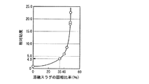
この点を示したのが、溶融スラグの固相率と粘度との関係を示した図3であり、森−乙竹の式による相対粘度がよく当てはまる。この図を参照して分かるように、溶融スラグの固相率が上昇すると、スラグの相対粘度も上昇する関係があることが示されている。そして、図3のグラフに示すように、溶融スラグの固相率が35vol%を超えると相対粘度が4を超えるようになり(元の粘度の4倍)、急激に流動性が悪くなることが確認される。なお、液相率100vol%の溶融スラグにおける固有粘度は、組成にもよるが、例えば1450℃において1.68〜22.7Pa・s、1500℃において1.15〜13.1Pa・sとなっている。
このことから、温度と液相率の関係が緩やかに変化する、溶融スラグの液相率が65vol%以上の範囲(固相率が35vol%以下)に保つことにより、炉壁のスラグコーティングSを適正量に維持して、石炭ガス化運転を良好に行うことができると判断される。さらに、石炭ガス化運転を更に良好に行うためには、液相率65vol%以上の範囲において、粘度の変化の少ない液相率を80vol%以上に(固相率を20vol%以下に)することがさらに適当であると、判断される。さらにまた、固相率は15vol%以下であることが一層好ましい。
This point is shown in FIG. 3 showing the relationship between the solid phase ratio and the viscosity of the molten slag, and the relative viscosity according to the Mori-Otsutake equation is well applied. As can be seen with reference to this figure, it is shown that when the solid phase ratio of the molten slag increases, the relative viscosity of the slag also increases. As shown in the graph of FIG. 3, when the solid phase ratio of the molten slag exceeds 35 vol%, the relative viscosity exceeds 4 (4 times the original viscosity), and the fluidity may deteriorate rapidly. It is confirmed. The intrinsic viscosity of the molten slag having a liquid phase ratio of 100 vol% is, for example, 1.68 to 22.7 Pa · s at 1450 ° C. and 1.15 to 13.1 Pa · s at 1500 ° C. Yes.
From this, the slag coating S on the furnace wall is maintained by maintaining the liquid slag liquid phase ratio in a range of 65 vol% or more (solid phase ratio is 35 vol% or less) where the relationship between the temperature and the liquid phase ratio changes gradually. It is determined that the coal gasification operation can be carried out satisfactorily while maintaining an appropriate amount. Furthermore, in order to perform the coal gasification operation more satisfactorily, the liquid phase ratio with a small change in viscosity is set to 80 vol% or more (solid phase ratio is set to 20 vol% or less) in the range of the liquid phase ratio of 65 vol% or more. Is determined to be more appropriate. Furthermore, the solid phase ratio is more preferably 15 vol% or less.
なお、溶融スラグの固相率の制御は、例えばガス化炉3内の温度を制御することにより行うことができる。
すなわち溶融スラグの組成は、ガス化炉3内に投入する石炭の成分に依存することから、所定の成分からなる石炭をガス化炉3内に投入したときに生成される溶融スラグの温度と、この溶融スラグの液相/固相率と、の相関関係は、例えば検証試験などを行うことにより、図2に示すグラフのように予め求めておくことができる。そして、この相関関係に基づき、ガス化炉3内の温度を、例えば溶融スラグの固相率が35vol%以下になるような範囲(例えば、図2に示す「△」のA端では、およそ1240℃以上の範囲)にすることにより、溶融スラグの固相率を制御することができる。
The solid phase ratio of the molten slag can be controlled by controlling the temperature in the gasification furnace 3, for example.
That is, since the composition of the molten slag depends on the components of the coal to be input into the gasification furnace 3, the temperature of the molten slag that is generated when coal comprising a predetermined component is input into the gasification furnace 3, The correlation between the liquid phase / solid phase ratio of the molten slag can be obtained in advance as shown in the graph of FIG. 2, for example, by performing a verification test or the like. Based on this correlation, the temperature in the gasification furnace 3 is, for example, in a range where the solid phase ratio of the molten slag is 35 vol% or less (for example, approximately 1240 at the A end of “Δ” shown in FIG. 2). By setting the temperature within the range of not lower than ° C., the solid phase ratio of the molten slag can be controlled.
また、ガス化炉3内の溶融スラグにおける固相比率は、公知の方法を用いて算出することが可能であり、例えば溶融スラグのスラグ組成(灰組成)、および液相の生成自由エネルギーの推定と化合物の熱力学データ基づいて、平衡状態図を作成可能なソフトウェアにより算出すること等ができる。 The solid phase ratio in the molten slag in the gasification furnace 3 can be calculated using a known method. For example, the slag composition (ash composition) of the molten slag and the estimation of the free energy of formation of the liquid phase Based on the thermodynamic data of the compound and the compound, it can be calculated by software capable of creating an equilibrium diagram.
以上詳細に説明したように本発明の本実施形態に係る石炭ガス化方法によれば、ガス化炉3で形成される溶融スラグの固相比率を35vol%、好ましくは20vol%以下となる範囲で固相分が含まれるようにガス化炉3内の温度を調整することにより、固相比率の上昇に伴って溶融スラグの粘度が緩やかに上昇し、これにより炉壁のスラグコーティングを適正量に維持することができる。 As described above in detail, according to the coal gasification method according to the present embodiment of the present invention, the solid phase ratio of the molten slag formed in the gasification furnace 3 is 35 vol%, preferably 20 vol% or less. By adjusting the temperature in the gasification furnace 3 so that the solid phase content is included, the viscosity of the molten slag gradually rises as the solid phase ratio increases, thereby making the slag coating on the furnace wall an appropriate amount Can be maintained.
なお、上記実施形態では、ガス化炉3で形成される溶融スラグの固相比率を35vol%以下となる範囲で固相分が含まれるようにガス化炉3内の温度を調整することを必須とするが、これに加えて、繊維状スラグの発生割合を低く抑えるために、スラグの塩基度を上昇させる原炭の成分調整を行っても良い。 In the above embodiment, it is essential to adjust the temperature in the gasification furnace 3 so that the solid phase content is included in the range where the solid phase ratio of the molten slag formed in the gasification furnace 3 is 35 vol% or less. However, in addition to this, in order to keep the generation rate of fibrous slag low, the raw coal components may be adjusted to increase the basicity of the slag.
また、上記実施形態では、ガス化炉3及び改質炉からなる二室二段炉を使用したが、これに限定されず、例えば1つの炉において、ガス化ガスを生成と、水素化熱分解とを共に行うガス化炉を有する石炭ガス化装置などにおいて、ガス化炉で形成される溶融スラグの固相比率が35vol%以下となるようにガス化炉内の温度を調整しても良い。 Moreover, in the said embodiment, although the two-chamber two-stage furnace which consists of the gasification furnace 3 and a reforming furnace was used, it is not limited to this, For example, in one furnace, gasification gas is produced | generated, and hydropyrolysis In a coal gasifier having a gasification furnace that performs both of the above, the temperature in the gasification furnace may be adjusted so that the solid phase ratio of the molten slag formed in the gasification furnace is 35 vol% or less.
以上、本発明の実施形態について図面を参照して詳述したが、具体的な構成はこの実施形態に限られるものではなく、本発明の要旨を逸脱しない範囲の設計変更等も含まれる。 As mentioned above, although embodiment of this invention was explained in full detail with reference to drawings, the concrete structure is not restricted to this embodiment, The design change etc. of the range which does not deviate from the summary of this invention are included.
本発明は、石炭を部分酸化してガス化するガス化炉を有する石炭ガス化装置における石炭ガス化方法に関する。 The present invention relates to a coal gasification method in a coal gasification apparatus having a gasification furnace for partially oxidizing and gasifying coal.
3 ガス化炉
100 石炭ガス化装置
S スラグコーティング
3
Claims (2)
前記ガス化炉で形成される溶融スラグの固相比率が35vol%以下となる範囲で固相分が含まれるように前記ガス化炉内の温度を調整することを特徴とする石炭ガス化方法。 A coal gasification method in a coal gasifier having a gasification furnace for partially oxidizing and gasifying coal,
A coal gasification method, wherein the temperature in the gasification furnace is adjusted so that the solid phase content is included in a range where the solid phase ratio of the molten slag formed in the gasification furnace is 35 vol% or less.
Priority Applications (4)
| Application Number | Priority Date | Filing Date | Title |
|---|---|---|---|
| JP2011056945A JP5674517B2 (en) | 2011-03-15 | 2011-03-15 | Coal gasification method |
| AU2012227466A AU2012227466B2 (en) | 2011-03-15 | 2012-03-08 | Coal gasification method |
| PCT/JP2012/055932 WO2012124590A1 (en) | 2011-03-15 | 2012-03-08 | Coal gasification method |
| CN201280013016.5A CN103429714B (en) | 2011-03-15 | 2012-03-08 | Coal gasification method |
Applications Claiming Priority (1)
| Application Number | Priority Date | Filing Date | Title |
|---|---|---|---|
| JP2011056945A JP5674517B2 (en) | 2011-03-15 | 2011-03-15 | Coal gasification method |
Publications (2)
| Publication Number | Publication Date |
|---|---|
| JP2012193247A true JP2012193247A (en) | 2012-10-11 |
| JP5674517B2 JP5674517B2 (en) | 2015-02-25 |
Family
ID=46830663
Family Applications (1)
| Application Number | Title | Priority Date | Filing Date |
|---|---|---|---|
| JP2011056945A Active JP5674517B2 (en) | 2011-03-15 | 2011-03-15 | Coal gasification method |
Country Status (4)
| Country | Link |
|---|---|
| JP (1) | JP5674517B2 (en) |
| CN (1) | CN103429714B (en) |
| AU (1) | AU2012227466B2 (en) |
| WO (1) | WO2012124590A1 (en) |
Families Citing this family (1)
| Publication number | Priority date | Publication date | Assignee | Title |
|---|---|---|---|---|
| JP6380145B2 (en) * | 2015-02-06 | 2018-08-29 | 新日鐵住金株式会社 | Slag product material and manufacturing method thereof |
Citations (5)
| Publication number | Priority date | Publication date | Assignee | Title |
|---|---|---|---|---|
| JPS59232173A (en) * | 1983-06-01 | 1984-12-26 | コンバツシヨン・エンヂニアリング・インコ−ポレ−テツド | Solid fuel gasifying device |
| JPH0414157B2 (en) * | 1983-05-11 | 1992-03-11 | Hitachi Seisakusho Kk | |
| JPH0427279B2 (en) * | 1983-12-29 | 1992-05-11 | Babcock Hitachi Kk | |
| JPH09111256A (en) * | 1995-10-18 | 1997-04-28 | Sekitan Riyou Sogo Center | Device for gasifying coal |
| JPH10306285A (en) * | 1997-05-07 | 1998-11-17 | Babcock Hitachi Kk | Oven floor structure of coal-gasifying oven |
Family Cites Families (6)
| Publication number | Priority date | Publication date | Assignee | Title |
|---|---|---|---|---|
| JPH0765793B2 (en) * | 1989-06-08 | 1995-07-19 | ダイキン工業株式会社 | Multi-type air conditioner |
| JP2652068B2 (en) * | 1989-07-27 | 1997-09-10 | キヤノン株式会社 | Decal mechanism and recording apparatus using the decurl mechanism |
| DE69403091T2 (en) * | 1993-11-12 | 1997-10-09 | Shell Int Research | METHOD FOR GASIFYING A PETROLEUM COOKING INSERT |
| US5545238A (en) * | 1994-12-29 | 1996-08-13 | Texaco Inc. | Method of monitoring slag removal during controlled oxidation of a partial oxidation reactor |
| CN101392191B (en) * | 2008-10-15 | 2011-11-23 | 合肥工业大学 | Two-stage dry coal pulverized entrained bed gasifier |
| CN101885989B (en) * | 2010-07-16 | 2013-02-13 | 浙江大学 | Coal gasification device capable of controlling continuous coal gasification |
-
2011
- 2011-03-15 JP JP2011056945A patent/JP5674517B2/en active Active
-
2012
- 2012-03-08 AU AU2012227466A patent/AU2012227466B2/en active Active
- 2012-03-08 CN CN201280013016.5A patent/CN103429714B/en active Active
- 2012-03-08 WO PCT/JP2012/055932 patent/WO2012124590A1/en not_active Ceased
Patent Citations (5)
| Publication number | Priority date | Publication date | Assignee | Title |
|---|---|---|---|---|
| JPH0414157B2 (en) * | 1983-05-11 | 1992-03-11 | Hitachi Seisakusho Kk | |
| JPS59232173A (en) * | 1983-06-01 | 1984-12-26 | コンバツシヨン・エンヂニアリング・インコ−ポレ−テツド | Solid fuel gasifying device |
| JPH0427279B2 (en) * | 1983-12-29 | 1992-05-11 | Babcock Hitachi Kk | |
| JPH09111256A (en) * | 1995-10-18 | 1997-04-28 | Sekitan Riyou Sogo Center | Device for gasifying coal |
| JPH10306285A (en) * | 1997-05-07 | 1998-11-17 | Babcock Hitachi Kk | Oven floor structure of coal-gasifying oven |
Also Published As
| Publication number | Publication date |
|---|---|
| CN103429714B (en) | 2015-04-22 |
| JP5674517B2 (en) | 2015-02-25 |
| AU2012227466A1 (en) | 2013-10-31 |
| AU2012227466B2 (en) | 2016-06-16 |
| WO2012124590A1 (en) | 2012-09-20 |
| CN103429714A (en) | 2013-12-04 |
Similar Documents
| Publication | Publication Date | Title |
|---|---|---|
| Gong et al. | Pilot-scale comparison investigation of different entrained-flow gasification technologies and prediction on industrial-scale gasification performance | |
| US20080166291A1 (en) | Reactor and process for the continuous production of hydrogen based on steam oxidation of molten iron | |
| JP6229863B2 (en) | Oxygen blast furnace operation method | |
| JP2011514240A (en) | Gas transfer in a multi-metal bath reactor. | |
| CN101448962B (en) | Method for manufacturing molten irons by injecting a hydrocarbon gas and apparatus for manufacturing molten irons using the same | |
| Zhang et al. | Mechanism and interaction of alkaline-earth metal migration induced ash transformation and carbon structure evolution for single coal particle high-temperature gasification | |
| JP5674517B2 (en) | Coal gasification method | |
| JP3410100B2 (en) | Gasification of petroleum coke feedstock | |
| Zhang et al. | Micro-scale study of mineral transformation and coverability at single coal char particle surface during high-temperature gasification process | |
| JP5745288B2 (en) | Coal gasification method in coal gasifier | |
| Park et al. | Slagging of petroleum coke ash using Korean anthracites | |
| EP2788515A1 (en) | Starting a smelting process | |
| CN100404652C (en) | Staged gasifier for coal and coke gasification | |
| WO2013014995A1 (en) | Method for producing coal gas and method for producing methane | |
| US8703021B1 (en) | Basic refractory and slag management for petcoke carbon feedstock in gasifiers | |
| CN117946770A (en) | Method for online regulation and control of viscosity-temperature characteristics of coal ash slag | |
| JPH0880434A (en) | Oxidizer injection for improvement of oxidation control | |
| WO2012124604A1 (en) | Slag form adjustment method | |
| JP2007231203A (en) | Gasification method for carbonaceous raw materials | |
| KR101235252B1 (en) | Method for manufacturing molten irons by injecting a hydrocarbon gas and apparatus for manufacturing molten irons using the same | |
| KR100803983B1 (en) | Molten iron manufacturing equipment and molten iron manufacturing method | |
| JP4759977B2 (en) | Blast furnace operation method | |
| JP2025127761A (en) | Molten iron manufacturing method | |
| JP2003096472A (en) | Method for preventing slag adhesion in two step entrained bed gasification furnace | |
| KR101405013B1 (en) | Entrained flow gasification reactor |
Legal Events
| Date | Code | Title | Description |
|---|---|---|---|
| A621 | Written request for application examination |
Free format text: JAPANESE INTERMEDIATE CODE: A621 Effective date: 20131107 |
|
| A131 | Notification of reasons for refusal |
Free format text: JAPANESE INTERMEDIATE CODE: A131 Effective date: 20140930 |
|
| A521 | Request for written amendment filed |
Free format text: JAPANESE INTERMEDIATE CODE: A523 Effective date: 20141104 |
|
| TRDD | Decision of grant or rejection written | ||
| A01 | Written decision to grant a patent or to grant a registration (utility model) |
Free format text: JAPANESE INTERMEDIATE CODE: A01 Effective date: 20141125 |
|
| A61 | First payment of annual fees (during grant procedure) |
Free format text: JAPANESE INTERMEDIATE CODE: A61 Effective date: 20141222 |
|
| R150 | Certificate of patent or registration of utility model |
Ref document number: 5674517 Country of ref document: JP Free format text: JAPANESE INTERMEDIATE CODE: R150 |
|
| R250 | Receipt of annual fees |
Free format text: JAPANESE INTERMEDIATE CODE: R250 |
|
| R250 | Receipt of annual fees |
Free format text: JAPANESE INTERMEDIATE CODE: R250 |
|
| S533 | Written request for registration of change of name |
Free format text: JAPANESE INTERMEDIATE CODE: R313533 |
|
| R350 | Written notification of registration of transfer |
Free format text: JAPANESE INTERMEDIATE CODE: R350 |
|
| R250 | Receipt of annual fees |
Free format text: JAPANESE INTERMEDIATE CODE: R250 |
|
| R250 | Receipt of annual fees |
Free format text: JAPANESE INTERMEDIATE CODE: R250 |
|
| R250 | Receipt of annual fees |
Free format text: JAPANESE INTERMEDIATE CODE: R250 |
|
| R250 | Receipt of annual fees |
Free format text: JAPANESE INTERMEDIATE CODE: R250 |
|
| R250 | Receipt of annual fees |
Free format text: JAPANESE INTERMEDIATE CODE: R250 |
|
| R250 | Receipt of annual fees |
Free format text: JAPANESE INTERMEDIATE CODE: R250 |
|
| R250 | Receipt of annual fees |
Free format text: JAPANESE INTERMEDIATE CODE: R250 |