JP2012193577A - Reinforcing method of existent covering and reinforcing apparatus - Google Patents
Reinforcing method of existent covering and reinforcing apparatus Download PDFInfo
- Publication number
- JP2012193577A JP2012193577A JP2011059541A JP2011059541A JP2012193577A JP 2012193577 A JP2012193577 A JP 2012193577A JP 2011059541 A JP2011059541 A JP 2011059541A JP 2011059541 A JP2011059541 A JP 2011059541A JP 2012193577 A JP2012193577 A JP 2012193577A
- Authority
- JP
- Japan
- Prior art keywords
- arc
- existing lining
- reinforcing
- jack
- interval
- Prior art date
- Legal status (The legal status is an assumption and is not a legal conclusion. Google has not performed a legal analysis and makes no representation as to the accuracy of the status listed.)
- Granted
Links
Images


Landscapes
- Lining And Supports For Tunnels (AREA)
Abstract
【課題】断面円形の既設覆工を内側から補強する補強方法と補強装置に関し、補強後の覆工内に利用障害となる補強ユニットも存在せず、既設覆工に効果的に内側から力を付与して既設覆工を外側に押し出してその変形を緩和でき、既設覆工を介して地山に押し出し力を付与して既設覆工を効果的に補強できる既設覆工の補強方法と補強装置を提供する。
【解決手段】断面円形の既設覆工Fの内面の周方向に複数の弧状ブロック1を間隔を置いて配設し、間隔内にジャッキ3を配するステップ、各ジャッキ3を張り出させて間隔を広げながら周方向の軸力を弧状ブロック1に付与するステップ、広げられた間隔を保持する間隔保持材を間隔内に配し、ジャッキ3を取り外してジャッキ反力を間隔保持材に受け替え、周方向に配設された複数の弧状ブロック1と複数の間隔保持材からなる補強リングを形成するステップ、からなる。
【選択図】図3The present invention relates to a reinforcing method and a reinforcing device that reinforce an existing lining with a circular cross section from the inside, and there is no reinforcing unit that obstructs use in the lining after reinforcement, and the existing lining is effectively applied with force from the inside. A method and apparatus for reinforcing an existing lining, which can be applied to extrude the existing lining to the outside to mitigate its deformation, and can effectively reinforce the existing lining by applying an extrusion force to the ground via the existing lining. I will provide a.
A step of arranging a plurality of arc-shaped blocks 1 at intervals in the circumferential direction of the inner surface of an existing lining F having a circular cross section, and arranging jacks 3 within the intervals, each jack 3 projecting and spaced apart. A step of applying a circumferential axial force to the arc-shaped block 1 while spreading the gap, arranging a gap holding material for holding the widened gap in the gap, removing the jack 3 and replacing the jack reaction force with the gap holding material, Forming a reinforcing ring comprising a plurality of arc-shaped blocks 1 arranged in the circumferential direction and a plurality of spacing members.
[Selection] Figure 3
Description
本発明は、地下トンネルの既設覆工をその内側から補強する既設覆工の補強方法と補強装置に関するものである。 The present invention relates to an existing lining reinforcing method and a reinforcing device for reinforcing an existing lining of an underground tunnel from the inside thereof.
首都圏をはじめとする都市部においては、密集した建物の間に幹線道路や鉄道路線が設けられ、場所によっては高速道等が立体交差するなどしてその地上空間が利用されており、したがって、新たな幹線道路やインフラ設備用の空きスペースを地上に求めることがほぼ不可能な状況となっている。 In urban areas such as the Tokyo metropolitan area, there are trunk roads and railway lines between dense buildings, and depending on the location, the ground space is used by three-dimensional intersections of expressways, etc. It is almost impossible to find free space on the ground for new main roads and infrastructure facilities.
そこで、上記する空きスペースの確保を地下に求め、地下空間を有効に利用しながら、地下道や共同溝、送水・排水管路や電力ケーブル、ガス配管などが収容された洞道などの地下トンネルが施工されている。 Therefore, there is an underground tunnel such as a cave that contains underground passages, common grooves, water supply / drainage pipes, power cables, gas pipes, etc. It is being constructed.
この地下トンネルは、地上交通を占有し、土留め支保工にて確保された開削空間内に筐体を施工する開削工法や、シールド掘進機を利用して当該掘進機で比較的軟弱な地盤を支保しながらセグメントをリング状に組み付け、これに反力を取って掘進機の掘進を図りながらシールドトンネルを施工するシールド工法、さらには、たとえば立坑にある推進機から地盤内に推進管を押出してこれを繋げていく推進工法など、その施工方法は多岐に亘る。 This underground tunnel occupies ground traffic and uses the excavation method that constructs the housing in the excavation space secured by the earth retaining support, and the excavator uses the excavator to create a relatively soft ground. Assembling the segments in a ring shape while supporting them, taking a reaction force against them, constructing a shield tunnel while digging the excavator, and, for example, by pushing a propulsion pipe from a propeller in a shaft into the ground There are a wide variety of construction methods, such as the propulsion method that connects them.
ところで、地下空間の利用の歴史は比較的古く、都市部においては既に数十年の供用期間を経たトンネルも存在している。このような供用期間の長い地下トンネルでは、セグメント等の構成部材そのものの経年劣化のほか、周辺地盤における新たなトンネルの構築や地下水位の変動などによって作用荷重が変化し、これに伴って構造耐力が不足したり過度の変形が生じてクラックが誘発され、漏水に至るといった問題などがある。 By the way, the history of use of underground space is relatively old, and there are tunnels that have already been in service for several decades in urban areas. In such underground tunnels with a long service period, in addition to the aging of the components such as segments, the working load changes due to the construction of new tunnels in the surrounding ground and the fluctuation of the groundwater level. There are problems such as lack of water and excessive deformation to induce cracks and water leakage.
施工されて20年以上を経た地下トンネルの中には、許容値を超える大きな変形が観測されている既設トンネルも存在している。このような大きな変形の主たる原因は定かではないものの、周辺地盤における再開発工事による作用土圧の変動や長期的な地下水位の変動が主たる要因の一つであろうとの推察がなされている。 Among underground tunnels that have been constructed for more than 20 years, there are existing tunnels where large deformation exceeding the allowable value has been observed. Although the main cause of such a large deformation is not clear, it has been speculated that one of the main factors is a change in the earth pressure due to redevelopment work in the surrounding ground and a long-term change in the groundwater level.
このように、補強を要する地下トンネルを構成する既設覆工の補強方法は多岐に亘るが、その中でも既設覆工内で剛性柱を十字状や放射状に組み立て、剛性柱のたとえば端部にジャッキを設け、これを張り出させて既設覆工を外側(地山側)に押し出して変形した既設トンネルを補強する方法がある。この補強方法では、ジャッキ反力によって強制的に変形が緩和された既設覆工の状態を維持するべく、十字状等に組み付けられた剛性柱の組付け体が既設覆工内に残置されることになる。 In this way, there are a variety of methods for reinforcing existing linings that make up underground tunnels that require reinforcement, but among them, rigid columns are assembled in a cross or radial shape within the existing lining, and jacks are attached to the ends of the rigid columns, for example. There is a method to reinforce an existing tunnel which is provided and extended to push the existing lining to the outside (natural ground side). In this reinforcement method, in order to maintain the state of the existing lining whose deformation has been forcibly relaxed by the reaction force of the jack, the assembly of rigid columns assembled in a cross shape or the like is left in the existing lining. become.
このように既設覆工内に十字状等に組み付けられた剛性柱の組付け体が残置されてしまうと、これが既設覆工内の供用にとって大きな障害となり、その利用態様が制限されるといった大きな課題が生じてしまう。 If the assembly of rigid pillars assembled in a cross shape or the like is left in the existing lining as described above, this is a big problem for the use in the existing lining and its usage mode is limited. Will occur.
そこで、特許文献1には、既設トンネルの内周とほぼ同形状の補強材を周方向に分割した多数の補強セグメントを準備し、この補強セグメントを下段から一段ずつ設置して背面にグラウトを注入し、これを周方向さらには既設覆工の軸方向に繰り返してその補強をおこなう方法が開示されている。
Therefore,
この補強方法によれば、既設覆工内部に構築された補強セグメントリングが既設覆工内部を利用する上で障害とならないことから、上記課題を解消することができる。 According to this reinforcing method, the reinforcing segment ring built inside the existing lining does not become an obstacle to using the existing lining, so that the above problem can be solved.
しかしながら、特許文献1で開示される補強方法は、補強セグメントリングが上記する十字状等に組み付けられた剛性柱の組付け体のように既設覆工に力を付与するものでなく、既設覆工と補強セグメントリングはグラウトを介して間接的に併設されているに過ぎないことから既設覆工の変形緩和効果は極めて低い。
However, the reinforcing method disclosed in
そのため、既設覆工の変形を緩和し、当該変形に起因する内部応力を低減して既設覆工の耐力回復を図ることができないことに加えて、外力によって既設覆工の変形が一層進行して破損等した際には、外力を補給セグメントリングのみで支持する必要が生じることは必至である。 Therefore, in addition to relieving the deformation of the existing lining and reducing the internal stress due to the deformation, it is not possible to recover the strength of the existing lining, and the deformation of the existing lining is further advanced by external force. In the event of breakage or the like, it is inevitable that external force needs to be supported only by the supplemental segment ring.
本発明は上記する問題に鑑みてなされたものであり、断面が円形もしくは略円形の既設覆工をその内側から補強する補強方法に関し、補強後の覆工内に利用障害となる補強ユニットも存在せず、かつ、既設覆工に効果的に内側から力を付与して既設覆工を外側(径方向外側)に押し出してその変形を緩和させたり、既設覆工を介して地山に押し出し力を付与することで既設覆工を効果的に補強することのできる、既設覆工の補強方法と補強装置を提供することを目的としている。 The present invention has been made in view of the above-described problems, and relates to a reinforcing method for reinforcing an existing lining having a circular or substantially circular cross section from the inside thereof, and there is also a reinforcing unit that obstructs use in the lining after reinforcement. Without applying force to the existing lining effectively from the inside and pushing the existing lining outward (radially outward) to ease the deformation, or pushing force to the ground via the existing lining It is an object of the present invention to provide a reinforcing method and a reinforcing device for an existing lining that can effectively reinforce the existing lining.
前記目的を達成すべく、本発明による既設覆工の補強方法は、地下トンネルにおける断面が円形もしくは略円形の既設覆工の内面の周方向に、複数の弧状ブロックを間隔を置いて配設するとともに、該間隔内にジャッキを配する第1のステップ、複数のジャッキを張り出させてそれぞれの弧状ブロック間の間隔を広げながら周方向の軸力をそれぞれの弧状ブロックに付与する第2のステップ、広げられた前記間隔を保持する間隔保持材を複数の該間隔内に配し、ジャッキを該間隔から取り外してジャッキ反力を間隔保持材に受け替えて、少なくとも周方向に配設された複数の弧状ブロックと複数の間隔保持材からなる補強リングを形成する第3のステップ、からなるものである。 In order to achieve the above-mentioned object, according to the method of reinforcing an existing lining according to the present invention, a plurality of arc-shaped blocks are arranged at intervals in the circumferential direction of the inner surface of an existing lining having a circular or substantially circular cross section in an underground tunnel. And a first step of arranging a jack within the interval, and a second step of applying a circumferential axial force to each arc-shaped block while extending a plurality of jacks to widen the interval between the arc-shaped blocks. A plurality of spacing members arranged at least in the circumferential direction by disposing a spacing member that holds the widened spacing in the plurality of spacings, removing the jack from the spacing and replacing the jack reaction force with the spacing member; And a third step of forming a reinforcing ring comprising a plurality of spacing members.
本発明の既設覆工の補強方法は、既述する従来技術のように既設覆工の内側から剛性柱のような軸部材を利用してその軸方向に力を生じさせて既設覆工に付与する技術思想に代わり、断面円形等の既設覆工の内面に周方向に軸力を生じさせることのできる補強リングを構築し、この補強リングに軸力を作用させてその径を拡大させ、補強リングの拡径の過程で既設覆工に地山側へ押し出す力を付与させるという新規な技術思想を具現化したものである。 The reinforcing method of the existing lining of the present invention is applied to the existing lining by generating a force in the axial direction using a shaft member such as a rigid column from the inside of the existing lining as in the prior art described above. Instead of the technical idea, a reinforcing ring that can generate an axial force in the circumferential direction on the inner surface of the existing lining, such as a circular cross section, is constructed, and the diameter is increased by applying an axial force to the reinforcing ring to reinforce it. It embodies a new technical idea that the existing lining is given a force that pushes it to the ground in the process of expanding the diameter of the ring.
ここで、補強対象である既設覆工からなる地下トンネルは、セグメントリングを周方向およびトンネル軸方向(既設覆工の軸方向)に組み付けてなるシールドトンネルや推進管をトンネル軸方向に組み付けてなる推進トンネルなどのトンネル全般が対象であり、地下道や共同溝、送水・排水管路や電力ケーブル、ガス配管などが収容された洞道等に供されている既設トンネルの全般を含むものである。 Here, the underground tunnel consisting of the existing lining to be reinforced is constructed by assembling a shield tunnel or propulsion pipe with the segment ring assembled in the circumferential direction and the tunnel axial direction (axial direction of the existing lining) in the tunnel axial direction. It covers tunnels such as propulsion tunnels in general, and includes all existing tunnels that are provided in underground passages, joint grooves, water supply / drainage pipes, power cables, gas pipes, etc.
さらに、本発明の補強方法は、その補強対象となる地下トンネル(既設覆工)の断面が円形もしくは略円形(楕円形、上半と下半で曲率が異なる形状など)のものを補強対象としている。その理由は、本発明の補強方法が、補強リングを構成する複数の弧状ブロックに対して隣接する弧状ブロック間に配されたジャッキの張り出しによって軸力を付与し、周方向の軸力によって径方向(もしくは法線方向)の力を生じさせてこれを既設覆工に付与するものだからである。 Furthermore, in the reinforcing method of the present invention, an underground tunnel (existing lining) to be reinforced has a circular or substantially circular cross section (an ellipse, a shape having different curvatures in the upper half and the lower half, etc.). Yes. The reason is that the reinforcing method of the present invention applies axial force to the plurality of arc-shaped blocks constituting the reinforcing ring by the extension of jacks arranged between adjacent arc-shaped blocks, and the radial direction by the circumferential axial force. This is because a force in the (or normal direction) is generated and applied to the existing lining.
第1のステップでは、既設覆工の内面の周方向に、複数の弧状ブロックを間隔を置いて配設するとともに、該間隔内にジャッキを配する。たとえば、既設覆工内を自走するエレクタ装置等が搭載された仮受け台車等を利用し、既設覆工の周方向に所定間隔で複数の弧状ブロックを仮受けし、さらに、各間隔内にジャッキを配して仮受けする。 In the first step, a plurality of arc-shaped blocks are arranged at intervals in the circumferential direction of the inner surface of the existing lining, and jacks are arranged within the intervals. For example, using a temporary receiving carriage equipped with an erector device that self-propels in the existing lining, a plurality of arc-shaped blocks are temporarily received at predetermined intervals in the circumferential direction of the existing lining, and further, within each interval Arrange a jack and provisionally.
ここで、「弧状ブロック」とは、既設覆工の長手方向に所定の幅を有し、所定の厚みを有し、さらには、補強リングの一部の円弧を成すコンクリート製セグメントや鋼製セグメントなどを意味しており、いわゆる二次覆工材としての所定の剛性を有する部材のことである。 Here, the “arc-shaped block” is a concrete segment or steel segment having a predetermined width in the longitudinal direction of the existing lining, a predetermined thickness, and further forming a partial arc of the reinforcing ring. It is a member having a predetermined rigidity as a so-called secondary lining material.
複数の弧状ブロックとジャッキを既設覆工の周方向に組み付けて仮受けさせたら、第2のステップとして各ジャッキを同期制御して対応する左右の弧状ブロックに同様の軸力を付与させる。 When a plurality of arc-shaped blocks and jacks are assembled and provisionally received in the circumferential direction of the existing lining, each jack is synchronously controlled as a second step to apply the same axial force to the corresponding left and right arc-shaped blocks.
ある程度の軸力が導入されたら、複数の弧状ブロックとジャッキは仮受けなしに自立的にリング形状を形成できるようになるので、この段階でエレクタ装置等による仮受けを解除する。この段階で、補強リングの前段となる中間補強リングが形成される。 When a certain axial force is introduced, the plurality of arc-shaped blocks and jacks can form a ring shape independently without provisional support, and at this stage, the provisional support by the elector device or the like is released. At this stage, an intermediate reinforcing ring that is a front stage of the reinforcing ring is formed.
各ジャッキの張り出し量を除々に大きくしていくことで、弧状ブロック間の間隔が大きくなり、各間隔が同期して大きくなっていく過程で中間補強リングが拡径していく。 By gradually increasing the protruding amount of each jack, the interval between the arc-shaped blocks increases, and the intermediate reinforcing ring expands in the process of increasing each interval in synchronization.
中間補強リングの拡径にともなって、中間補強リングの軸力に起因する径方向の力が既設覆工に作用し、既設覆工はこの力によって地山側へ押し出されることになる。そのため、既設覆工の一部が内側に変形している場合はこの変形を地山側へ押し出して当該変形を緩和することができ、この変形によって既設覆工内に生じていた内部応力を低減して既設覆工の耐力回復を図ることができる。 As the diameter of the intermediate reinforcing ring is increased, a radial force due to the axial force of the intermediate reinforcing ring acts on the existing lining, and the existing lining is pushed to the natural ground by this force. Therefore, when a part of the existing lining is deformed inward, this deformation can be pushed out to the natural ground side to mitigate the deformation, and this deformation reduces the internal stress generated in the existing lining. It is possible to restore the proof strength of the existing lining.
なお、構造力学的観点で言えば、断面円形(半径r)の既設覆工に地山から等分布荷重(q)が作用しているとした場合に、この等分布荷重によって既設覆工の周方向に生じる軸力N(圧縮力)は、N=qrの式で求められる。 In terms of structural mechanics, when an equally distributed load (q) is applied to the existing lining with a circular cross section (radius r) from the ground, the surrounding lining of the existing lining is affected by this evenly distributed load. The axial force N (compression force) generated in the direction is obtained by the equation N = qr.
したがって、中間補強リングを拡径しながらその軸力N’を増大させていくと、上記算定式より、軸力N’とその際の中間補強リングの断面(半径r’)に応じた等分布荷重q’がこの中間補強リングから既設覆工に付与され、さらにこの既設覆工を介して地山を既設覆工から押し出す方向(押し返す方向)に付与することができる。すなわち、この場合は、地山から既設覆工に作用している土圧や土水圧が中間補強リングから既設覆工に付与される押し出し力によって相殺されることになる。 Therefore, when the axial force N ′ is increased while expanding the diameter of the intermediate reinforcing ring, the distribution is equally distributed according to the axial force N ′ and the cross section (radius r ′) of the intermediate reinforcing ring at that time from the above calculation formula. The load q ′ can be applied from the intermediate reinforcing ring to the existing lining, and further, the ground can be applied in the direction of pushing out the natural ground from the existing lining (the direction of pushing back). That is, in this case, the earth pressure or earth water pressure acting on the existing lining from the natural ground is offset by the pushing force applied to the existing lining from the intermediate reinforcing ring.
また、将来的に既設覆工へ作用する土圧や土水圧等の荷重が増加した場合には、補強リングにて耐力回復が図られた(初期の耐力を具備する)既設覆工と補強リングからなる重ね梁として荷重に抵抗することもできる。 In addition, when the load such as earth pressure and earth water pressure acting on the existing lining increases in the future, the strength was restored by the reinforcing ring (having the initial proof strength) and the existing lining and the reinforcing ring. It is also possible to resist the load as a laminated beam consisting of
中間補強リングを所定径まで拡径したら、第3のステップとして、ジャッキが配されている間隔に対してこの間隔を保持する間隔保持材を挿入してこれでジャッキ反力を受け替えさせ、ジャッキを間隔から取り外すことにより、少なくとも周方向に配設された複数の弧状ブロックと複数の間隔保持材からなる補強リングを形成することができる。 Once the intermediate reinforcing ring has been expanded to a predetermined diameter, as a third step, an interval holding material that holds this interval is inserted with respect to the interval at which the jack is arranged, and the jack reaction force is exchanged with this. By removing from the interval, it is possible to form a reinforcing ring comprising at least a plurality of arc-shaped blocks arranged in the circumferential direction and a plurality of interval holding members.
ここで、前記弧状ブロックのうち、隣接する弧状ブロックに対向する端面は既設トンネル側からトンネル内側に傾斜したテーパー面を有し、前記間隔はその両側の2つのテーパー面によってトンネル内側に広がる断面視台形状を呈しており、前記間隔保持材は前記間隔と同じ断面視台形状の第1の楔となっているのが好ましい。 Here, of the arc-shaped blocks, an end surface facing an adjacent arc-shaped block has a tapered surface inclined from the existing tunnel side to the tunnel inner side, and the interval is a cross-sectional view extending to the tunnel inner side by two tapered surfaces on both sides thereof. It preferably has a trapezoidal shape, and the spacing member is preferably a first wedge having a trapezoidal cross-sectional shape that is the same as the spacing.
弧状ブロックの端面をテーパー面としておき、もって弧状ブロック間の間隔の断面形状をトンネル内側に広がる台形状としておくことで、同様に台形状をなす間隔保持材を間隔内に容易に挿入することができ、かつ、挿入後はこの間隔保持材が楔(第1の楔)となって軸力が生じている弧状ブロック同士の姿勢保持を保証することができる。 By setting the end face of the arc-shaped block as a tapered surface and the cross-sectional shape of the interval between the arc-shaped blocks as a trapezoidal shape extending inside the tunnel, a trapezoidal interval holding material can be easily inserted into the interval. In addition, after the insertion, the spacing member becomes a wedge (first wedge), and it is possible to ensure the posture maintenance of the arc-shaped blocks in which the axial force is generated.
なお、間隔保持材は、弧状ブロック間の間隔内に単に挿入することのほかにも、挿入後に弧状ブロックの端面と間隔保持材に跨るボルト等で緊結してもよい。 In addition to simply inserting the spacing member into the spacing between the arc-shaped blocks, the spacing member may be fastened with a bolt or the like straddling the end surface of the arc-shaped block and the spacing member after insertion.
また、前記弧状ブロックの前記テーパー面と前記ジャッキの間に角度調整用挿入具を配設し、該角度調整用挿入具の平坦面を該ジャッキが押圧する実施の形態であってもよい。 Further, an embodiment may be provided in which an angle adjusting insertion tool is disposed between the tapered surface of the arc-shaped block and the jack, and the jack presses the flat surface of the angle adjusting insertion tool.
弧状ブロックの端面がテーパー面となっているため、ジャッキの押し出し面をこのテーパー面に直接作用させる方法では、ジャッキからの押し出し力が弧状ブロックに効果的に伝達され難い。 Since the end surface of the arc-shaped block is a tapered surface, the pushing force from the jack is not effectively transmitted to the arc-shaped block by the method in which the pushing surface of the jack directly acts on the tapered surface.
そこで、ジャッキが弧状ブロックの端面を弧状ブロックの円弧方向に押し出すことができるように弧状ブロックの端面とジャッキの間に角度調整用挿入具を配設して平坦面(弧状ブロックの円弧方向に沿う方向と直交する面)を形成させておき、この角度調整用挿入具の平坦面をジャッキが押し出すようにしてやることで、ジャッキの押し出し力を効果的に弧状ブロックに付与することができる。なお、第3のステップでジャッキを取り外す際に、この角度調整用挿入具も取り外されることになる。 Therefore, an angle adjusting insertion tool is provided between the end surface of the arc-shaped block and the jack so that the jack can push the end surface of the arc-shaped block in the arc direction of the arc-shaped block, and a flat surface (along the arc direction of the arc-shaped block). A surface orthogonal to the direction) is formed, and the jack is pushed out of the flat surface of the angle adjusting insertion tool, whereby the pushing force of the jack can be effectively applied to the arc-shaped block. In addition, when removing a jack at a 3rd step, this insertion tool for angle adjustment will also be removed.
また、前記第1のステップでは、前記弧状ブロックの前記端面の略中央位置に前記ジャッキを配し、前記第3のステップでは、前記間隔保持材を前記端面における該ジャッキの両側に配す実施の形態であってもよい。 Further, in the first step, the jack is disposed at a substantially central position of the end surface of the arc-shaped block, and in the third step, the spacing member is disposed on both sides of the jack at the end surface. Form may be sufficient.
ジャッキ反力を間隔保持材に受け替えた際に、弧状ブロックの端面に軸力が一つの偏心位置のみに作用しないように、該端面の中央位置をジャッキで押し出すようにし、間隔保持材はこのジャッキの両側の2箇所(中央位置から左右同じオフセット位置)に配設するようにしておくことで、ジャッキ押し出し時に弧状ブロックに偏荷重が作用することもないし、ジャッキ反力を間隔保持材に受け替えた後に弧状ブロックに偏荷重が作用することもない。 When the jack reaction force is transferred to the spacing member, the central position of the end face is pushed out with a jack so that the axial force does not act on only one eccentric position on the end surface of the arc-shaped block. By arranging it at two locations on the both sides of the jack (the same offset position on the left and right from the center position), there will be no uneven load acting on the arc-shaped block when the jack is pushed out, and the jack reaction force will be received by the spacing retaining material. There is no possibility that an unbalanced load acts on the arc-shaped block after the replacement.
さらに、前記第3のステップでは、ジャッキを取り外した後に2つの前記間隔保持材の間に間詰め処理をおこなうのが好ましい。 Further, in the third step, it is preferable to perform a stuffing process between the two spacing members after removing the jack.
対向する弧状ブロックの端面と2つの間隔保持材とで画成される隙間にグラウト(モルタルやセメントペーストなど)を充填硬化させて間詰め処理をおこなうことで、周方向により一層強固な補強リングを形成することができる。 By filling and hardening grout (mortar, cement paste, etc.) in the gap defined by the end face of the opposing arc-shaped block and the two spacing members, a stiffening ring is made stronger in the circumferential direction. Can be formed.
また、前記弧状ブロックのうち、既設覆工と接触する外面に緩衝層が設けてある実施の形態であってもよい。 Moreover, the embodiment with which the buffer layer is provided in the outer surface which contacts an existing lining among the said arc-shaped blocks may be sufficient.
比較的弾力性のあるゴム等の樹脂製シートや、樹脂溶剤を塗工して層状に形成したものなどからなる緩衝層を弧状ブロックの既設覆工と接触する外面に設けておくことで、既設覆工の内面が劣化して凹凸状となっている場合であっても、この凹凸を緩衝層で吸収して、補強リングから既設覆工への押し出し力を略均一に調整することができ、さらには、この既設覆工表面の凹凸によって補強リングが破損するのを抑制することもできる。なお、弧状ブロックを既設覆工の内面近くで真円状に配設し、弧状ブロックからなる真円と既設覆工の間に緩衝材料を間詰め処理して緩衝層を形成する方法を適用することもできる。 A buffer layer made of a relatively elastic rubber resin sheet or a layer formed by applying a resin solvent is provided on the outer surface of the arc-shaped block in contact with the existing lining. Even when the inner surface of the lining is deteriorated and uneven, the unevenness is absorbed by the buffer layer, and the pushing force from the reinforcing ring to the existing lining can be adjusted substantially uniformly. Further, the reinforcing ring can be prevented from being damaged by the unevenness of the existing lining surface. In addition, the arc-shaped block is disposed in a perfect circle near the inner surface of the existing lining, and a buffer layer is formed by interposing a buffer material between the perfect circle made of the arc-shaped block and the existing lining. You can also.
また、本発明の既設覆工の補強方法の他の実施の形態において、前記補強リングは既設覆工の軸方向に間隔を置いて配設されるものであり、隣接する補強リングの対向する2つの弧状ブロックの該軸方向の端面もテーパー面となっており、これによって前記軸方向の間隔は平面視台形状を呈しており、該軸方向の間隔内に平面視台形状の第2の楔を配すものである。 Further, in another embodiment of the method for reinforcing an existing lining according to the present invention, the reinforcing ring is disposed at an interval in the axial direction of the existing lining, and two adjacent reinforcing rings are opposed to each other. The end faces in the axial direction of the two arc-shaped blocks are also tapered surfaces, whereby the axial interval has a plan-view trapezoidal shape, and the second wedge having the plan-view trapezoidal shape within the axial interval. Is to be arranged.
既設覆工の補強形態は多岐に亘り、その全延長区間を連続する周方向の補強リングで補強する形態や、特に既設覆工の劣化が著しい区間にのみ複数の補強リングを既設覆工の軸方向に連接して補強する形態、さらには、特に劣化が著しい箇所を比較的広幅の1つの補強リングのみで補強する形態などがある。 There are various types of reinforcement of the existing lining, and all the extended sections are reinforced with a continuous circumferential reinforcing ring, and multiple reinforcement rings are attached only to the sections where the existing lining is markedly deteriorated. There is a form in which reinforcement is performed by connecting in the direction, and a form in which a particularly marked deterioration is reinforced with only one relatively wide reinforcing ring.
たとえば既設覆工の軸方向に複数の補強リングを連続的に施工して任意延長区間を補強する場合を本実施の形態は対象としたものであり、周方向の補強リングを構成する弧状ブロック間の空間を台形状としてここに台形状の第1の楔(間隔保持材)を配設するのと同じように、隣接する補強リング間における対応する弧状ブロック同士の端面も、それらの端面をテーパー状に形成し、補強リング間に台形状の空間を形成して、この台形状空間と同形状の第2の楔を配して補強リング同士を強固に繋ぐものである。 For example, this embodiment is intended for the case where a plurality of reinforcing rings are continuously constructed in the axial direction of an existing lining to reinforce an arbitrary extension section, and between arc-shaped blocks that constitute a circumferential reinforcing ring The end surfaces of the corresponding arc-shaped blocks between the adjacent reinforcing rings are tapered in the same manner as the trapezoidal first wedge (spacer holding member) is disposed here. A trapezoidal space is formed between the reinforcing rings, and a second wedge having the same shape as the trapezoidal space is arranged to firmly connect the reinforcing rings.
なお、隣接する補強リングの対向する2つの弧状ブロックの端面をテーパー状に形成する形態は、トンネル内側から補強リングを見た平面視で弧状ブロックの端面がテーパー状を呈するものであり、第2の楔も同様にトンネル内側から見た平面視で台形状を呈するものである。 In addition, the form which forms the end surface of the two arc-shaped blocks which an adjacent reinforcement ring opposes in a taper shape is an end surface of an arc-shaped block showing a taper shape by planar view which looked at the reinforcement ring from the tunnel inner side, and 2nd Similarly, the wedge also has a trapezoidal shape when seen from the inside of the tunnel.
また、周方向の補強リングと同様に、前記軸方向の間隔を挟んで対向する弧状ブロックのテーパー面に2つの前記第2の楔が配設され、これら2つの第2の楔の間に間詰め処理をおこなう実施の形態であってもよい。 Similarly to the circumferential reinforcing ring, the two second wedges are arranged on the tapered surfaces of the arc-shaped blocks facing each other with the axial interval therebetween, and the gap between the two second wedges is arranged. The embodiment which performs a filling process may be sufficient.
さらに、本発明は既設覆工の補強装置にも及ぶものであり、この補強装置は、地下トンネルにおける断面が円形もしくは略円形の既設覆工の内面の周方向に、間隔を置いて配設される複数の弧状ブロックと、それぞれの前記間隔内に配されるジャッキであって、複数のジャッキを張り出させてそれぞれの弧状ブロック間の間隔を広げながら周方向の軸力をそれぞれの弧状ブロックに付与するジャッキと、広げられた前記間隔内に配されて該間隔を保持する間隔保持材と、からなり、ジャッキが前記間隔から取り外された際のジャッキ反力を前記間隔保持材が受け替え、少なくとも周方向に配設された複数の弧状ブロックと複数の間隔保持材からなる補強リングを形成するものである。 Further, the present invention extends to a reinforcing device for an existing lining, and this reinforcing device is disposed at intervals in the circumferential direction of the inner surface of the existing lining having a circular or substantially circular cross section in the underground tunnel. A plurality of arc-shaped blocks, and jacks arranged in each of the intervals, and extending a plurality of jacks to widen the interval between the arc-shaped blocks, and thereby generating a circumferential axial force on each arc-shaped block. A jack to be applied, and a spacing member that is arranged in the widened interval to maintain the spacing, and the spacing retaining material replaces the jack reaction force when the jack is removed from the spacing, A reinforcing ring comprising a plurality of arc-shaped blocks arranged at least in the circumferential direction and a plurality of spacing members is formed.
本発明の既設覆工の補強装置は、既述する既設覆工の補強方法で適用される構成部材からなる補強構造でもあり、最終構造では取り外されて存在しないジャッキによって軸力が付与された弧状ブロックと間隔保持材からなる補強リングを最終装置構造とするものである。 The existing lining reinforcing device of the present invention is also a reinforcing structure composed of structural members applied in the existing lining reinforcing method described above, and has an arc shape in which an axial force is applied by a jack that is removed and does not exist in the final structure. A reinforcing ring made up of blocks and spacing members is used as the final device structure.
この補強装置においては、前記弧状ブロックのうち、隣接する弧状ブロックに対向する端面は既設トンネル側からトンネル内側に傾斜したテーパー面を有し、前記間隔はその両側の2つのテーパー面によってトンネル内側に広がる断面視台形状を呈しており、前記間隔保持材は前記間隔と同じ断面視台形状の第1の楔となっている実施の形態であってもよい。 In this reinforcing device, of the arc-shaped blocks, an end surface facing an adjacent arc-shaped block has a tapered surface inclined from the existing tunnel side to the tunnel inner side, and the interval is formed inside the tunnel by two tapered surfaces on both sides thereof. An embodiment in which the shape of a trapezoidal cross section is widened, and the spacing member is a first wedge having a trapezoidal cross section that is the same as the spacing may be used.
また、前記弧状ブロックのうち、既設覆工と接触する外面に緩衝層が設けてある実施の形態であってもよい。 Moreover, the embodiment with which the buffer layer is provided in the outer surface which contacts an existing lining among the said arc-shaped blocks may be sufficient.
さらに、前記補強リングは既設覆工の軸方向に間隔を置いて配設されるものであり、隣接する補強リングの対向する2つの弧状ブロックの該軸方向の端面もテーパー面となっており、これによって前記軸方向の間隔は平面視台形状を呈しており、該軸方向の間隔内に平面視台形状の第2の楔が配されている実施の形態であってもよい。 Further, the reinforcing ring is disposed at an interval in the axial direction of the existing lining, and the axial end surfaces of the two arc-shaped blocks facing each other adjacent reinforcing rings are also tapered surfaces, Accordingly, the axial interval may have a trapezoidal shape in plan view, and the second wedge having the trapezoidal shape in plan view may be disposed within the axial interval.
以上の説明から理解できるように、本発明の既設覆工の補強方法と補強装置によれば、断面円形等の既設覆工の内面に周方向に軸力を生じさせることのできる補強リングを構築し、この補強リングに軸力を作用させてその径を拡大させ、補強リングの拡径の過程で既設覆工に地山側へ押し出す力を付与させることにより、補強リングが既設覆工内部の利用上の障害とならず、かつ、既設覆工の変形を強制的に緩和してその内部応力を低減し、もってその耐力回復を図りながら、効果的に既設覆工に作用する土圧や土水圧を補強リングからの押し出し力で相殺することができる。 As can be understood from the above description, according to the reinforcing method and the reinforcing device of the existing lining of the present invention, a reinforcing ring capable of generating an axial force in the circumferential direction on the inner surface of the existing lining having a circular cross section or the like is constructed. Then, by applying an axial force to the reinforcement ring and expanding its diameter, the reinforcement ring can be used inside the existing lining by applying a force to the existing lining in the process of expanding the diameter of the reinforcement ring. Earth pressure and soil water pressure that effectively act on the existing lining while not obstructing the above and reducing the internal stress by forcibly relieving the deformation of the existing lining and reducing its internal stress. Can be offset by the pushing force from the reinforcing ring.
以下、図面を参照して本発明の既設覆工の補強方法と補強装置の実施の形態を説明する。 Embodiments of a reinforcing method and a reinforcing device for an existing lining according to the present invention will be described below with reference to the drawings.
図1は弧状ブロックの一実施の形態の斜視図であり、図2,3,5,7は順に本発明の補強方法のフロー図となっており、図2は第1のステップ、図3は第1のステップおよび第2のステップ、図5,7は順に第3のステップをそれぞれ説明する模式図であって、いずれも既設覆工を軸方向に直交する縦断面で見た図である。 FIG. 1 is a perspective view of an embodiment of an arc block. FIGS. 2, 3, 5 and 7 are flow charts of the reinforcing method of the present invention in order, FIG. 2 is a first step, and FIG. The first step, the second step, and FIGS. 5 and 7 are schematic diagrams for explaining the third step in order, and each is a view of the existing lining as viewed in a vertical cross section orthogonal to the axial direction.
図2で示す既設覆工Fは、都市部の地盤E内にシールド工法にて施工されたシールドトンネルであり、複数の弧状で鉄筋コンクリート製のセグメントSが不図示のシールド掘進機内のエレクタにて周方向(C方向)に組み付けられて断面円形のリング状を成し、これがトンネル軸方向に組み付けられて所定長さのトンネルを形成している。なお、既設トンネルの断面形状は図示する円形(新円形)に限定されるものでなく、楕円形や上下半で曲率の異なる断面形状などであってもよい。また、既設トンネルはシールドトンネルに限定されるものでなく、推進工法による推進トンネルや開削工法による開削トンネルなど、現存するトンネルであって補強を要するトンネル全般がその対象である。 The existing lining F shown in FIG. 2 is a shield tunnel constructed by a shield method in the ground E in an urban area. A plurality of arc-shaped reinforced concrete segments S are surrounded by an erector in a shield machine not shown. It is assembled in the direction (C direction) to form a ring shape having a circular cross section, and this is assembled in the tunnel axis direction to form a tunnel having a predetermined length. The cross-sectional shape of the existing tunnel is not limited to the circular shape (new circular shape) shown in the figure, and may be an elliptical shape or a cross-sectional shape having different curvatures in the upper and lower halves. In addition, existing tunnels are not limited to shield tunnels, but include existing tunnels that require reinforcement, such as propulsion tunnels using the propulsion method and excavation tunnels using the excavation method.
この既設覆工Fは、周辺地盤Eにおける別途のトンネルの新設や地下水位の変動などにより、変動した作用土圧や土水圧に対して構造耐力が不足したり、あるいはこれらの変動荷重によって過大な変形が生じたり、この過大な変形や構成部材の老朽化によるクラック等から漏水が生じる等の課題を有しており、そのために既設覆工内部に新規の補強リングを構築して既設覆工の補強をおこなうものである。 This existing lining F has insufficient structural strength against the changed working earth pressure or earth water pressure due to the construction of a separate tunnel in the surrounding ground E or the fluctuation of the groundwater level, or it is excessive due to these fluctuating loads. There are problems such as deformation, leakage due to excessive deformation and cracks due to aging of components, etc.For this reason, a new reinforcing ring is built inside the existing lining and Reinforcing.
まず、図1で示すような補強リング形成用の弧状ブロック1を用意する。この弧状ブロック1は、補強対象の既設覆工Fの内面をなす円の一部の円弧状を呈し、所定の幅でかつ所定の厚みを有するコンクリート製もしくは鋼製のセグメントからなる。
First, an arc-shaped
弧状ブロック1の既設覆工側の外面1bにはゴム素材の緩衝層2が形成されており、既設覆工Fを構成するセグメントSと弧状ブロック1が施工時や供用時に直接接触した際に双方が損傷するのを抑制するものである。たとえば、既設覆工Fが過度に変形しており、この変形箇所に弧状ブロック1を設置した際に設計通りに設置できないといったケースや、セグメントSの表面が経年劣化で面粗度が大きくなっているケースにおいては、セグメントSと接触した際に少なくとも弧状ブロック1の外面が破損する可能性があるため、この破損可能性を低減するために緩衝層2が設けられる。
A
また、弧状ブロック1のうち、これが既設覆工Fの内面に周方向に設置される際の周方向の端面1aは、円弧の法線に対して角度θで内側に(外面1bから内側に向かって)テーパー状に形成されたテーパー面となっている。
Further, of the arc-shaped
既設覆工Fの内側で一つの補強リングを構築するに要する基数の弧状ブロック1を用意する。なお、既設覆工Fの軸方向に所定延長に亘って補強リングを連接して施工する場合は、一つの補強リング形成に要する基数×補強リング数で算出される基数の弧状ブロック1を用意する。
Prepare the
まず、既設覆工F内を自走する不図示のエレクタ装置等が搭載された仮受け台車等を利用して、既設覆工Fの周方向(図2のC方向)に所定の間隔Gを置いて複数の弧状ブロック1,…を配設してこれらを仮受けし、さらに、図3で示すように各間隔G内に油圧ジャッキやキリンジャッキ等のジャッキ3を配して仮受けする(第1のステップ)。なお、ジャッキ3は、図4bで示すように弧状ブロック1の端面1aの中央位置に配設される。
First, a predetermined interval G is set in the circumferential direction of the existing lining F (direction C in FIG. 2) using a temporary receiving carriage or the like (not shown) that is self-running in the existing lining F. A plurality of arc-shaped
ここで、ジャッキ3が弧状ブロック1の端面1aを弧状ブロック1の円弧方向に押し出すことができるように、弧状ブロック1の端面1aとジャッキ3の間に、図4aで示すように断面視で中心角θの三角形状の角度調整用挿入具4を配設して平坦面(弧状ブロック1の円弧方向に沿う方向と直交する面)を形成しておく。この角度調整用挿入具4の平坦面をジャッキが押し出すようにしてやることで、ジャッキの押し出し力を効果的に弧状ブロック1に付与することができる。
Here, between the
複数の弧状ブロック1,…とジャッキ3,…を既設覆工Fの周方向に組み付けて仮受けさせたら、次いで、各ジャッキ3を同期制御して対応する左右の弧状ブロック1,1に同様の軸力N’を付与させる。
After the plurality of arc-shaped
ある程度の軸力N’が各弧状ブロック1に導入された段階で、複数の弧状ブロック1,…とジャッキ3,…は仮受けなしに自立的にリング形状(補強リングの前段となる中間補強リング10’)を形成できるようになるので、この段階でエレクタ装置等による仮受けを解除する。
When a certain axial force N ′ is introduced into each arc-shaped
各ジャッキ3,…の張り出し量を除々に大きくしていくことで弧状ブロック1,1間の間隔Gが大きくなり、各間隔Gが同期して大きくなっていく過程で中間補強リング10’が拡径していく。
By gradually increasing the amount of overhanging of each
中間補強リング10’の拡径にともなって、中間補強リング10’の軸力N’に起因する径方向の力(等分布荷重q’=N’/r’(r’はその時点での中間補強リング10’の半径))が既設覆工Fに作用し、既設覆工Fはこの力によって地山E側へ押し出されることになる。そのため、既設覆工Fの一部が内側に変形している場合はこの変形を地山E側へ押し出して当該変形を緩和することができ、この変形によって既設覆工F内に生じていた内部応力を低減して既設覆工Fの耐力回復を図ることができる。
As the diameter of the intermediate reinforcing
等分布荷重q’が中間補強リング10’から既設覆工Fに付与され、さらにこの既設覆工Fを介して地山Eを既設覆工Fから押し出す方向(押し返す方向)に付与することができ、地山Eから既設覆工Fに作用している土圧や土水圧が中間補強リング10’から既設覆工Fに付与される押し出し力によって相殺されることになる。
The equally distributed load q ′ can be applied to the existing lining F from the intermediate reinforcing
中間補強リング10’を所定径まで拡径した段階で各ジャッキ3の張り出し制御を停止する(第2のステップ)。
The extension control of each
次に、ジャッキ3が配されていて張り出し終了時点の幅を有する間隔Gに対して、図5で示すようにこの間隔Gを保持する間隔保持材5を間隔G内に挿入してこれでジャッキ反力を受け替えさせる。より具体的には、図6aで示すように、形成されている間隔Gはその断面視形状が両側のテーパー面1a,1aによって形成された台形状となっており、ここに挿入される間隔保持材5も同様に台形状を呈したものが使用され、これが楔をなして(第1の楔)、軸力(圧縮力)を有する両側の弧状ブロック1,1を強固に繋ぐことができる。なお、図6bで示すように、間隔保持材5は端面1aの中央位置にあるジャッキ3の両側2箇所に配設される。
Next, with respect to the gap G having the width at the end of overhanging with the
ここで、間隔保持材5と弧状ブロック1の接合強度を高めるべく、図6cで示すように弧状ブロック1と間隔保持材5の双方をボルトBで繋いでもよい。
Here, in order to increase the bonding strength between the spacing
各間隔保持材5でジャッキ反力を受け替えさせたら、ジャッキ3の張り出し量を低減し、間隔Gからジャッキ3を取り外すことによって、周方向に配設された複数の弧状ブロック1,…と複数の間隔保持材5,…からなる補強リング10が形成される。
When the jack reaction force is changed by each spacing
図示するように弧状ブロック1の端面1aの中央位置をジャッキ3で押し出すようにし、間隔保持材5,5はこのジャッキの両側の2箇所(中央位置から左右同じオフセット位置)に配設するようにしておくことで、ジャッキ3を押し出す際に弧状ブロック1に偏荷重が作用することもないし、ジャッキ反力を間隔保持材5に受け替えた後に弧状ブロック1に偏荷重が作用することもない。
As shown in the figure, the central position of the
図7,8で示すように、対向する弧状ブロック1,1の端面1a,1aと、2つの間隔保持材5,5とで画成される隙間にグラウト(モルタルやセメントペーストなど)を充填硬化させて間詰め処理(間詰め部6)をおこなうことで、周方向に強固な補強リング10が形成される(第3のステップ)。
As shown in FIGS. 7 and 8, grout (mortar, cement paste, etc.) is filled and cured in the gap defined by the end faces 1a, 1a of the opposing arc-shaped
このように、本発明の既設覆工の補強方法によれば、断面円形等の既設覆工Fの内面に周方向に軸力を生じさせることのできる補強リング10を構築し、この補強リング10に軸力を生じさせてその径を拡大させ、補強リング10の拡径の過程で既設覆工Fに地山E側へ押し出す力を付与させることにより、補強リング10が既設覆工F内部の利用上の障害となることはなく、既設覆工Fの変形を強制的に緩和させてその内部応力を低減し、もって耐力回復を図りながら効果的に既設覆工を補強することができる。
Thus, according to the reinforcing method of the existing lining of the present invention, the reinforcing
図9は、上記する補強方法を既設覆工の軸方向(長手方向)に拡張しておこなう際の隣接する補強リング10,10間の繋ぎ形態の一実施の形態を示した図である。
FIG. 9 is a view showing an embodiment of a connection form between adjacent reinforcing
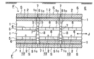
図示する実施の形態はたとえば既設覆工Fの軸方向(J方向)に複数の補強リング10,…を連続的に施工して任意延長区間を補強するものであり、周方向(C方向)の補強リング10を構成する弧状ブロック1,1間の空間Gを台形状としてここに台形状の第1の楔(間隔保持材5)を配設するのと同じように、軸方向においても、隣接する補強リング10,10間における対応する弧状ブロック1,1同士の端面1c、1cをテーパー状に形成し、補強リング10,10間に台形状の空間を形成する。そして、この台形状空間と同形状の第2の楔7,7を配し、第2の楔7,7間に間詰め部8を施工して補強リング10,10同士を軸方向に強固に繋ぐものである。
In the illustrated embodiment, for example, a plurality of reinforcing
なお、図1,2で示す既設覆工Fの内面の周方向に間隔Gを置いて配設される複数の弧状ブロック1,…と、それぞれの間隔G内に配される図3で示すジャッキ3であって、複数のジャッキ3,…を張り出させてそれぞれの弧状ブロック1,1間の間隔Gを広げながら周方向の軸力Nをそれぞれの弧状ブロックに付与するジャッキ3と、広げられた間隔G内に配されて該間隔Gを保持する図5で示す間隔保持材5と、からなり、ジャッキ3が間隔Gから取り外された際のジャッキ反力を間隔保持材5が受け替え、少なくとも周方向に配設された複数の弧状ブロック1,…と複数の間隔保持材5,…から既設覆工の補強装置が構成される。
A plurality of arc-shaped
この補強装置は、その構成部材である弧状ブロック1の既設覆工側の外面1bにゴム素材の緩衝層2を具備しているのが好ましい。
This reinforcing device preferably includes a
また、補強装置の他の実施の形態として、図9で示すように、補強リング10は既設覆工Fの軸方向(J方向)に間隔を置いて配設されるものであり、隣接する補強リング10,10の対向する2つの弧状ブロック1,1の該軸方向の端面1c、1cもテーパー面となっており、これによって軸方向の間隔は平面視台形状を呈しており、該軸方向の間隔内に平面視台形状の第2の楔7が配されている実施の形態であってもよい。
As another embodiment of the reinforcing device, as shown in FIG. 9, the reinforcing
以上、本発明の実施の形態を図面を用いて詳述してきたが、具体的な構成はこの実施形態に限定されるものではなく、本発明の要旨を逸脱しない範囲における設計変更等があっても、それらは本発明に含まれるものである。 The embodiment of the present invention has been described in detail with reference to the drawings. However, the specific configuration is not limited to this embodiment, and there are design changes and the like without departing from the gist of the present invention. They are also included in the present invention.
1…弧状ブロック、1a…周方向の端面、1b…既設覆工側の外面、2…緩衝層、3…ジャッキ、4…角度調整用挿入具、5…間隔保持材(第1の楔)、6…間詰め部、7…間隔保持材(第2の楔)、8…間詰め部、10…補強リング、G…間隔、S…セグメント、F…既設覆工、E…地盤(地山)、C…周方向、J…既設覆工の軸方向
DESCRIPTION OF
Claims (12)
複数のジャッキを張り出させてそれぞれの弧状ブロック間の間隔を広げながら周方向の軸力をそれぞれの弧状ブロックに付与する第2のステップ、
広げられた前記間隔を保持する間隔保持材を複数の該間隔内に配し、ジャッキを該間隔から取り外してジャッキ反力を間隔保持材に受け替えて、少なくとも周方向に配設された複数の弧状ブロックと複数の間隔保持材からなる補強リングを形成する第3のステップ、からなる既設覆工の補強方法。 A first step of arranging a plurality of arc-shaped blocks at intervals in the circumferential direction of the inner surface of the existing lining having a circular or substantially circular cross section in the underground tunnel, and arranging a jack in the interval;
A second step of applying a circumferential axial force to each arc-shaped block while extending a plurality of jacks to widen the interval between the arc-shaped blocks;
A plurality of spacing members that are arranged in the circumferential direction are arranged at least in the circumferential direction by disposing a spacing member that retains the spread spacing in the plurality of spacings, removing the jack from the spacing and replacing the jack reaction force with the spacing member. A method for reinforcing an existing lining, comprising a third step of forming a reinforcing ring comprising an arc-shaped block and a plurality of spacing members.
前記間隔保持材は前記間隔と同じ断面視台形状の第1の楔となっている請求項1に記載の既設覆工の補強方法。 Among the arc-shaped blocks, an end surface facing an adjacent arc-shaped block has a tapered surface inclined from the existing tunnel side to the inside of the tunnel, and the interval has a trapezoidal shape in a sectional view extending to the inside of the tunnel by two tapered surfaces on both sides thereof. Presents
The method of reinforcing an existing lining according to claim 1, wherein the spacing member is a first wedge having a trapezoidal cross-sectional shape that is the same as the spacing.
前記第3のステップでは、前記間隔保持材を前記端面における該ジャッキの両側に配す、請求項1〜3のいずれかに記載の既設覆工の補強方法。 In the first step, the jack is arranged at a substantially central position of the end face of the arc-shaped block,
The reinforcing method of the existing lining according to any one of claims 1 to 3, wherein, in the third step, the spacing member is disposed on both sides of the jack on the end surface.
それぞれの前記間隔内に配されるジャッキであって、複数のジャッキを張り出させてそれぞれの弧状ブロック間の間隔を広げながら周方向の軸力をそれぞれの弧状ブロックに付与するジャッキと、
広げられた前記間隔内に配されて該間隔を保持する間隔保持材と、からなり、
ジャッキが前記間隔から取り外された際のジャッキ反力を前記間隔保持材が受け替え、少なくとも周方向に配設された複数の弧状ブロックと複数の間隔保持材からなる補強リングを形成する、既設覆工の補強装置。 A plurality of arc-shaped blocks arranged at intervals in the circumferential direction of the inner surface of the existing lining having a circular or substantially circular cross section in the underground tunnel;
Jacks that are arranged in each of the intervals, and a jack that applies a circumferential axial force to each arc-shaped block while extending a plurality of jacks to widen the interval between the arc-shaped blocks, and
An interval holding material that is arranged in the spread interval and holds the interval;
The existing cover that replaces the reaction force of the jack when the jack is removed from the gap, and forms a reinforcing ring composed of a plurality of arc-shaped blocks arranged at least in the circumferential direction and a plurality of gap retainers. Work reinforcement device.
前記間隔保持材は前記間隔と同じ断面視台形状の第1の楔となっている請求項9に記載の既設覆工の補強装置。 Among the arc-shaped blocks, an end surface facing an adjacent arc-shaped block has a tapered surface inclined from the existing tunnel side to the inside of the tunnel, and the interval has a trapezoidal shape in a sectional view extending to the inside of the tunnel by two tapered surfaces on both sides thereof. Presents
The reinforcing device for an existing lining according to claim 9, wherein the spacing member is a first wedge having a trapezoidal cross-sectional shape that is the same as the spacing.
Priority Applications (1)
| Application Number | Priority Date | Filing Date | Title |
|---|---|---|---|
| JP2011059541A JP5689342B2 (en) | 2011-03-17 | 2011-03-17 | Reinforcing method and equipment for existing lining |
Applications Claiming Priority (1)
| Application Number | Priority Date | Filing Date | Title |
|---|---|---|---|
| JP2011059541A JP5689342B2 (en) | 2011-03-17 | 2011-03-17 | Reinforcing method and equipment for existing lining |
Publications (2)
| Publication Number | Publication Date |
|---|---|
| JP2012193577A true JP2012193577A (en) | 2012-10-11 |
| JP5689342B2 JP5689342B2 (en) | 2015-03-25 |
Family
ID=47085713
Family Applications (1)
| Application Number | Title | Priority Date | Filing Date |
|---|---|---|---|
| JP2011059541A Expired - Fee Related JP5689342B2 (en) | 2011-03-17 | 2011-03-17 | Reinforcing method and equipment for existing lining |
Country Status (1)
| Country | Link |
|---|---|
| JP (1) | JP5689342B2 (en) |
Cited By (7)
| Publication number | Priority date | Publication date | Assignee | Title |
|---|---|---|---|---|
| JP2012246650A (en) * | 2011-05-26 | 2012-12-13 | Taisei Corp | Tunnel lining and reinforcement structure and tunnel lining and reinforcement method |
| CN103257080A (en) * | 2013-05-23 | 2013-08-21 | 西南交通大学 | Prototype test device for shield tunnel dual-layer lining structure and secondary lining pouring device |
| JP2015067946A (en) * | 2013-09-26 | 2015-04-13 | 清水建設株式会社 | Tunnel reinforcement method, steel segment piece lifting device, and steel segment piece |
| KR101857722B1 (en) * | 2017-10-25 | 2018-06-26 | 휴먼이엔씨 주식회사 | Reinforced apparatus for culvert |
| CN109001039A (en) * | 2018-07-03 | 2018-12-14 | 上海隧道工程有限公司 | Section of jurisdiction load and side cutting test loading equipemtn and its side cutting method |
| JP2019078073A (en) * | 2017-10-25 | 2019-05-23 | 積水化学工業株式会社 | Timbering device and timbering construction method |
| JP2019167772A (en) * | 2018-03-26 | 2019-10-03 | 公益財団法人鉄道総合技術研究所 | Back natural ground stiffness evaluation device and stiffness evaluation method thereof, and tunnel lining deformation repair device and deformation repair method thereof |
Citations (7)
| Publication number | Priority date | Publication date | Assignee | Title |
|---|---|---|---|---|
| JPS4973827A (en) * | 1972-11-22 | 1974-07-17 | ||
| JPS49150834U (en) * | 1973-04-25 | 1974-12-27 | ||
| JPS5115538A (en) * | 1974-07-30 | 1976-02-07 | Komatsu Mfg Co Ltd | Shiirudokoho niokeru kakukeisegumentono sochakuhoho |
| JPH06248882A (en) * | 1993-03-01 | 1994-09-06 | Mitsui Constr Co Ltd | Tunnel structure |
| JPH1037685A (en) * | 1996-07-29 | 1998-02-10 | Kajima Corp | Tunnel support material support method and support device |
| JP2001323792A (en) * | 2000-05-12 | 2001-11-22 | Yoshiji Matsumoto | Reinforcement method of existing tunnel |
| JP2007100415A (en) * | 2005-10-05 | 2007-04-19 | Kawada Industries Inc | Floor slab demolition method and floor slab demolition apparatus |
-
2011
- 2011-03-17 JP JP2011059541A patent/JP5689342B2/en not_active Expired - Fee Related
Patent Citations (7)
| Publication number | Priority date | Publication date | Assignee | Title |
|---|---|---|---|---|
| JPS4973827A (en) * | 1972-11-22 | 1974-07-17 | ||
| JPS49150834U (en) * | 1973-04-25 | 1974-12-27 | ||
| JPS5115538A (en) * | 1974-07-30 | 1976-02-07 | Komatsu Mfg Co Ltd | Shiirudokoho niokeru kakukeisegumentono sochakuhoho |
| JPH06248882A (en) * | 1993-03-01 | 1994-09-06 | Mitsui Constr Co Ltd | Tunnel structure |
| JPH1037685A (en) * | 1996-07-29 | 1998-02-10 | Kajima Corp | Tunnel support material support method and support device |
| JP2001323792A (en) * | 2000-05-12 | 2001-11-22 | Yoshiji Matsumoto | Reinforcement method of existing tunnel |
| JP2007100415A (en) * | 2005-10-05 | 2007-04-19 | Kawada Industries Inc | Floor slab demolition method and floor slab demolition apparatus |
Cited By (10)
| Publication number | Priority date | Publication date | Assignee | Title |
|---|---|---|---|---|
| JP2012246650A (en) * | 2011-05-26 | 2012-12-13 | Taisei Corp | Tunnel lining and reinforcement structure and tunnel lining and reinforcement method |
| CN103257080A (en) * | 2013-05-23 | 2013-08-21 | 西南交通大学 | Prototype test device for shield tunnel dual-layer lining structure and secondary lining pouring device |
| CN103257080B (en) * | 2013-05-23 | 2015-10-14 | 西南交通大学 | Secondary lining builds device |
| JP2015067946A (en) * | 2013-09-26 | 2015-04-13 | 清水建設株式会社 | Tunnel reinforcement method, steel segment piece lifting device, and steel segment piece |
| KR101857722B1 (en) * | 2017-10-25 | 2018-06-26 | 휴먼이엔씨 주식회사 | Reinforced apparatus for culvert |
| JP2019078073A (en) * | 2017-10-25 | 2019-05-23 | 積水化学工業株式会社 | Timbering device and timbering construction method |
| JP7032100B2 (en) | 2017-10-25 | 2022-03-08 | 積水化学工業株式会社 | Support equipment and support construction method |
| JP2019167772A (en) * | 2018-03-26 | 2019-10-03 | 公益財団法人鉄道総合技術研究所 | Back natural ground stiffness evaluation device and stiffness evaluation method thereof, and tunnel lining deformation repair device and deformation repair method thereof |
| CN109001039A (en) * | 2018-07-03 | 2018-12-14 | 上海隧道工程有限公司 | Section of jurisdiction load and side cutting test loading equipemtn and its side cutting method |
| CN109001039B (en) * | 2018-07-03 | 2020-10-27 | 上海隧道工程有限公司 | Segment loading and lateral cutting test loading equipment and lateral cutting method thereof |
Also Published As
| Publication number | Publication date |
|---|---|
| JP5689342B2 (en) | 2015-03-25 |
Similar Documents
| Publication | Publication Date | Title |
|---|---|---|
| JP5689342B2 (en) | Reinforcing method and equipment for existing lining | |
| US10746022B2 (en) | Helical segmental lining | |
| KR101066641B1 (en) | Prestressed Sunbeam Tunnel Construction Method and Appropriate Device | |
| JP6127193B1 (en) | Construction method of large section underground structure | |
| JP6493736B2 (en) | Tunnel segment diameter reducing device, tunnel lining structure, and freeze expansion countermeasure method | |
| KR101139505B1 (en) | Timbering structure for tunnel and construction method thereof | |
| CN103614974B (en) | Prestress sectional steel reinforcing system of reinforced concrete arch shell bridge body | |
| JP2018012945A (en) | Construction method of large section underground structure | |
| JP5491212B2 (en) | Concrete slab construction method and concrete slab | |
| KR20160000792A (en) | Natm tunnel structure and construction method thereof | |
| CN116517022B (en) | High-toughness comprehensive pipe rack in strong earthquake area and manufacturing method | |
| JP4844929B2 (en) | Tunnel construction method | |
| JP6257814B1 (en) | Construction method of large section underground structure | |
| CN120251888A (en) | A prestressed lining structure and construction method for underground gas storage | |
| CN114753862B (en) | A reinforcement device and reinforcement method for damaged segments of shield tunnel | |
| JP2017008522A (en) | Composite steel shell member and method of manufacturing the same | |
| JP3350679B2 (en) | Tunnel lining segment and construction method | |
| JP7456954B2 (en) | Reinforcement structure and reinforcement method | |
| CN111396080B (en) | A construction method for arch-replacing in the initial support intrusion limit section of a tunnel | |
| JP2013160029A (en) | Tunnel structure and method for constructing the same | |
| CN223256834U (en) | Reinforcing structure for lining of arch wall of existing tunnel | |
| KR20090034716A (en) | Underground Tunnel Construction Method Using Hybrid Cell Element System | |
| JP6874375B2 (en) | How to build a tunnel skeleton | |
| CN110645012A (en) | A kind of tunnel segment with deformation and energy release and using method thereof | |
| JP2007321450A (en) | Mounting structure of PC plate for lining and the PC plate |
Legal Events
| Date | Code | Title | Description |
|---|---|---|---|
| A621 | Written request for application examination |
Free format text: JAPANESE INTERMEDIATE CODE: A621 Effective date: 20131016 |
|
| A977 | Report on retrieval |
Free format text: JAPANESE INTERMEDIATE CODE: A971007 Effective date: 20140529 |
|
| A131 | Notification of reasons for refusal |
Free format text: JAPANESE INTERMEDIATE CODE: A131 Effective date: 20140924 |
|
| A521 | Request for written amendment filed |
Free format text: JAPANESE INTERMEDIATE CODE: A523 Effective date: 20141112 |
|
| A131 | Notification of reasons for refusal |
Free format text: JAPANESE INTERMEDIATE CODE: A131 Effective date: 20141202 |
|
| A521 | Request for written amendment filed |
Free format text: JAPANESE INTERMEDIATE CODE: A523 Effective date: 20141217 |
|
| TRDD | Decision of grant or rejection written | ||
| A01 | Written decision to grant a patent or to grant a registration (utility model) |
Free format text: JAPANESE INTERMEDIATE CODE: A01 Effective date: 20150113 |
|
| A61 | First payment of annual fees (during grant procedure) |
Free format text: JAPANESE INTERMEDIATE CODE: A61 Effective date: 20150128 |
|
| R150 | Certificate of patent or registration of utility model |
Ref document number: 5689342 Country of ref document: JP Free format text: JAPANESE INTERMEDIATE CODE: R150 |
|
| R250 | Receipt of annual fees |
Free format text: JAPANESE INTERMEDIATE CODE: R250 |
|
| LAPS | Cancellation because of no payment of annual fees |