JP2012194656A - Operation support device - Google Patents
Operation support device Download PDFInfo
- Publication number
- JP2012194656A JP2012194656A JP2011056676A JP2011056676A JP2012194656A JP 2012194656 A JP2012194656 A JP 2012194656A JP 2011056676 A JP2011056676 A JP 2011056676A JP 2011056676 A JP2011056676 A JP 2011056676A JP 2012194656 A JP2012194656 A JP 2012194656A
- Authority
- JP
- Japan
- Prior art keywords
- obstacle
- vehicle
- threshold
- transmission
- count value
- Prior art date
- Legal status (The legal status is an assumption and is not a legal conclusion. Google has not performed a legal analysis and makes no representation as to the accuracy of the status listed.)
- Granted
Links
Images


Classifications
-
- G—PHYSICS
- G01—MEASURING; TESTING
- G01S—RADIO DIRECTION-FINDING; RADIO NAVIGATION; DETERMINING DISTANCE OR VELOCITY BY USE OF RADIO WAVES; LOCATING OR PRESENCE-DETECTING BY USE OF THE REFLECTION OR RERADIATION OF RADIO WAVES; ANALOGOUS ARRANGEMENTS USING OTHER WAVES
- G01S15/00—Systems using the reflection or reradiation of acoustic waves, e.g. sonar systems
- G01S15/02—Systems using the reflection or reradiation of acoustic waves, e.g. sonar systems using reflection of acoustic waves
- G01S15/06—Systems determining the position data of a target
- G01S15/08—Systems for measuring distance only
- G01S15/10—Systems for measuring distance only using transmission of interrupted, pulse-modulated waves
-
- B—PERFORMING OPERATIONS; TRANSPORTING
- B60—VEHICLES IN GENERAL
- B60W—CONJOINT CONTROL OF VEHICLE SUB-UNITS OF DIFFERENT TYPE OR DIFFERENT FUNCTION; CONTROL SYSTEMS SPECIALLY ADAPTED FOR HYBRID VEHICLES; ROAD VEHICLE DRIVE CONTROL SYSTEMS FOR PURPOSES NOT RELATED TO THE CONTROL OF A PARTICULAR SUB-UNIT
- B60W30/00—Purposes of road vehicle drive control systems not related to the control of a particular sub-unit, e.g. of systems using conjoint control of vehicle sub-units
- B60W30/08—Active safety systems predicting or avoiding probable or impending collision or attempting to minimise its consequences
- B60W30/095—Predicting travel path or likelihood of collision
- B60W30/0956—Predicting travel path or likelihood of collision the prediction being responsive to traffic or environmental parameters
-
- G—PHYSICS
- G01—MEASURING; TESTING
- G01S—RADIO DIRECTION-FINDING; RADIO NAVIGATION; DETERMINING DISTANCE OR VELOCITY BY USE OF RADIO WAVES; LOCATING OR PRESENCE-DETECTING BY USE OF THE REFLECTION OR RERADIATION OF RADIO WAVES; ANALOGOUS ARRANGEMENTS USING OTHER WAVES
- G01S15/00—Systems using the reflection or reradiation of acoustic waves, e.g. sonar systems
- G01S15/02—Systems using the reflection or reradiation of acoustic waves, e.g. sonar systems using reflection of acoustic waves
- G01S15/50—Systems of measurement, based on relative movement of the target
- G01S15/58—Velocity or trajectory determination systems; Sense-of-movement determination systems
- G01S15/582—Velocity or trajectory determination systems; Sense-of-movement determination systems using transmission of interrupted pulse-modulated waves and based upon the Doppler effect resulting from movement of targets
-
- G—PHYSICS
- G01—MEASURING; TESTING
- G01S—RADIO DIRECTION-FINDING; RADIO NAVIGATION; DETERMINING DISTANCE OR VELOCITY BY USE OF RADIO WAVES; LOCATING OR PRESENCE-DETECTING BY USE OF THE REFLECTION OR RERADIATION OF RADIO WAVES; ANALOGOUS ARRANGEMENTS USING OTHER WAVES
- G01S15/00—Systems using the reflection or reradiation of acoustic waves, e.g. sonar systems
- G01S15/87—Combinations of sonar systems
-
- G—PHYSICS
- G01—MEASURING; TESTING
- G01S—RADIO DIRECTION-FINDING; RADIO NAVIGATION; DETERMINING DISTANCE OR VELOCITY BY USE OF RADIO WAVES; LOCATING OR PRESENCE-DETECTING BY USE OF THE REFLECTION OR RERADIATION OF RADIO WAVES; ANALOGOUS ARRANGEMENTS USING OTHER WAVES
- G01S15/00—Systems using the reflection or reradiation of acoustic waves, e.g. sonar systems
- G01S15/88—Sonar systems specially adapted for specific applications
- G01S15/93—Sonar systems specially adapted for specific applications for anti-collision purposes
- G01S15/931—Sonar systems specially adapted for specific applications for anti-collision purposes of land vehicles
-
- B—PERFORMING OPERATIONS; TRANSPORTING
- B60—VEHICLES IN GENERAL
- B60W—CONJOINT CONTROL OF VEHICLE SUB-UNITS OF DIFFERENT TYPE OR DIFFERENT FUNCTION; CONTROL SYSTEMS SPECIALLY ADAPTED FOR HYBRID VEHICLES; ROAD VEHICLE DRIVE CONTROL SYSTEMS FOR PURPOSES NOT RELATED TO THE CONTROL OF A PARTICULAR SUB-UNIT
- B60W2420/00—Indexing codes relating to the type of sensors based on the principle of their operation
- B60W2420/60—Doppler effect
-
- B—PERFORMING OPERATIONS; TRANSPORTING
- B60—VEHICLES IN GENERAL
- B60W—CONJOINT CONTROL OF VEHICLE SUB-UNITS OF DIFFERENT TYPE OR DIFFERENT FUNCTION; CONTROL SYSTEMS SPECIALLY ADAPTED FOR HYBRID VEHICLES; ROAD VEHICLE DRIVE CONTROL SYSTEMS FOR PURPOSES NOT RELATED TO THE CONTROL OF A PARTICULAR SUB-UNIT
- B60W2554/00—Input parameters relating to objects
- B60W2554/40—Dynamic objects, e.g. animals, windblown objects
- B60W2554/404—Characteristics
- B60W2554/4041—Position
-
- G—PHYSICS
- G01—MEASURING; TESTING
- G01S—RADIO DIRECTION-FINDING; RADIO NAVIGATION; DETERMINING DISTANCE OR VELOCITY BY USE OF RADIO WAVES; LOCATING OR PRESENCE-DETECTING BY USE OF THE REFLECTION OR RERADIATION OF RADIO WAVES; ANALOGOUS ARRANGEMENTS USING OTHER WAVES
- G01S15/00—Systems using the reflection or reradiation of acoustic waves, e.g. sonar systems
- G01S15/88—Sonar systems specially adapted for specific applications
- G01S15/93—Sonar systems specially adapted for specific applications for anti-collision purposes
- G01S15/931—Sonar systems specially adapted for specific applications for anti-collision purposes of land vehicles
- G01S2015/932—Sonar systems specially adapted for specific applications for anti-collision purposes of land vehicles for parking operations
- G01S2015/933—Sonar systems specially adapted for specific applications for anti-collision purposes of land vehicles for parking operations for measuring the dimensions of the parking space when driving past
-
- G—PHYSICS
- G01—MEASURING; TESTING
- G01S—RADIO DIRECTION-FINDING; RADIO NAVIGATION; DETERMINING DISTANCE OR VELOCITY BY USE OF RADIO WAVES; LOCATING OR PRESENCE-DETECTING BY USE OF THE REFLECTION OR RERADIATION OF RADIO WAVES; ANALOGOUS ARRANGEMENTS USING OTHER WAVES
- G01S15/00—Systems using the reflection or reradiation of acoustic waves, e.g. sonar systems
- G01S15/88—Sonar systems specially adapted for specific applications
- G01S15/93—Sonar systems specially adapted for specific applications for anti-collision purposes
- G01S15/931—Sonar systems specially adapted for specific applications for anti-collision purposes of land vehicles
- G01S2015/937—Sonar systems specially adapted for specific applications for anti-collision purposes of land vehicles sensor installation details
- G01S2015/938—Sonar systems specially adapted for specific applications for anti-collision purposes of land vehicles sensor installation details in the bumper area
Landscapes
- Engineering & Computer Science (AREA)
- Radar, Positioning & Navigation (AREA)
- Remote Sensing (AREA)
- Physics & Mathematics (AREA)
- Computer Networks & Wireless Communication (AREA)
- General Physics & Mathematics (AREA)
- Acoustics & Sound (AREA)
- Automation & Control Theory (AREA)
- Transportation (AREA)
- Mechanical Engineering (AREA)
- Traffic Control Systems (AREA)
- Measurement Of Velocity Or Position Using Acoustic Or Ultrasonic Waves (AREA)
Abstract
【課題】自車両周辺の障害物の検出を、ドップラー効果を利用しながらもより容易に行うことを可能にする汎用性の高い運転支援装置を提供する。
【解決手段】送受信マイク13から送波した送信波の周波数と同期した周波数の基準信号の位相と送受信マイク13で受信した当該送信波の反射波の位相とを比較して、当該基準信号に対する位相の進みと遅れとに対応した2値パルスを生成し、その2値パルスの所定時間におけるパルス数をカウントする相対速度範囲判定回路17と、受信した反射波をもとに自車両の周囲に障害物が存在すると判定したこと、および相対速度範囲判定回路17でカウントしたカウント値が第1設定値以下であることをもとに、自車両の並走車両の存在を検出する制御装置11を備える。
【選択図】図2An object of the present invention is to provide a highly versatile driving support device that can easily detect an obstacle around a host vehicle while using the Doppler effect.
A phase of a reference signal having a frequency synchronized with a frequency of a transmission wave transmitted from a transmission / reception microphone is compared with a phase of a reflection wave of the transmission wave received by the transmission / reception microphone, and a phase with respect to the reference signal is compared. A relative speed range determination circuit 17 that generates a binary pulse corresponding to the advance and delay of the vehicle and counts the number of pulses of the binary pulse at a predetermined time, and an obstacle around the vehicle based on the received reflected wave A control device 11 is provided that detects the presence of a parallel running vehicle of the host vehicle based on the determination that an object is present and that the count value counted by the relative speed range determination circuit 17 is equal to or less than the first set value. .
[Selection] Figure 2
Description
本発明は、運転支援装置に関するものである。 The present invention relates to a driving support device.
従来から、自車両周辺の障害物をセンサによって検出することでドライバの運転を支援する技術が知られている。例えば特許文献1には、超音波センサによって、死角の範囲内にある並走車両の存在および並走車両の相対速度を検出する技術が開示されている。
2. Description of the Related Art Conventionally, a technique for assisting a driver's driving by detecting an obstacle around the host vehicle with a sensor is known. For example,
詳しくは、特許文献1に開示の技術では、超音波の送受信波の周波数分析を行って送信波の周波数と受信波の周波数との差を検出し、この送受信波の周波数差に基づいて並走車両との相対速度を検出する。即ち、動いている物体にある角度で超音波をあてると、戻ってくる超音波の周波数がシフトする、いわゆるドップラー効果を利用して、周波数のシフト量に応じて相対速度を検出する。
Specifically, in the technique disclosed in
また、特許文献1に開示の技術では、超音波センサの受信器の周波数帯域を送信波の周波数に対して±α(kHz)の範囲の帯域に制限し、シフト量がαを越えない受信波を検出した場合に、相対速度が低い物体、つまり、並走車両を認識したものとしている。
In the technique disclosed in
しかしながら、特許文献1に開示の技術では、並走車両を検出するために、超音波センサの受信器の周波数帯域を、送信波の周波数に対して±αの範囲に制限してしまっている。よって、制限された帯域以外の周波数の反射波を受信せず、並走車両以外については存在を全く検出できないという問題があった。つまり、汎用性が低いという問題点があった。
However, in the technique disclosed in
また、特許文献1に開示の技術では、送信波の周波数と受信波の周波数との差を検出可能とするため、周波数分析を行っている。しかしながら、例えば周波数分析として一般的なFFT(Fast Fourier Transform)のように、周波数分析においては周波数の検出に複雑な分析を必要とし、手間がかかるという問題点があった。
In the technique disclosed in
本発明は、上記従来の問題点に鑑みなされたものであって、その目的は、自車両周辺の障害物の検出を、ドップラー効果を利用しながらもより容易に行うことを可能にする汎用性の高い運転支援装置を提供することにある。 The present invention has been made in view of the above-described conventional problems, and the purpose thereof is versatility that makes it possible to more easily detect obstacles around the host vehicle while using the Doppler effect. It is to provide a driving assistance device with high cost.
請求項1の運転支援装置においては、送信波の周波数と同期した周波数の基準信号の位相と受信手段で受信したその送信波の反射波の位相とを比較し、基準信号に対する位相の進みと遅れとに対応した2値パルスを生成する2値パルス生成手段と、2値パルス生成手段で生成した2値パルスの所定時間におけるパルス数をカウントするカウント手段と、受信手段で受信した反射波をもとに車両の周囲の障害物の存在の有無を判定する障害物有無判定手段で障害物が存在すると判定したこと、およびカウント手段でカウントしたカウント値をもとに、車両の周辺の障害物の存在を検出する検出手段とを備えることになる。なお、パルス数とは、例えばパルスの立ち上がりの数、パルスの立下りの数、パルスの立ち上がりから立下りまでの数等である。
In the driving support device according to
障害物で反射された反射波の周波数は、ドップラー効果によってその障害物の相対速度が大きいほど基準信号の周波数からずれるので、障害物の相対速度が大きいほど反射波の位相は、基準信号の位相に対して一定の時間内における進みや遅れの頻度が増加することになる。つまり、障害物の相対速度が大きいほどカウント手段でカウントされるカウント値は大きい値になり、障害物の相対速度が小さいほどカウント手段でカウントされるカウント値は小さい値になる。よって、カウント値の大小をもとに、相対速度が小さい並走車両や追従車両の存在を精度良く検出したり、相対速度が大きい接触危険性物体(自車両と接触する危険性のある物体)の存在を精度良く検出したりすることが可能になる。 The frequency of the reflected wave reflected by the obstacle shifts from the reference signal frequency as the obstacle's relative velocity increases due to the Doppler effect, so the phase of the reflected wave becomes the phase of the reference signal as the obstacle's relative velocity increases. On the other hand, the frequency of advance and delay within a certain time increases. That is, the count value counted by the counting means becomes larger as the relative speed of the obstacle is larger, and the count value counted by the counting means becomes smaller as the relative speed of the obstacle is smaller. Therefore, based on the count value, it is possible to accurately detect the presence of a parallel running vehicle with low relative speed or a following vehicle, or a contact dangerous object with a high relative speed (an object with a risk of contact with the host vehicle). Or the like can be detected with high accuracy.
障害物の相対速度の指標となる上記カウント値は、基準信号の位相と反射波の位相とを比較し、基準信号に対する位相の進みと遅れとに対応した2値パルスを生成して、所定時間におけるパルス数をカウントすれば得られる。位相の比較は例えば位相比較器を用いるなどして容易に行うことができるため、周波数分析を行って送信波の周波数と反射波の周波数との差を検出し、この差に基づいて障害物の相対速度を検出する構成に比べ、手間を減らすことができる。また、請求項1の構成によれば、以上のようにカウント値の大小をもとに、並走車両以外の障害物の存在も検出可能となるので汎用性を高くすることも可能になる。
The count value, which is an index of the relative speed of the obstacle, compares the phase of the reference signal with the phase of the reflected wave, generates a binary pulse corresponding to the phase advance and delay with respect to the reference signal, and generates a predetermined time. It can be obtained by counting the number of pulses at. The phase comparison can be easily performed by using, for example, a phase comparator. Therefore, the frequency analysis is performed to detect the difference between the frequency of the transmitted wave and the frequency of the reflected wave, and based on this difference, the obstacle is detected. Compared to the configuration for detecting the relative speed, labor can be reduced. Moreover, according to the structure of
その結果、自車両周辺の障害物の検出を、ドップラー効果を利用しながらもより容易に行うことを可能にする汎用性の高い運転支援装置を提供することが可能になる。 As a result, it is possible to provide a highly versatile driving support device that can more easily detect obstacles around the host vehicle while using the Doppler effect.
障害物との相対速度が同じ場合であっても、自車両の速度が小さくなるほど基準信号と反射波との位相差は小さくなり、カウント手段で値をカウントする時間が一定の場合には、カウント値は小さくなる。よって、カウント手段で値をカウントする時間が一定の場合には、自車両の速度が小さくなるほど検出手段での誤検出の可能性が高くなる。これに対して、請求項2の構成によれば、カウント手段は、車両の速度が小さくなるほど第1の所定時間を長く設定するので、車両の速度が小さくなるほどカウントされるパルス数を増やすことが可能になり、上記誤検出を防ぐことが可能になる。 Even if the relative speed to the obstacle is the same, the phase difference between the reference signal and the reflected wave becomes smaller as the speed of the host vehicle becomes smaller. The value becomes smaller. Therefore, when the time for counting values by the counting means is constant, the possibility of erroneous detection by the detecting means increases as the speed of the host vehicle decreases. On the other hand, according to the configuration of the second aspect, the counting means sets the first predetermined time longer as the vehicle speed decreases, so that the number of pulses counted can be increased as the vehicle speed decreases. This makes it possible to prevent the erroneous detection.
また、障害物との相対速度が同じ場合であっても、自車両の速度が小さくなるほど基準信号と反射波との位相差は小さくなり、送信手段での送信波の送信継続時間が一定の場合であって、上述の所定時間が十分でない場合には、カウント値は小さくなる。よって、送信手段での送信波の送信継続時間が一定の場合には、自車両の速度が小さくなるほど検出手段での誤検出の可能性が高くなる。これに対して、請求項3の構成によれば、車両の速度が小さくなるほど送信波の送信継続時間を長く設定するので、車両の速度が小さくなるほどカウントされるパルス数を増やすことが可能になり、上記誤検出を防ぐことが可能になる。 Even if the relative speed with the obstacle is the same, the phase difference between the reference signal and the reflected wave becomes smaller as the speed of the host vehicle becomes smaller, and the transmission duration of the transmission wave at the transmission means is constant. If the predetermined time is not sufficient, the count value becomes small. Therefore, when the transmission duration of the transmission wave at the transmission unit is constant, the possibility of erroneous detection by the detection unit increases as the speed of the host vehicle decreases. On the other hand, according to the configuration of the third aspect, since the transmission duration time of the transmission wave is set longer as the vehicle speed decreases, the number of pulses counted can be increased as the vehicle speed decreases. Thus, it is possible to prevent the erroneous detection.
請求項4のように、カウント手段でカウントしたカウント値を第1の閾値と比較し、カウント値が第1の閾値以下であるか否かを判定する第1閾値判定手段をさらに備え、検出手段は、障害物有無判定手段で障害物が存在すると判定したこと、および第1閾値判定手段でカウント値が第1の閾値以下であると判定したことをもとに、車両の並走車両および追従車両のいずれかの存在を検出する態様としてもよい。前述したように、障害物の相対速度が小さいほどカウント手段でカウントされるカウント値は小さい値になるので、以上の構成によれば、相対速度が小さい並走車両や追従車両の存在を精度良く検出することができる。 According to a fourth aspect of the present invention, the apparatus further comprises first threshold determination means for comparing the count value counted by the counting means with the first threshold and determining whether the count value is equal to or less than the first threshold, Is based on the fact that the obstacle presence / absence determining means determines that an obstacle is present and the first threshold value determining means determines that the count value is equal to or less than the first threshold value. It is good also as an aspect which detects the presence of either of vehicles. As described above, the smaller the relative speed of the obstacle, the smaller the count value counted by the counting means. Therefore, according to the above configuration, it is possible to accurately detect the presence of a parallel running vehicle or a following vehicle having a low relative speed. Can be detected.
請求項5のように、カウント手段でカウントしたカウント値を第2の閾値と比較し、カウント値が第2の閾値以上であるか否かを判定する第2閾値判定手段をさらに備え、検出手段は、障害物有無判定手段で障害物が存在すると判定したこと、および第2閾値判定手段でカウント値が第2の閾値以上であると判定したことをもとに、接触危険性物体の存在を検出する態様としてもよい。前述したように、障害物の相対速度が大きいほどカウント手段でカウントされるカウント値は大きい値になるので、以上の構成によれば、相対速度が大きい接触危険性物体の存在を精度良く検出することができる。
6. The detection device according to
請求項6のように、カウント手段でカウントしたカウント値を第1の閾値と比較し、カウント値が第1の閾値以下であるか否かを判定する第1閾値判定手段と、カウント手段でカウントしたカウント値を第2の閾値と比較し、カウント値が第2の閾値以上であるか否かを判定する第2閾値判定手段とをさらに備え、検出手段は、障害物有無判定手段で障害物が存在すると判定したこと、および第1閾値判定手段でカウント値が第1の閾値以下であると判定したことをもとに、車両の並走車両および追従車両のいずれかの存在を検出する一方、障害物有無判定手段で障害物が存在すると判定したこと、および第2閾値判定手段でカウント値が第2の閾値以上であると判定したことをもとに、接触危険性物体の存在を検出する態様としてもよい。前述したように、障害物の相対速度が小さいほどカウント手段でカウントされるカウント値は小さい値になり、障害物の相対速度が大きいほどカウント手段でカウントされるカウント値は大きい値になる。よって、以上の構成によれば、相対速度が小さい並走車両や追従車両の存在や相対速度が大きい接触危険性物体の存在を精度良く検出することができる。 The count value counted by the counting means is compared with a first threshold value, and the first threshold value judging means for judging whether or not the count value is equal to or less than the first threshold value, and the counting means counts. And a second threshold value judging means for comparing the counted value with the second threshold value and judging whether or not the count value is equal to or larger than the second threshold value. The detecting means is an obstacle presence / absence judging means. And detecting the presence of either a parallel running vehicle or a following vehicle based on the determination that the vehicle is present and the count value is determined to be less than or equal to the first threshold value by the first threshold value determination means. The presence of a contact risk object is detected based on the fact that the obstacle presence / absence judging means judges that an obstacle is present and the second threshold judging means judges that the count value is equal to or larger than the second threshold. It is good also as an aspect to do. As described above, the smaller the relative speed of the obstacle, the smaller the count value counted by the counting means, and the larger the relative speed of the obstacle, the larger the count value counted by the counting means. Therefore, according to the above configuration, it is possible to accurately detect the presence of a parallel running vehicle having a low relative speed, a following vehicle, or a contact risky object having a high relative speed.
請求項7の構成によれば、検出手段で接触危険性物体の存在を検出した場合に、車両と接触危険性物体との接触の回避の支援、および車両と接触危険性物体とが接触した場合に車両の乗員を保護するための装置の作動の少なくともいずれが接触対応手段で行われることになる。よって、接触危険性物体との接触の回避を行い易くなったり、接触危険性物体と接触した場合に乗員の衝撃を緩和したりすることが可能になる。 According to the configuration of claim 7, when the presence of the contact risk object is detected by the detection means, the avoidance of contact between the vehicle and the contact risk object, and the vehicle and the contact risk object are in contact with each other In addition, at least any of the operations of the device for protecting the vehicle occupant is performed by the contact handling means. Therefore, it becomes easy to avoid contact with the contact risk object, and it is possible to reduce the impact of the occupant when it comes into contact with the contact risk object.
請求項8の構成においては、送信波を送信した時間とその送信波の反射波を受信した時間との差に基づいて、障害物までの距離を算出する距離算出手段をさらに備え、検出手段は、障害物有無判定手段で障害物が存在すると判定したこと、および第1閾値判定手段でカウント値が第1の閾値以下であると判定したことに加え、距離算出手段で算出した障害物までの距離をもとにして、車両の並走車両および追従車両の存在を検出することになる。これによれば、障害物までの距離が一定値以内の場合に並走車両や追従車両とする一方、距離が一定値よりも離れている場合に並走車両や追従車両としないといったように、距離も考慮して並走車両や追従車両の存在を検出することが可能になるので、検出精度をより高めることが可能になる。
In the configuration of
請求項9の構成においては、送信波を送信した時間とその送信波の反射波を受信した時間との差に基づいて、障害物までの距離を算出する距離算出手段をさらに備え、検出手段は、障害物有無判定手段で障害物が存在すると判定したこと、および第2閾値判定手段でカウント値が第2の閾値以上であると判定したことに加え、距離算出手段で算出した障害物までの距離をもとにして、接触危険性物体の存在を検出することになる。これによれば、障害物までの距離が一定値以内の場合に接触危険性物体とする一方、距離が一定値よりも離れている場合に接触危険性物体としないといったように、距離も考慮して接触危険性物体の存在を検出することが可能になるので、検出精度をより高めることが可能になる。
The configuration of
請求項10の構成によれば、報知手段で検出手段での検出結果に応じた報知を行うので、
検出手段で検出した並走車両や追従車両や接触危険性物体の存在を車両の乗員が認識することが可能となる。
According to the configuration of the tenth aspect, since the notification according to the detection result of the detection unit is performed by the notification unit,
The vehicle occupant can recognize the presence of the parallel running vehicle, the following vehicle, or the contact risk object detected by the detection means.
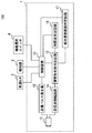
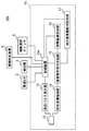
以下、本発明の実施形態について図面を用いて説明する。図1は、本発明が適用された運転支援システム100の概略的な構成を示すブロック図である。図1に示す運転支援システム100は、車両に搭載されるものであり、障害物検出装置1、車速センサ2、報知器3、および機能選択スイッチ4を含んでいる。なお、運転支援システム100を搭載している車両を以降では自車両と呼ぶ。
Hereinafter, embodiments of the present invention will be described with reference to the drawings. FIG. 1 is a block diagram showing a schematic configuration of a driving
車速センサ2は、自車両の速度(つまり、車速)を検出するセンサである。報知器3は、自車両のドライバに報知を行う。例えば、報知器3はスピーカを用いて構成され、障害物検出装置1の指示に従って音声出力するものとする。なお、報知器3は、ディスプレイを用いて構成され、障害物検出装置1の指示に従ってテキスト表示や画像表示を行う構成としてもよいし、障害物検出装置1の指示に従ってLED等のインジケータ表示を行う構成としてもよい。また、これらを組み合わせた構成としてもよい。機能選択スイッチ4は、障害物検出装置1で自車両周辺の障害物の検出を行わせるか否かを選択するスイッチであり、例えば自車両のドライバが操作可能な位置に設けられている。
The
障害物検出装置1は、自車両周辺の障害物の検出を行うものであって、図1に示すように、制御装置11、送信パルス発生器12、送受信マイク13、受信波増幅回路14、障害物有無判定回路15、時間差測定回路16、および相対速度範囲判定回路17を備えている。制御装置11は、通常のコンピュータとして構成されており、内部には例えば周知のCPU、ROM、EEPROM、RAM、I/O及びこれらの構成を接続するバスライン(いずれも図示せず)等が備えられている。
The
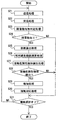
ここで、図2を用いて、障害物検出装置1の動作フローについての説明を行う。図2は、障害物検出装置1の動作フローを示すフローチャートである。本フローは、機能選択スイッチ4で自車両周辺の障害物の検出を行わせる選択が行われた場合にフローを開始する。機能選択スイッチ4で自車両周辺の障害物の検出を行わせる選択が行われている状態を機能選択オンとし、選択が行われなくなった状態を機能選択オフとする。
Here, the operation flow of the
まず、ステップS1では、送信処理を実行してステップS2に移る。送信処理では、制御装置11が一定の周波数(角周波数)のパルス信号を生成し、このパルス信号を送信パルス発生器12へ出力する。送信パルス発生器12は、制御装置11の出力するパルス信号に従った電圧パルスを生成して送受信マイク13に出力する。そして、送受信マイク13は、送信パルス発生器12からの電圧パルスが圧電素子13aに供給される(図3参照)ことで圧電素子13aが駆動し、この駆動により発生する超音波を外部に向かって送波する。よって、制御装置11、送信パルス発生器12、および送受信マイク13が請求項の送信手段に相当する。
First, in step S1, a transmission process is executed and the process proceeds to step S2. In the transmission process, the control device 11 generates a pulse signal having a constant frequency (angular frequency), and outputs this pulse signal to the
ステップS2では、受信処理を実行してステップS3に移る。受信処理では、送受信マイク13が、送波した超音波の反射波を受波する。送受信マイク13では、反射波を受波することで圧電素子13aに電圧が発生する。圧電素子13aで発生した電圧(つまり、受信波)は、アンプを用いて構成される受信波増幅回路14によって増幅され、障害物有無判定回路15へ出力される(図3参照)。よって、送受信マイク13が請求項の受信手段に相当する。
In step S2, a reception process is executed and the process proceeds to step S3. In the reception process, the transmission /
運転支援システム100では、送受信マイク13を1つだけ採用する構成とすることも可能だが、本実施形態では、自車両の周囲の多様な方向に存在する障害物を検出することができるように、複数の送受信マイク13を採用するものとする。複数の送受信マイク13を採用する場合には、複数の送受信マイク13の切り替えを行うためのスイッチを設け、制御装置11によって所定時間毎にこのスイッチを切り替えるように制御することで、対象とする送受信マイク13を変更する構成とすればよい。
In the driving
ここで、図4(a)および図4(b)を用いて、運転支援システム100での複数の送受信マイク13の設置場所および設置方向についての説明を行う。図4(a)および図4(b)は運転支援システム100での複数の送受信マイク13の設置場所および設置方向を説明するための模式図である。
Here, with reference to FIG. 4A and FIG. 4B, the installation location and the installation direction of the plurality of transmission /
図4(a)および図4(b)に示すように、運転支援システム100では、4つの送受信マイク13(つまり、超音波センサ)を自車両の車体の左側面の前方(以下、左前方)および後方(以下、左後方)、右側面の前方(以下、右前方)および後方(以下、右後方)に設ける。
As shown in FIGS. 4A and 4B, in the driving
左前方や右前方の送受信マイク13は、例えばフェンダーミラーやドアミラーといった外部後写鏡の死角の範囲に存在する側方の障害物を検出可能なように、超音波の送波方向がドアミラーの死角の範囲と重なるように設ける。ここで言うところの外部後写鏡の死角とは、自車両の運転席に着座したドライバが外部後写鏡で確認できる視覚範囲外の領域を示す。
The left and right front and right transmission /
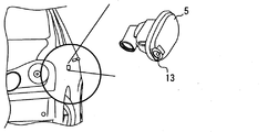
例えば左前方や右前方の送受信マイク13は、自車両の車体の左前方や右前方の位置に、超音波の送波方向が車体の側面から斜め後方を向くように設ける。左前方や右前方の送受信マイク13は、例えば図5に示すように自車両のサイドマーカー5と一体化して設けられる構成としてもよい。なお、左前方や右前方の送受信マイク13は、サイドマーカーの位置の他にも、ドアミラーの近傍の位置等に設ける構成としてもよい。
For example, the left and right front and right transmission /
左後方や右後方の送受信マイク13は、例えば、ルームミラーといった室内後写鏡の死角の範囲に存在する後側方の障害物を検出可能なように、超音波の送波方向が室内後写鏡の死角の範囲と重なるように設ける。ここで言うところの室内後写鏡の死角とは、自車両の運転席に着座したドライバが室内後写鏡で確認できる視覚範囲外の領域を示す。
The left / rear and right / back transmission /
例えば左後方の送受信マイク13は自車両の車体の左後方のコーナー部に、右後方の送受信マイク13は自車両の車体の右後方のコーナー部に、超音波の送波方向が車体の側面から斜め後方を向くように設ける。
For example, the left rear transmission /
図2に戻って、ステップS3では、障害物有無判定処理を行い、ステップS4に移る。障害物有無判定処理では、受信波増幅回路14で増幅された受信波の振幅成分が閾値を超えているか否かを障害物有無判定回路15が判定する。ここで言うところの振幅成分は、受信波の全振幅値であってもよいし、受信波の片振幅値であってもよい。また、ここで言うところの所定の閾値は、少なくともノイズの全振幅値や片振幅値よりも大きい値であればよく、任意に設定可能な値である。
Returning to FIG. 2, in step S3, an obstacle presence / absence determination process is performed, and the process proceeds to step S4. In the obstacle presence / absence determination processing, the obstacle presence /
障害物有無判定回路15は、受信波の大きさが所定の閾値を超えているか否かの判定結果を制御装置11へ出力する。制御装置11では、障害物有無判定回路15での判定結果をもとに、障害物が存在する(障害物あり)か否かを判定する。詳しくは、受信波の大きさが所定の閾値を超えていることを示す判定結果が入力された場合には障害物ありと判定し、受信波の大きさが所定の閾値を超えていないことを示す判定結果が入力された場合には障害物なしと判定する。よって、制御装置11が請求項の障害物有無判定手段に相当する。
The obstacle presence /
本実施形態では、自車両の周囲の多様な方向に存在する障害物を検出することができるように複数の送受信マイク13を採用しているので、どの送受信マイク13の受信波であるかによって、障害物の方向も判定するものとしてもよい。例えば、左前方の送受信マイク13の受信波であった場合には、左側方に障害物ありと判定し、右前方の送受信マイク13の受信波であった場合には、右側方に障害物ありと判定する。また、左後方の送受信マイク13の受信波であった場合には、左斜め後ろに障害物ありと判定し、右後方の送受信マイク13の受信波であった場合には、右斜め後ろに障害物ありと判定する。
In this embodiment, since a plurality of transmission /
ステップS4では、制御装置11で障害物ありと判定した場合(ステップS4でYES)には、ステップS5に移る。また、制御装置11で障害物なしと判定した場合(ステップS4でNO)には、ステップS10に移る。 In step S4, when the control device 11 determines that there is an obstacle (YES in step S4), the process proceeds to step S5. If the controller 11 determines that there is no obstacle (NO in step S4), the process proceeds to step S10.
ステップS5では、距離算出処理を実行し、ステップS6に移る。距離算出処理では、制御装置11から得られる送信波を送波した時間と障害物有無判定回路15から得られる当該送信波の反射波を受波した時間との時間差である送受信時間差を時間差測定回路16が算出し、制御装置11へ出力する。制御装置11は、時間差測定回路16から入力される時間差と超音波の音速とに基づいて障害物との距離を算出する。よって、制御装置11が請求項の距離算出手段に相当する。算出される距離は、例えば送受信マイク13と障害物との間の距離とする。
In step S5, a distance calculation process is executed, and the process proceeds to step S6. In the distance calculation process, a transmission / reception time difference, which is a time difference between the time when the transmission wave obtained from the control device 11 is transmitted and the time when the reflected wave of the transmission wave obtained from the obstacle presence /
ここで、送信波を送波した時間(以下、送波時間)と当該送信波の反射波を受波した時間(以下、受波時間)との一例について図6を用いて説明を行う。図6は、送波時間と受波時間とを説明するための模式図である。図6に示すように、送波時間は、例えば送信パルス発生器12から圧電素子13aへの電圧パルス(つまり、送信駆動波)の供給を開始した時間であり、受波時間は、例えば反射波を受波して得られた受信波の振幅成分が最初に前述の閾値を越えた時間であるものとする。
Here, an example of a time for transmitting a transmission wave (hereinafter referred to as a transmission time) and a time for receiving a reflected wave of the transmission wave (hereinafter referred to as a reception time) will be described with reference to FIG. FIG. 6 is a schematic diagram for explaining a transmission time and a reception time. As shown in FIG. 6, the transmission time is, for example, the time when the supply of the voltage pulse (ie, transmission drive wave) from the
ステップS6では、相対速度範囲演算処理を実行し、ステップS7に移る。相対速度範囲演算処理では、送信波の周波数と同期した周波数の基準信号と障害物有無判定回路15を介して受信波増幅回路14から入力される受信波とをもとに、相対速度範囲判定回路17が当該基準信号に対する当該受信波の位相反転回数をカウントして制御装置11へ入力する。ここで、基準信号については、例えば送信駆動波の角周波数に同期した角周波数の矩形波を図示しない公知の矩形波発生器によって発生させ、その矩形波を基準信号として相対速度範囲判定回路17に入力する構成とすればよい。
In step S6, a relative speed range calculation process is executed, and the process proceeds to step S7. In the relative speed range calculation processing, a relative speed range determination circuit is based on a reference signal having a frequency synchronized with the frequency of the transmission wave and a reception wave input from the reception
相対速度範囲判定回路17での処理を詳しく説明すると以下の通りである。まず、相対速度範囲判定回路17では、入力された受信波の各波が閾値を超えているか否かに応じて2値化することで受信2値化信号を得る。受信波から受信2値化信号を得るのには、例えば公知のコンパレータを用いるなどすればよい。 The processing in the relative speed range determination circuit 17 will be described in detail as follows. First, the relative velocity range determination circuit 17 obtains a received binarized signal by binarizing according to whether or not each wave of the received received wave exceeds a threshold value. In order to obtain the received binary signal from the received wave, for example, a known comparator may be used.
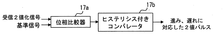
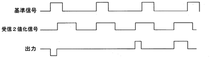
続いて、相対速度範囲判定回路17では、図7に示すように受信2値化信号と基準信号との位相比較を行い、基準信号の位相に対する受信2値化信号の位相の進みと遅れとに対応した2値パルスを得る。よって、相対速度範囲判定回路17が請求項の2値パルス生成手段に相当する。例えば、相対速度範囲判定回路17では、図8に示すように、位相比較器17aとヒステリシス付きコンパレータ17bを用いる構成とすることによって、基準信号と受信2値化信号とから、基準信号の位相に対する受信2値化信号の位相の進みと遅れとに対応した2値パルスを得る。
Subsequently, as shown in FIG. 7, the relative speed range determination circuit 17 compares the phase of the received binarized signal with the reference signal, and determines the phase advance and delay of the received binarized signal with respect to the phase of the reference signal. A corresponding binary pulse is obtained. Therefore, the relative speed range determination circuit 17 corresponds to the binary pulse generating means. For example, as shown in FIG. 8, the relative speed range determination circuit 17 uses a
位相比較器17aは、位相差を比較して、その比較結果に基づいて正負のパルスを選択的に出力する公知の位相比較器を用いる構成とすればよい。例えば図9に示すように、基準信号の位相に対して受信2値化信号の位相が進んでいた場合に正のパルスを出力し、基準信号の位相に対して受信2値化信号の位相が遅れていた場合に負のパルスを出力する位相比較器を用いればよい。これによればヒステリシス付きコンパレータ17bによって、基準信号の位相に対する受信2値化信号の位相の進みと遅れとに対応した2値パルスを得ることができる。
The
また、相対速度範囲判定回路17では、得られた2値パルスの所定時間におけるパルス数をカウントし、カウントしたカウント値を制御装置11へ出力する。よって、相対速度範囲判定回路17は請求項のカウント手段にも相当する。このカウント値が前述の位相反転回数に相当する。なお、ここで言うところの所定時間とは、任意に設定可能な値である。また、パルス数とは、例えばパルスの立ち上がりから立下りまでの繰り返しの回数であってもよいし、パルスの立ち上がりの回数であってもよいし、パルスの立下りの回数であってもよい。 Further, the relative speed range determination circuit 17 counts the number of pulses of the obtained binary pulse in a predetermined time, and outputs the counted value to the control device 11. Therefore, the relative speed range determination circuit 17 corresponds to the counting means in the claims. This count value corresponds to the number of phase inversions described above. Note that the predetermined time here is a value that can be arbitrarily set. The number of pulses may be, for example, the number of repetitions from the rise to the fall of the pulse, the number of rises of the pulse, or the number of fall of the pulse.
障害物で反射された反射波の周波数は、ドップラー効果によってその障害物の相対速度が大きいほど基準信号の周波数からずれるので、障害物の相対速度が大きいほど反射波の位相は、基準信号の位相に対して一定の時間内における進みや遅れの頻度が増加することになる。つまり、障害物の相対速度が大きいほど上記カウント値は大きい値になり、障害物の相対速度が小さいほど上記カウント値は小さい値になる。よって、上記カウント値は障害物の相対速度の指標となる。 The frequency of the reflected wave reflected by the obstacle shifts from the reference signal frequency as the obstacle's relative velocity increases due to the Doppler effect, so the phase of the reflected wave becomes the phase of the reference signal as the obstacle's relative velocity increases. On the other hand, the frequency of advance and delay within a certain time increases. That is, the greater the relative speed of the obstacle, the larger the count value, and the smaller the relative speed of the obstacle, the smaller the count value. Therefore, the count value is an indicator of the relative speed of the obstacle.
ステップS7では、並走車両検出処理を実行し、ステップS8に移る。並走車両検出処理では、距離算出処理で算出された障害物との距離と相対速度範囲演算処理で得られたカウント値とをもとに、自車両の並走車両を検出したか否かを制御装置11が判断する。よって、制御装置11が請求項の検出手段に相当する。 In step S7, a parallel running vehicle detection process is executed, and the process proceeds to step S8. In the parallel running vehicle detection process, it is determined whether or not the parallel running vehicle of the host vehicle is detected based on the distance from the obstacle calculated in the distance calculation process and the count value obtained in the relative speed range calculation process. The control device 11 determines. Therefore, the control device 11 corresponds to detection means in claims.
詳しくは、障害物との距離が所定距離以内であって、且つ、カウント値が第1設定値以下である場合に、並走車両を検出したと判断する。一方、障害物との距離が所定距離以内でない、もしくはカウント値が第1設定値以下でない場合には、並走車両を検出したと判断しない。よって、制御装置11が請求項の第1閾値判定手段に相当し、第1設定値が請求項の第1の閾値に相当する。並走車両検出処理では、カウント値が第1設定値以下であるか否かによって、相対速度が一定値以下の障害物か否かを判断し、並走車両の検出に利用している。 Specifically, it is determined that a parallel running vehicle has been detected when the distance from the obstacle is within a predetermined distance and the count value is equal to or less than the first set value. On the other hand, if the distance from the obstacle is not within the predetermined distance or the count value is not less than or equal to the first set value, it is not determined that the parallel running vehicle has been detected. Therefore, the control device 11 corresponds to the first threshold value determination means in the claims, and the first set value corresponds to the first threshold value in the claims. In the parallel running vehicle detection process, it is determined whether the relative speed is an obstacle with a certain value or less depending on whether the count value is equal to or less than the first set value, and is used for detection of the parallel running vehicle.
ここで言うところの所定距離とは、自車両の運転において注意を払う必要のある車両間の距離を考慮して設定される距離であって、任意に設定可能な値である。この所定距離は、例えば車速センサ2から入力される車速が大きいほど短く設定するなど、車速に応じて制御装置11で設定を変更する構成としてもよい。また、第1設定値とは、どの程度の相対速度の車両までを並走車両として検出するかに応じて設定される値であって、任意に設定可能な値である。
The predetermined distance here is a distance that is set in consideration of the distance between vehicles that need to pay attention in driving the host vehicle, and is a value that can be arbitrarily set. The predetermined distance may be set to be changed by the control device 11 according to the vehicle speed, for example, the predetermined distance is set to be shorter as the vehicle speed input from the
ステップS8では、並走車両検出処理で並走車両を検出したと判断した場合(ステップS8でYES)には、並走車両を検出したものとしてステップS9に移る。また、並走車両を検出したと判断しなかった場合(ステップS8でNO)には、並走車両を検出しなかったものとしてステップS10に移る。 In step S8, when it is determined that the parallel running vehicle is detected in the parallel running vehicle detection process (YES in step S8), the process proceeds to step S9 assuming that the parallel running vehicle is detected. If it is not determined that a parallel running vehicle has been detected (NO in step S8), it is determined that no parallel running vehicle has been detected, and the process proceeds to step S10.
ステップS9では、報知処理を実行し、ステップS10に移る。報知処理では、制御装置11が報知器3に指示を行い、並走車両が存在することを示す報知を行う。よって、制御装置11が請求項の報知手段にも相当する。これによれば、自車両の外部後写鏡や室内後写鏡の死角となる領域の並走車両の存在をドライバが認識することが可能となる。なお、並走車両が存在することを示す報知としては、警報音の出力、案内音声、インジケータ表示、テキスト表示、アイコン表示などがある。また、前述したように障害物の方向を判定していた場合には、並走車両の方向を示す報知も行う構成としてもよい。
In step S9, a notification process is executed, and the process proceeds to step S10. In the notification process, the control device 11 instructs the
ステップS10では、機能選択オフになった場合(ステップS10でYES)には、フローを終了する。また、機能選択オンのままであった場合(ステップS10でNO)には、ステップS1に戻ってフローを繰り返す。 In step S10, when the function selection is turned off (YES in step S10), the flow ends. If the function selection remains on (NO in step S10), the process returns to step S1 and the flow is repeated.
以上の構成によれば、障害物有無判定で存在すると判定された障害物の相対速度の指標となるカウント値が第1設定値以下であるか否かをもとに、並走車両を検出したか否かを判定するので、相対速度が小さい並走車両の存在を精度良く検出することができる。また、障害物との距離も考慮して並走車両の存在を検出したか否かを判定するので、自車両の運転において注意を払う必要のない距離に存在する車両を検出せずに済み、並走車両の検出精度をより高めることが可能になる。 According to the above configuration, the parallel running vehicle is detected based on whether or not the count value serving as an index of the relative speed of the obstacle determined to be present in the obstacle presence / absence determination is equal to or less than the first set value. Therefore, it is possible to accurately detect the presence of a parallel running vehicle having a small relative speed. In addition, since it is determined whether or not the presence of the parallel running vehicle is detected in consideration of the distance to the obstacle, it is not necessary to detect a vehicle that exists at a distance where it is not necessary to pay attention in driving the vehicle. It becomes possible to further improve the detection accuracy of the parallel running vehicle.
さらに、障害物の相対速度の指標となるカウント値は、基準信号の位相と反射波(詳しくは受信波)の位相とを比較し、基準信号に対する位相の進みと遅れとに対応した2値パルスを生成して、所定時間におけるパルス数をカウントすれば得られる。位相の比較は前述したように位相比較器17aを用いるなどして容易に行うことができるため、周波数分析を行って送信波の周波数と反射波の周波数との差を検出し、この差に基づいて障害物の相対速度を検出する構成に比べ、手間を減らすことができる。
Furthermore, the count value that is an index of the relative speed of the obstacle is a binary pulse corresponding to the phase advance and delay with respect to the reference signal by comparing the phase of the reference signal with the phase of the reflected wave (specifically, the received wave). And the number of pulses in a predetermined time is counted. Since the phase comparison can be easily performed by using the
なお、本実施形態では、障害物検出装置1で並走車両を検出する構成を示したが、必ずしもこれに限らない。例えば、本実施形態で示した4箇所の送受信マイク13に代え、自車両の後方に向けて超音波を送波するように送受信マイク13を設置することによって、自車両の追従車両を検出する構成としてもよい。この場合、送受信マイク13は例えば自車両の後部のバンパに設けるなどすればよい。
In addition, in this embodiment, although the structure which detects a parallel running vehicle with the
また、本実施形態で示した4箇所の送受信マイク13に加え、自車両の後方に向けて超音波を送波するように送受信マイク13を設置することによって、自車両の並走車両および追従車両のいずれかを検出する構成としてもよい。この場合、並走車両であるか追従車両であるかは、どの送受信マイク13で障害物からの反射波を受波したか(どの送受信マイク13の受信波であるか)によって制御装置11で判断する構成とすればよい。
In addition to the four transmission /
このように、以上の構成によれば、カウント値の大小をもとに、並走車両以外の障害物の存在も検出可能となるので汎用性を高くすることも可能になる。その結果、自車両周辺の障害物の検出を、ドップラー効果を利用しながらもより容易に行うことを可能にする汎用性の高い運転支援装置を提供することが可能になる。 As described above, according to the above configuration, it is possible to detect the presence of an obstacle other than the parallel running vehicle based on the magnitude of the count value, so that versatility can be enhanced. As a result, it is possible to provide a highly versatile driving support device that can more easily detect obstacles around the host vehicle while using the Doppler effect.
なお、障害物との相対速度が同じ場合であっても、自車両の車速が小さくなるほど基準信号と反射波との位相差は小さくなり、相対速度範囲判定回路17でパルス数をカウントする時間が一定の場合には、カウント値は小さくなる。よって、相対速度範囲判定回路17でパルス数をカウントする時間が一定の場合には、自車両の車速が小さくなるほど、並走車両や追従車両として検出したい相対速度の障害物以外の反射波から得られるカウント値も第1設定値以下となる可能性が増加する。つまり、障害物検出装置1での並走車両や追従車両の誤検出の可能性が高くなるという問題点がある。
Even when the relative speed with the obstacle is the same, the phase difference between the reference signal and the reflected wave decreases as the vehicle speed of the host vehicle decreases, and the time for counting the number of pulses by the relative speed range determination circuit 17 is reduced. In a fixed case, the count value becomes small. Therefore, when the time for counting the number of pulses in the relative speed range determination circuit 17 is constant, the smaller the vehicle speed of the host vehicle, the less the relative speed desired to be detected as a parallel running vehicle or a following vehicle is obtained from reflected waves other than obstacles. There is an increased possibility that the counted value will be equal to or lower than the first set value. That is, there is a problem that the possibility of erroneous detection of a parallel running vehicle or a following vehicle by the
従って、相対速度範囲判定回路17では、車速センサ2から制御装置11が取得した自車両の車速をもとに、自車両の車速が小さくなるほど前述の所定時間を長く設定する構成とすることが好ましい。よって、制御装置11が請求項の速度情報取得手段に相当する。例えば、自車両の車速が小さくなるのに反比例して前述の所定時間を長く設定するなどの構成とすればよい。これによれば、自車両の車速が小さくなるほどカウントされるパルス数を増やすことが可能になり、上記誤検出を防ぐことが可能になる。
Therefore, it is preferable that the relative speed range determination circuit 17 is configured to set the predetermined time longer as the vehicle speed of the host vehicle decreases based on the vehicle speed of the host vehicle acquired by the control device 11 from the
また、障害物との相対速度が同じ場合であっても、自車両の車速が小さくなるほど基準信号と反射波との位相差は小さくなり、送信波の送信継続時間(つまり、送信駆動波の送信パルス幅(図6参照))が一定の場合であって、上述の所定時間が当該送信波に対する受信波の前述の閾値以上のピークを全てカバーする程度に長く設定されている場合には、カウント値は小さくなる。よって、送信駆動波の送信パルス幅が一定の場合には、自車両の車速が小さくなるほど並走車両や追従車両の誤検出の可能性が高くなるという問題点がある。 Even if the relative speed with the obstacle is the same, the phase difference between the reference signal and the reflected wave decreases as the vehicle speed of the host vehicle decreases, and the transmission duration of the transmission wave (that is, transmission of the transmission drive wave) If the pulse width (see FIG. 6) is constant and the predetermined time is set to be long enough to cover all the peaks of the reception wave with respect to the transmission wave that are equal to or greater than the threshold value, the count is performed. The value becomes smaller. Therefore, when the transmission pulse width of the transmission drive wave is constant, there is a problem that the possibility of erroneous detection of a parallel running vehicle or a following vehicle increases as the vehicle speed of the host vehicle decreases.
従って、制御装置11では、車速センサ2から制御装置11が取得した自車両の車速をもとに、自車両の車速が小さくなるほど送信パルス発生器12で発生させる送信駆動波のパルス幅を長くさせることで、自車両の車速が小さくなるほど送信波の送信継続時間を長く設定する構成とすることが好ましい。例えば、自車両の車速が小さくなるのに反比例して送信波の送信継続時間を長く設定するなどの構成とすればよい。これによっても、自車両の車速が小さくなるほどカウントされるパルス数を増やすことが可能になり、上記誤検出を防ぐことが可能になる。
Therefore, in the control device 11, based on the vehicle speed of the host vehicle acquired by the control device 11 from the
以上、本発明の実施形態を説明したが、本発明は上述の実施形態に限定されるものではなく、次の実施形態も本発明の技術的範囲に含まれる。以下では、この次の実施形態について図面を用いて説明を行う。図10は、本発明が適用された運転支援システム200の概略的な構成を示す図である。なお、説明の便宜上、前述の実施形態の説明に用いた図に示した部材と同一の機能を有する部材については、同一の符号を付し、その説明を省略する。
As mentioned above, although embodiment of this invention was described, this invention is not limited to the above-mentioned embodiment, The following embodiment is also contained in the technical scope of this invention. Hereinafter, the next embodiment will be described with reference to the drawings. FIG. 10 is a diagram showing a schematic configuration of a driving
運転支援システム200は、並走車両や追従車両でなく、自車両と接触する危険性のある物体(以下、接触危険性物体)を検出する点が運転支援システム100と異なっている。運転支援システム200は、接触対応装置6を含んでいる点、障害物検出装置1の代わりに障害物検出装置1aを含んでいる点、ならびに送受信マイク13の設置場所および設置方向が異なる点を除けば運転支援システム100と同様の構成である。また、障害物検出装置1aは、制御装置11の代わりに制御装置11aを備えている点を除けば障害物検出装置1と同様の構成である。なお、接触危険性物体は車両や歩行者等の移動体であってもよいし、停車中の車両や静止中の歩行者や電信柱等の静止物体であってもよい。
The driving
接触対応装置6は、自車両と障害物等の障害物との接触の回避を支援したり、自車両と障害物等の障害物とが接触した場合に自車両の乗員を保護したりするための装置である。例えば接触対応装置6は、エンジンECU8に駆動力を低減させたり、ブレーキECU9に制動力を増加させたりして、自車両を減速させて障害物との接触の回避を支援する装置であってもよい。また、接触対応装置6は、ブレーキECU9に制動力を増加させて強制的に自車両を停止させて障害物との接触の回避を支援する装置であってもよい。他にも、障害物との衝突の際にたるんだシートベルトの帯を締めること(以下、シートベルト固定)によって自車両の乗員に対する衝突時の衝撃を緩和し、乗員を保護する装置であってもよい。
The
続いて、図11を用いて、障害物検出装置1aの動作フローについての説明を行う。図11は、障害物検出装置1aの動作フローを示すフローチャートである。本フローは、機能選択スイッチ4で自車両周辺の障害物の検出を行わせる選択が行われた場合にフローを開始する。機能選択スイッチ4で自車両周辺の障害物の検出を行わせる選択が行われている状態を機能選択オンとし、選択が行われなくなった状態を機能選択オフとする。
Subsequently, an operation flow of the
まず、ステップS21では、ステップS1と同様に送信処理を実行してステップS22に移る。ステップS22では、ステップS2と同様に受信処理を実行してステップS23に移る。運転支援システム200では、送受信マイク13を1つだけ採用する構成とすることも可能だが、自車両の周囲の多様な方向に存在する障害物を検出することができるように、複数の送受信マイク13を採用するものとする。
First, in step S21, transmission processing is executed in the same manner as in step S1, and the process proceeds to step S22. In step S22, the reception process is executed in the same manner as in step S2, and the process proceeds to step S23. In the driving
ここで、図12(a)および図12(b)を用いて、運転支援システム200での複数の送受信マイク13の設置場所および設置方向についての説明を行う。図12(a)および図12(b)は運転支援システム200での複数の送受信マイク13の設置場所および設置方向を説明するための模式図である。
Here, with reference to FIG. 12A and FIG. 12B, the installation location and the installation direction of the plurality of transmission /
図12(a)および図12(b)に示すように、運転支援システム200では、2つの送受信マイク13(つまり、超音波センサ)を自車両の車体の前方および後方に設ける。前方の送受信マイク13は、例えば自車両の前方に存在する障害物を検出可能なように、超音波の送波方向を自車両の前方に向けて設ける。前方の送受信マイク13は、例えば自車両の車体前部のバンパ等に設ける構成とすればよい。後方の送受信マイク13は、例えば、自車両の後方に存在する障害物を検出可能なように、超音波の送波方向を自車両の後方に向けて設ける。後方の送受信マイク13は、例えば自車両の車体後部のバンパ等に設ける構成とすればよい。
As shown in FIGS. 12A and 12B, in the driving
図11に戻って、ステップS23では、ステップS3と同様に障害物有無判定処理を行い、ステップS24に移る。よって、制御装置11aが請求項の距離算出手段に相当する。また、本実施形態では、どの送受信マイク13の受信波であるかによって、障害物の方向も判定するものとしてもよい。例えば、前方の送受信マイク13の受信波であった場合には、前方に障害物ありと判定し、後方の送受信マイク13の受信波であった場合には、後方に障害物ありと判定する。
Returning to FIG. 11, in step S23, obstacle presence / absence determination processing is performed in the same manner as in step S3, and the process proceeds to step S24. Therefore, the control device 11a corresponds to the distance calculation means in the claims. In the present embodiment, the direction of the obstacle may be determined according to which transmission /
ステップS24では、制御装置11aで障害物ありと判定した場合(ステップS24でYES)には、ステップS25に移る。また、制御装置11aで障害物なしと判定した場合(ステップS24でNO)には、ステップS31に移る。ステップS25では、ステップS5と同様に距離算出処理を実行し、ステップS26に移る。よって、制御装置11aが請求項の距離算出手段に相当する。ステップS26では、ステップS6と同様に相対速度範囲演算処理を実行し、ステップS27に移る。 In step S24, when the control device 11a determines that there is an obstacle (YES in step S24), the process proceeds to step S25. If the controller 11a determines that there is no obstacle (NO in step S24), the process proceeds to step S31. In step S25, a distance calculation process is executed as in step S5, and the process proceeds to step S26. Therefore, the control device 11a corresponds to the distance calculation means in the claims. In step S26, a relative speed range calculation process is executed as in step S6, and the process proceeds to step S27.
ステップS27では、接触危険性物体検出処理を実行し、ステップS28に移る。接触危険性物体検出処理では、距離算出処理で算出された障害物との距離と相対速度範囲演算処理で得られたカウント値とをもとに、接触危険性物体を検出したか否かを制御装置11aが判断する。よって、制御装置11aが請求項の検出手段に相当する。 In step S27, a contact risk object detection process is executed, and the process proceeds to step S28. In the contact risk detection process, whether or not a contact risk object is detected is controlled based on the distance from the obstacle calculated in the distance calculation process and the count value obtained in the relative speed range calculation process. The device 11a determines. Therefore, the control device 11a corresponds to the detection means in the claims.
詳しくは、障害物との距離が所定距離以内であって、且つ、カウント値が第2設定値以上である場合に、接触危険性物体を検出したと判断する。一方、障害物との距離が所定距離以内でない、もしくはカウント値が第2設定値以上でない場合には、接触危険性物体を検出したと判断しない。よって、制御装置11aが請求項の第2閾値判定手段に相当し、第2設定値が請求項の第2の閾値に相当する。接触危険性物体検出処理では、カウント値が第2設定値以上であるか否かによって、相対速度が一定値以上の障害物か否かを判断し、接触危険性物体の検出に利用している。 Specifically, when the distance from the obstacle is within a predetermined distance and the count value is greater than or equal to the second set value, it is determined that a contact risk object has been detected. On the other hand, if the distance from the obstacle is not within the predetermined distance or the count value is not equal to or greater than the second set value, it is not determined that the contact risk object has been detected. Therefore, the control device 11a corresponds to the second threshold value determining means in the claims, and the second set value corresponds to the second threshold value in the claims. In the contact risk object detection process, it is determined whether the relative speed is an obstacle with a certain value or more depending on whether the count value is equal to or greater than the second set value, and is used to detect the contact risk object. .
ここで言うところの所定距離とは、自車両と障害物との接触の危険性が高いと考えられる距離であって、任意に設定可能な値である。この所定距離は、例えば車速センサ2から入力される車速が大きいほど短く設定するなど、車速に応じて制御装置11aで設定を変更する構成としてもよい。また、第2設定値とは、どの程度の相対速度の車両までを接触危険性物体として検出するかに応じて設定される値であって、任意に設定可能な値である。
The predetermined distance here is a distance that is considered to have a high risk of contact between the host vehicle and the obstacle, and is a value that can be arbitrarily set. The predetermined distance may be set to be changed by the control device 11a according to the vehicle speed, for example, the predetermined distance is set to be shorter as the vehicle speed input from the
ステップS28では、接触危険性物体検出処理で接触危険性物体を検出したと判断した場合(ステップS28でYES)には、接触危険性物体を検出したものとしてステップS29に移る。また、接触危険性物体を検出したと判断しなかった場合(ステップS28でNO)には、接触危険性物体を検出しなかったものとしてステップS31に移る。 If it is determined in step S28 that a contact risk object has been detected in the contact risk object detection process (YES in step S28), the process proceeds to step S29 assuming that a contact risk object has been detected. On the other hand, if it is not determined that a contact risk object has been detected (NO in step S28), it is determined that a contact risk object has not been detected, and the process proceeds to step S31.
ステップS29では、報知処理を実行し、ステップS30に移る。報知処理では、制御装置11が報知器3に指示を行い、接触危険性物体が存在することを示す報知を行う。よって、制御装置11aが請求項の報知手段にも相当する。これによれば、自車両が他車両や歩行者や構造物等に接触する危険性をドライバが認識することが可能となる。なお、接触危険性物体が存在することを示す報知としては、警報音の出力、案内音声、インジケータ表示、テキスト表示、アイコン表示などがある。また、前述したように障害物の方向を判定していた場合には、接触危険性物体の方向を示す報知も行う構成としてもよい。
In step S29, a notification process is executed, and the process proceeds to step S30. In the notification process, the control device 11 instructs the
ステップS30では、接触対応処理を実行し、ステップS31に移る。接触対応処理では、制御装置11aが接触対応装置6を作動させ、自車両の減速や強制停止によって接触危険性物体との接触の回避を支援したり、シートベルト固定によって接触危険性物体との接触時の乗員に対する衝撃を緩和させたりする。よって、制御装置11aが請求項の接触対応手段に相当する。また、前述したように障害物の方向を判定していた場合には、障害物の方向に応じた処理を行わせる構成とすればよい。例えば、前方に障害物ありと判定していた場合には、自車両の減速や強制停止やシートベルト固定を行わせる一方、後方に障害物ありと判定していた場合には、シートベルト固定を行わせるが自車両の減速や強制停止は行わせないなどする構成としてもよい。
In step S30, a contact handling process is executed, and the process proceeds to step S31. In the contact handling process, the control device 11a activates the
ステップS31では、機能選択オフになった場合(ステップS31でYES)には、フローを終了する。また、機能選択オンのままであった場合(ステップS31でNO)には、ステップS21に戻ってフローを繰り返す。 In step S31, when the function selection is turned off (YES in step S31), the flow ends. If the function selection remains on (NO in step S31), the process returns to step S21 to repeat the flow.
以上の構成によれば、障害物有無判定で存在すると判定された障害物の相対速度の指標となるカウント値が第2設定値以上であるか否かをもとに、接触危険性物体を検出したか否かを判定するので、相対速度が大きい接触危険性物体の存在を精度良く検出することができる。また、障害物との距離も考慮して接触危険性物体の存在を検出したか否かを判定するので、接触の危険性が低い距離に存在する障害物を検出せずに済み、接触危険性物体の検出精度をより高めることが可能になる。 According to the above configuration, a contact risk object is detected based on whether or not the count value that is an index of the relative speed of the obstacle determined to be present in the obstacle presence / absence determination is equal to or greater than the second set value. Therefore, it is possible to accurately detect the presence of a contact risk object having a high relative speed. In addition, since it is determined whether the presence of a contact risk object is detected in consideration of the distance to the obstacle, it is not necessary to detect an obstacle present at a distance where the contact risk is low. The object detection accuracy can be further increased.
なお、本実施形態では、障害物検出装置1aで前方の接触危険性物体と後方の接触危険性物体との両方を検出可能な構成を示したが、必ずしもこれに限らない。例えば、送受信マイク13を前方のみに設けることで前方の接触危険性物体だけを検出する構成としてもよいし、送受信マイク13を後方のみに設けることで後方の接触危険性物体だけを検出する構成としてもよい。
In the present embodiment, the
このように、以上の構成によっても、カウント値の大小をもとに、並走車両以外の障害物の存在も検出可能となるので汎用性を高くすることも可能になる。その結果、自車両周辺の障害物の検出を、ドップラー効果を利用しながらもより容易に行うことを可能にする汎用性の高い運転支援装置を提供することが可能になる。 As described above, even with the above configuration, it is possible to detect the presence of an obstacle other than the parallel running vehicle on the basis of the size of the count value, so that versatility can be enhanced. As a result, it is possible to provide a highly versatile driving support device that can more easily detect obstacles around the host vehicle while using the Doppler effect.
前述の実施形態では、運転支援システム100および運転支援システム200を示したが、お互い共通する構成については併用することでこれらを組み合わせる構成としてもよい。つまり、カウント値の大小をもとに、1つのシステムで並走車両や追従車両や接触危険性物体を検出する構成としてもよい。
In the above-described embodiment, the driving
また、前述の実施形態では、超音波を用いて障害物を検出する場合を例に挙げたが、必ずしもこれに限らない。本発明は、ドップラー効果により周波数のシフトが生じる探査波であれば超音波以外の探査波も適用可能であって、例えばミリ波等の電磁波や赤外光等の光を探査波として用いる構成としてもよい。 In the above-described embodiment, the case where an obstacle is detected using ultrasonic waves is described as an example, but the present invention is not necessarily limited thereto. The present invention is applicable to exploration waves other than ultrasonic waves as long as the exploration waves cause a frequency shift due to the Doppler effect. For example, electromagnetic waves such as millimeter waves and light such as infrared light are used as exploration waves. Also good.
なお、本発明は、上述した各実施形態に限定されるものではなく、請求項に示した範囲で種々の変更が可能であり、異なる実施形態にそれぞれ開示された技術的手段を適宜組み合わせて得られる実施形態についても本発明の技術的範囲に含まれる。 The present invention is not limited to the above-described embodiments, and various modifications can be made within the scope of the claims, and the technical means disclosed in different embodiments can be appropriately combined. Such embodiments are also included in the technical scope of the present invention.
1・1a 障害物検出装置(運転支援装置)、2 車速センサ、3 報知器、4 機能選択スイッチ、5 サイドマーカー、6 接触対応装置、11 制御装置(送信手段、障害物有無判定手段、距離算出手段、検出手段、第1閾値判定手段、報知手段、速度情報取得手段)、11a 制御装置(送信手段、障害物有無判定手段、距離算出手段、検出手段、第2閾値判定手段、報知手段、接触対応手段)、12 送信パルス発生器(送信手段)、13 送受信マイク(送信手段、受信手段)、14 受信波増幅回路、15 障害物有無判定回路、16 時間差測定回路、17 相対速度範囲判定回路(2値パルス生成手段、カウント手段)、17a 位相比較器、17b ヒステリシス付きコンパレータ、100・200 運転支援システム 1.1a Obstacle detection device (driving support device), 2 vehicle speed sensor, 3 alarm, 4 function selection switch, 5 side marker, 6 contact compatible device, 11 control device (transmission means, obstacle presence / absence determination means, distance calculation) Means, detection means, first threshold determination means, notification means, speed information acquisition means), 11a control device (transmission means, obstacle presence / absence determination means, distance calculation means, detection means, second threshold determination means, notification means, contact Corresponding means), 12 transmission pulse generator (transmission means), 13 transmission / reception microphone (transmission means, reception means), 14 reception wave amplification circuit, 15 obstacle presence / absence determination circuit, 16 time difference measurement circuit, 17 relative velocity range determination circuit ( Binary pulse generating means, counting means), 17a phase comparator, 17b comparator with hysteresis, 100/200 driving support system
Claims (10)
前記車両の周囲に一定の周波数の送信波を逐次送信する送信手段と、
前記送信波の反射波を逐次受信する受信手段と、
前記受信手段で受信した反射波をもとに前記車両の周囲の障害物の存在の有無を判定する障害物有無判定手段と、
前記送信波の周波数と同期した周波数の基準信号の位相と前記受信手段で受信した反射波の位相とを比較し、当該基準信号に対する位相の進みと遅れとに対応した2値パルスを生成する2値パルス生成手段と、
前記2値パルス生成手段で生成した2値パルスの所定時間におけるパルス数をカウントするカウント手段と、
前記障害物有無判定手段で障害物が存在すると判定したこと、および前記カウント手段でカウントしたカウント値をもとに、前記車両の周辺の障害物の存在を検出する検出手段とを備えることを特徴とする運転支援装置。 Mounted on the vehicle,
Transmitting means for sequentially transmitting a transmission wave of a constant frequency around the vehicle;
Receiving means for sequentially receiving the reflected wave of the transmission wave;
An obstacle presence / absence determining means for determining the presence / absence of an obstacle around the vehicle based on the reflected wave received by the receiving means;
The phase of the reference signal having a frequency synchronized with the frequency of the transmission wave is compared with the phase of the reflected wave received by the receiving means, and a binary pulse corresponding to the phase advance and delay with respect to the reference signal is generated 2 Value pulse generating means;
Counting means for counting the number of pulses of the binary pulse generated by the binary pulse generating means at a predetermined time;
And detecting means for detecting the presence of an obstacle around the vehicle based on the count value counted by the counting means determined by the obstacle presence / absence judging means. A driving support device.
前記車両の速度の情報を取得する速度情報取得手段をさらに備え、
前記カウント手段は、
前記速度情報取得手段で取得した前記車両の速度の情報をもとに、前記車両の速度が小さくなるほど前記所定時間を長く設定することを特徴とする運転支援装置。 In claim 1,
It further comprises speed information acquisition means for acquiring information on the speed of the vehicle,
The counting means includes
The driving support apparatus characterized in that the predetermined time is set longer as the vehicle speed decreases based on the vehicle speed information acquired by the speed information acquisition means.
前記車両の速度の情報を取得する速度情報取得手段をさらに備え、
前記送信手段は、
前記速度情報取得手段で取得した前記車両の速度の情報をもとに、前記車両の速度が小さくなるほど送信波の送信継続時間を長く設定することを特徴とする運転支援装置。 In claim 1,
It further comprises speed information acquisition means for acquiring information on the speed of the vehicle,
The transmission means includes
A driving support apparatus, wherein the transmission duration time of the transmission wave is set longer as the vehicle speed decreases based on the vehicle speed information acquired by the speed information acquisition means.
前記カウント手段でカウントしたカウント値を第1の閾値と比較し、カウント値が第1の閾値以下であるか否かを判定する第1閾値判定手段をさらに備え、
前記検出手段は、
前記障害物有無判定手段で障害物が存在すると判定したこと、および前記第1閾値判定手段でカウント値が第1の閾値以下であると判定したことをもとに、前記車両の並走車両および追従車両のいずれかの存在を検出することを特徴とする運転支援装置。 In any one of Claims 1-3,
Comparing the count value counted by the counting means with a first threshold, further comprising first threshold determination means for determining whether the count value is equal to or less than the first threshold,
The detection means includes
Based on the fact that the obstacle presence / absence determining means has determined that an obstacle is present and the first threshold value determining means has determined that the count value is equal to or less than a first threshold value, A driving support device that detects the presence of any of the following vehicles.
前記カウント手段でカウントしたカウント値を第2の閾値と比較し、カウント値が第2の閾値以上であるか否かを判定する第2閾値判定手段をさらに備え、
前記検出手段は、
前記障害物有無判定手段で障害物が存在すると判定したこと、および前記第2閾値判定手段でカウント値が第2の閾値以上であると判定したことをもとに、前記車両に接触する危険性のある物体である接触危険性物体の存在を検出することを特徴とする運転支援装置。 In claim 1,
Comparing the count value counted by the counting means with a second threshold, further comprising second threshold determination means for determining whether the count value is equal to or greater than the second threshold,
The detection means includes
Risk of contact with the vehicle based on the fact that the obstacle presence / absence judging means judges that an obstacle is present and the second threshold judging means judges that the count value is greater than or equal to a second threshold A driving support apparatus that detects the presence of a contact risk object that is an object.
前記カウント手段でカウントしたカウント値を第1の閾値と比較し、カウント値が第1の閾値以下であるか否かを判定する第1閾値判定手段と、
前記カウント手段でカウントしたカウント値を第2の閾値と比較し、カウント値が第2の閾値以上であるか否かを判定する第2閾値判定手段とをさらに備え、
前記検出手段は、
前記障害物有無判定手段で障害物が存在すると判定したこと、および前記第1閾値判定手段でカウント値が第1の閾値以下であると判定したことをもとに、前記車両の並走車両および追従車両のいずれかの存在を検出する一方、前記障害物有無判定手段で障害物が存在すると判定したこと、および前記第2閾値判定手段でカウント値が第2の閾値以上であると判定したことをもとに、前記車両に接触する危険性のある物体である接触危険性物体の存在を検出することを特徴とする運転支援装置。 In any one of Claims 1-3,
A first threshold value determining means for comparing the count value counted by the counting means with a first threshold value and determining whether the count value is equal to or less than the first threshold value;
A second threshold determination unit that compares the count value counted by the counting unit with a second threshold and determines whether the count value is equal to or greater than the second threshold;
The detection means includes
Based on the fact that the obstacle presence / absence determining means has determined that an obstacle is present and the first threshold value determining means has determined that the count value is equal to or less than a first threshold value, While detecting the presence of any of the following vehicles, determining that the obstacle is present by the obstacle presence / absence determining means, and determining that the count value is greater than or equal to the second threshold by the second threshold determining means Based on the above, a driving assistance device that detects the presence of a contact risk object that is a risk object that contacts the vehicle.
前記検出手段で前記接触危険性物体の存在を検出した場合に、前記車両と前記接触危険性物体との接触の回避の支援、および前記車両と前記接触危険性物体とが接触した場合に前記車両の乗員を保護するための装置の作動の少なくともいずれを行う接触対応手段をさらに備えることを特徴とする運転支援装置 In claim 5 or 6,
When the detection means detects the presence of the contact risk object, the vehicle avoids the contact between the vehicle and the contact risk object, and the vehicle and the contact risk object come into contact with each other. A driving support device further comprising contact handling means for performing at least one of operations of the device for protecting the passenger of the vehicle
前記送信波を送信した時間とその送信波の反射波を受信した時間との差に基づいて、障害物までの距離を算出する距離算出手段をさらに備え、
前記検出手段は、
前記障害物有無判定手段で障害物が存在すると判定したこと、および前記第1閾値判定手段でカウント値が第1の閾値以下であると判定したことに加え、前記距離算出手段で算出した障害物までの距離をもとにして、前記車両の並走車両および追従車両のいずれかの存在を検出することを特徴とする運転支援装置。 In claim 4 or 6,
Based on the difference between the time when the transmission wave is transmitted and the time when the reflected wave of the transmission wave is received, further comprising distance calculation means for calculating the distance to the obstacle,
The detection means includes
In addition to determining that there is an obstacle by the obstacle presence / absence determining means, and determining that the count value is equal to or less than the first threshold value by the first threshold determining means, the obstacle calculated by the distance calculating means A driving support apparatus that detects the presence of either the parallel running vehicle or the following vehicle of the vehicle based on the distance to the vehicle.
前記送信波を送信した時間とその送信波の反射波を受信した時間との差に基づいて、障害物までの距離を算出する距離算出手段をさらに備え、
前記検出手段は、
前記障害物有無判定手段で障害物が存在すると判定したこと、および前記第2閾値判定手段でカウント値が第2の閾値以上であると判定したことに加え、前記距離算出手段で算出した障害物までの距離をもとにして、前記接触危険性物体の存在を検出することを特徴とする運転支援装置。 In any one of Claims 5-7,
Based on the difference between the time when the transmission wave is transmitted and the time when the reflected wave of the transmission wave is received, further comprising distance calculation means for calculating the distance to the obstacle,
The detection means includes
In addition to determining that there is an obstacle by the obstacle presence / absence determining means, and determining that the count value is greater than or equal to a second threshold value by the second threshold determining means, the obstacle calculated by the distance calculating means A driving support device that detects the presence of the contact risk object based on the distance to the vehicle.
前記検出手段での検出結果に応じた報知を行う報知手段をさらに備えることを特徴とする運転支援装置。 In any one of Claims 1-9,
The driving support device further comprising notification means for performing notification according to the detection result of the detection means.
Priority Applications (2)
| Application Number | Priority Date | Filing Date | Title |
|---|---|---|---|
| JP2011056676A JP5338829B2 (en) | 2011-03-15 | 2011-03-15 | Driving assistance device |
| US13/418,436 US8823578B2 (en) | 2011-03-15 | 2012-03-13 | Driving assist apparatus |
Applications Claiming Priority (1)
| Application Number | Priority Date | Filing Date | Title |
|---|---|---|---|
| JP2011056676A JP5338829B2 (en) | 2011-03-15 | 2011-03-15 | Driving assistance device |
Publications (2)
| Publication Number | Publication Date |
|---|---|
| JP2012194656A true JP2012194656A (en) | 2012-10-11 |
| JP5338829B2 JP5338829B2 (en) | 2013-11-13 |
Family
ID=46828019
Family Applications (1)
| Application Number | Title | Priority Date | Filing Date |
|---|---|---|---|
| JP2011056676A Active JP5338829B2 (en) | 2011-03-15 | 2011-03-15 | Driving assistance device |
Country Status (2)
| Country | Link |
|---|---|
| US (1) | US8823578B2 (en) |
| JP (1) | JP5338829B2 (en) |
Cited By (2)
| Publication number | Priority date | Publication date | Assignee | Title |
|---|---|---|---|---|
| US9599710B2 (en) | 2012-07-06 | 2017-03-21 | Nippon Soken, Inc. | Adjacent vehicle detection device |
| JP2023151509A (en) * | 2022-03-31 | 2023-10-16 | 古河As株式会社 | Radar device, notification determination method and program |
Families Citing this family (7)
| Publication number | Priority date | Publication date | Assignee | Title |
|---|---|---|---|---|
| JP5905846B2 (en) * | 2013-03-29 | 2016-04-20 | 株式会社日本自動車部品総合研究所 | Crossing determination device and program |
| US9751527B2 (en) * | 2014-07-09 | 2017-09-05 | Alcatel-Lucent Usa Inc. | In-the-road, passable obstruction avoidance arrangement |
| KR101977090B1 (en) * | 2015-07-22 | 2019-05-10 | 엘지전자 주식회사 | Control device for vehicle and method for controlling vehicle |
| WO2017095951A1 (en) * | 2015-11-30 | 2017-06-08 | Nike Innovate C.V. | Apparel with ultrasonic position sensing and haptic feedback for activities |
| US10539672B2 (en) * | 2016-12-09 | 2020-01-21 | GM Global Technology Operations LLC | Doppler ambiguity resolution at high signal to noise ratio |
| CN111862631B (en) * | 2019-05-24 | 2022-07-29 | 北京骑胜科技有限公司 | Vehicle running detection method and device, electronic equipment and readable storage medium |
| JP7708606B2 (en) * | 2021-08-03 | 2025-07-15 | 株式会社Subaru | Object recognition device, computer program, and recording medium |
Citations (4)
| Publication number | Priority date | Publication date | Assignee | Title |
|---|---|---|---|---|
| JPS6090040U (en) * | 1983-11-28 | 1985-06-20 | 関東自動車工業株式会社 | Side mirror with blind spot prevention device |
| JPH0640886U (en) * | 1992-10-30 | 1994-05-31 | 日新電機株式会社 | Speed detector |
| JPH11259634A (en) * | 1998-03-12 | 1999-09-24 | Mitsubishi Motors Corp | Optical flow type backward information detection device |
| JP2006309623A (en) * | 2005-04-28 | 2006-11-09 | Aquaheim:Kk | Collision warning equipment and vehicle using the same |
Family Cites Families (33)
| Publication number | Priority date | Publication date | Assignee | Title |
|---|---|---|---|---|
| US3152326A (en) * | 1959-10-02 | 1964-10-06 | Bendix Corp | Vehicle radar system |
| US3176294A (en) * | 1959-10-02 | 1965-03-30 | Bendix Corp | Vehicle radar system |
| US3779645A (en) * | 1970-05-20 | 1973-12-18 | Nippon Kogaku Kk | Distance measuring device |
| US3730628A (en) * | 1970-12-16 | 1973-05-01 | Martin Marietta Corp | Electronic distance measuring method and apparatus |
| US3716833A (en) * | 1971-12-02 | 1973-02-13 | Sperry Rand Corp | Vehicle height clearance indicating apparatus |
| US3772690A (en) * | 1971-12-07 | 1973-11-13 | Sperry Rand Corp | Vehicle safety apparatus |
| US3789950A (en) * | 1972-03-08 | 1974-02-05 | Sperry Rand Corp | Vehicle protective apparatus |
| US3809477A (en) * | 1972-11-01 | 1974-05-07 | Us Interior | Measuring apparatus for spatially modulated reflected beams |
| JPS6045377B2 (en) | 1976-08-03 | 1985-10-09 | 日産自動車株式会社 | Collision prevention device |
| US6211812B1 (en) * | 1982-12-10 | 2001-04-03 | Alliedsignal Inc. | Quiet radar method and apparatus |
| US5134411A (en) * | 1990-07-13 | 1992-07-28 | General Microwave Corporation | Near range obstacle detection and ranging aid |
| JPH063445A (en) | 1992-06-18 | 1994-01-11 | Mitsubishi Motors Corp | Ultrasonic receiver and obstacle detector |
| JPH06203299A (en) | 1993-01-04 | 1994-07-22 | Takayuki Kadaka | Other vehicle condition informing device |
| JP3431733B2 (en) | 1995-03-30 | 2003-07-28 | 三菱自動車工業株式会社 | Object detection device |
| JPH08268189A (en) | 1995-03-30 | 1996-10-15 | Mitsubishi Motors Corp | Parallel vehicle detection device |
| DE19517001A1 (en) * | 1995-05-09 | 1996-11-14 | Sick Optik Elektronik Erwin | Method and device for determining the light propagation time over a measuring section arranged between a measuring device and a reflecting object |
| US5742379A (en) * | 1995-11-29 | 1998-04-21 | Reifer; Michael H. | Device and method for electronically measuring distances |
| US5757848A (en) * | 1995-11-30 | 1998-05-26 | Motorola, Inc. | Method and apparatus for a decimating digital PN correlator |
| US5731781A (en) * | 1996-05-20 | 1998-03-24 | Delco Electronics Corp. | Continuous wave wideband precision ranging radar |
| US5889490A (en) * | 1996-08-05 | 1999-03-30 | Wachter; Eric A. | Method and apparatus for improved ranging |
| DE19701803A1 (en) * | 1997-01-20 | 1998-10-01 | Sick Ag | Light sensor with light transit time evaluation |
| US6122602A (en) * | 1997-05-02 | 2000-09-19 | Endress + Hauser Gmbh + Co. | Method and arrangement for electromagnetic wave distance measurement by the pulse transit time method |
| US6002342A (en) * | 1997-11-21 | 1999-12-14 | Motorola, Inc. | Communication system and device having unit locating feature |
| US6133993A (en) * | 1998-01-26 | 2000-10-17 | Trw Inc. | Length and velocity measurement apparatus |
| GB2342251A (en) * | 1998-09-29 | 2000-04-05 | Secr Defence | Proximity measuring apparatus |
| EP1067361A1 (en) * | 1999-07-06 | 2001-01-10 | Datalogic S.P.A. | Method and a device for measuring the distance of an object |
| JP3703689B2 (en) * | 2000-06-01 | 2005-10-05 | 三菱電機株式会社 | Obstacle detection device and obstacle detection system |
| US6462705B1 (en) * | 2000-08-17 | 2002-10-08 | Mcewan Technologies, Llc | Spread spectrum radar clock |
| DE10100417A1 (en) * | 2001-01-08 | 2002-07-11 | Bosch Gmbh Robert | Radar device and method for coding a radar device |
| DE10104022A1 (en) * | 2001-01-31 | 2002-08-01 | Bosch Gmbh Robert | Radar device and method for coding a radar device |
| JP4378897B2 (en) * | 2001-05-14 | 2009-12-09 | 株式会社デンソー | Distance measuring device |
| US6864834B2 (en) * | 2003-01-31 | 2005-03-08 | The Ohio State University | Radar system using random RF noise |
| JP4707363B2 (en) * | 2004-10-20 | 2011-06-22 | 株式会社 ソキア・トプコン | Light wave distance meter |
-
2011
- 2011-03-15 JP JP2011056676A patent/JP5338829B2/en active Active
-
2012
- 2012-03-13 US US13/418,436 patent/US8823578B2/en active Active
Patent Citations (4)
| Publication number | Priority date | Publication date | Assignee | Title |
|---|---|---|---|---|
| JPS6090040U (en) * | 1983-11-28 | 1985-06-20 | 関東自動車工業株式会社 | Side mirror with blind spot prevention device |
| JPH0640886U (en) * | 1992-10-30 | 1994-05-31 | 日新電機株式会社 | Speed detector |
| JPH11259634A (en) * | 1998-03-12 | 1999-09-24 | Mitsubishi Motors Corp | Optical flow type backward information detection device |
| JP2006309623A (en) * | 2005-04-28 | 2006-11-09 | Aquaheim:Kk | Collision warning equipment and vehicle using the same |
Cited By (4)
| Publication number | Priority date | Publication date | Assignee | Title |
|---|---|---|---|---|
| US9599710B2 (en) | 2012-07-06 | 2017-03-21 | Nippon Soken, Inc. | Adjacent vehicle detection device |
| US10656269B2 (en) | 2012-07-06 | 2020-05-19 | Soken, Inc. | Adjacent vehicle detection device |
| JP2023151509A (en) * | 2022-03-31 | 2023-10-16 | 古河As株式会社 | Radar device, notification determination method and program |
| JP7847467B2 (en) | 2022-03-31 | 2026-04-17 | 古河As株式会社 | Radar device, notification and determination method, and program |
Also Published As
| Publication number | Publication date |
|---|---|
| US8823578B2 (en) | 2014-09-02 |
| US20120235852A1 (en) | 2012-09-20 |
| JP5338829B2 (en) | 2013-11-13 |
Similar Documents
| Publication | Publication Date | Title |
|---|---|---|
| JP5338829B2 (en) | Driving assistance device | |
| JP4880712B2 (en) | Obstacle detection device | |
| JP3645988B2 (en) | Vehicle obstacle detection device | |
| KR101716590B1 (en) | Method for the improved activation of ultrasonic sensors, driver assistance device and motor vehicle | |
| JP5177510B2 (en) | Ultrasonic sensor | |
| JP6413097B2 (en) | Object detection device | |
| JP4559626B2 (en) | Alarm system for automobile | |
| JP6089585B2 (en) | Obstacle detection device | |
| CN107298098B (en) | Parking assisting device and parking control method thereof | |
| JP5904280B2 (en) | Vehicle alarm device | |
| JP6412469B2 (en) | Driving support device and driving support method | |
| WO2015040815A1 (en) | Object detection device and object detection system | |
| US9869765B2 (en) | Alarm system and method for vehicle | |
| KR102228393B1 (en) | Rear collision warning control method and apparatus | |
| KR20190012851A (en) | Apparatus and method for preventing vehicle collision | |
| JP2011086204A (en) | Traveling safety device for vehicle | |
| JP2013061690A (en) | Obstacle detection system for vehicle | |
| KR101019608B1 (en) | Car collision warning | |
| KR20140078872A (en) | The integrated controlling method and device for blind spot warning and parking assistance | |
| US20150097702A1 (en) | Blind spot sensing apparatus and method | |
| KR101826377B1 (en) | Apparatus and method for alarming danger of vehicle | |
| JP5754420B2 (en) | Vehicle alarm device | |
| KR20150087737A (en) | Vehicular Danger Detecting System | |
| JP2007003369A (en) | Collision determination device | |
| JP5259542B2 (en) | Vehicle travel safety device |
Legal Events
| Date | Code | Title | Description |
|---|---|---|---|
| A621 | Written request for application examination |
Free format text: JAPANESE INTERMEDIATE CODE: A621 Effective date: 20121203 |
|
| A977 | Report on retrieval |
Free format text: JAPANESE INTERMEDIATE CODE: A971007 Effective date: 20130408 |
|
| A131 | Notification of reasons for refusal |
Free format text: JAPANESE INTERMEDIATE CODE: A131 Effective date: 20130423 |
|
| A521 | Request for written amendment filed |
Free format text: JAPANESE INTERMEDIATE CODE: A523 Effective date: 20130612 |
|
| TRDD | Decision of grant or rejection written | ||
| A01 | Written decision to grant a patent or to grant a registration (utility model) |
Free format text: JAPANESE INTERMEDIATE CODE: A01 Effective date: 20130709 |
|
| A61 | First payment of annual fees (during grant procedure) |
Free format text: JAPANESE INTERMEDIATE CODE: A61 Effective date: 20130722 |
|
| R150 | Certificate of patent or registration of utility model |
Ref document number: 5338829 Country of ref document: JP Free format text: JAPANESE INTERMEDIATE CODE: R150 Free format text: JAPANESE INTERMEDIATE CODE: R150 |
|
| R250 | Receipt of annual fees |
Free format text: JAPANESE INTERMEDIATE CODE: R250 |
|
| R250 | Receipt of annual fees |
Free format text: JAPANESE INTERMEDIATE CODE: R250 |
|
| R250 | Receipt of annual fees |
Free format text: JAPANESE INTERMEDIATE CODE: R250 |
|
| R250 | Receipt of annual fees |
Free format text: JAPANESE INTERMEDIATE CODE: R250 |
|
| R250 | Receipt of annual fees |
Free format text: JAPANESE INTERMEDIATE CODE: R250 |
|
| R250 | Receipt of annual fees |
Free format text: JAPANESE INTERMEDIATE CODE: R250 |
|
| R250 | Receipt of annual fees |
Free format text: JAPANESE INTERMEDIATE CODE: R250 |
|
| R250 | Receipt of annual fees |
Free format text: JAPANESE INTERMEDIATE CODE: R250 |
|
| R250 | Receipt of annual fees |
Free format text: JAPANESE INTERMEDIATE CODE: R250 |
|
| R250 | Receipt of annual fees |
Free format text: JAPANESE INTERMEDIATE CODE: R250 |