JP2012194914A - Position detection device, display system with input function, and position detection method - Google Patents

Position detection device, display system with input function, and position detection method Download PDF

Info

Publication number
JP2012194914A
JP2012194914A JP2011059800A JP2011059800A JP2012194914A JP 2012194914 A JP2012194914 A JP 2012194914A JP 2011059800 A JP2011059800 A JP 2011059800A JP 2011059800 A JP2011059800 A JP 2011059800A JP 2012194914 A JP2012194914 A JP 2012194914A
Authority
JP
Japan
Prior art keywords
light
detection
light source
current value
unit
Prior art date
Legal status (The legal status is an assumption and is not a legal conclusion. Google has not performed a legal analysis and makes no representation as to the accuracy of the status listed.)
Withdrawn
Application number
JP2011059800A
Other languages
Japanese (ja)
Inventor
Masateru Takahashi
正輝 高橋
Yasunori Onishi
康憲 大西
Current Assignee (The listed assignees may be inaccurate. Google has not performed a legal analysis and makes no representation or warranty as to the accuracy of the list.)
Seiko Epson Corp
Original Assignee
Seiko Epson Corp
Priority date (The priority date is an assumption and is not a legal conclusion. Google has not performed a legal analysis and makes no representation as to the accuracy of the date listed.)
Filing date
Publication date
Application filed by Seiko Epson Corp filed Critical Seiko Epson Corp
Priority to JP2011059800A priority Critical patent/JP2012194914A/en
Publication of JP2012194914A publication Critical patent/JP2012194914A/en
Withdrawn legal-status Critical Current

Links

Images

Landscapes

  • Length Measuring Devices By Optical Means (AREA)
  • Position Input By Displaying (AREA)

Abstract

PROBLEM TO BE SOLVED: To provide a position detection device capable of preventing a detection error from occurring owing to incidence of detection light onto a light reception part after reflection by a body other than an object, a display system with an input function, and a position detection method.SOLUTION: In a position detection device 10, a light reception part 13 receives detection light L2 reflected by an object Ob, and also receives detection light (stray light L5) generated as the detection light L2 is reflected by a body Sb other than the object. Here, the intensity of the stray light L5 is in proportion to the intensity of the detection light L2. For the purpose, a compensation light source part 14 which emits compensation light L4 to enter the light reception part 13 not through a detection object space 10R is provided to decrease the intensity of the compensation light L4 when the intensity of the detection light L2 is increased and to increase the intensity of the compensation light L4 when the intensity of the detection light L2 is decreased.

Description

本発明は、対象物体の位置を光学的に検出する位置検出装置、該位置検出装置を備えた入力機能付き表示システム、および位置検出方法に関するものである。   The present invention relates to a position detection device that optically detects the position of a target object, a display system with an input function including the position detection device, and a position detection method.

対象物体を光学的に検出する位置検出装置としては、例えば、複数の点光源を互いに離間した位置に設け、複数の点光源の各々から透光部材を介して対象物体に向けて検出光を出射した際に、対象物体で反射した検出光が透光部材を透過して受光部で検出されるものが提案されている(特許文献1参照)。また、複数の点光源の各々から出射された検出光を、導光板を介して出射し、対象物体で反射した検出光を受光部で検出する方式の位置検出装置も提案されている(特許文献2、3参照)。   As a position detection device that optically detects a target object, for example, a plurality of point light sources are provided at positions separated from each other, and detection light is emitted from each of the plurality of point light sources toward the target object via a transparent member. In this case, there has been proposed one in which detection light reflected by a target object is transmitted through a translucent member and detected by a light receiving unit (see Patent Document 1). There has also been proposed a position detection device of a type in which detection light emitted from each of a plurality of point light sources is emitted through a light guide plate and detection light reflected by a target object is detected by a light receiving unit (Patent Document). 2 and 3).

かかる位置検出装置では、複数の点光源のうちの一部の点光源が点灯した際の受光部での受光強度と、他の一部の点光源が点灯した際の受光部での受光強度との比較結果に基づいて対象物体の位置を検出する。   In such a position detection device, the received light intensity at the light receiving unit when some of the point light sources are turned on, and the received light intensity at the light receiving unit when some other point light sources are turned on, Based on the comparison result, the position of the target object is detected.

特表2003−534554号公報Special Table 2003-534554 特開2010−127671号公報JP 2010-127671 A 特開2009−295318号公報JP 2009-295318 A

特許文献1〜3に記載の位置検出装置において、複数の点光源のうち、第1期間において一部の点光源が点灯した際の受光部での受光強度と、第2期間において他の一部の点光源が点灯した際の受光部での受光強度とが等しくなるように、一部の点光源に供給する第1駆動電流値と、他の一部の点光源に供給する第2駆動電流値とを調整し、調整した後の第1駆動電流値と第2駆動電流値との比較結果に基づいて対象物体の位置を検出すれば、外光等の影響を排除することができる。   In the position detection devices described in Patent Documents 1 to 3, the light reception intensity at the light receiving unit when some of the point light sources are turned on in the first period and the other part in the second period. The first drive current value supplied to some of the point light sources and the second drive current supplied to some of the other point light sources so that the received light intensity at the light receiving unit when the point light sources are turned on are equal. By adjusting the value and detecting the position of the target object based on the comparison result between the first drive current value and the second drive current value after adjustment, the influence of external light or the like can be eliminated.

しかしながら、特許文献1〜3に記載の構成では、点光源から出射された検出光が、周辺に置かれた備品等の対象物体以外の物体で反射して受光部に入射するような場合、検出誤差が大きいという問題点がある。   However, in the configurations described in Patent Documents 1 to 3, detection is performed when the detection light emitted from the point light source is reflected by an object other than the target object such as fixtures placed around and incident on the light receiving unit. There is a problem that the error is large.

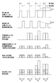
かかる問題点を、図16を参照して説明する。まず、図16に示す期間T11において、対象物体が検出対象空間に存在しない状態で、第1期間に供給する第1駆動電流値と、第2期間に供給する第2駆動電流値とを等しくして一部の点光源と他の一部の点光源と第1期間と第2期間で順次点灯させると、対象物体で反射した検出光(反射光)の強度はゼロであるが、備品等の対象物体以外の物体で反射した検出光が迷光として受光部に入射する。次に、期間T12において対象物体が検出対象空間に出現すると、受光部は、対象物体で反射した反射光と迷光とを受光する。ここで、受光部での受光強度が第1期間と第2期間とで等しい場合、対象物体が中心位置にあるとわかる。これに対して、期間T13のように、受光部での受光強度が第1期間と第2期間とで異なる場合、期間T14のように、受光部での受光強度が第1期間と第2期間とで等しくなるように、第1期間に供給する第1駆動電流値および第2期間に供給する第2駆動電流値を調整する。そして、受光部での受光強度が第1期間と第2期間とで等しくなったとき、第1駆動電流値に対する調整量ΔI11と第2駆動電流値に対する調整量ΔI12との差や比等を用いれば、対象物体の位置を検出できるはずである。   Such a problem will be described with reference to FIG. First, in a period T11 shown in FIG. 16, the first drive current value supplied in the first period is made equal to the second drive current value supplied in the second period in a state where the target object does not exist in the detection target space. If some point light sources and some other point light sources are turned on sequentially in the first period and the second period, the intensity of the detection light (reflected light) reflected by the target object is zero. Detection light reflected by an object other than the target object enters the light receiving unit as stray light. Next, when the target object appears in the detection target space in the period T12, the light receiving unit receives reflected light and stray light reflected by the target object. Here, when the received light intensity at the light receiving unit is the same in the first period and the second period, it can be understood that the target object is at the center position. On the other hand, when the received light intensity at the light receiving unit is different between the first period and the second period as in the period T13, the received light intensity at the light receiving unit is the first period and the second period as in the period T14. The first drive current value supplied in the first period and the second drive current value supplied in the second period are adjusted so as to be equal to each other. When the received light intensity at the light receiving unit becomes equal between the first period and the second period, the difference or ratio between the adjustment amount ΔI11 for the first drive current value and the adjustment amount ΔI12 for the second drive current value is used. For example, the position of the target object should be detectable.

しかしながら、受光部は、対象物体で反射した検出光を受光するとともに、検出光が対象物体以外の物体で反射した迷光も受光する。ここで、迷光の強度は、検出光の出射強度に比例するため、第1駆動電流値および第2駆動電流値を調整すると、迷光の強度も変動してしまう。その結果、期間T14に示すように、実際には第1期間と第2期間とにおいて対象物体で反射した検出光に対する受光強度が相違しているにもかかわらず、第1期間と第2期間とにおいて受光部での受光強度が等しくなってしまい、検出誤差が発生する。   However, the light receiving unit receives the detection light reflected by the target object and also receives the stray light reflected by the object other than the target object. Here, since the intensity of the stray light is proportional to the emission intensity of the detection light, adjusting the first drive current value and the second drive current value also changes the stray light intensity. As a result, as shown in the period T14, the first period and the second period are actually different in the light reception intensity with respect to the detection light reflected by the target object in the first period and the second period. , The received light intensity at the light receiving section becomes equal, and a detection error occurs.

以上の問題点に鑑みて、本発明の課題は、検出光が対象物体以外の物体で反射して受光部に入射することに起因する検出誤差の発生を防止することのできる位置検出装置、該位置検出装置を備えた入力機能付き表示システム、および位置検出方法を提供することにある。   In view of the above problems, an object of the present invention is to provide a position detection device that can prevent detection errors caused by detection light reflected off an object other than a target object and incident on a light receiving unit, An object is to provide a display system with an input function including a position detection device, and a position detection method.

上記課題を解決するために、本発明は、対象物体の位置を光学的に検出する位置検出装置であって、第1光強度分布を形成する第1検出光、および前記第1光強度分布と異なる第2光強度分布を形成する第2検出光を出射する検出用光源部と、前記第1光強度分布および前記第2光強度分布が形成された空間に位置する前記対象物体により反射してきた前記第1検出光および第2検出光の反射光を受光する受光部と、前記第1光強度分布および前記第2光強度分布が形成された空間を介さずに前記受光部に入射する補償光を出射する補償用光源部と、前記第1検出光および前記補償光を出射する第1期間において前記検出用光源部に供給する第1駆動電流値、前記第2検出光および前記補償光を出射する第2期間において前記検出用光源部に供給する第2駆動電流値、および前記補償用光源部に供給する第3駆動電流値の増減を行う光源駆動部と、前記第1期間における前記受光部の受光強度と前記第2期間における前記受光部での受光強度とが等しくなったときの前記第1駆動電流値および前記第2駆動電流値に基づいて前記対象物体の位置を検出する位置検出部と、を有し、前記光源駆動部は、前記第1駆動電流値を増大させるときには前記第3駆動電流値を低減し、前記第1駆動電流値を低減させるときには前記第3駆動電流値を増大させ、前記第2駆動電流値を増大させるときには前記第3駆動電流値を低減し、前記第2駆動電流値を低減させるときには前記第3駆動電流値を増大させることを特徴とする。   In order to solve the above problems, the present invention provides a position detection device that optically detects the position of a target object, the first detection light forming a first light intensity distribution, and the first light intensity distribution; Reflected by the detection light source unit that emits the second detection light that forms a different second light intensity distribution, and the target object that is located in the space in which the first light intensity distribution and the second light intensity distribution are formed A light receiving unit that receives reflected light of the first detection light and the second detection light, and compensation light that is incident on the light receiving unit without passing through the space in which the first light intensity distribution and the second light intensity distribution are formed. And a first driving current value, second detection light, and compensation light that are supplied to the detection light source in a first period of emitting the first detection light and the compensation light. In the second period, the detection light source unit A light source driving unit that increases or decreases a second driving current value to be supplied and a third driving current value to be supplied to the compensation light source unit, and a light receiving intensity of the light receiving unit in the first period and the light receiving in the second period. A position detection unit that detects the position of the target object based on the first drive current value and the second drive current value when the received light intensity at the unit becomes equal, the light source drive unit When the first drive current value is increased, the third drive current value is decreased. When the first drive current value is decreased, the third drive current value is increased, and the second drive current value is increased. The third drive current value is sometimes reduced, and when the second drive current value is reduced, the third drive current value is increased.

本発明では、第1期間において、検出用光源部を第1駆動電流値で駆動して第1光強度分布を形成した第1期間における受光部の受光強度と、検出用光源部を第2駆動電流値で駆動して第2光強度分布を形成した第2期間における受光部の受光強度とが等しくなった時点での第1駆動電流値および第2駆動電流値に基づいて対象物体の位置を検出する。かかる位置検出の際、受光部は、対象物体で反射した検出光を受光するとともに、検出光が備品等で反射した検出光(迷光)も受光する。ここで、迷光の強度は、光源からの出射強度に比例するため、第1駆動電流値および第2駆動電流値を調整すると、迷光の強度も変動してしまうが、本発明では、第1光強度分布および第2光強度分布が形成された空間を介さずに受光部に入射する補償光を出射する補償用光源部を設け、第1駆動電流値を増大させるときには、補償用光源部に供給する第3駆動電流値を低減し、第1駆動電流値を低減させるときには第3駆動電流値を増大させる。また、第2駆動電流値を増大させるときには第3駆動電流値を低減し、第2駆動電流値を低減させるときには第3駆動電流値を増大させる。従って、第1駆動電流値および第2駆動電流値を調整した際の迷光の受光強度の強度変化を補償光の受光強度の強度変化で補正することができる。従って、検出光が対象物体以外の物体で反射して受光部に入射することに起因する検出誤差の発生を防止することができる。   In the present invention, in the first period, the detection light source unit is driven with the first drive current value to form the first light intensity distribution, and the light reception intensity of the light reception unit in the first period and the detection light source unit are driven second. The position of the target object is determined based on the first drive current value and the second drive current value at the time when the received light intensity of the light receiving unit in the second period in which the second light intensity distribution is formed by driving with the current value becomes equal. To detect. At the time of such position detection, the light receiving unit receives the detection light reflected by the target object and also receives the detection light (stray light) reflected by the fixture or the like. Here, since the intensity of stray light is proportional to the intensity of light emitted from the light source, adjusting the first drive current value and the second drive current value also changes the intensity of the stray light. A compensation light source unit that emits compensation light incident on the light receiving unit without passing through the space in which the intensity distribution and the second light intensity distribution are formed is provided, and supplied to the compensation light source unit when the first drive current value is increased. The third drive current value is decreased, and when the first drive current value is reduced, the third drive current value is increased. Further, when the second drive current value is increased, the third drive current value is decreased, and when the second drive current value is decreased, the third drive current value is increased. Accordingly, the intensity change of the received light intensity of the stray light when the first drive current value and the second drive current value are adjusted can be corrected by the intensity change of the received light intensity of the compensation light. Accordingly, it is possible to prevent occurrence of a detection error due to the detection light being reflected by an object other than the target object and entering the light receiving unit.

本発明において、前記光源駆動部は、前記第1駆動電流値と前記第2駆動電流値とを初期電流値に設定して前記第1検出光および前記第2検出光を出射させた後、前記受光部での受光結果に基づいて前記第1駆動電流値および前記第2駆動電流値の増減を行い、前記位置検出部は、前記第1期間における前記受光部の受光強度と前記第2期間における前記受光部での受光強度とが等しくなったときの前記第1駆動電流値と前記初期電流値との差、および前記第2駆動電流値と前記初期電流値との差に基づいて前記対象物体の位置を検出する構成を採用することができる。かかる構成によれば、外光等の環境光の影響を防止することができる。   In the present invention, the light source driving unit sets the first driving current value and the second driving current value to an initial current value and emits the first detection light and the second detection light, and then The first drive current value and the second drive current value are increased / decreased based on a light reception result at the light receiving unit, and the position detection unit is configured to detect the light reception intensity of the light receiving unit in the first period and the second period. The target object based on the difference between the first drive current value and the initial current value when the received light intensity at the light receiving unit becomes equal, and the difference between the second drive current value and the initial current value It is possible to adopt a configuration for detecting the position of. According to this configuration, it is possible to prevent the influence of ambient light such as outside light.

本発明において、前記検出用光源部は、前記第1検出光を出射する第1検出用光源と、前記第2検出光を出射する第2検出用光源と、を備えていることが好ましい。   In the present invention, it is preferable that the detection light source unit includes a first detection light source that emits the first detection light and a second detection light source that emits the second detection light.

この場合、前記光源駆動部は、前記第1検出用光源および前記第2検出用光源を電圧振幅変調により駆動し、前記第1期間において、定電圧と前記第1検出用光源に供給される駆動電圧との差に相当する電圧が前記補償用光源部に印加され、前記第2期間において、定電圧と前記第2検出用光源に供給される駆動電圧との差に相当する電圧が前記補償用光源部に印加される構成を採用することができる。   In this case, the light source driving unit drives the first detection light source and the second detection light source by voltage amplitude modulation, and is supplied to the constant voltage and the first detection light source in the first period. A voltage corresponding to a difference from a voltage is applied to the compensation light source unit, and a voltage corresponding to a difference between a constant voltage and a driving voltage supplied to the second detection light source is applied to the compensation light source in the second period. A configuration applied to the light source unit can be employed.

また、本発明においては、前記光源駆動部は、前記第1検出用光源および前記第2検出用光源をパルス幅変調により駆動し、前記第1期間には前記第1検出用光源に供給する駆動パルスに対して相補関係にある駆動パルスを前記補償用光源部に供給し、前記第2期間には前記第2検出用光源に供給する駆動パルスに対して相補関係にある駆動パルスを前記補償用光源部に供給する構成を採用してもよい。   In the present invention, the light source driving unit drives the first detection light source and the second detection light source by pulse width modulation, and supplies the first detection light source to the first detection light source in the first period. A drive pulse complementary to the pulse is supplied to the compensation light source unit, and a drive pulse complementary to the drive pulse supplied to the second detection light source is supplied to the compensation in the second period. You may employ | adopt the structure supplied to a light source part.

本発明において、前記第1光強度分布および前記第2光強度分布が形成された空間に前記対象物体が存在しない状態において、前記第1駆動電流値を初期電流値に設定して前記検出用光源部を駆動した際の前記受光部での受光強度と、前記第1駆動電流値を当該初期電流値から増減させて前記検出用光源部を駆動した際の前記受光部での受光強度と、が等しく、前記第2駆動電流値を初期電流値に設定して前記検出用光源部を駆動した際の前記受光部での受光強度と、前記第2駆動電流値を当該初期電流値から増減させて前記検出用光源部を駆動した際の前記受光部での受光強度と、が等しいことが好ましい。   In the present invention, in the state where the target object does not exist in the space where the first light intensity distribution and the second light intensity distribution are formed, the first drive current value is set to an initial current value, and the detection light source The received light intensity at the light receiving unit when the light source unit is driven, and the received light intensity at the light receiving unit when the light source unit for detection is driven by increasing or decreasing the first drive current value from the initial current value. Equally, by setting the second driving current value to the initial current value and driving the detection light source unit, the light receiving intensity at the light receiving unit and the second driving current value are increased or decreased from the initial current value. It is preferable that the received light intensity in the light receiving unit when the detection light source unit is driven is equal.

かかる構成は、前記第1光強度分布および前記第2光強度分布が形成された空間に前記対象物体が存在しない状態において、前記受光部での前記第1検出光の受光強度と前記受光部での前記補償光の受光強度との和は、前記受光部での前記第2検出光の受光強度と前記受光部での前記補償光の受光強度との和に等しい構成を採用することにより実現することができる。   With this configuration, in the state where the target object does not exist in the space where the first light intensity distribution and the second light intensity distribution are formed, the light receiving intensity of the first detection light in the light receiving unit and the light receiving unit Is obtained by adopting a configuration equal to the sum of the received light intensity of the second detection light at the light receiving unit and the received light intensity of the compensation light at the light receiving unit. be able to.

本発明に係る位置検出装置は、入力機能付き表示システム等、各種のシステムに利用することができる。例えば、本発明を適用した位置検出装置を備えた入力機能付き表示システムとしては、画像が表示される表示面を備えた表示装置を備え、前記位置検出装置での前記対象物体の位置検出結果に基づいて前記表示装置において前記表示面に表示される画像が切り換えられる入力機能付き表示システムを例示することができる。また、本発明を適用した位置検出装置を備えた入力機能付き表示システムとしては、画像を投射する画像投射装置を備え、前記位置検出装置での前記対象物体の位置検出結果に基づいて前記画像投射装置から投射される画像が切り換えられる入力機能付き表示システムを例示することができる。   The position detection apparatus according to the present invention can be used in various systems such as a display system with an input function. For example, as a display system with an input function including a position detection device to which the present invention is applied, a display device including a display surface on which an image is displayed is provided, and the position detection result of the target object is detected by the position detection device. Based on this, it is possible to exemplify a display system with an input function in which an image displayed on the display surface in the display device is switched. In addition, the display system with an input function including the position detection device to which the present invention is applied includes an image projection device that projects an image, and the image projection is performed based on the position detection result of the target object in the position detection device. A display system with an input function in which an image projected from the apparatus can be switched can be exemplified.

また、本発明は、対象物体の位置を光学的に検出する位置検出方法であって、第1期間に検出用光源部から第1検出光を出射させて第1光強度分布を形成するとともに補償用光源部から前記第1光強度分布が形成された空間を介さずに受光部に入射する補償光を出射する第1光出射工程と、第2期間に前記検出用光源部から第2検出光を出射させて第2光強度分布を形成するとともに前記補償用光源部から前記補償光を出射する第2光出射工程と、前記第1期間に前記検出用光源部に供給する第1駆動電流値、前記第2期間に前記検出用光源部に供給する第2駆動電流値、および前記補償用光源部に供給する第3駆動電流値の増減を行う電流増減工程と、前記第1期間における前記受光部の受光強度と前記第2期間における前記受光部での受光強度とが等しくなったときの前記第1駆動電流値および前記第2駆動電流値に基づいて前記第1光強度分布および前記第2光強度分布が形成された空間に位置する前記対象物体の位置を検出する位置検出工程と、を有し、前記電流増減工程では、前記第1駆動電流値を増大させるときには前記第3駆動電流値を低減し、前記第1駆動電流値を低減させるときには前記第3駆動電流値を増大させ、前記第2駆動電流値を増大させるときには前記第3駆動電流値を低減し、前記第2駆動電流値を低減させるときには前記第3駆動電流値を増大させることを特徴とする。   Further, the present invention is a position detection method for optically detecting the position of a target object, wherein the first light intensity distribution is formed by emitting the first detection light from the light source unit for detection in the first period and is compensated. A first light emitting step of emitting compensation light incident on the light receiving unit without passing through the space in which the first light intensity distribution is formed from the light source unit for use, and second detection light from the light source unit for detection in the second period Is emitted to form a second light intensity distribution and the compensation light is emitted from the compensation light source unit, and a first drive current value supplied to the detection light source unit in the first period A current increase / decrease step for increasing / decreasing a second drive current value supplied to the detection light source unit in the second period and a third drive current value supplied to the compensation light source unit; and the light reception in the first period Received light intensity at the light receiving portion and light receiving at the light receiving portion during the second period. The position of the target object located in the space where the first light intensity distribution and the second light intensity distribution are formed based on the first drive current value and the second drive current value when the intensity becomes equal In the current increase / decrease step, the third drive current value is reduced when the first drive current value is increased, and the first drive current value is reduced when the first drive current value is reduced. The third drive current value is increased, the third drive current value is decreased when the second drive current value is increased, and the third drive current value is increased when the second drive current value is decreased. And

本発明では、第1期間において、検出用光源部を第1駆動電流値で駆動して第1光強度分布を形成した第1期間における受光部の受光強度と、検出用光源部を第2駆動電流値で駆動して第2光強度分布を形成した第2期間における受光部の受光強度とが等しくなった時点での第1駆動電流値および第2駆動電流値に基づいて対象物体の位置を検出する。かかる位置検出の際、受光部は、対象物体で反射した検出光を受光するとともに、検出光が備品等で反射した検出光(迷光)も受光する。ここで、迷光の強度は、光源からの出射強度に比例するため、第1駆動電流値および第2駆動電流値を調整すると、迷光の強度も変動してしまうが、本発明では、第1光強度分布および第2光強度分布が形成された空間を介さずに受光部に入射する補償光を出射する補償用光源部を設け、第1駆動電流値を増大させるときには、補償用光源部に供給する第3駆動電流値を低減し、第1駆動電流値を低減させるときには第3駆動電流値を増大させる。また、第2駆動電流値を増大させるときには第3駆動電流値を低減し、第2駆動電流値を低減させるときには第3駆動電流値を増大させる。従って、第1駆動電流値および第2駆動電流値を調整した際の迷光の受光強度の強度変化を補償光の受光強度の強度変化で補正することができる。従って、検出光が対象物体以外の物体で反射して受光部に入射することに起因する検出誤差の発生を防止することができる。   In the present invention, in the first period, the detection light source unit is driven with the first drive current value to form the first light intensity distribution, and the light reception intensity of the light reception unit in the first period and the detection light source unit are driven second. The position of the target object is determined based on the first drive current value and the second drive current value at the time when the received light intensity of the light receiving unit in the second period in which the second light intensity distribution is formed by driving with the current value becomes equal. To detect. At the time of such position detection, the light receiving unit receives the detection light reflected by the target object and also receives the detection light (stray light) reflected by the fixture or the like. Here, since the intensity of stray light is proportional to the intensity of light emitted from the light source, adjusting the first drive current value and the second drive current value also changes the intensity of the stray light. A compensation light source unit that emits compensation light incident on the light receiving unit without passing through the space in which the intensity distribution and the second light intensity distribution are formed is provided, and supplied to the compensation light source unit when the first drive current value is increased. The third drive current value is decreased, and when the first drive current value is reduced, the third drive current value is increased. Further, when the second drive current value is increased, the third drive current value is decreased, and when the second drive current value is decreased, the third drive current value is increased. Accordingly, the intensity change of the received light intensity of the stray light when the first drive current value and the second drive current value are adjusted can be corrected by the intensity change of the received light intensity of the compensation light. Accordingly, it is possible to prevent occurrence of a detection error due to the detection light being reflected by an object other than the target object and entering the light receiving unit.

本発明の実施の形態1に係る位置検出装置の主要部を模式的に示す説明図である。It is explanatory drawing which shows typically the principal part of the position detection apparatus which concerns on Embodiment 1 of this invention. 本発明の実施の形態1に係る位置検出装置の受発光ユニットの説明図である。It is explanatory drawing of the light emitting / receiving unit of the position detection apparatus which concerns on Embodiment 1 of this invention. 図2に示す受発光ユニットの主要部の構成を示す説明図である。It is explanatory drawing which shows the structure of the principal part of the light emitting / receiving unit shown in FIG. 図3に示す受発光ユニットに構成した光源部の構成を模式的に示す説明図である。It is explanatory drawing which shows typically the structure of the light source part comprised in the light emitting / receiving unit shown in FIG. 本発明の実施の形態1に係る位置検出装置の電気的構成等を示す説明図である。It is explanatory drawing which shows the electrical structure etc. of the position detection apparatus which concerns on Embodiment 1 of this invention. 本発明の実施の形態1に係る位置検出装置における位置検出原理を示す説明図である。It is explanatory drawing which shows the position detection principle in the position detection apparatus which concerns on Embodiment 1 of this invention. 本発明の実施の形態1に係る位置検出装置において対象物体のXY座標データを取得する原理を示す説明図である。It is explanatory drawing which shows the principle which acquires the XY coordinate data of a target object in the position detection apparatus which concerns on Embodiment 1 of this invention. 本発明の実施の形態1に係る位置検出装置の光源駆動部に設けた光源回路の説明図である。It is explanatory drawing of the light source circuit provided in the light source drive part of the position detection apparatus which concerns on Embodiment 1 of this invention. 本発明の実施の形態1に係る位置検出装置における迷光補償の原理を示す説明図である。It is explanatory drawing which shows the principle of the stray light compensation in the position detection apparatus which concerns on Embodiment 1 of this invention. 本発明の実施の形態2に係る位置検出装置の光源駆動部に設けた光源回路の説明図である。It is explanatory drawing of the light source circuit provided in the light source drive part of the position detection apparatus which concerns on Embodiment 2 of this invention. 本発明の実施の形態3に係る位置検出装置の受発光ユニットの説明図である。It is explanatory drawing of the light emitting / receiving unit of the position detection apparatus which concerns on Embodiment 3 of this invention. 図11に示す受発光ユニットにおける光源部の説明図である。It is explanatory drawing of the light source part in the light emitting / receiving unit shown in FIG. 本発明の実施の形態3に係る位置検出装置の電気的構成等を示す説明図である。It is explanatory drawing which shows the electrical structure etc. of the position detection apparatus which concerns on Embodiment 3 of this invention. 本発明を適用した位置検出システムの具体例1(入力機能付き表示システム)の説明図である。It is explanatory drawing of the specific example 1 (display system with an input function) of the position detection system to which this invention is applied. 本発明を適用した位置検出システムの具体例2(入力機能付き表示システム/入力機能付き投射型表示システム)の説明図である。It is explanatory drawing of the specific example 2 (display system with an input function / projection type display system with an input function) of the position detection system to which this invention is applied. 従来の位置検出装置の問題を示す説明図である。It is explanatory drawing which shows the problem of the conventional position detection apparatus.

次に、添付図面を参照して本発明の実施形態について詳細に説明する。なお、以下の説明においては、互いに交差する方向をX軸方向およびY軸方向とし、X軸方向およびY軸方向に交差する方向をZ軸方向とする。また、以下に参照する図面では、X軸方向の一方側をX1側とし、他方側をX2側とし、Y軸方向の一方側をY1側とし、他方側をY2側とし、Z軸方向の一方側をZ1側とし、他方側をZ2側として表してある。   Next, embodiments of the present invention will be described in detail with reference to the accompanying drawings. In the following description, directions intersecting each other are defined as an X-axis direction and a Y-axis direction, and directions intersecting the X-axis direction and the Y-axis direction are defined as a Z-axis direction. In the drawings referred to below, one side in the X-axis direction is the X1 side, the other side is the X2 side, one side in the Y-axis direction is the Y1 side, the other side is the Y2 side, and one side in the Z-axis direction The side is represented as the Z1 side, and the other side is represented as the Z2 side.

[実施の形態1]
(全体構成)
図1は、本発明の実施の形態1に係る位置検出装置の主要部を模式的に示す説明図であり、図1(a)、(b)は、位置検出装置を検出光出射空間側の斜め方向からみたときの説明図、および位置検出装置を正面からみたときの説明図である。
[Embodiment 1]
(overall structure)
FIG. 1 is an explanatory diagram schematically showing the main part of a position detection device according to Embodiment 1 of the present invention. FIGS. 1 (a) and 1 (b) show the position detection device on the detection light emission space side. It is explanatory drawing when it sees from the diagonal direction, and explanatory drawing when a position detection apparatus is seen from the front.

図1において、本形態の位置検出システム1は、対象物体Obの位置を検出する位置検出装置10を有しており、かかる位置検出装置10は、X軸方向およびY軸方向により規定される仮想のXY平面(仮想面)に沿うように放射状に出射した検出光L2を利用して、対象物体Obの位置を検出する。本形態において、位置検出システム1は、XY平面に沿って広がる視認面41をZ軸方向の一方側Z1に備えた視認面構成部材40を有しており、位置検出装置10は、視認面41に沿って検出光L2を出射し、視認面構成部材40に対して視認面41側(Z軸方向の一方側Z1)に位置する対象物体Obの位置を検出する。従って、位置検出システム1の検出対象空間10Rは、位置検出装置10において検出光L2が出射される検出光出射空間であり、検出対象空間10Rには、後述する検出光L2の光強度分布が形成される。かかる位置検出システム1は、位置検出装置10によって、後述する電子黒板等の入力機能付き表示システムや入力機能付き投射型表示システム等として用いることができる。   In FIG. 1, the position detection system 1 of the present embodiment includes a position detection device 10 that detects the position of the target object Ob. The position detection device 10 is a virtual that is defined by the X-axis direction and the Y-axis direction. The position of the target object Ob is detected using the detection light L2 emitted radially along the XY plane (virtual plane). In the present embodiment, the position detection system 1 includes a viewing surface constituent member 40 provided with a viewing surface 41 that extends along the XY plane on one side Z1 in the Z-axis direction, and the position detection device 10 includes the viewing surface 41. The detection light L <b> 2 is emitted along and the position of the target object Ob located on the viewing surface 41 side (one side Z <b> 1 in the Z-axis direction) with respect to the viewing surface constituent member 40 is detected. Accordingly, the detection target space 10R of the position detection system 1 is a detection light emission space from which the detection light L2 is emitted in the position detection device 10, and a light intensity distribution of the detection light L2 described later is formed in the detection target space 10R. Is done. The position detection system 1 can be used as a display system with an input function such as an electronic blackboard, which will be described later, or a projection display system with an input function, by the position detection device 10.

本形態の位置検出システム1において、位置検出装置10は、視認面41(XY平面)に沿って検出光L2を放射状に出射する検出用光源部12(線状光源部)と、検出光L2の出射空間(検出対象空間10R)に位置する対象物体Obで反射した検出光L2(反射光L3)を受光する受光部13とを備えている。   In the position detection system 1 of the present embodiment, the position detection device 10 includes a detection light source unit 12 (linear light source unit) that radiates detection light L2 radially along the viewing surface 41 (XY plane), and the detection light L2. And a light receiving unit 13 that receives the detection light L2 (reflected light L3) reflected by the target object Ob located in the emission space (detection target space 10R).

本形態においては、検出用光源部12として、視認面構成部材40に対してY軸方向の一方側Y1に離間する位置で検出対象空間10Rに向く2つの検出用光源部12(第1検出用光源部12Aおよび第2検出用光源部12B)が用いられており、第1検出用光源部12Aと第2検出用光源部12Bとは、X軸方向で離間し、Y軸方向では同一の位置にある。また、本形態においては、受光部13として、視認面構成部材40に対してY軸方向の一方側Y1に離間する位置で検出対象空間10Rに向く第1受光部13Aおよび第2受光部13Bが用いられており、第1受光部13Aと第2受光部13Bとは、X軸方向で離間し、Y軸方向では同一の位置にある。   In this embodiment, as the detection light source unit 12, two detection light source units 12 (first detection use) that face the detection target space 10R at positions separated from the viewing surface constituent member 40 on one side Y1 in the Y-axis direction. The first light source unit 12A and the second light source unit 12B are spaced apart in the X-axis direction and the same position in the Y-axis direction. It is in. Further, in the present embodiment, as the light receiving unit 13, the first light receiving unit 13A and the second light receiving unit 13B facing the detection target space 10R at positions separated from the viewing surface constituent member 40 on the one side Y1 in the Y axis direction. The first light receiving unit 13A and the second light receiving unit 13B are separated in the X-axis direction and are in the same position in the Y-axis direction.

ここで、第1受光部13Aは、第1検出用光源部12Aから放射状に出射される検出光L2(検出光L2a)の放射中心位置に配置されており、第1受光部13Aと第1検出用光源部12Aとは第1受発光ユニット15Aとして一体化されている。また、第2受光部13Bは、第2検出用光源部12Bから放射状に出射される検出光L2(検出光L2b)の放射中心位置に配置されており、第2受光部13Bと第2検出用光源部12Bとは第2受発光ユニット15Bとして一体化されている。   Here, the first light receiving unit 13A is disposed at the radiation center position of the detection light L2 (detection light L2a) emitted radially from the first light source unit 12A for detection, and the first light receiving unit 13A and the first detection unit 13A. The light source unit 12A is integrated as a first light emitting / receiving unit 15A. In addition, the second light receiving unit 13B is disposed at the radiation center position of the detection light L2 (detection light L2b) emitted radially from the second light source unit 12B for detection, and is connected to the second light receiving unit 13B and the second detection light. The light source unit 12B is integrated as a second light emitting / receiving unit 15B.

後述するように、2つの検出用光源部12(第1検出用光源部12Aおよび第2検出用光源部12B)は各々、LED(発光ダイオード)等の発光素子からなる検出用光源(点光源)を備えており、かかる検出用光源は、ピーク波長が840〜1000nmに位置する赤外光からなる検出光L2(検出光L2a、L2b)を発散光として出射する。受光部13(第1受光部13Aおよび第2受光部13B)は各々、フォトダイオードやフォトトランジスター等の受光素子130を備えており、本形態において、受光素子130は赤外域に感度ピークを備えたフォトダイオードである。   As will be described later, each of the two detection light source units 12 (the first detection light source unit 12A and the second detection light source unit 12B) is a detection light source (point light source) composed of a light emitting element such as an LED (light emitting diode). The detection light source emits detection light L2 (detection light L2a, L2b) made of infrared light having a peak wavelength of 840 to 1000 nm as diverging light. Each of the light receiving sections 13 (first light receiving section 13A and second light receiving section 13B) includes a light receiving element 130 such as a photodiode or a phototransistor. In this embodiment, the light receiving element 130 has a sensitivity peak in the infrared region. It is a photodiode.

第1受発光ユニット15Aおよび第2受発光ユニット15Bは、視認面構成部材40よりZ軸方向の一方側Z1に突出した位置にある。また、第1受発光ユニット15Aと第2受発光ユニット15Bとは異なる期間において動作する。従って、第1受発光ユニット15Aにおいて、第1検出用光源部12Aから検出光L2aが出射された際、第1受光部13Aは、検出対象空間10Rに位置する対象物体Obで反射した検出光L2a(反射光L3)を受光する。かかる動作とは異なる期間において、第2受発光ユニット15Bにおいて、第2検出用光源部12Bから検出光L2bが出射された際、第2受光部13Bは、検出対象空間10Rに位置する対象物体Obで反射した検出光L2b(反射光L3)を受光する。   The first light emitting / receiving unit 15A and the second light emitting / receiving unit 15B are located at positions projecting from the viewing surface constituting member 40 to one side Z1 in the Z-axis direction. The first light emitting / receiving unit 15A and the second light emitting / receiving unit 15B operate in different periods. Therefore, in the first light receiving / emitting unit 15A, when the detection light L2a is emitted from the first light source unit 12A, the first light receiving unit 13A detects the detection light L2a reflected by the target object Ob located in the detection target space 10R. (Reflected light L3) is received. When the detection light L2b is emitted from the second detection light source unit 12B in the second light emitting / receiving unit 15B in a period different from the operation, the second light receiving unit 13B is configured to detect the target object Ob located in the detection target space 10R. The detection light L2b (reflected light L3) reflected by is received.

本形態の位置検出装置10において、検出用光源部12(第1検出用光源部12Aおよび第2検出用光源部12B)から検出光L2が出射された際、備品等の対象物体以外の物体Sbで反射した検出光が迷光L5として受光部13(第1受光部13Aおよび第2受光部13B)に入射する。そこで、詳しくは後述するように、第1受発光ユニット15Aおよび第2受発光ユニット15Bには、補償用光源部14(第1補償用光源部14Aおよび第2補償用光源部14B)が設けられている。   In the position detection device 10 of the present embodiment, when the detection light L2 is emitted from the detection light source unit 12 (the first detection light source unit 12A and the second detection light source unit 12B), the object Sb other than the target object such as fixtures The detection light reflected by the light enters the light receiving unit 13 (the first light receiving unit 13A and the second light receiving unit 13B) as stray light L5. Therefore, as will be described in detail later, the first light receiving / emitting unit 15A and the second light receiving / emitting unit 15B are provided with a compensation light source unit 14 (first compensation light source unit 14A and second compensation light source unit 14B). ing.

(検出用光源部12の具体的構成)
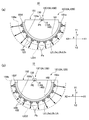
図2は、本発明の実施の形態1に係る位置検出装置10の受発光ユニットの説明図である。図3は、図2に示す受発光ユニットの主要部の構成を示す説明図である。図4は、図3に示す受発光ユニットに構成した検出用光源部12の構成を模式的に示す説明図であり、第1期間の第1点灯動作時に検出光L2(第1検出光L2s)が出射される様子を示す説明図、および第2期間の第2点灯動作時に検出光L2(第2検出光L2t)が出射される様子を示す説明図である。
(Specific Configuration of Detection Light Source 12)
FIG. 2 is an explanatory diagram of the light emitting / receiving unit of the position detection device 10 according to the first embodiment of the present invention. FIG. 3 is an explanatory diagram showing a configuration of a main part of the light emitting / receiving unit shown in FIG. FIG. 4 is an explanatory diagram schematically showing the configuration of the light source unit for detection 12 configured in the light receiving and emitting unit shown in FIG. 3, and the detection light L2 (first detection light L2s) during the first lighting operation in the first period. It is explanatory drawing which shows a mode that light is emitted, and explanatory drawing which shows a mode that detection light L2 (2nd detection light L2t) is radiate | emitted at the time of the 2nd lighting operation of a 2nd period.

図2に示すように、本形態の位置検出装置10において、第1受発光ユニット15Aおよび第2受発光ユニット15Bは同一の構成を有しており、それ故、第1検出用光源部12Aおよび第2検出用光源部12Bも同一の構成を有している。より具体的には、第1受発光ユニット15Aは、Z軸方向からみたときに扇形形状あるいは半円形状を有する光源支持部材150を有している。かかる光源支持部材150は、第1光源支持部材151と第2光源支持部材152とがZ軸方向で重ねられた構造になっており、第1光源支持部材151および第2光源支持部材152は各々、扇形形状あるいは半円形状の鍔部156a、156bを備えている。鍔部156a、156bにより挟まれた部分は、第1検出用光源部12Aから検出光L2が出射される出射部になっており、鍔部156a、156bは、Z軸方向における検出光L2の出射範囲を制限している。   As shown in FIG. 2, in the position detection device 10 of the present embodiment, the first light receiving / emitting unit 15A and the second light receiving / emitting unit 15B have the same configuration, and therefore the first detection light source unit 12A and The second light source unit 12B for detection also has the same configuration. More specifically, the first light emitting / receiving unit 15A includes a light source support member 150 having a fan shape or a semicircular shape when viewed from the Z-axis direction. The light source support member 150 has a structure in which a first light source support member 151 and a second light source support member 152 are stacked in the Z-axis direction, and each of the first light source support member 151 and the second light source support member 152 has a structure. The fan-shaped or semi-circular flanges 156a and 156b are provided. The portion sandwiched between the flange portions 156a and 156b is an emission portion from which the detection light L2 is emitted from the first detection light source portion 12A, and the flange portions 156a and 156b emit the detection light L2 in the Z-axis direction. The range is limited.

第1受発光ユニット15Aにおいて、第1検出用光源部12Aは、検出光L2の出射部として、Z軸方向に重ねて配置された第1光源モジュール126と第2光源モジュール127とを備えている。第1検出用光源部12Aにおいて、第1光源モジュール126と第2光源モジュール127とによってZ軸方向で挟まれた部分は透光性の導光部128になっており、かかる導光部128の奥に第1受光部13Aの受光素子130が配置されている。第2受発光ユニット15Bも、第1受発光ユニット15Aと同様な構成を有しているため、説明を省略する。   In the first light receiving and emitting unit 15A, the first light source unit 12A for detection includes a first light source module 126 and a second light source module 127 that are arranged to overlap in the Z-axis direction as the output part of the detection light L2. . In the first detection light source unit 12A, a portion sandwiched between the first light source module 126 and the second light source module 127 in the Z-axis direction is a light-transmitting light guide unit 128. The light receiving element 130 of the first light receiving unit 13A is disposed in the back. Since the second light emitting / receiving unit 15B also has the same configuration as the first light emitting / receiving unit 15A, description thereof is omitted.

図3に示すように、第1受発光ユニット15Aにおいて、第1光源モジュール126および第2光源モジュール127はいずれも、発光ダイオード等の発光素子からなる検出用光源120、および円弧状のライトガイドLGを備えている。第2受発光ユニット15Bにおいても、第1受発光ユニット15Aと同様、第1光源モジュール126および第2光源モジュール127はいずれも、発光ダイオード等の発光素子からなる検出用光源120、および円弧状のライトガイドLGを備えている。   As shown in FIG. 3, in the first light receiving / emitting unit 15A, each of the first light source module 126 and the second light source module 127 includes a light source for detection 120 including a light emitting element such as a light emitting diode, and an arc-shaped light guide LG. It has. In the second light receiving / emitting unit 15B, as in the first light receiving / emitting unit 15A, each of the first light source module 126 and the second light source module 127 includes a detection light source 120 including a light emitting element such as a light emitting diode, and an arc-shaped light source. A light guide LG is provided.

図4に示すように、第1光源モジュール126は、検出用光源120として、赤外光を出射する発光ダイオード等の発光素子からなる第1検出用光源121を備えているとともに、円弧状のライトガイドLGを備えており、第1検出用光源121は、ライトガイドLGの一方の端部LG1に配置されている。また、第1光源モジュール126は、ライトガイドLGの円弧状の外周面LG3に沿って、光学シートPSおよびルーバーフィルムLF等を備えた円弧状の照射方向設定部LEを備え、ライトガイドLGの円弧状の内周面LG4に沿って、円弧状の反射シートRSを備えている。第2光源モジュール127も、第1光源モジュール126と同様、検出用光源120として、赤外光を出射する発光ダイオード等の発光素子からなる第2検出用光源122を備えているとともに、円弧状のライトガイドLGを備えており、第2検出用光源122は、ライトガイドLGの他方の端部LG2に配置されている。また、第2光源モジュール127も、第1光源モジュール126と同様、ライトガイドLGの円弧状の外周面LG3に沿って、光学シートPSおよびルーバーフィルムLF等を備えた円弧状の照射方向設定部LEを備え、ライトガイドLGの円弧状の内周面LG4に沿って、円弧状の反射シートRSを備えている。なお、ライトガイドLGの外周面LG3および内周面LG4のうちの少なくとも一方には、ライトガイドLGからの検出光L2の出射効率を調整するための加工が施されており、かかる加工手法としては、例えば反射ドットを印刷する方式や、スタンパーやインジェクションにより凹凸を付す成型方式や、溝加工方式を採用することができる。第2受発光ユニット15Bも、第1受発光ユニット15Aと同様な構成を有しているため、説明を省略する。   As shown in FIG. 4, the first light source module 126 includes a first light source for detection 121 made of a light emitting element such as a light emitting diode that emits infrared light as the light source for detection 120, and an arc-shaped light. A guide LG is provided, and the first detection light source 121 is disposed at one end LG1 of the light guide LG. The first light source module 126 includes an arc-shaped irradiation direction setting unit LE including the optical sheet PS, the louver film LF, and the like along the arc-shaped outer peripheral surface LG3 of the light guide LG. An arcuate reflecting sheet RS is provided along the arcuate inner circumferential surface LG4. Similarly to the first light source module 126, the second light source module 127 includes a second light source for detection 122 made of a light emitting element such as a light emitting diode that emits infrared light as the light source for detection 120. The light guide LG is provided, and the second light source for detection 122 is disposed at the other end LG2 of the light guide LG. Similarly to the first light source module 126, the second light source module 127 also has an arcuate irradiation direction setting unit LE provided with an optical sheet PS, a louver film LF, and the like along the arcuate outer circumferential surface LG3 of the light guide LG. And an arcuate reflection sheet RS is provided along the arcuate inner circumferential surface LG4 of the light guide LG. Note that at least one of the outer peripheral surface LG3 and the inner peripheral surface LG4 of the light guide LG is subjected to processing for adjusting the emission efficiency of the detection light L2 from the light guide LG. For example, it is possible to employ a method of printing reflective dots, a molding method of attaching irregularities by a stamper or injection, or a groove processing method. Since the second light emitting / receiving unit 15B also has the same configuration as the first light emitting / receiving unit 15A, description thereof is omitted.

(補償用光源部14の構成)
このように構成した位置検出装置10において、第1受発光ユニット15Aおよび第2受発光ユニット15Bは各々、補償用光源部14として、第1補償用光源部14Aおよび第2補償用光源部14Bを備えている。補償用光源部14は、例えば、受光部13に対してY軸方向の他方側Y2で一方側Y1に出射光軸を向けた発光ダイオード等の点光源からなり、補償用光源部14から出射された補償光L4は、検出対象空間10Rを介さずに、受光部13に入射する。
(Configuration of compensation light source unit 14)
In the position detecting device 10 configured as described above, the first light receiving / emitting unit 15A and the second light receiving / emitting unit 15B each include the first compensating light source unit 14A and the second compensating light source unit 14B as the compensating light source unit 14, respectively. I have. The compensation light source unit 14 includes, for example, a point light source such as a light-emitting diode having an emission optical axis directed to the other side Y2 in the Y-axis direction and the one side Y1 with respect to the light receiving unit 13, and is emitted from the compensation light source unit 14. The compensation light L4 enters the light receiving unit 13 without passing through the detection target space 10R.

(位置検出部等の構成)
図5は、本発明の実施の形態1に係る位置検出装置10の電気的構成等を示す説明図であり、図5(a)、(b)は、制御用ICの構成を示す説明図、および光源に供給される駆動信号の説明図である。
(Configuration of position detector, etc.)
FIG. 5 is an explanatory diagram illustrating an electrical configuration and the like of the position detection device 10 according to the first embodiment of the present invention, and FIGS. 5A and 5B are explanatory diagrams illustrating a configuration of a control IC. It is explanatory drawing of the drive signal supplied to a light source.

本形態の位置検出システム1に用いた位置検出装置10において、図1〜図4等を参照して説明した第1受発光ユニット15Aおよび第2受発光ユニット15Bは、図5(a)に示す制御用IC70に電気的に接続されている。ここで、制御用IC70は、第1受発光ユニット15Aに電気的に接続された第1制御用IC70Aと、第2受発光ユニット15Bに電気的に接続された第2制御用IC70Bとからなり、第1受発光ユニット15Aの第1検出用光源部12Aおよび第1受光部13Aは、第1制御用IC70Aに電気的に接続されている。また、第2受発光ユニット15Bの第2検出用光源部12Bおよび第2受光部13Bは、第2制御用IC70Bに電気的に接続されている。   In the position detection apparatus 10 used in the position detection system 1 of the present embodiment, the first light receiving / emitting unit 15A and the second light receiving / emitting unit 15B described with reference to FIGS. It is electrically connected to the control IC 70. Here, the control IC 70 includes a first control IC 70A electrically connected to the first light emitting / receiving unit 15A and a second control IC 70B electrically connected to the second light receiving / emitting unit 15B. The first detection light source unit 12A and the first light receiving unit 13A of the first light receiving and emitting unit 15A are electrically connected to the first control IC 70A. The second light source unit 12B for detection and the second light receiver unit 13B of the second light emitting / receiving unit 15B are electrically connected to the second control IC 70B.

第1制御用IC70Aおよび第2制御用IC70Bは、同一構成を有しており、いずれも共通の制御装置60に電気的に接続されている。まず、第1制御用IC70Aは、基準クロック、A相基準パルス、B相基準パルス、タイミング制御パルス、同期クロック等を生成する複数の回路(図示せず)を有している。また、第1制御用IC70Aは、A相基準パルスに基づいて所定の駆動パルスを生成するパルス発生器75aと、B相基準パルスに基づいて所定の駆動パルスを生成するパルス発生器75bと、パルス発生器75aおよびパルス発生器75bが生成した駆動パルスを第1検出用光源部12Aの第1検出用光源121および第2検出用光源122の何れに印加するかを制御するスイッチ部76とを有している。かかるパルス発生器75a、75b、およびスイッチ部76は、図8を参照して後述する光源回路780とともに光源駆動部51を構成しており、第1制御用IC70Aは、光源回路780を介して、検出用光源部12(第1検出用光源部12A)の第1検出用光源121および第2検出用光源122に駆動電流を供給するとともに、補償用光源部14(第1補償用光源部14A)にも駆動電流を供給する。   The first control IC 70A and the second control IC 70B have the same configuration, and both are electrically connected to the common control device 60. First, the first control IC 70A has a plurality of circuits (not shown) that generate a reference clock, an A-phase reference pulse, a B-phase reference pulse, a timing control pulse, a synchronous clock, and the like. The first control IC 70A includes a pulse generator 75a that generates a predetermined drive pulse based on the A-phase reference pulse, a pulse generator 75b that generates a predetermined drive pulse based on the B-phase reference pulse, a pulse And a switch unit 76 that controls which of the first detection light source 121 and the second detection light source 122 of the first detection light source unit 12A is applied with the drive pulse generated by the generator 75a and the pulse generator 75b. is doing. The pulse generators 75a and 75b and the switch unit 76 constitute a light source driving unit 51 together with a light source circuit 780 to be described later with reference to FIG. 8, and the first control IC 70A is connected via the light source circuit 780. A driving current is supplied to the first detection light source 121 and the second detection light source 122 of the detection light source unit 12 (first detection light source unit 12A), and the compensation light source unit 14 (first compensation light source unit 14A). Also supplies drive current.

また、第1制御用IC70Aは、第1受光部13Aでの検出結果を増幅する増幅部等を備えた受光量測定部73と、受光量測定部73での測定結果に基づいてパルス発生器75a、75bを制御して第1検出用光源部12Aの検出用光源120(第1検出用光源121および第2検出用光源122)に供給する駆動パルスの駆動電流値(第1駆動電流値)を調整する調整量算出部74とを備えている。かかる受光量測定部73および調整量算出部74は、位置検出部50の一部の機能を担っている。なお、調整量算出部74は、パルス発生器75a、75bに対する制御信号を出力するアナログ−デジタル変換部等を備えている。   Further, the first control IC 70A includes a received light amount measuring unit 73 including an amplifying unit that amplifies the detection result of the first light receiving unit 13A, and a pulse generator 75a based on the measurement result of the received light amount measuring unit 73. , 75b to control the drive current value (first drive current value) of the drive pulse supplied to the detection light source 120 (the first detection light source 121 and the second detection light source 122) of the first detection light source unit 12A. And an adjustment amount calculation unit 74 for adjustment. The received light amount measurement unit 73 and the adjustment amount calculation unit 74 have a partial function of the position detection unit 50. The adjustment amount calculation unit 74 includes an analog-digital conversion unit that outputs control signals for the pulse generators 75a and 75b.

第2制御用IC70Bも、第1制御用IC70Aと同様、光源回路780とともに光源駆動部51を構成するパルス発生器75a、75b、およびスイッチ部76を有している。また、第2制御用IC70Bは、第1制御用IC70Aと同様、第2受光部13Bでの検出結果を増幅する増幅部等を備えた受光量測定部73や、受光量測定部73での測定結果に基づいてパルス発生器75a、75bを制御して第2検出用光源部12Bの検出用光源120(第1検出用光源121および第2検出用光源122)に供給する第2駆動電流値を調整する調整量算出部74等を備えている。かかる受光量測定部73および調整量算出部74は、位置検出部50の一部の機能を担っている。   Similarly to the first control IC 70A, the second control IC 70B also has pulse generators 75a and 75b and a switch unit 76 that constitute the light source drive unit 51 together with the light source circuit 780. Similarly to the first control IC 70A, the second control IC 70B has a light reception amount measurement unit 73 including an amplification unit that amplifies the detection result of the second light reception unit 13B, and a measurement by the light reception amount measurement unit 73. Based on the results, the pulse generators 75a and 75b are controlled to supply the second drive current value to be supplied to the detection light source 120 (the first detection light source 121 and the second detection light source 122) of the second detection light source unit 12B. An adjustment amount calculation unit 74 for adjustment is provided. The received light amount measurement unit 73 and the adjustment amount calculation unit 74 have a partial function of the position detection unit 50.

第1制御用IC70Aおよび第2制御用IC70Bは、パーソナルコンピューター等の上位の制御装置60の制御部61によって制御されており、かかる制御装置60は、受光量測定部73および調整量算出部74とともに位置検出部50を構成する座標データ取得部55を有している。従って、本形態において、位置検出部50は、制御用IC70(第1制御用IC70Aおよび第2制御用IC70B)の受光量測定部73および調整量算出部74と、上位の制御装置60(パーソナルコンピューター)の座標データ取得部55とによって構成されている。   The first control IC 70 </ b> A and the second control IC 70 </ b> B are controlled by a control unit 61 of a higher-level control device 60 such as a personal computer. The control device 60 includes a received light amount measurement unit 73 and an adjustment amount calculation unit 74. A coordinate data acquisition unit 55 constituting the position detection unit 50 is included. Therefore, in this embodiment, the position detection unit 50 includes the received light amount measurement unit 73 and the adjustment amount calculation unit 74 of the control IC 70 (first control IC 70A and second control IC 70B), and the upper control device 60 (personal computer). ) Coordinate data acquisition unit 55.

本形態では、検出用光源部12として、互いに離間した位置に配置された第1検出用光源部12Aと第2検出用光源部12Bとを有している。従って、座標データ取得部55は、第1検出用光源部12Aに対する駆動結果に基づいて、第1検出用光源部12Aの放射中心に対する対象物体Obの角度位置を検出する第1角度位置検出部551と、第2検出用光源部12Bに対する駆動結果に基づいて、第2検出用光源部12Bの放射中心に対する対象物体Obの角度位置を検出する第2角度位置検出部552とを有している。また、座標データ取得部55は、第1角度位置検出部551で得られた対象物体Obの角度位置と、第2角度位置検出部552で得られた対象物体Obの角度位置とに基づいて対象物体ObのXY座標データを確定する座標データ確定部553を備えている。   In this embodiment, the detection light source unit 12 includes a first detection light source unit 12A and a second detection light source unit 12B which are arranged at positions separated from each other. Therefore, the coordinate data acquisition unit 55 detects the angular position of the target object Ob with respect to the radiation center of the first detection light source unit 12A based on the driving result for the first detection light source unit 12A. And a second angular position detection unit 552 that detects the angular position of the target object Ob with respect to the radiation center of the second detection light source unit 12B based on the driving result for the second detection light source unit 12B. In addition, the coordinate data acquisition unit 55 performs object detection based on the angular position of the target object Ob obtained by the first angular position detection unit 551 and the angular position of the target object Ob obtained by the second angular position detection unit 552. A coordinate data determination unit 553 is provided for determining the XY coordinate data of the object Ob.

なお、本形態では、第1受発光ユニット15Aおよび第2受発光ユニット15Bに対して1対1の関係をもって2つの制御用IC70(第1制御用IC70A、第2制御用IC70B)を用いたが、制御用IC70を多チャンネル化し、1つの制御用IC70によって第1受発光ユニット15Aおよび第2受発光ユニット15Bを駆動してもよい。   In this embodiment, the two control ICs 70 (first control IC 70A and second control IC 70B) are used in a one-to-one relationship with the first light receiving / emitting unit 15A and the second light receiving / emitting unit 15B. The control IC 70 may be multi-channeled, and the first light receiving / emitting unit 15A and the second light receiving / emitting unit 15B may be driven by one control IC 70.

このように構成した位置検出装置10において、第1検出用光源部12Aに対して設けた光源駆動部51は、図5(b)に示すように、第1期間(第1点灯動作時)では、第1検出用光源部12Aの第1検出用光源121に駆動パルスを印加し、第2期間(第2点灯動作時)では、第1検出用光源部12Aの第2検出用光源122に第1検出用光源121に印加する駆動パルスと逆相の駆動パルスを印加する。その間、第1受光部13Aは、対象物体Obで反射してきた検出光L2a等を受光する。その後、第2検出用光源部12Bに対して設けた光源駆動部51は、第1期間(第1点灯動作時)では、第2検出用光源部12Bの第1検出用光源121に駆動パルスを印加するとともに、第2期間(第2点灯動作時)では、第2検出用光源部12Bの第2検出用光源122に第1検出用光源121に印加する駆動パルスと逆相の駆動パルスを印加する。その間、第2受光部13Bは、対象物体Obで反射してきた検出光L2b等を受光する。   In the position detection device 10 configured as described above, the light source driving unit 51 provided for the first light source unit for detection 12A is in the first period (during the first lighting operation) as shown in FIG. A drive pulse is applied to the first detection light source 121 of the first detection light source unit 12A, and the second detection light source 122 of the first detection light source unit 12A has a second pulse during the second period (during the second lighting operation). 1 A drive pulse having a phase opposite to that of the drive pulse applied to the detection light source 121 is applied. In the meantime, the first light receiving unit 13A receives the detection light L2a and the like reflected by the target object Ob. Thereafter, the light source drive unit 51 provided for the second detection light source unit 12B sends a drive pulse to the first detection light source 121 of the second detection light source unit 12B in the first period (during the first lighting operation). During the second period (during the second lighting operation), a drive pulse having a phase opposite to that of the drive pulse applied to the first detection light source 121 is applied to the second detection light source 122 of the second detection light source unit 12B. To do. Meanwhile, the second light receiving unit 13B receives the detection light L2b and the like reflected by the target object Ob.

本形態の位置検出装置10において、検出用光源部12に対する駆動電流値を制御するにあたっては電圧振幅変調が行われる。なお、実施の形態2で説明するように、検出用光源部12に対する駆動電流値を制御するにあたってはパルス幅変調が行われることもある。   In the position detection device 10 of this embodiment, voltage amplitude modulation is performed when controlling the drive current value for the light source unit 12 for detection. Note that, as described in the second embodiment, pulse width modulation may be performed in controlling the drive current value for the detection light source unit 12.

(座標検出原理)
図4に示すように、本形態の位置検出装置10において、図5(a)を参照して説明した光源駆動部51は、検出用光源部12(第1検出用光源部12Aおよび第2検出用光源部12B)のいずれにおいても、検出光L2の出射強度が検出光L2の放射角度範囲の一方側から他方側に向かって減少する第1点灯動作(第1期間)と、検出光L2の出射強度が検出光L2の放射角度範囲の他方側から一方側に向かって減少する第2点灯動作(第2期間)とを行わせる。
(Coordinate detection principle)
As shown in FIG. 4, in the position detection device 10 of the present embodiment, the light source driving unit 51 described with reference to FIG. 5A is the detection light source unit 12 (the first detection light source unit 12 </ b> A and the second detection light source unit 12 </ b> A). In any of the light source units 12B), the first lighting operation (first period) in which the emission intensity of the detection light L2 decreases from one side to the other side of the radiation angle range of the detection light L2, and the detection light L2 A second lighting operation (second period) in which the emission intensity decreases from the other side of the radiation angle range of the detection light L2 toward the one side is performed.

より具体的には、光源駆動部51は、第1検出用光源部12Aに対して、第1点灯動作時(第1期間)には、第1光源モジュール126の第1検出用光源121を点灯させ、検出対象空間10Rに検出光L2(検出光L2a/第1検出光L2s)を出射させる。その際、第2検出用光源122は消灯状態にある。その結果、検出対象空間10Rには第1光強度分布LID1が形成される。かかる第1光強度分布LID1は、図4(a)に矢印の長さにより出射光の強度を示すように、一方の端部LG1に対応する角度方向から他方の端部LG2に対応する角度方向に向けて強度が単調に低下する強度分布である。   More specifically, the light source driving unit 51 turns on the first detection light source 121 of the first light source module 126 during the first lighting operation (first period) with respect to the first detection light source unit 12A. The detection light L2 (detection light L2a / first detection light L2s) is emitted to the detection target space 10R. At that time, the second light source 122 for detection is in an extinguished state. As a result, the first light intensity distribution LID1 is formed in the detection target space 10R. The first light intensity distribution LID1 has an angular direction corresponding to one end LG2 from an angular direction corresponding to one end LG1, as shown by the length of the arrow in FIG. 4A. It is an intensity distribution in which the intensity decreases monotonously toward the point.

また、光源駆動部51は、第1検出用光源部12Aに対して、第2点灯動作時(第2期間)には、第2光源モジュール127の第2検出用光源122を点灯させ、検出対象空間10Rに検出光L2(検出光L2a/第2検出光L2t)を出射させる。その際、第1検出用光源121は消灯状態にある。その結果、検出対象空間10Rには第2光強度分布LID2が形成される。かかる第2光強度分布LID2は、図4(b)に矢印の長さにより出射光の強度を示すように、他方の端部LG2に対応する角度方向から一方の端部LG1に対応する角度方向に向けて強度が単調に低下する強度分布である。   In addition, the light source driving unit 51 turns on the second light source 122 for detection of the second light source module 127 in the second lighting operation (second period) with respect to the first light source unit 12A for detection. The detection light L2 (detection light L2a / second detection light L2t) is emitted to the space 10R. At that time, the first light source for detection 121 is in a light-off state. As a result, the second light intensity distribution LID2 is formed in the detection target space 10R. The second light intensity distribution LID2 has an angular direction corresponding to the one end LG1 from an angular direction corresponding to the other end LG2, as shown in FIG. 4B by the length of the arrow. It is an intensity distribution in which the intensity decreases monotonously toward the point.

なお、第2検出用光源部12Bにおいて、第1光源モジュール126の第1検出用光源121が点灯した第1点灯動作時、および第2光源モジュール127の第2検出用光源122が点灯した第2点灯動作時にも、第1検出用光源部12Aと同様、検出光L2(検出光L2b/第1検出光L2s、第2検出光L2t)が出射され、第1光強度分布LID1および第2光強度分布LID2が形成される。従って、後述するように、第1光強度分布LID1および第2光強度分布LID2を利用すれば、第1検出用光源部12Aおよび第2検出用光源部12Bの中心PEの距離DS(図7参照)が固定であるので、対象物体Obの位置を検出することができる。   In the second detection light source unit 12B, the second detection light source 122 of the second light source module 127 is turned on during the first lighting operation when the first detection light source 121 of the first light source module 126 is turned on. Similarly to the first detection light source unit 12A, the detection light L2 (detection light L2b / first detection light L2s, second detection light L2t) is emitted during the lighting operation, and the first light intensity distribution LID1 and the second light intensity are emitted. A distribution LID2 is formed. Therefore, as will be described later, if the first light intensity distribution LID1 and the second light intensity distribution LID2 are used, the distance DS between the center PEs of the first detection light source unit 12A and the second detection light source unit 12B (see FIG. 7). ) Is fixed, the position of the target object Ob can be detected.

(対象物体Obの角度位置の検出)
図6は、本発明の実施の形態1に係る位置検出装置10における位置検出原理を示す説明図であり、図6(a)、(b)は光強度分布の説明図、および対象物体が存在する位置情報(方位情報)を取得する方法の説明図である。図7は、本発明の実施の形態1に係る位置検出装置10において対象物体ObのXY座標データを取得する原理を示す説明図である。
(Detection of angular position of target object Ob)
FIGS. 6A and 6B are explanatory diagrams showing the position detection principle in the position detection apparatus 10 according to the first embodiment of the present invention. FIGS. 6A and 6B are explanatory diagrams of the light intensity distribution and the presence of the target object. It is explanatory drawing of the method of acquiring the positional information (azimuth | direction information) to perform. FIG. 7 is an explanatory diagram illustrating the principle of acquiring the XY coordinate data of the target object Ob in the position detection device 10 according to the first embodiment of the present invention.

まず、第1検出用光源部12Aの第1光源モジュール126において、第1検出光L2sによって第1光強度分布LID1を形成した際、検出光L2の照射方向と、検出光L2の強度とは、図6(a)に線E1で示す直線関係にある。また、第1検出用光源部12Aの第2光源モジュール127において、第2検出光L2tによって第2光強度分布LID2を形成した際、検出光L2の照射方向と、検出光L2の強度とは、図6(a)に線E2で示す直線関係にある。ここで、図6(b)および図7に示すように、第1検出用光源部12Aの中心PE(第1光源モジュール126の中心/検出光L2の放射中心位置)からみて角度θの方向に対象物体Obが存在するとする。この場合、第1光強度分布LID1を形成したとき、対象物体Obが存在する位置での検出光L2(第1検出光L2s)の強度はINTsとなる。これに対して、第2光強度分布LID2を形成したとき、対象物体Obが存在する位置での検出光L2(第2検出光L2t)の強度はINTtとなる。従って、第1光強度分布LID1を形成した際の第1受光部13Aでの検出強度と、第2光強度分布LID2を形成した際の第1受光部13Aでの検出強度とを比較して、強度INTs、INTtの関係を求めれば、図6(b)および図7に示すように、第1検出用光源部12Aの中心PEを基準に対象物体Obが位置する方向の角度θ(角度θ1/角度位置)を求めることができる。   First, when the first light intensity distribution LID1 is formed by the first detection light L2s in the first light source module 126 of the first detection light source unit 12A, the irradiation direction of the detection light L2 and the intensity of the detection light L2 are: The linear relationship indicated by the line E1 in FIG. Further, when the second light intensity distribution LID2 is formed by the second detection light L2t in the second light source module 127 of the first light source unit for detection 12A, the irradiation direction of the detection light L2 and the intensity of the detection light L2 are: The linear relationship indicated by the line E2 in FIG. Here, as shown in FIGS. 6B and 7, in the direction of the angle θ when viewed from the center PE of the first detection light source unit 12A (center of the first light source module 126 / radiation center position of the detection light L2). It is assumed that the target object Ob exists. In this case, when the first light intensity distribution LID1 is formed, the intensity of the detection light L2 (first detection light L2s) at the position where the target object Ob is present is INTs. On the other hand, when the second light intensity distribution LID2 is formed, the intensity of the detection light L2 (second detection light L2t) at the position where the target object Ob is present is INTt. Accordingly, the detection intensity at the first light receiving unit 13A when the first light intensity distribution LID1 is formed is compared with the detection intensity at the first light receiving unit 13A when the second light intensity distribution LID2 is formed. If the relationship between the intensities INTs and INTt is obtained, as shown in FIG. 6B and FIG. 7, the angle θ (angle θ1 / angle) in the direction in which the target object Ob is located with reference to the center PE of the first detection light source unit 12A. Angular position).

かかる原理を利用して、対象物体Obの角度位置(角度θ1)を検出するにあたって、本形態では、第1検出用光源部12Aにおいて、第1光源モジュール126によって第1光強度分布LID1を形成した際の第1受光部13Aでの検出強度と、第2光源モジュール127によって第2光強度分布LID2を形成した際の第1受光部13Aでの検出強度とが等しくなるように、第1検出用光源121に対する第1駆動電流値、および第2検出用光源122に対する第2駆動電流値を調整する。ここで、第1検出用光源部12Aからの検出光L2の出射強度は、第1検出用光源121に対する第1駆動電流値、および第2検出用光源122に対する第2駆動電流値に比例する。従って、第1検出用光源121に対する第1駆動電流値、および第2検出用光源122に対する第2駆動電流値を調整した後の第1駆動電流値と第2検出用光源122との比や差、あるいは駆動電流値を調整した際の調整量の比や差から対象物体Obが位置する方向の角度θ(角度θ1)を求めることができる。   In detecting the angular position (angle θ1) of the target object Ob using this principle, in the present embodiment, the first light intensity distribution LID1 is formed by the first light source module 126 in the first light source unit 12A. The detection intensity at the first light receiving unit 13A at the time and the detection intensity at the first light receiving unit 13A when the second light intensity distribution LID2 is formed by the second light source module 127 are equal to each other. The first drive current value for the light source 121 and the second drive current value for the second detection light source 122 are adjusted. Here, the emission intensity of the detection light L2 from the first detection light source unit 12A is proportional to the first drive current value for the first detection light source 121 and the second drive current value for the second detection light source 122. Therefore, the ratio or difference between the first drive current value after adjusting the first drive current value for the first detection light source 121 and the second drive current value for the second detection light source 122 and the second detection light source 122. Alternatively, the angle θ (angle θ1) in the direction in which the target object Ob is located can be obtained from the ratio or difference of the adjustment amounts when the drive current value is adjusted.

より具体的には、まず、図5に示す第1制御用IC70Aの光源駆動部51は、第1点灯動作として第1検出用光源121を点灯させて第1光強度分布LID1を形成した後、第2点灯動作として第2検出用光源122を点灯させて第2光強度分布LID2を形成する。この際、第1光強度分布LID1と第2光強度分布LID2とは強度変化の向きは逆向きであるが、強度レベルは同一である。そして、図5に示す位置検出部50の調整量算出部74は、第1点灯動作時の第1受光部13Aの受光強度INTsと、第2点灯動作時の第1受光部13Aの受光強度INTtとを比較する。その結果、第1点灯動作時の第1受光部13Aの受光強度INTsと、第2点灯動作時の第1受光部13Aの受光強度INTtとが等しければ、対象物体Obの角度位置は0°である。   More specifically, first, the light source driver 51 of the first control IC 70A shown in FIG. 5 turns on the first detection light source 121 as the first lighting operation to form the first light intensity distribution LID1, As the second lighting operation, the second light source for detection 122 is turned on to form the second light intensity distribution LID2. At this time, the first light intensity distribution LID1 and the second light intensity distribution LID2 have opposite intensity changes, but the intensity levels are the same. The adjustment amount calculation unit 74 of the position detection unit 50 shown in FIG. 5 receives the light reception intensity INTs of the first light receiving unit 13A during the first lighting operation and the light reception intensity INTt of the first light receiving unit 13A during the second lighting operation. And compare. As a result, if the received light intensity INTs of the first light receiving unit 13A during the first lighting operation is equal to the received light intensity INTt of the first light receiving unit 13A during the second lighting operation, the angular position of the target object Ob is 0 °. is there.

これに対して、受光強度INTs、INTtが相違している場合、第1点灯動作時の第1受光部13Aの受光強度INTsと、第2点灯動作時の第1受光部13Aの受光強度INTtとが等しくなるように、第1検出用光源121に対する第1駆動電流値、および第2検出用光源122に対する第2駆動電流値を調整する。そして、再度、第1点灯動作と第2点灯動作とを行った際に、第1点灯動作時の第1受光部13Aの受光強度INTsと、第2点灯動作時の第1受光部13Aの受光強度INTtとが等しければ、図5に示す第1角度位置検出部551は、かかる調整を行った後の第1検出用光源121に対する第1駆動電流値、および第2検出用光源122に対する第2駆動電流値の比や差、あるいは第1駆動電流値および第2検出用光源122に対する調整量の比や差から対象物体Obが位置する方向の角度θ(角度θ1)を求めることができる。本形態では、第1点灯動作時の第1受光部13Aの受光強度INTsと、第2点灯動作時の第1受光部13Aの受光強度INTtとが等しくなるように、第1検出用光源121に対する第1駆動電流値、および第2検出用光源122に対する第2駆動電流値を調整した際の調整量の差から対象物体Obが位置する方向の角度θ(角度θ1)を求める。   On the other hand, when the received light intensities INTs and INTt are different, the received light intensity INTs of the first light receiving unit 13A during the first lighting operation and the received light intensity INTt of the first light receiving unit 13A during the second lighting operation. Are adjusted so that the first drive current value for the first detection light source 121 and the second drive current value for the second detection light source 122 are equal to each other. Then, when the first lighting operation and the second lighting operation are performed again, the light reception intensity INTs of the first light receiving unit 13A during the first lighting operation and the light reception of the first light receiving unit 13A during the second lighting operation. If the intensity INTt is equal, the first angular position detection unit 551 shown in FIG. 5 performs the first driving current value for the first detection light source 121 after the adjustment and the second angle for the second detection light source 122. The angle θ (angle θ1) in the direction in which the target object Ob is located can be obtained from the ratio or difference between the drive current values or the ratio or difference between the first drive current value and the second detection light source 122. In this embodiment, the received light intensity INTs of the first light receiving unit 13A during the first lighting operation is equal to the received light intensity INTt of the first light receiving unit 13A during the second lighting operation. The angle θ (angle θ1) in the direction in which the target object Ob is located is obtained from the difference between the first drive current value and the adjustment amount when the second drive current value for the second light source for detection 122 is adjusted.

かかる検出動作を第2検出用光源部12Bにおいても行えば、図5に示す第2角度位置検出部552は、第2検出用光源部12Bの中心PEを基準に対象物体Obが位置する方向の角度θ(角度θ2/角度位置)を求めることができる。従って、図5に示す座標データ確定部553は、第1角度位置検出部551で検出した角度位置(角度θ1の方向)と、第2角度位置検出部552で検出した角度位置(角度θ2の方向)の交点に相当する位置を対象物体Obが位置するXY座標データとして取得する。   If such a detection operation is performed also in the second light source unit for detection 12B, the second angular position detection unit 552 shown in FIG. 5 moves in the direction in which the target object Ob is positioned with reference to the center PE of the second light source unit for detection 12B. The angle θ (angle θ2 / angle position) can be obtained. Therefore, the coordinate data determination unit 553 shown in FIG. 5 has the angular position (direction of angle θ1) detected by the first angular position detection unit 551 and the angular position (direction of angle θ2) detected by the second angular position detection unit 552. ) Is obtained as XY coordinate data where the target object Ob is located.

(迷光補償用の光源回路780の構成)
図8は、本発明の実施の形態1に係る位置検出装置10の光源駆動部51に設けた光源回路780の説明図であり、図8(a)、(b)は、光源回路780の回路図、および検出用光源部12に印加されるアノード電圧と補償用光源部14に印加されるアノード電圧との関係を示す説明図である。
(Configuration of Light Source Circuit 780 for Stray Light Compensation)
FIG. 8 is an explanatory diagram of the light source circuit 780 provided in the light source driving unit 51 of the position detection device 10 according to the first embodiment of the present invention. FIGS. 8A and 8B are circuits of the light source circuit 780. FIG. 4 is an explanatory diagram showing the relationship between the anode voltage applied to the light source unit for detection 12 and the anode voltage applied to the light source unit for compensation 14.

本形態の位置検出装置10において、図5(a)に示す光源駆動部51は、検出用光源部12に対する駆動電流値を制御するにあたっては電圧振幅変調を行い、検出用光源部12の第1検出用光源121に供給する第1駆動電流値、検出用光源部12の第2検出用光源122に供給する第2駆動電流値の増減を行う。また、光源駆動部51は、第1期間において第1検出用光源121に駆動電流を供給する際、補償用光源部14にも駆動電流を供給し、第2期間において第2検出用光源122に駆動電流を供給する際、補償用光源部14にも駆動電流を供給する。   In the position detection apparatus 10 of the present embodiment, the light source drive unit 51 shown in FIG. 5A performs voltage amplitude modulation when controlling the drive current value for the detection light source unit 12, and The first drive current value supplied to the detection light source 121 and the second drive current value supplied to the second detection light source 122 of the detection light source unit 12 are increased or decreased. In addition, when the light source driving unit 51 supplies a driving current to the first light source for detection 121 in the first period, the light source driving unit 51 also supplies a driving current to the light source for compensation 14 and supplies the second light source for detection 122 in the second period. When supplying the drive current, the drive current is also supplied to the compensation light source unit 14.

また、光源駆動部51は光源回路780を有しており、補償用光源部14に供給する第3駆動電流値の増減も行う。ここで、光源回路780は、第1検出用光源121に供給する第1駆動電流値を増大させるときには、補償用光源部14に供給する第3駆動電流値を低減し、第1駆動電流値を低減させるときには第3駆動電流値を増大させる。また、光源回路780は、第2検出用光源122に供給する第2駆動電流値を増大させるときには、補償用光源部14に供給する第3駆動電流値を低減し、第2駆動電流値を低減させるときには第3駆動電流値を増大させる。   Further, the light source driving unit 51 includes a light source circuit 780, and also increases or decreases the third driving current value supplied to the compensation light source unit. Here, when the light source circuit 780 increases the first drive current value supplied to the first detection light source 121, the light source circuit 780 reduces the third drive current value supplied to the compensation light source unit 14 and sets the first drive current value. When decreasing, the third drive current value is increased. Further, when the light source circuit 780 increases the second drive current value supplied to the second light source 122 for detection, the light source circuit 780 reduces the third drive current value supplied to the compensation light source unit 14 and reduces the second drive current value. When this is done, the third drive current value is increased.

より具体的には、図8(a)に示すように、光源回路780では、制御用IC70において駆動電流を出力する端子701、702は各々、第1検出用光源121のアノード端子、および第2検出用光源122のアノード端子に接続されている。また、補償用光源部14のアノード端子は、駆動電圧VCCを供給する定電位線781に接続されている一方、カソード端子は、スイッチング回路782に接続されている。スイッチング回路782は、制御用IC70の端子703から出力された信号に基づいて、第1期間においては補償用光源部14のカソード端子と第1検出用光源121のアノード端子とを導通させ、第2期間においては補償用光源部14のカソード端子と第2検出用光源122のアノード端子とを導通させる。なお、補償用光源部14のアノード端子と定電位線781との間には、補償用光源部14に供給される第3駆動電流値のレベルを調整する抵抗783が挿入されている。   More specifically, as shown in FIG. 8A, in the light source circuit 780, the terminals 701 and 702 for outputting the drive current in the control IC 70 are the anode terminal of the first detection light source 121 and the second one, respectively. It is connected to the anode terminal of the light source 122 for detection. The anode terminal of the compensation light source unit 14 is connected to a constant potential line 781 that supplies a drive voltage VCC, while the cathode terminal is connected to a switching circuit 782. Based on the signal output from the terminal 703 of the control IC 70, the switching circuit 782 conducts the cathode terminal of the compensation light source unit 14 and the anode terminal of the first detection light source 121 in the first period. In the period, the cathode terminal of the compensation light source unit 14 and the anode terminal of the second detection light source 122 are made conductive. A resistor 783 for adjusting the level of the third drive current value supplied to the compensation light source unit 14 is inserted between the anode terminal of the compensation light source unit 14 and the constant potential line 781.

かかる光源回路780によれば、光源駆動部51が第1期間において第1検出用光源121に駆動電流を供給した際、補償用光源部14にも駆動電流が供給される。また、図8(b)に示すように、光源駆動部51が第1検出用光源121への印加電圧を上昇させて第1駆動電流値を増大させた際、補償用光源部14への印加電圧が低下し、第3駆動電流値が低減する。また、光源駆動部51が第1検出用光源121への印加電圧を低下させて第1駆動電流値を低減させた際、補償用光源部14への印加電圧が上昇し、第3駆動電流値が増大する。   According to the light source circuit 780, when the light source driving unit 51 supplies the driving current to the first light source 121 for the first period, the driving current is also supplied to the compensation light source unit 14. Further, as shown in FIG. 8B, when the light source driving unit 51 increases the voltage applied to the first detection light source 121 to increase the first driving current value, the application to the compensation light source unit 14 is performed. The voltage decreases and the third drive current value decreases. In addition, when the light source driving unit 51 decreases the first driving current value by decreasing the voltage applied to the first detection light source 121, the voltage applied to the compensation light source unit 14 increases, resulting in a third driving current value. Will increase.

同様に、光源駆動部51が第2期間において第2検出用光源122に駆動電流を供給した際、補償用光源部14にも駆動電流が供給される。また、図8(b)に示すように、光源駆動部51が第2検出用光源122への印加電圧を上昇させて第2駆動電流値を増大させた際、補償用光源部14への印加電圧が低下し、第3駆動電流値が低減する。また、光源駆動部51が第2検出用光源122への印加電圧を低下させて第1駆動電流値を低減させた際、補償用光源部14への印加電圧が上昇し、第3駆動電流値が増大する。   Similarly, when the light source driving unit 51 supplies a driving current to the second light source for detection 122 in the second period, the driving current is also supplied to the compensation light source unit 14. Further, as shown in FIG. 8B, when the light source driving unit 51 increases the applied voltage to the second detection light source 122 to increase the second drive current value, the application to the compensation light source unit 14 is performed. The voltage decreases and the third drive current value decreases. Further, when the light source driving unit 51 decreases the voltage applied to the second detection light source 122 to reduce the first driving current value, the voltage applied to the compensation light source unit 14 increases, resulting in a third driving current value. Will increase.

ここで、補償用光源部14に供給される第3駆動電流値のレベルは、補償用光源部14のアノード端子と定電位線781との間に挿入された抵抗783によって設定されている。従って、第1駆動電流値と第3駆動電流値は逆比例あるいは略逆比例の関係にあり、第2駆動電流値と第3駆動電流値は逆比例あるいは略逆比例の関係にある。   Here, the level of the third drive current value supplied to the compensation light source unit 14 is set by a resistor 783 inserted between the anode terminal of the compensation light source unit 14 and the constant potential line 781. Accordingly, the first drive current value and the third drive current value are in an inversely proportional or substantially inversely proportional relationship, and the second drive current value and the third drive current value are in an inversely proportional or approximately inversely proportional relationship.

(迷光に対する補償原理)
図9は、本発明の実施の形態1に係る位置検出装置10における迷光補償の原理を示す説明図であり、上段から下段に向けて、第1検出用光源121への第1駆動電流値、第2検出用光源122への第1駆動電流値、補償用光源部14への第3駆動電流値(右下がりの斜線を付した領域)、迷光L5の強度(右上がりの斜線を付した領域)、受光部13での受光強度を示してある。ここで、第1期間に第1検出用光源121から出射される第1検出光L2sの強度は第1検出用光源121への第1駆動電流値に比例し、第2期間に第2検出用光源122から出射される第2検出光L2tの強度は第2検出用光源122への第2駆動電流値に比例し、補償用光源部14から出射される補償光L4の強度は第3駆動電流値に比例する。なお、迷光L5は、検出光L2のうち、対象物体以外の物体Sbで反射した光であるため、第1検出光L2sの強度(第1駆動電流値)、および第2検出光L2tの強度(第2駆動電流値)に比例することになる。
(Compensation principle for stray light)
FIG. 9 is an explanatory diagram illustrating the principle of stray light compensation in the position detection device 10 according to the first embodiment of the present invention. From the upper stage to the lower stage, the first drive current value to the first detection light source 121, The first drive current value to the second detection light source 122, the third drive current value to the compensation light source unit 14 (region with a right-down diagonal line), and the intensity of stray light L5 (region with a right-up diagonal line) ), The received light intensity at the light receiving unit 13 is shown. Here, the intensity of the first detection light L2s emitted from the first detection light source 121 in the first period is proportional to the first drive current value to the first detection light source 121 and in the second period. The intensity of the second detection light L2t emitted from the light source 122 is proportional to the second drive current value to the second detection light source 122, and the intensity of the compensation light L4 emitted from the compensation light source unit 14 is the third drive current. Proportional to value. The stray light L5 is light reflected by the object Sb other than the target object in the detection light L2, and therefore the intensity of the first detection light L2s (first drive current value) and the intensity of the second detection light L2t ( Is proportional to the second drive current value).

本形態では、図4、図6および図7等を参照して説明した原理によって対象物体Obの位置を検出するにあたって、光源駆動部51には、図8を参照して説明した光源回路780が構成されているため、図9を参照して以下に説明するように、検出光L2(第1検出光L2s、第2検出光L2t)が対象物体Ob以外の物体Sbで反射した迷光L5が受光部13に入射することに起因する検出誤差の発生を防止する。かかる迷光の補償は、第1検出用光源部12Aおよび第2検出用光源部12Bのいずれかを動作した場合でも同様である。   In this embodiment, when the position of the target object Ob is detected based on the principle described with reference to FIGS. 4, 6, 7, etc., the light source drive unit 51 includes the light source circuit 780 described with reference to FIG. 8. As described below with reference to FIG. 9, the stray light L5 reflected by the object Sb other than the target object Ob is received by the detection light L2 (first detection light L2s, second detection light L2t) as described below with reference to FIG. Generation of a detection error due to incidence on the unit 13 is prevented. Such stray light compensation is the same even when either the first detection light source unit 12A or the second detection light source unit 12B is operated.

まず、図9に示す期間T1において、対象物体Obが検出対象空間10Rに存在しないデフォルト状態で、第1駆動電流値および第3駆動電流値を各々、初期設定値にして第1検出用光源121および補償用光源部14を第1期間で同時点灯させる(第1光出射工程)。次に、対象物体Obが検出対象空間10Rに存在しないデフォルト状態で、第2駆動電流値および第3駆動電流値を各々、初期設定値にして第2検出用光源122および補償用光源14を第2期間で同時点灯させる(第2光出射工程)。その結果、対象物体Obで反射した検出光L2(反射光L3)の強度はゼロであるが、備品等の対象物体以外の物体Sbで反射した検出光L2が迷光L5として受光部13に入射する。また、補償用光源部14からは補償光L4が出射される。従って、デフォルト状態での受光部13での受光強度は、迷光L5の受光強度と補償光L4の受光強度との和である。   First, in the period T1 shown in FIG. 9, in a default state where the target object Ob does not exist in the detection target space 10R, the first drive current value and the third drive current value are set to initial setting values, respectively, and the first detection light source 121 is set. And the light source part 14 for compensation is lighted simultaneously in a 1st period (1st light emission process). Next, in the default state where the target object Ob does not exist in the detection target space 10R, the second drive current value and the third drive current value are set to the initial setting values, respectively, and the second detection light source 122 and the compensation light source 14 are set to the first. Simultaneous lighting in two periods (second light emitting step). As a result, the intensity of the detection light L2 (reflected light L3) reflected by the target object Ob is zero, but the detection light L2 reflected by the object Sb other than the target object such as fixtures enters the light receiving unit 13 as stray light L5. . The compensation light L4 is emitted from the compensation light source unit 14. Accordingly, the light reception intensity at the light receiving unit 13 in the default state is the sum of the light reception intensity of the stray light L5 and the light reception intensity of the compensation light L4.

次に、期間T2において対象物体Obが検出対象空間10Rに出現すると、受光部13は、対象物体Obで反射した反射光L3、迷光L5および補償光L4を受光する。ここで、受光部13での受光強度が第1期間と第2期間とで等しい場合、対象物体Obが中心位置にあるとわかる。   Next, when the target object Ob appears in the detection target space 10R in the period T2, the light receiving unit 13 receives the reflected light L3, stray light L5, and compensation light L4 reflected by the target object Ob. Here, when the received light intensity at the light receiving unit 13 is equal between the first period and the second period, it can be understood that the target object Ob is at the center position.

これに対して、期間T3のように、受光部13の受光強度が第1期間と第2期間とで異なる場合、期間T4のように、受光部13での受光強度が第1期間と第2期間とで等しくなるように、第1期間に供給する第1駆動電流値および第2期間に供給する第2駆動電流値を調整する(電流増減工程)。そして、受光部13での受光強度が第1期間と第2期間とで等しくなったとき、第1駆動電流値に対する調整量ΔI1と第2駆動電流値に対する調整量ΔI2との差を用いれば、対象物体Obの位置を検出できる。図9には、期間T4では、期間T3に比して、第1駆動電流値を増大させ、第2駆動電流値を減少させた場合を例示してある。   On the other hand, when the light reception intensity of the light receiving unit 13 is different between the first period and the second period as in the period T3, the light reception intensity at the light receiving unit 13 is the first period and the second period as in the period T4. The first drive current value supplied in the first period and the second drive current value supplied in the second period are adjusted so as to be equal to the period (current increase / decrease step). When the received light intensity at the light receiving unit 13 is equal between the first period and the second period, the difference between the adjustment amount ΔI1 for the first drive current value and the adjustment amount ΔI2 for the second drive current value is used. The position of the target object Ob can be detected. FIG. 9 illustrates a case where the first drive current value is increased and the second drive current value is decreased in the period T4 compared to the period T3.

かかる電流増減工程の際、第1期間および第2期間における迷光L5の強度は、第1駆動電流値および第2駆動電流値に比例する。このため、本形態では、期間T4では、期間T3に比して、第1期間における迷光L5の強度が増大し、第2期間における迷光L5の強度が低下している。一方、駆動電流値の調整を行った際、第1期間および第2期間における補償光L4の強度は、図8を参照して説明した光源回路780によって、第1駆動電流値および第2駆動電流値とは逆方向に増減する。例えば、第1駆動電流値が10%増大したときには、第3駆動電流値が10%低減し、補償光L4の強度は10%低減する。また、第2駆動電流値が10%低減したときには、第3駆動電流値が10%増大し、補償光L4の強度は10%増大する。このため、本形態では、期間T4では、期間T3に比して、第1期間における補償光L4の強度が低下し、第2期間における補償光L4の強度が増大している。   During the current increase / decrease process, the intensity of the stray light L5 in the first period and the second period is proportional to the first drive current value and the second drive current value. For this reason, in this embodiment, in the period T4, the intensity of the stray light L5 in the first period is increased, and the intensity of the stray light L5 in the second period is decreased, compared to the period T3. On the other hand, when the drive current value is adjusted, the intensity of the compensation light L4 in the first period and the second period is determined by the light source circuit 780 described with reference to FIG. Increase or decrease in the opposite direction to the value. For example, when the first drive current value increases by 10%, the third drive current value decreases by 10%, and the intensity of the compensation light L4 decreases by 10%. When the second drive current value is reduced by 10%, the third drive current value is increased by 10%, and the intensity of the compensation light L4 is increased by 10%. For this reason, in this embodiment, in the period T4, the intensity of the compensation light L4 in the first period is reduced and the intensity of the compensation light L4 in the second period is increased compared to the period T3.

従って、補償光L4の強度は、迷光L5の変化量と同量あるいは略同量変化する。また、第3駆動電流値の初期設定値は、対象物体Obが検出対象空間10Rに存在しないデフォルト状態での検出結果に基づいて、抵抗783の抵抗値を最適化する等の方法で最適な値に設定されている。それ故、いずれの期間においても、下式
補償光L4の受光強度+迷光L5の受光強度=一定あるいは略一定
に示すように、受光部13における補償光L4の受光強度と迷光L5の受光強度との和は一定あるいは略一定である。
Accordingly, the intensity of the compensation light L4 changes by the same amount or substantially the same amount as the change amount of the stray light L5. The initial setting value of the third drive current value is an optimal value by a method such as optimizing the resistance value of the resistor 783 based on the detection result in the default state where the target object Ob does not exist in the detection target space 10R. Is set to Therefore, in any period, the light receiving intensity of the compensation light L4 and the light receiving intensity of the stray light L5 in the light receiving unit 13 are expressed as follows: The sum of is constant or substantially constant.

従って、対象物体Obが検出対象空間10Rに存在しない状態では、第1駆動電流値を増減させた前後において受光部13での受光強度は一定あるいは略一定であり、対象物体Obが検出対象空間10Rに存在しない状態では、第2駆動電流値を増減させた前後において受光部13での受光強度は一定あるいは略一定である。換言すれば、対象物体Obが検出対象空間10Rに存在しない状態では、第1駆動電流値を増減させた前後において受光部13での第1検出光L2sの受光強度と補償光L4の受光強度との和は一定あるいは略一定であり、対象物体Obが検出対象空間10Rに存在しない状態では、第2駆動電流値を増減させた前後において受光部13での第2検出光L2tの受光強度と補償光L4の受光強度との和は一定あるいは略一定である。   Therefore, in a state where the target object Ob does not exist in the detection target space 10R, the light reception intensity at the light receiving unit 13 is constant or substantially constant before and after the first drive current value is increased or decreased, and the target object Ob is detected in the detection target space 10R. In the state that does not exist, the light receiving intensity at the light receiving unit 13 is constant or substantially constant before and after the second drive current value is increased or decreased. In other words, in a state where the target object Ob does not exist in the detection target space 10R, the light reception intensity of the first detection light L2s and the light reception intensity of the compensation light L4 before and after the first drive current value is increased or decreased. Is constant or substantially constant, and in the state where the target object Ob does not exist in the detection target space 10R, the received light intensity and compensation of the second detection light L2t at the light receiving unit 13 before and after the second drive current value is increased or decreased. The sum of the received light intensity of the light L4 is constant or substantially constant.

このため、期間T4のように、受光部13での受光強度が第1期間と第2期間とで等しくなるように、第1期間に供給する第1駆動電流値および第2期間に供給する第2駆動電流値を調整した際、第1期間において対象物体Obで反射して受光部13に入射した第1検出光L2sの強度と、第2期間において対象物体Obで反射して受光部13に入射した第2検出光L2tの強度とが一定である。それ故、たとえ第1駆動電流値および第2駆動電流値の増減に伴って迷光L5の強度が変動する場合でも、かかる迷光L5の強度変化は補償光L4の増減によって吸収できる。よって、第1駆動電流値に対する調整量ΔI1と第2駆動電流値に対する調整量ΔI2との差を用いれば、対象物体Obの位置を正確に検出することできる(位置検出工程)。   Therefore, as in the period T4, the first drive current value supplied in the first period and the second period supplied in the second period so that the light reception intensity at the light receiving unit 13 is equal in the first period and the second period. When the two drive current values are adjusted, the intensity of the first detection light L2s reflected by the target object Ob in the first period and incident on the light receiving unit 13 and the intensity reflected by the target object Ob in the second period are reflected on the light receiving unit 13. The intensity of the incident second detection light L2t is constant. Therefore, even if the intensity of the stray light L5 varies as the first drive current value and the second drive current value increase or decrease, the intensity change of the stray light L5 can be absorbed by the increase or decrease of the compensation light L4. Therefore, if the difference between the adjustment amount ΔI1 for the first drive current value and the adjustment amount ΔI2 for the second drive current value is used, the position of the target object Ob can be accurately detected (position detection step).

(本形態の主な効果)
以上説明したように、本形態の位置検出装置10において、検出用光源部12は、検出光L2を放射状に出射するとともに、検出光L2の放射角度範囲において一方側から他方側に向かって強度が変化する光強度分布(第1光強度分布LID1および第2光強度分布LID2)を形成し、受光部13は、光強度分布が形成された検出対象空間10Rに位置する対象物体Obで反射した検出光L2を受光する。ここで、対象物体Obで反射した検出光L2の強度は、光強度分布において対象物体Obが位置する箇所での強度に比例するので、受光部13での受光強度は、対象物体Obの位置に対応する。従って、位置検出部50は、受光部13での受光強度に基づいて対象物体Obの位置を検出することができる。かかる方式によれば、検出用光源部12から放射状に出射された検出光L2の光強度分布を利用するので、広い空間にわたって光強度分布を形成することができ、検出対象空間10Rが広い。
(Main effects of this form)
As described above, in the position detection device 10 of the present embodiment, the detection light source unit 12 emits the detection light L2 radially, and the intensity increases from one side to the other side in the emission angle range of the detection light L2. A light intensity distribution that varies (first light intensity distribution LID1 and second light intensity distribution LID2) is formed, and the light receiving unit 13 detects the light reflected by the target object Ob located in the detection target space 10R in which the light intensity distribution is formed. The light L2 is received. Here, since the intensity of the detection light L2 reflected by the target object Ob is proportional to the intensity at the position where the target object Ob is located in the light intensity distribution, the light reception intensity at the light receiving unit 13 is at the position of the target object Ob. Correspond. Therefore, the position detection unit 50 can detect the position of the target object Ob based on the received light intensity at the light receiving unit 13. According to this method, since the light intensity distribution of the detection light L2 emitted radially from the light source unit for detection 12 is used, the light intensity distribution can be formed over a wide space, and the detection target space 10R is wide.

また、位置検出部50は、検出用光源部12での第1点灯動作時(第1期間)および第2点灯動作時(第2期間)における受光部13での受光強度が等しくなるように第1点灯動作時に検出用光源部12に供給する第1駆動電流値と、第2点灯動作時に検出用光源部12に供給する第2駆動電流値との比較結果に基づいて角度位置を検出する。従って、外光等の環境光の影響を吸収することができる。   Further, the position detection unit 50 is configured so that the received light intensity at the light receiving unit 13 is equal during the first lighting operation (first period) and the second lighting operation (second period) in the detection light source unit 12. The angular position is detected based on a comparison result between the first drive current value supplied to the detection light source unit 12 during the first lighting operation and the second drive current value supplied to the detection light source unit 12 during the second lighting operation. Therefore, the influence of ambient light such as outside light can be absorbed.

かかる位置検出の際、受光部13は、対象物体Obで反射した検出光L2を受光するとともに、検出光L2が対象物体以外の物体Sbで反射した検出光(迷光L5)も受光する。ここで、迷光L5の強度は、検出光L2の強度に比例するため、第1駆動電流値および第2駆動電流値を調整すると、迷光L5の強度も変動してしまうが、本形態では、第1光強度分布LID1および第2光強度分布LID2が形成される検出対象空間10Rを介さずに受光部13に入射する補償光L4を出射する補償用光源部14を有している。また、光源駆動部51は、第1期間において第1検出用光源121に駆動電流を供給する際、補償用光源部14にも駆動電流を供給し、第2期間において第2検出用光源122に駆動電流を供給する際、補償用光源部14にも駆動電流を供給する。また、光源駆動部51は光源回路780を有しており、第1検出用光源121および第2検出用光源122に供給する第1駆動電流値および第2駆動電流値を増大させるときには、補償用光源部14に供給する第3駆動電流値を低減し、第1駆動電流値および第2駆動電流値を低減させるときには、補償用光源部14に供給する第3駆動電流値を増大させる。従って、第1駆動電流値および第2駆動電流値を調整した際の迷光L5の受光強度の強度変化を補償光L4の受光強度の強度変化で補正することができる。従って、検出光L2が対象物体以外の物体Sbで反射して受光部13に入射することに起因する検出誤差の発生を防止することができる。   During the position detection, the light receiving unit 13 receives the detection light L2 reflected by the target object Ob, and also receives the detection light (stray light L5) reflected by the object Sb other than the target object. Here, since the intensity of the stray light L5 is proportional to the intensity of the detection light L2, when the first drive current value and the second drive current value are adjusted, the intensity of the stray light L5 also fluctuates. The compensation light source unit 14 emits the compensation light L4 incident on the light receiving unit 13 without passing through the detection target space 10R in which the one light intensity distribution LID1 and the second light intensity distribution LID2 are formed. In addition, when the light source driving unit 51 supplies a driving current to the first light source for detection 121 in the first period, the light source driving unit 51 also supplies a driving current to the light source for compensation 14 and supplies the second light source for detection 122 in the second period. When supplying the drive current, the drive current is also supplied to the compensation light source unit 14. The light source driving unit 51 includes a light source circuit 780. When the first driving current value and the second driving current value supplied to the first detection light source 121 and the second detection light source 122 are increased, compensation is performed. When the third drive current value supplied to the light source unit 14 is reduced and the first drive current value and the second drive current value are reduced, the third drive current value supplied to the compensation light source unit 14 is increased. Therefore, the intensity change of the received light intensity of the stray light L5 when the first drive current value and the second drive current value are adjusted can be corrected by the intensity change of the received light intensity of the compensation light L4. Therefore, it is possible to prevent occurrence of a detection error caused by the detection light L2 being reflected by the object Sb other than the target object and entering the light receiving unit 13.

また、光源駆動部51は光源回路780を有しており、かかる光源回路780は、第1検出用光源121および第2検出用光源122を電圧振幅変調により駆動する際、第1期間において、定電圧と第1検出用光源121に供給される駆動電圧との差に相当する電圧を補償用光源部14に印加し、第2期間においては、定電圧と第2検出用光源122に供給される駆動電圧との差に相当する電圧を補償用光源部14に印加する。かかる構成によれば、比較的簡素な回路構成により、第1駆動電流値および第2駆動電流値の増減に対して第3駆動電流値を逆比例させることができる。   Further, the light source driving unit 51 includes a light source circuit 780, and the light source circuit 780 has a constant frequency during the first period when driving the first detection light source 121 and the second detection light source 122 by voltage amplitude modulation. A voltage corresponding to the difference between the voltage and the driving voltage supplied to the first detection light source 121 is applied to the compensation light source unit 14, and is supplied to the constant voltage and the second detection light source 122 in the second period. A voltage corresponding to the difference from the drive voltage is applied to the compensation light source unit 14. According to such a configuration, the third drive current value can be made inversely proportional to the increase or decrease of the first drive current value and the second drive current value with a relatively simple circuit configuration.

また、検出光L2は赤外光であるため、視認されない。従って、視認面41に情報が表示されている場合でも、検出光L2が情報の視認を妨げないという利点がある。   Moreover, since the detection light L2 is infrared light, it is not visually recognized. Therefore, even when information is displayed on the viewing surface 41, there is an advantage that the detection light L2 does not hinder the viewing of information.

[実施の形態2]
図10は、本発明の実施の形態2に係る位置検出装置10の光源駆動部51に設けた光源回路780の説明図であり、図10(a)、(b)は、光源回路780の回路図、および検出用光源部12に印加されるアノード電圧と補償用光源部14に印加されるアノード電圧との関係を示す説明図である。なお、本形態の基本的な構成は、実施の形態1と同様であるため、共通する部分には同一の符号を付して説明する。
[Embodiment 2]
FIG. 10 is an explanatory diagram of the light source circuit 780 provided in the light source driving unit 51 of the position detection device 10 according to the second embodiment of the present invention, and FIGS. 10A and 10B are circuits of the light source circuit 780. FIG. 4 is an explanatory diagram showing the relationship between the anode voltage applied to the light source unit for detection 12 and the anode voltage applied to the light source unit for compensation 14. The basic configuration of the present embodiment is the same as that of the first embodiment, and therefore, common portions will be described with the same reference numerals.

実施の形態1では、検出用光源部12に対する駆動電流値を制御するにあたっては電圧振幅変調方式を採用したが、本形態のように、パルス幅変調方式により検出用光源部12に対する駆動電流値を制御する場合に本発明を適用してもよい。   In the first embodiment, the voltage amplitude modulation method is used to control the drive current value for the detection light source unit 12. However, as in the present embodiment, the drive current value for the detection light source unit 12 is set by the pulse width modulation method. The present invention may be applied to control.

この場合、図5(a)に示す光源駆動部51は、図10(a)に示す光源回路780を有しており、かかる光源回路780は、第1期間には第1検出用光源121に供給する駆動パルスに対して相補関係にある駆動パルスを補償用光源部14に供給し、第2期間には第2検出用光源122に供給する駆動パルスに対して相補関係にある駆動パルスを補償用光源部14に供給する。より具体的には、光源回路780では、制御用IC70において駆動電流を出力する端子701、702は各々、第1検出用光源121のアノード端子、および第2検出用光源122のアノード端子に接続されている。また、制御用IC70の端子701は、インバーター786およびスイッチング回路782を介して補償用光源部14のアノード端子に電気的に接続し、制御用IC70の端子702は、インバーター787およびスイッチング回路782を介して補償用光源部14のアノード端子に電気的に接続している。スイッチング回路782は、制御用IC70の端子703から出力された信号に基づいて、第1期間においては、第1検出用光源121に供給する駆動パルスをインバーター786で反転させて補償用光源部14に供給し、第2期間においては、第2検出用光源122に供給する駆動パルスをインバーター787を介して補償用光源部14に供給する。なお、補償用光源部14のカソード端子とグランド電位との間には、補償用光源部14に供給される第3駆動電流値のレベルを調整する抵抗783が挿入されている。   In this case, the light source driving unit 51 shown in FIG. 5A includes the light source circuit 780 shown in FIG. 10A, and the light source circuit 780 is connected to the first light source 121 for detection in the first period. A drive pulse complementary to the supplied drive pulse is supplied to the compensation light source unit 14, and the drive pulse complementary to the drive pulse supplied to the second detection light source 122 is compensated in the second period. The light source unit 14 is supplied. More specifically, in the light source circuit 780, the terminals 701 and 702 for outputting the drive current in the control IC 70 are connected to the anode terminal of the first detection light source 121 and the anode terminal of the second detection light source 122, respectively. ing. The terminal 701 of the control IC 70 is electrically connected to the anode terminal of the compensation light source unit 14 via the inverter 786 and the switching circuit 782, and the terminal 702 of the control IC 70 is connected via the inverter 787 and the switching circuit 782. And electrically connected to the anode terminal of the compensation light source section 14. Based on the signal output from the terminal 703 of the control IC 70, the switching circuit 782 inverts the drive pulse supplied to the first detection light source 121 by the inverter 786 to the compensation light source unit 14 in the first period. In the second period, the drive pulse supplied to the second detection light source 122 is supplied to the compensation light source unit 14 via the inverter 787. A resistor 783 that adjusts the level of the third drive current value supplied to the compensation light source unit 14 is inserted between the cathode terminal of the compensation light source unit 14 and the ground potential.

かかる光源回路780によれば、図10(b)に示すように光源駆動部51が第1期間において第1検出用光源121に駆動電流を供給した際、補償用光源部14にも駆動電流が供給される。また、光源駆動部51が第1検出用光源121に供給される駆動パルスのデューティ比を高めて第1駆動電流値を増大させた際、補償用光源部14に供給される駆動パルスのデューティ比を低下させて第3駆動電流値を低減させる。また、第1検出用光源121に供給される駆動パルスのデューティ比を低下させて第1駆動電流値を低減させた際、補償用光源部14に供給される駆動パルスのデューティ比を高めて第3駆動電流値を増大させる。なお、光源駆動部51が第2検出用光源122を駆動する際も同様である。ここで、補償用光源部14に供給される第3駆動電流値のレベルは、補償用光源部14のアノード端子と定電位線781との間に挿入された抵抗783によって設定されている。従って、第1駆動電流値と第3駆動電流値は逆比例あるいは略逆比例の関係にあり、第2駆動電流値と第3駆動電流値は逆比例あるいは略逆比例の関係にある。   According to the light source circuit 780, as shown in FIG. 10B, when the light source driving unit 51 supplies a driving current to the first detection light source 121 in the first period, the driving light current is also supplied to the compensation light source unit 14. Supplied. Further, when the light source driving unit 51 increases the duty ratio of the driving pulse supplied to the first detection light source 121 to increase the first driving current value, the duty ratio of the driving pulse supplied to the compensation light source unit 14 To reduce the third drive current value. Further, when the duty ratio of the drive pulse supplied to the first detection light source 121 is reduced to reduce the first drive current value, the duty ratio of the drive pulse supplied to the compensation light source unit 14 is increased to increase the duty ratio. 3. Increase the drive current value. The same applies when the light source driving unit 51 drives the second light source 122 for detection. Here, the level of the third drive current value supplied to the compensation light source unit 14 is set by a resistor 783 inserted between the anode terminal of the compensation light source unit 14 and the constant potential line 781. Accordingly, the first drive current value and the third drive current value are in an inversely proportional or substantially inversely proportional relationship, and the second drive current value and the third drive current value are in an inversely proportional or approximately inversely proportional relationship.

従って、本形態でも、実施の形態1と同様、いずれの期間においても、下式
補償光L4の受光強度+迷光L5の受光強度=一定あるいは略一定
に示すように、受光部13における補償光L4の受光強度と迷光L5の受光強度との和は一定あるいは略一定である。それ故、第1駆動電流値および第2駆動電流値を調整した際の迷光L5の受光強度の強度変化を補償光L4の受光強度の強度変化で補正することができる。従って、検出光L2が対象物体以外の物体Sbで反射して受光部13に入射することに起因する検出誤差の発生を防止することができる等、実施の形態1と略同様な効果を奏する。
Therefore, also in this embodiment, as in the first embodiment, in any period, the compensation light L4 in the light receiving unit 13 is expressed as follows: the light reception intensity of the following equation compensation light L4 + the light reception intensity of stray light L5 = constant or substantially constant. The sum of the received light intensity and the received light intensity of the stray light L5 is constant or substantially constant. Therefore, the intensity change of the received light intensity of the stray light L5 when the first drive current value and the second drive current value are adjusted can be corrected by the intensity change of the received light intensity of the compensation light L4. Therefore, it is possible to prevent the detection error caused by the detection light L2 being reflected by the object Sb other than the target object and being incident on the light receiving unit 13, and the like and substantially the same effect as the first embodiment can be obtained.

[実施の形態3]
図11は、本発明の実施の形態3に係る位置検出装置10の受発光ユニットの説明図である。図12は、図11に示す受発光ユニットにおける光源部の説明図であり、図12(a)、(b)は、第1期間の第1点灯動作時に第1検出光L2sが出射される様子を示す説明図、および第2期間の第2点灯動作時に第2検出光L2tが出射される様子を示す説明図である。図13は、本発明の実施の形態3に係る位置検出装置10の電気的構成等を示す説明図である。なお、本形態の基本的な構成は、実施の形態1と同様であるため、共通する部分には同一の符号を付して図示し、それらの説明を省略する。
[Embodiment 3]
FIG. 11 is an explanatory diagram of a light emitting / receiving unit of the position detection apparatus 10 according to Embodiment 3 of the present invention. FIG. 12 is an explanatory diagram of the light source unit in the light emitting / receiving unit shown in FIG. 11, and FIGS. 12A and 12B show how the first detection light L2s is emitted during the first lighting operation in the first period. FIG. 6 is an explanatory diagram showing the state in which the second detection light L2t is emitted during the second lighting operation in the second period. FIG. 13 is an explanatory diagram illustrating an electrical configuration and the like of the position detection device 10 according to the third embodiment of the present invention. Since the basic configuration of this embodiment is the same as that of Embodiment 1, common portions are denoted by the same reference numerals and description thereof is omitted.

実施の形態1等では、検出用光源部12にライトガイドLGを用いたが、本形態では、ライトガイドを用いずに、実施の形態1と同様な原理で対象物体ObのXY座標を検出する。より具体的には、図11に示すように、本形態の位置検出装置10の検出用光源部12(第1検出用光源部12Aおよび第2検出用光源部12B)はいずれも、複数の検出用光源120(第1検出用光源121および第2検出用光源122)と、複数の検出用光源120が実装された帯状のフレキシブル基板180と、長さ方向(円周方向)で湾曲した形状をもって延在する凸曲面155を備えた扇形形状あるいは半円形状の光源支持部材150とを備えている。本形態において、凸曲面155は、その長さ方向(円周方向)で円弧形状に湾曲した形状を有している。   In the first embodiment and the like, the light guide LG is used as the detection light source unit 12, but in this embodiment, the XY coordinates of the target object Ob are detected based on the same principle as in the first embodiment without using the light guide. . More specifically, as shown in FIG. 11, each of the detection light source units 12 (the first detection light source unit 12 </ b> A and the second detection light source unit 12 </ b> B) of the position detection device 10 of this embodiment has a plurality of detections. Light source 120 (first detection light source 121 and second detection light source 122), a strip-shaped flexible substrate 180 on which a plurality of detection light sources 120 are mounted, and a shape curved in the length direction (circumferential direction). A light source support member 150 having a fan-shaped or semicircular shape having a convex curved surface 155 is provided. In this embodiment, the convex curved surface 155 has a shape curved in an arc shape in the length direction (circumferential direction).

本形態においては、フレキシブル基板180として、帯状の第1フレキシブル基板181(第1光源モジュール)と、第1フレキシブル基板181に対して幅方向(Z軸方向)で並列する帯状の第2フレキシブル基板182(第2光源モジュール)とが用いられている。第1フレキシブル基板181には、その長さ方向に、複数の検出用光源120として、複数の第1検出用光源121が実装されており、第2フレキシブル基板182には、その長さ方向に、複数の検出用光源120として、複数の第2検出用光源122が実装されている。検出用光源120にはいずれも、LEDが用いられている。   In this embodiment, as the flexible substrate 180, a strip-shaped first flexible substrate 181 (first light source module) and a strip-shaped second flexible substrate 182 that is parallel to the first flexible substrate 181 in the width direction (Z-axis direction). (Second light source module) is used. A plurality of first detection light sources 121 are mounted on the first flexible substrate 181 in the length direction as a plurality of detection light sources 120, and the second flexible substrate 182 is mounted in the length direction thereof. A plurality of second light sources for detection 122 are mounted as the plurality of light sources for detection 120. Each of the detection light sources 120 uses an LED.

また、2つの検出用光源部12(第1検出用光源部12Aおよび第2検出用光源部12B)のいずれにおいても、光源支持部材150は、第1光源支持部材151と第2光源支持部材152とがZ軸方向で重ねられた構造になっており、第1光源支持部材151と第2光源支持部材152とはZ軸方向で互いに対称な構成を有している。第1光源支持部材151は、凸曲面155の下半部を構成する円弧状の凸曲面155aと、凸曲面155aにおいて第2光源支持部材152が位置する側とは反対側の端部で凸曲面155aから突出する扇形形状あるいは半円形状の鍔部156aとを備えており、凸曲面155aに第1フレキシブル基板181が重ねて配置されている。第2光源支持部材152は、凸曲面155の上半部を構成する円弧状の凸曲面155bと、凸曲面155bにおいて第1光源支持部材151が位置する側とは反対側の端部で凸曲面155bから突出する扇形形状あるいは半円形状の鍔部156bとを備えており、凸曲面155bに第2フレキシブル基板182が重ねて配置されている。ここで、第1フレキシブル基板181と第2フレキシブル基板182とによってZ軸方向で挟まれた部分は透光性の導光部128になっており、かかる導光部128の奥に受光部13の受光素子130が配置されている。   In both of the two detection light source units 12 (the first detection light source unit 12A and the second detection light source unit 12B), the light source support member 150 includes the first light source support member 151 and the second light source support member 152. And the first light source support member 151 and the second light source support member 152 are symmetrical with each other in the Z axis direction. The first light source support member 151 has an arcuate convex curved surface 155a constituting the lower half of the convex curved surface 155, and a convex curved surface at the end of the convex curved surface 155a opposite to the side where the second light source support member 152 is located. And a fan-shaped or semi-circular flange 156a projecting from 155a, and the first flexible substrate 181 is disposed on the convex curved surface 155a. The second light source support member 152 has an arcuate convex curved surface 155b constituting the upper half of the convex curved surface 155, and a convex curved surface at the end of the convex curved surface 155b opposite to the side where the first light source support member 151 is located. And a fan-shaped or semi-circular flange 156b protruding from 155b, and a second flexible substrate 182 is disposed on the convex curved surface 155b. Here, a portion sandwiched between the first flexible substrate 181 and the second flexible substrate 182 in the Z-axis direction is a light-transmitting light guide unit 128, and the light receiving unit 13 is located behind the light guide unit 128. A light receiving element 130 is arranged.

このように構成した位置検出装置10において、検出対象空間10Rにおける対象物体Obの位置を検出するには、第1フレキシブル基板181に実装されている複数の第1検出用光源121と、第2フレキシブル基板182に実装されている複数の第2検出用光源122とを異なる期間において点灯させる。その際、複数の第1検出用光源121を全て点灯させ、複数の第2検出用光源122を全て消灯させる第1点灯動作(第1期間)では、図12(a)に出射強度の高低を矢印Paで示すように、第1フレキシブル基板181の長さ方向の一方側の端部181fが位置する側から他方側の端部181eが位置する側に向かって第1検出用光源121の出射強度を減少させる。従って、検出対象空間10Rに出射される検出光L2の第1光強度分布LID1では、第1フレキシブル基板181の長さ方向の一方側の端部181fが位置する角度方向では光強度が高く、そこから、他方側の端部181eが位置する角度方向に向かって光強度が連続的に低くなる。   In the position detection device 10 configured as described above, in order to detect the position of the target object Ob in the detection target space 10R, the plurality of first detection light sources 121 mounted on the first flexible substrate 181 and the second flexible light source 121 The plurality of second detection light sources 122 mounted on the substrate 182 are turned on in different periods. At that time, in the first lighting operation (first period) in which all of the plurality of first detection light sources 121 are turned on and all of the plurality of second detection light sources 122 are turned off, the level of emission intensity is shown in FIG. As indicated by the arrow Pa, the emission intensity of the first light source 121 for detection from the side where the one end 181f in the length direction of the first flexible substrate 181 is located toward the side where the other end 181e is located. Decrease. Therefore, in the first light intensity distribution LID1 of the detection light L2 emitted to the detection target space 10R, the light intensity is high in the angular direction in which the one end 181f in the length direction of the first flexible substrate 181 is located. Thus, the light intensity continuously decreases in the angular direction in which the other end 181e is located.

これに対して、複数の第2検出用光源122を全て点灯させ、複数の第1検出用光源121を全て消灯させる第2点灯動作(第2期間)では、図12(b)に出射強度の高低を矢印Pbで示すように、第2フレキシブル基板182の長さ方向の一方側の端部182fが位置する側から他方側の端部182eが位置する側に向かって第2検出用光源122の出射強度を増大させる。従って、検出対象空間10Rに出射される検出光L2の第2光強度分布LID2では、第2フレキシブル基板182の長さ方向の他方側の端部182eが位置する角度方向では光強度が高く、そこから、一方側の端部182fが位置する角度方向に向かって光強度が連続的に低くなる。   On the other hand, in the second lighting operation (second period) in which all of the plurality of second detection light sources 122 are turned on and all of the plurality of first detection light sources 121 are turned off, the emission intensity is shown in FIG. As indicated by the arrow Pb, the height of the second flexible substrate 182 is changed from the side where the end 182f on one side is located toward the side where the other end 182e is located. Increase the emission intensity. Therefore, in the second light intensity distribution LID2 of the detection light L2 emitted to the detection target space 10R, the light intensity is high in the angular direction in which the other end 182e of the second flexible substrate 182 in the length direction is located. Accordingly, the light intensity continuously decreases in the angular direction in which the one end 182f is located.

それ故、第1点灯動作および第2点灯動作を第1検出用光源部12Aおよび第2検出用光源部12Bの各々において実行すれば、実施の形態1と同様な原理で対象物体Obの位置(XY座標)を検出することができる。その際、複数の第1検出用光源121に供給する駆動電流の和(第1駆動電流値)、および複数の第2検出用光源122に供給する駆動電流の和(第2駆動電流値)に基づいて対象物体Obの角度位置を検出すればよい。   Therefore, if the first lighting operation and the second lighting operation are performed in each of the first detection light source unit 12A and the second detection light source unit 12B, the position of the target object Ob ( XY coordinates) can be detected. At that time, the sum of the drive currents supplied to the plurality of first detection light sources 121 (first drive current value) and the sum of the drive currents supplied to the plurality of second detection light sources 122 (second drive current values). Based on this, the angular position of the target object Ob may be detected.

また、複数の検出用光源120毎の出射強度を変えるにあたっては、抵抗素子等により、駆動電流を検出用光源120毎に変えればよい。より具体的には、図13に示すように、光源駆動部51は、第1駆動電流バランス調整回路791、および第2駆動電流バランス調整回路792を備えており、第1駆動電流バランス調整回路791および第2駆動電流バランス調整回路792は、例えば、複数の検出用光源120の各々に1対1で対応する抵抗を備えた抵抗回路からなる。第1駆動電流バランス調整回路791は、第1期間において、図12(a)を参照して説明した第1点灯動作を行うための回路であり、検出用光源120に対する駆動電流を一方側の端部181fの側から他方側の端部181eに向かって減少させる。第2駆動電流バランス調整回路792は、第2期間において、図12(b)を参照して説明した第2点灯動作を行うための回路であり、検出用光源120に対する駆動電流を他方側の端部181eの側から一方側の端部181fに向かって減少させる。   Further, when changing the emission intensity for each of the plurality of detection light sources 120, the drive current may be changed for each detection light source 120 using a resistance element or the like. More specifically, as illustrated in FIG. 13, the light source driving unit 51 includes a first drive current balance adjustment circuit 791 and a second drive current balance adjustment circuit 792, and the first drive current balance adjustment circuit 791. The second drive current balance adjustment circuit 792 includes, for example, a resistor circuit provided with a resistor corresponding to each of the plurality of detection light sources 120 on a one-to-one basis. The first drive current balance adjustment circuit 791 is a circuit for performing the first lighting operation described with reference to FIG. 12A in the first period, and the drive current for the detection light source 120 is supplied to one end. It decreases from the side of the part 181f toward the end part 181e on the other side. The second drive current balance adjustment circuit 792 is a circuit for performing the second lighting operation described with reference to FIG. 12B in the second period, and supplies the drive current to the detection light source 120 to the other end. It decreases from the side of the part 181e toward the end part 181f on one side.

かかる構成の位置検出装置10においても、光源駆動部51に図8あるいは図10を参照して説明した光源回路780を設ければ、検出光L2が対象物体以外の物体Sbで反射して受光部13に入射することに起因する検出誤差の発生を防止することができる等、実施の形態1、2と略同様な効果を奏する。   Also in the position detection device 10 having such a configuration, if the light source driving unit 51 is provided with the light source circuit 780 described with reference to FIG. 8 or FIG. 10, the detection light L2 is reflected by the object Sb other than the target object and the light receiving unit. The present embodiment has substantially the same effects as those of the first and second embodiments, such as preventing the occurrence of detection errors caused by being incident on the light.

[他の実施の形態の形態]
上記実施の形態1では、2つのライドガイドLGの各々に検出用光源120を設けたが、1つのライドガイドLGの両端に検出用光源120を設け、検出用光源120を交互に点灯させて、第1期間と第2期間とにおいて互いに逆向きの光強度分布を形成してもよい。また、上記実施の形態3では、2系統の検出用光源120を設けたが、1系統の検出用光源120を設け、第1期間と第2期間とにおいて、複数の検出用光源120に供給する駆動電流の大小関係を反転させて第1期間と第2期間とにおいて互いに逆向きの光強度分布を形成してもよい。このような構成の位置検出装置10においても、検出対象空間10Rを介さずに受光部13に入射する補償光L4を出射する補償用光源部14を設け、検出光L2の強度を増大させたときには、補償光L4の強度を低減し、検出光L2の強度を低減させたときには、補償光L4の強度を増大させれば、検出光L2が対象物体以外の物体Sbで反射して受光部13に入射することに起因する検出誤差の発生を防止することができる。
[Forms of other embodiments]
In the first embodiment, the detection light source 120 is provided in each of the two ride guides LG. However, the detection light sources 120 are provided at both ends of the single ride guide LG, and the detection light sources 120 are alternately turned on. Light intensity distributions in opposite directions may be formed in the first period and the second period. In the third embodiment, two detection light sources 120 are provided. However, one detection light source 120 is provided and supplied to the plurality of detection light sources 120 in the first period and the second period. The magnitude relationship of the drive currents may be reversed to form light intensity distributions in opposite directions in the first period and the second period. Also in the position detection device 10 having such a configuration, when the compensation light source unit 14 that emits the compensation light L4 incident on the light receiving unit 13 without passing through the detection target space 10R is provided and the intensity of the detection light L2 is increased. When the intensity of the compensation light L4 is reduced and the intensity of the detection light L2 is reduced, if the intensity of the compensation light L4 is increased, the detection light L2 is reflected by the object Sb other than the target object and is reflected on the light receiving unit 13. Generation of detection errors due to incidence can be prevented.

上記実施の形態では、2つの検出用光源部12を用いたが、1つの検出用光源部12を用いて対象物体Obの位置を検出してもよい。   In the above embodiment, the two detection light source units 12 are used. However, the position of the target object Ob may be detected using one detection light source unit 12.

また、本発明は、上記実施の形態に記載された方式の位置検出装置に限らず、特表2003−534554号公報、特開2010−127671号公報、特開2009−295318号公報等に記載の方式を採用した位置検出装置に適用してもよい。   In addition, the present invention is not limited to the position detection device of the system described in the above embodiment, but is described in JP-T-2003-534554, JP-A-2010-127671, JP-A-2009-295318, and the like. You may apply to the position detection apparatus which employ | adopted the system.

[位置検出システムの構成例]
(位置検出システム1の具体例1)
図14は、本発明を適用した位置検出システム1の具体例1(入力機能付き表示システム)の説明図である。なお、本形態の入力機能付き表示システムにおいて、位置検出システム1および位置検出装置10の構成は、図1〜図13を参照して説明した構成と同様であるため、共通する部分については同一の符号を付して図示し、それらの説明を省略する。
[Configuration example of position detection system]
(Specific example 1 of the position detection system 1)
FIG. 14 is an explanatory diagram of a specific example 1 (display system with an input function) of the position detection system 1 to which the present invention is applied. In the display system with an input function of the present embodiment, the configurations of the position detection system 1 and the position detection device 10 are the same as the configurations described with reference to FIGS. A reference numeral is attached and the description is omitted.

上記実施の形態に係る位置検出システム1においては、図14に示すように、視認面構成部材40として表示装置110を用い、かかる表示装置110に、図1〜図13を参照して説明した位置検出装置10を設ければ、電子黒板やデジタルサイネージ等といった入力機能付き表示システム100として用いることができる。ここで、表示装置110は、直視型表示装置や、視認面構成部材40をスクリーンとする背面型投射型表示装置である。   In the position detection system 1 according to the above embodiment, as shown in FIG. 14, the display device 110 is used as the viewing surface constituent member 40, and the position described with reference to FIGS. If the detection apparatus 10 is provided, it can be used as a display system 100 with an input function such as an electronic blackboard or digital signage. Here, the display device 110 is a direct-view display device or a rear projection display device using the viewing surface constituent member 40 as a screen.

かかる入力機能付き表示システム100において、位置検出装置10は、表示面110a(視認面41)に沿って検出光L2を出射するとともに、対象物体Obで反射した検出光L2(反射光L3)を検出する。このため、表示装置110で表示された画像の一部に対象物体Obを接近させれば、かかる対象物体Obの位置を検出することができるので、対象物体Obの位置を画像の切り換え指示等といった入力情報として利用することができる。   In the display system with an input function 100, the position detection device 10 emits the detection light L2 along the display surface 110a (viewing surface 41) and detects the detection light L2 (reflected light L3) reflected by the target object Ob. To do. For this reason, if the target object Ob is brought close to a part of the image displayed on the display device 110, the position of the target object Ob can be detected. It can be used as input information.

(位置検出システム1の具体例2)
図15を参照して、視認面構成部材40としてスクリーンを用い、位置機能付き投射型表示システムを構成した例を説明する。図15は、本発明を適用した位置検出システム1の具体例2(入力機能付き表示システム/入力機能付き投射型表示システム)の説明図である。なお、本形態の位置機能付き投射型表示システムにおいて、位置検出システム1および位置検出装置10の構成は、図1〜図13を参照して説明した構成と同様であるため、共通する部分については同一の符号を付して図示し、それらの説明を省略する。
(Specific example 2 of the position detection system 1)
With reference to FIG. 15, the example which comprised the projection type display system with a position function using a screen as the visual recognition surface structural member 40 is demonstrated. FIG. 15 is an explanatory diagram of a specific example 2 (a display system with an input function / a projection display system with an input function) of the position detection system 1 to which the present invention is applied. In addition, in the projection type display system with a position function of this embodiment, the configurations of the position detection system 1 and the position detection device 10 are the same as the configurations described with reference to FIGS. The same reference numerals are used for illustration, and descriptions thereof are omitted.

図15に示す入力機能付き投射型表示システム200(入力機能付き表示システム)では、液晶プロジェクターあるいはデジタル・マイクロミラー・デバイスと称せられる画像投射装置250(画像生成装置)からスクリーン80(視認面構成部材40)に画像が投射される。かかる入力機能付き投射型表示システム200において、画像投射装置250は、筐体240に設けられた投射レンズ系210からスクリーン80に向けて画像表示光Piを拡大投射する。ここで、画像投射装置250は、Y軸方向に対してわずかに傾いた方向から画像表示光Piをスクリーン80に向けて投射する。従って、スクリーン80において画像が投射されるスクリーン面80aによって、情報が視認される視認面41が構成されている。   In the projection display system 200 with an input function shown in FIG. 15 (display system with an input function), an image projection apparatus 250 (image generation apparatus) called a liquid crystal projector or a digital micromirror device is changed to a screen 80 (viewing surface constituent member). 40) An image is projected. In the projection display system 200 with an input function, the image projection device 250 enlarges and projects the image display light Pi from the projection lens system 210 provided in the housing 240 toward the screen 80. Here, the image projection device 250 projects the image display light Pi toward the screen 80 from a direction slightly inclined with respect to the Y-axis direction. Therefore, the screen surface 80a on which an image is projected on the screen 80 constitutes a viewing surface 41 on which information is visually recognized.

かかる入力機能付き投射型表示システム200において、位置検出装置10は、画像投射装置250に付加されて一体に構成されている。このため、位置検出装置10は、投射レンズ系210とは異なる箇所から、スクリーン面80aに沿って検出光L2を出射するとともに、対象物体Obで反射した反射光L3を検出する。このため、スクリーン80に投射された画像の一部に対象物体Obを接近させれば、かかる対象物体Obの位置を検出することができるので、対象物体Obの位置を画像の切り換え指示等といった入力情報として利用することができる。   In the projection display system 200 with an input function, the position detection device 10 is added to the image projection device 250 and configured integrally. For this reason, the position detection device 10 emits the detection light L2 along a screen surface 80a from a location different from the projection lens system 210, and detects the reflected light L3 reflected by the target object Ob. For this reason, if the target object Ob is brought close to a part of the image projected on the screen 80, the position of the target object Ob can be detected. Therefore, the position of the target object Ob is input as an image switching instruction or the like. It can be used as information.

なお、位置検出装置10とスクリーン80とを一体化させれば、入力機能付きスクリーン装置を構成することができる。   If the position detection device 10 and the screen 80 are integrated, a screen device with an input function can be configured.

(位置検出システム1の他の具体例)
本発明において、視認面構成部材40は、展示品を覆う透光部材である構成を採用することができ、この場合、視認面41は、透光部材において展示品が配置される側とは反対側で展示品が視認される面である。かかる構成によれば、入力機能付きウインドウシステム等として構成することができる。
(Other specific examples of the position detection system 1)
In the present invention, the viewing surface constituent member 40 can employ a configuration that is a translucent member that covers the exhibit. In this case, the viewing surface 41 is opposite to the side on which the exhibit is arranged in the translucent member. This is the surface on which the exhibits can be seen. According to such a configuration, a window system with an input function can be configured.

また、視認面構成部材40は、移動する遊技用媒体を支持する基盤である構成を採用することができ、この場合、視認面41は、基盤において基盤と遊技用媒体との相対位置が視認される側の面である。かかる構成によれば、パチンコ台やコインゲーム等のアミューズメント機器を入力機能付きアミューズメントシステム等として構成することができる。   Further, the viewing surface constituting member 40 can adopt a configuration that is a base that supports a moving game medium. In this case, the visual recognition surface 41 is such that the relative position between the base and the game medium is visually recognized on the base. This is the surface on the other side. According to this configuration, an amusement device such as a pachinko machine or a coin game can be configured as an amusement system with an input function.

1・・位置検出システム、10・・位置検出装置、10R・・検出対象空間、12・・検出用光源部、12A・・第1検出用光源部、12B・・・第2検出用光源部、13・・受光部、13A・・第1受光部、13B・・第2受光部、14・・補償用光源部、14A・・第1補償用光源部、14B・・第2補償用光源部、40・・視認面構成部材、41・・視認面、50・・位置検出部、100・・入力機能付き表示システム、120・・検出用光源、121・・第1検出用光源、122・・第2検出用光源、130・・受光素子、200・・・・入力機能付き投射型表示システム、250・・画像投射装置、Ob・・対象物体、Sb・・対象物体以外の物体 1 ··· Position detection system, 10 ··· Position detection device, 10R ··· Detection target space, 12 ··· Light source for detection, 12A · · · First light source for detection, 12B ... 2nd light source for detection, 13... Light receiving unit, 13 A... First light receiving unit, 13 B... Second light receiving unit, 14... Compensation light source unit, 14 A... First compensation light source unit, 14 B. 40..Viewing surface component, 41..Viewing surface, 50..Position detection unit, 100..Display system with input function, 120..Light source for detection, 121..Light source for first detection, 122..No. 2 detection light source, 130... Light receiving element, 200... Projection type display system with input function, 250... Image projection device, Ob .. target object, Sb.

Claims (10)

対象物体の位置を光学的に検出する位置検出装置であって、
第1光強度分布を形成する第1検出光、および前記第1光強度分布と異なる第2光強度分布を形成する第2検出光を出射する検出用光源部と、
前記第1光強度分布および前記第2光強度分布が形成された空間に位置する前記対象物体により反射してきた前記第1検出光および第2検出光の反射光を受光する受光部と、
前記第1光強度分布および前記第2光強度分布が形成された空間を介さずに前記受光部に入射する補償光を出射する補償用光源部と、
前記第1検出光および前記補償光を出射する第1期間において前記検出用光源部に供給する第1駆動電流値、前記第2検出光および前記補償光を出射する第2期間において前記検出用光源部に供給する第2駆動電流値、および前記補償用光源部に供給する第3駆動電流値の増減を行う光源駆動部と、
前記第1期間における前記受光部の受光強度と前記第2期間における前記受光部での受光強度とが等しくなったときの前記第1駆動電流値および前記第2駆動電流値に基づいて前記対象物体の位置を検出する位置検出部と、
を有し、
前記光源駆動部は、前記第1駆動電流値を増大させるときには前記第3駆動電流値を低減し、前記第1駆動電流値を低減させるときには前記第3駆動電流値を増大させ、前記第2駆動電流値を増大させるときには前記第3駆動電流値を低減し、前記第2駆動電流値を低減させるときには前記第3駆動電流値を増大させることを特徴とする位置検出装置。
A position detection device for optically detecting the position of a target object,
A light source unit for detection that emits a first detection light that forms a first light intensity distribution and a second detection light that forms a second light intensity distribution different from the first light intensity distribution;
A light receiving unit that receives reflected light of the first detection light and the second detection light reflected by the target object located in a space in which the first light intensity distribution and the second light intensity distribution are formed;
A compensation light source unit that emits compensation light incident on the light receiving unit without passing through the space in which the first light intensity distribution and the second light intensity distribution are formed;
The first drive current value supplied to the detection light source unit in the first period for emitting the first detection light and the compensation light, and the detection light source in the second period for emitting the second detection light and the compensation light. A light source driving unit that increases or decreases a second driving current value supplied to the compensation unit and a third driving current value supplied to the compensation light source unit;
The target object based on the first driving current value and the second driving current value when the light receiving intensity of the light receiving unit in the first period is equal to the light receiving intensity of the light receiving unit in the second period A position detector for detecting the position of
Have
The light source driving unit decreases the third driving current value when increasing the first driving current value, increases the third driving current value when decreasing the first driving current value, and performs the second driving. The position detecting device, wherein when the current value is increased, the third drive current value is decreased, and when the second drive current value is decreased, the third drive current value is increased.
前記光源駆動部は、前記第1駆動電流値と前記第2駆動電流値とを初期電流値に設定して前記第1検出光および前記第2検出光を出射させた後、前記受光部での受光結果に基づいて前記第1駆動電流値および前記第2駆動電流値の増減を行い、
前記位置検出部は、前記第1期間における前記受光部の受光強度と前記第2期間における前記受光部での受光強度とが等しくなったときの前記第1駆動電流値と前記初期電流値との差、および前記第2駆動電流値と前記初期電流値との差に基づいて前記対象物体の位置を検出することを特徴とする請求項1に記載の位置検出装置。
The light source driving unit sets the first driving current value and the second driving current value as initial current values and emits the first detection light and the second detection light, and Increase or decrease the first drive current value and the second drive current value based on the light reception result,
The position detection unit is configured to obtain a first drive current value and an initial current value when a light reception intensity of the light receiving unit in the first period is equal to a light reception intensity of the light receiving unit in the second period. The position detection device according to claim 1, wherein the position of the target object is detected based on a difference and a difference between the second drive current value and the initial current value.
前記検出用光源部は、前記第1検出光を出射する第1検出用光源と、前記第2検出光を出射する第2検出用光源と、を備えていることを特徴とする請求項1または2に記載の位置検出装置。   2. The detection light source unit includes a first detection light source that emits the first detection light and a second detection light source that emits the second detection light. 2. The position detection device according to 2. 前記光源駆動部は、前記第1検出用光源および前記第2検出用光源を電圧振幅変調により駆動し、前記第1期間において、定電圧と前記第1検出用光源に供給される駆動電圧との差に相当する電圧が前記補償用光源部に印加され、前記第2期間において、定電圧と前記第2検出用光源に供給される駆動電圧との差に相当する電圧が前記補償用光源部に印加されることを特徴とする請求項3に記載の位置検出装置。   The light source driving unit drives the first detection light source and the second detection light source by voltage amplitude modulation, and in the first period, a constant voltage and a drive voltage supplied to the first detection light source A voltage corresponding to the difference is applied to the compensation light source unit, and a voltage corresponding to the difference between the constant voltage and the drive voltage supplied to the second detection light source is applied to the compensation light source unit in the second period. The position detection device according to claim 3, wherein the position detection device is applied. 前記光源駆動部は、前記第1検出用光源および前記第2検出用光源をパルス幅変調により駆動し、前記第1期間には前記第1検出用光源に供給する駆動パルスに対して相補関係にある駆動パルスを前記補償用光源部に供給し、前記第2期間には前記第2検出用光源に供給する駆動パルスに対して相補関係にある駆動パルスを前記補償用光源部に供給することを特徴とする請求項3に記載の位置検出装置。   The light source driving unit drives the first detection light source and the second detection light source by pulse width modulation, and is complementary to a drive pulse supplied to the first detection light source in the first period. A driving pulse is supplied to the compensation light source unit, and a driving pulse complementary to the driving pulse supplied to the second detection light source is supplied to the compensation light source unit in the second period. The position detection device according to claim 3, wherein 前記第1光強度分布および前記第2光強度分布が形成された空間に前記対象物体が存在しない状態において、
前記第1駆動電流値を初期電流値に設定して前記検出用光源部を駆動した際の前記受光部での受光強度と、前記第1駆動電流値を当該初期電流値から増減させて前記検出用光源部を駆動した際の前記受光部での受光強度と、が等しく、
前記第2駆動電流値を初期電流値に設定して前記検出用光源部を駆動した際の前記受光部での受光強度と、前記第2駆動電流値を当該初期電流値から増減させて前記検出用光源部を駆動した際の前記受光部での受光強度と、が等しいことを特徴とする請求項1乃至5のいずれか一項に記載の位置検出装置。
In a state where the target object does not exist in the space where the first light intensity distribution and the second light intensity distribution are formed,
When the detection light source unit is driven with the first drive current value set to an initial current value, the detection intensity is increased and the first drive current value is increased or decreased from the initial current value. The light receiving intensity at the light receiving unit when the light source unit for driving is equal,
When the detection light source unit is driven with the second drive current value set to an initial current value, the detection intensity is increased and the second drive current value is increased or decreased from the initial current value. 6. The position detection device according to claim 1, wherein the received light intensity at the light receiving unit when the light source unit is driven is equal.
前記第1光強度分布および前記第2光強度分布が形成された空間に前記対象物体が存在しない状態において、
前記受光部での前記第1検出光の受光強度と前記受光部での前記補償光の受光強度との和は、前記受光部での前記第2検出光の受光強度と前記受光部での前記補償光の受光強度との和に等しいことを特徴とする請求項6に記載の位置検出装置。
In a state where the target object does not exist in the space where the first light intensity distribution and the second light intensity distribution are formed,
The sum of the received light intensity of the first detection light at the light receiving unit and the received light intensity of the compensation light at the light receiving unit is equal to the received light intensity of the second detection light at the light receiving unit and the received light intensity at the light receiving unit. The position detection device according to claim 6, wherein the position detection device is equal to a sum of the received light intensity of the compensation light.
請求項1乃至7の何れか一項に規定する位置検出装置を備えた入力機能付き表示システムであって、
画像が表示される表示面を備えた表示装置を備え、
前記位置検出装置での前記対象物体の位置検出結果に基づいて前記表示装置において前記表示面に表示される画像が切り換えられることを特徴とする入力機能付き表示システム。
A display system with an input function comprising the position detection device defined in any one of claims 1 to 7,
A display device having a display surface on which an image is displayed;
A display system with an input function, wherein an image displayed on the display surface in the display device is switched based on a position detection result of the target object in the position detection device.
請求項1乃至7の何れか一項に規定する位置検出装置を備えた入力機能付き表示システムであって、
画像を投射する画像投射装置を備え、
前記位置検出装置での前記対象物体の位置検出結果に基づいて前記画像投射装置から投射される画像が切り換えられることを特徴とする入力機能付き表示システム。
A display system with an input function comprising the position detection device defined in any one of claims 1 to 7,
An image projection device for projecting an image;
A display system with an input function, wherein an image projected from the image projection device is switched based on a position detection result of the target object in the position detection device.
対象物体の位置を光学的に検出する位置検出方法であって、
第1期間に検出用光源部から第1検出光を出射させて第1光強度分布を形成するとともに補償用光源部から前記第1光強度分布が形成された空間を介さずに受光部に入射する補償光を出射する第1光出射工程と、
第2期間に前記検出用光源部から第2検出光を出射させて第2光強度分布を形成するとともに前記補償用光源部から前記補償光を出射する第2光出射工程と、
前記第1期間に前記検出用光源部に供給する第1駆動電流値、前記第2期間に前記検出用光源部に供給する第2駆動電流値、および前記補償用光源部に供給する第3駆動電流値の増減を行う電流増減工程と、
前記第1期間における前記受光部の受光強度と前記第2期間における前記受光部での受光強度とが等しくなったときの前記第1駆動電流値および前記第2駆動電流値に基づいて前記第1光強度分布および前記第2光強度分布が形成された空間に位置する前記対象物体の位置を検出する位置検出工程と、
を有し、
前記電流増減工程では、前記第1駆動電流値を増大させるときには前記第3駆動電流値を低減し、前記第1駆動電流値を低減させるときには前記第3駆動電流値を増大させ、前記第2駆動電流値を増大させるときには前記第3駆動電流値を低減し、前記第2駆動電流値を低減させるときには前記第3駆動電流値を増大させることを特徴とする位置検出方法。
A position detection method for optically detecting the position of a target object,
First detection light is emitted from the light source unit for detection in the first period to form a first light intensity distribution, and is incident on the light receiving unit without passing through the space in which the first light intensity distribution is formed from the compensation light source unit. A first light emitting step of emitting compensation light to be
A second light emitting step of emitting a second detection light from the detection light source unit in a second period to form a second light intensity distribution and emitting the compensation light from the compensation light source unit;
A first drive current value supplied to the detection light source unit in the first period, a second drive current value supplied to the detection light source unit in the second period, and a third drive supplied to the compensation light source unit A current increase / decrease process for increasing / decreasing the current value;
The first driving current value and the second driving current value when the light receiving intensity of the light receiving unit in the first period and the light receiving intensity of the light receiving unit in the second period are equal to each other. A position detecting step of detecting a position of the target object located in a space in which a light intensity distribution and the second light intensity distribution are formed;
Have
In the current increasing / decreasing step, when the first drive current value is increased, the third drive current value is decreased, and when the first drive current value is decreased, the third drive current value is increased, and the second drive current value is increased. A position detection method comprising: decreasing the third drive current value when increasing a current value; and increasing the third drive current value when decreasing the second drive current value.
JP2011059800A 2011-03-17 2011-03-17 Position detection device, display system with input function, and position detection method Withdrawn JP2012194914A (en)

Priority Applications (1)

Application Number Priority Date Filing Date Title
JP2011059800A JP2012194914A (en) 2011-03-17 2011-03-17 Position detection device, display system with input function, and position detection method

Applications Claiming Priority (1)

Application Number Priority Date Filing Date Title
JP2011059800A JP2012194914A (en) 2011-03-17 2011-03-17 Position detection device, display system with input function, and position detection method

Publications (1)

Publication Number Publication Date
JP2012194914A true JP2012194914A (en) 2012-10-11

Family

ID=47086710

Family Applications (1)

Application Number Title Priority Date Filing Date
JP2011059800A Withdrawn JP2012194914A (en) 2011-03-17 2011-03-17 Position detection device, display system with input function, and position detection method

Country Status (1)

Country Link
JP (1) JP2012194914A (en)

Cited By (2)

* Cited by examiner, † Cited by third party
Publication number Priority date Publication date Assignee Title
JP2012220193A (en) * 2011-04-04 2012-11-12 Seiko Epson Corp Optical position detection apparatus, optical position detection system and display system with input function
JP2015159529A (en) * 2014-01-21 2015-09-03 セイコーエプソン株式会社 Position detecting apparatus and position detecting method

Cited By (2)

* Cited by examiner, † Cited by third party
Publication number Priority date Publication date Assignee Title
JP2012220193A (en) * 2011-04-04 2012-11-12 Seiko Epson Corp Optical position detection apparatus, optical position detection system and display system with input function
JP2015159529A (en) * 2014-01-21 2015-09-03 セイコーエプソン株式会社 Position detecting apparatus and position detecting method

Similar Documents

Publication Publication Date Title
JP5754266B2 (en) Indicator member, optical position detection device, and display system with input function
US20120212454A1 (en) Optical position detecting device and display system provided with input function
JP5732980B2 (en) Optical position detection device, optical position detection system, and display system with input function
JP6072928B2 (en) Optical sensor and electronic equipment
CN102270066A (en) Optical detection device, display device, and electronic apparatus
JP5821333B2 (en) Optical position detection device and display system with input function
US8890851B2 (en) Optical position detection device and display system with input function
US8714749B2 (en) Projection display device with position detection function
JP5742398B2 (en) Optical position detection device and display system with input function
JP5471266B2 (en) Projection display with position detection function
JP2012194914A (en) Position detection device, display system with input function, and position detection method
JP2012146231A (en) Optical position detecting device and position detecting system
JP5799627B2 (en) Position detection apparatus, position detection system, and display system with input function
JP2013003997A (en) Optical position detector and display system with input function
JP2012194131A (en) Position detecting device and input function-equipped display system
JP2012194130A (en) Optical position detector and input function equipped-display system
JP2013003076A (en) Light unit, optical position detection apparatus and display system with input function
JP2012226412A (en) Optical position detecting device and display system with input function
JP2011257336A (en) Optical position detection device, electronic apparatus and display device
JP2012194129A (en) Optical position detector and input function equipped-display system
JP2012194127A (en) Optical position detector and input function equipped-display system
JP2015034826A (en) Optical position detection device and device with position detection function
JP2012194128A (en) Optical position detector and input function equipped-display system
JP2011096042A (en) Projection type display apparatus with position detecting function
JP2012194912A (en) Position detection system, display system with input function, and indication member

Legal Events

Date Code Title Description
A300 Application deemed to be withdrawn because no request for examination was validly filed

Free format text: JAPANESE INTERMEDIATE CODE: A300

Effective date: 20140603