JP2012195085A - Battery - Google Patents
Battery Download PDFInfo
- Publication number
- JP2012195085A JP2012195085A JP2011056678A JP2011056678A JP2012195085A JP 2012195085 A JP2012195085 A JP 2012195085A JP 2011056678 A JP2011056678 A JP 2011056678A JP 2011056678 A JP2011056678 A JP 2011056678A JP 2012195085 A JP2012195085 A JP 2012195085A
- Authority
- JP
- Japan
- Prior art keywords
- electrode
- power generation
- generation element
- bonding
- region
- Prior art date
- Legal status (The legal status is an assumption and is not a legal conclusion. Google has not performed a legal analysis and makes no representation as to the accuracy of the status listed.)
- Pending
Links
- 238000010248 power generation Methods 0.000 claims abstract description 71
- 238000005304 joining Methods 0.000 claims abstract description 44
- 230000010354 integration Effects 0.000 claims abstract description 20
- 238000003466 welding Methods 0.000 claims description 31
- 239000003792 electrolyte Substances 0.000 abstract description 13
- 238000004804 winding Methods 0.000 abstract description 8
- 230000008961 swelling Effects 0.000 abstract description 6
- 230000014759 maintenance of location Effects 0.000 abstract description 2
- 239000011888 foil Substances 0.000 description 26
- 238000000034 method Methods 0.000 description 26
- 229910052751 metal Inorganic materials 0.000 description 17
- 239000002184 metal Substances 0.000 description 17
- 239000011255 nonaqueous electrolyte Substances 0.000 description 9
- RYGMFSIKBFXOCR-UHFFFAOYSA-N Copper Chemical compound [Cu] RYGMFSIKBFXOCR-UHFFFAOYSA-N 0.000 description 7
- 229910052782 aluminium Inorganic materials 0.000 description 7
- XAGFODPZIPBFFR-UHFFFAOYSA-N aluminium Chemical compound [Al] XAGFODPZIPBFFR-UHFFFAOYSA-N 0.000 description 7
- 239000011889 copper foil Substances 0.000 description 6
- 239000008151 electrolyte solution Substances 0.000 description 6
- 229910000838 Al alloy Inorganic materials 0.000 description 4
- 229910000881 Cu alloy Inorganic materials 0.000 description 4
- 239000011149 active material Substances 0.000 description 4
- 238000002347 injection Methods 0.000 description 4
- 239000007924 injection Substances 0.000 description 4
- 239000007788 liquid Substances 0.000 description 4
- 230000035515 penetration Effects 0.000 description 4
- 239000000047 product Substances 0.000 description 4
- 230000000694 effects Effects 0.000 description 3
- 239000012466 permeate Substances 0.000 description 3
- 238000003411 electrode reaction Methods 0.000 description 2
- 238000004519 manufacturing process Methods 0.000 description 2
- 239000007773 negative electrode material Substances 0.000 description 2
- 239000007774 positive electrode material Substances 0.000 description 2
- 238000007789 sealing Methods 0.000 description 2
- 239000010935 stainless steel Substances 0.000 description 2
- 229910001220 stainless steel Inorganic materials 0.000 description 2
- 239000000758 substrate Substances 0.000 description 2
- HBBGRARXTFLTSG-UHFFFAOYSA-N Lithium ion Chemical compound [Li+] HBBGRARXTFLTSG-UHFFFAOYSA-N 0.000 description 1
- 230000005856 abnormality Effects 0.000 description 1
- 238000005452 bending Methods 0.000 description 1
- 239000011230 binding agent Substances 0.000 description 1
- 230000000052 comparative effect Effects 0.000 description 1
- 229910052802 copper Inorganic materials 0.000 description 1
- 239000010949 copper Substances 0.000 description 1
- 230000006866 deterioration Effects 0.000 description 1
- 229910001416 lithium ion Inorganic materials 0.000 description 1
- 230000002093 peripheral effect Effects 0.000 description 1
- 230000035699 permeability Effects 0.000 description 1
- 238000003825 pressing Methods 0.000 description 1
- 238000004080 punching Methods 0.000 description 1
- 239000003566 sealing material Substances 0.000 description 1
- 229910000679 solder Inorganic materials 0.000 description 1
Images





Classifications
-
- Y—GENERAL TAGGING OF NEW TECHNOLOGICAL DEVELOPMENTS; GENERAL TAGGING OF CROSS-SECTIONAL TECHNOLOGIES SPANNING OVER SEVERAL SECTIONS OF THE IPC; TECHNICAL SUBJECTS COVERED BY FORMER USPC CROSS-REFERENCE ART COLLECTIONS [XRACs] AND DIGESTS
- Y02—TECHNOLOGIES OR APPLICATIONS FOR MITIGATION OR ADAPTATION AGAINST CLIMATE CHANGE
- Y02E—REDUCTION OF GREENHOUSE GAS [GHG] EMISSIONS, RELATED TO ENERGY GENERATION, TRANSMISSION OR DISTRIBUTION
- Y02E60/00—Enabling technologies; Technologies with a potential or indirect contribution to GHG emissions mitigation
- Y02E60/10—Energy storage using batteries
-
- Y—GENERAL TAGGING OF NEW TECHNOLOGICAL DEVELOPMENTS; GENERAL TAGGING OF CROSS-SECTIONAL TECHNOLOGIES SPANNING OVER SEVERAL SECTIONS OF THE IPC; TECHNICAL SUBJECTS COVERED BY FORMER USPC CROSS-REFERENCE ART COLLECTIONS [XRACs] AND DIGESTS
- Y02—TECHNOLOGIES OR APPLICATIONS FOR MITIGATION OR ADAPTATION AGAINST CLIMATE CHANGE
- Y02P—CLIMATE CHANGE MITIGATION TECHNOLOGIES IN THE PRODUCTION OR PROCESSING OF GOODS
- Y02P70/00—Climate change mitigation technologies in the production process for final industrial or consumer products
- Y02P70/50—Manufacturing or production processes characterised by the final manufactured product
Landscapes
- Secondary Cells (AREA)
- Connection Of Batteries Or Terminals (AREA)
Abstract
Description
本発明は、電極が巻回された発電要素から集電を行う集電接続体を備える電池に関し、特に、高い入出力特性が要求される自動車用又は産業用の非水電解質二次電池などとして有用である。 The present invention relates to a battery including a current collector connection that collects current from a power generating element wound with an electrode, and particularly as a nonaqueous electrolyte secondary battery for automobiles or industrial use that requires high input / output characteristics. Useful.
従来、電極が巻回された発電要素から集電を行う集電接続体を備える電池としては、図7に示すようなものが知られていた。この非水電解質二次電池は、2個の長円筒形の発電要素1,1を並べ並列接続した例である。各発電要素1は、正極1aと負極1bをセパレータを介して長円筒形に巻回したものであり、正極1aは帯状のアルミニウム箔の表面に正極活物質を担持させ、負極1bは帯状の銅箔の表面に負極活物質を担持させたものである。これらの正極1aと負極1bには、それぞれ帯状の片方の側端部に活物質を塗布しない未塗工部を設けておき、この未塗工部でアルミニウム箔と銅箔が露出するようにしている。
Conventionally, a battery as shown in FIG. 7 has been known as a battery including a current collector connector for collecting current from a power generation element wound with an electrode. This non-aqueous electrolyte secondary battery is an example in which two long cylindrical
2つの発電要素1,1の両端部には、それぞれ集電接続体2,2が配置される。集電接続体2,2は、水平に配置された本体2aと、この本体の台形状の底辺部から下方に向けて突設された4本の細長い電極接続部2bとからなる。各発電要素1の端部にはみ出す電極1a,1bの金属箔は、対となる2本の電極接続部2bの間に長円筒形の直線部が挟み込まれる。
この状態で、発電要素1の正極1aと負極1bの金属箔が挟持板3によって各電極接続部2bに接続固定される。即ち、各発電要素1の双方の端部では、まず金属箔の直線部の重なりを巻回軸を中心に左右に振り分けて、それぞれの側の電極接続部2bに沿わせ、これらの電極接続部2bと電極1a,1bの金属箔とを挟持板3で挟んで挟持させる。そして、このようにして電極接続部2bと金属箔を挟持した各挟持板3の両側から、超音波溶接を行うことにより、これら電極接続部2bと電極1a,1bの金属箔とが接合される。
In this state, the metal foil of the
一方、予め集電接続体2,2は、正負極の端子と共に蓋板の両端部に絶縁状態で取り付けられ、これらの集電接続体2,2の各対の電極接続部2bに上記のようにして発電要素1,1が接続される。そして、発電要素1は、電池容器の内部に上方から挿入して収納され、この電池容器の上端開口部が蓋板によって塞ぐと共に、この蓋板の周囲を溶接によって封止する。また、電池容器の側面に開口した注液口から内部に電解液を注入し、この注液口を封口することにより非水電解質二次電池となる。
On the other hand, the current
このような電池において、発電要素の巻回密度が高くなるほど、発電要素内部へ電解液の浸透し難くなり、また異常時のガス発生による膨れ等の問題が生じ易くなるが、これらの問題は、発電要素の周辺構造にも影響される。 In such a battery, the higher the winding density of the power generation element, the more difficult it is for the electrolyte to penetrate into the power generation element, and problems such as swelling due to gas generation at the time of abnormality tend to occur. It is also affected by the surrounding structure of the power generation element.
例えば、特許文献1には、電解液が電池容器の内部全体に拡散し難く、注液工程に長い時間を要するという問題を解決するために、発電要素の側面と集電接続体の本体との間に間隙を設けた電池が開示されている。しかし、この文献に記載された発明では、発電要素内部へ電解液の浸透速度を高めることや、ガス発生による膨れを防止することについては、十分な効果が期待できない。
For example, in
一方、特許文献2には、偏平型の発電要素の電極(金属箔)の直線部を巻回軸を中心に振り分けて、その一方の直線部のみに対して、集電接続体の電極接続部による接合を行った電池が開示されている。
On the other hand, in
しかしながら、特許文献2に記載された電池の構造では、接合されていない他方の直線部から集電を行えないため、電極反応部と集電部との距離が長くなるので、自動車用途などの高い入出力特性が要求される電池には、適用できないという問題があった。また、このような電池構造では、発電要素の形状が不安定になるため、巻回した電極間隔の広がりによる電池特性の低下や、使用時の振動・衝撃による電極の破損等の問題が生じ易い。
However, in the structure of the battery described in
そこで、本発明の目的は、高い入出力特性や電池要素の形状保持性及び耐振動性を維持しながら、発電要素内部へ電解液の浸透速度を高めつつ、ガス発生による膨れ等も抑制することができる電池を提供することにある。 Accordingly, an object of the present invention is to suppress swelling and the like due to gas generation while increasing the penetration rate of the electrolyte into the power generation element while maintaining high input / output characteristics, shape retention and vibration resistance of the battery element. It is in providing the battery which can do.
本発明の目的は、次の如き本発明により達成することができる。 The object of the present invention can be achieved by the present invention as follows.
即ち、本発明の電池は、電極が巻回された発電要素と、その発電要素を収納する電池容器と、前記発電要素から集電を行う集電接続体と、その集電接続体に電気的に接続される端子とを備える電池において、前記発電要素の電極端部は、巻回中心付近で一方側と他方側とに分けられて、前記集電接続体の電極接続部に各々接合されていると共に、前記一方側の接合領域が前記他方側の接合領域と比較して電極の集積度が小さくなるか又は接合部の総面積が小さくなるように、両者の接合領域の接合状態を異ならせていることを特徴とする。 That is, the battery of the present invention includes a power generation element in which an electrode is wound, a battery container that stores the power generation element, a current collector connection that collects current from the power generation element, and an electrical connection to the current collector connection. The electrode end of the power generation element is divided into one side and the other side in the vicinity of the winding center, and is joined to the electrode connection part of the current collector connection body, respectively. In addition, the bonding state of the bonding regions of the one side is made different so that the bonding region of the one side is smaller than the bonding region of the other side or the total area of the bonding portion is small. It is characterized by.
本発明の電池によると、発電要素の電極端部が、巻回中心付近で一方側と他方側とに分けられて、集電接続体の電極接続部に各々接合されているため、一方側のみが接合される場合と比較して、両側の電極端部から集電を行えるため、高い入出力特性に対応できる。また、両側の電極端部が電極接続部に接合されているため、発電要素の形状が安定して保持されるので、電極間隔の広がりによる電池特性の低下や、使用時の振動・衝撃による電極の破損等の問題も生じ難くなる。更に、一方側の接合領域が他方側の接合領域と比較して電極の集積度が小さくなるか又は接合部の総面積が小さくなるように、両者の接合領域の接合状態を異ならせているため、一方側の接合領域において、巻回した電極端辺間の隙間が他方側より大きくなるか、又は非接合部の総面積が大きくなるため、発電要素内部へ電解液の浸透速度を高めつつ、ガス発生による電池の膨れ等も抑制することができる。 According to the battery of the present invention, the electrode end portion of the power generation element is divided into one side and the other side in the vicinity of the winding center, and is joined to the electrode connection portion of the current collector connection body, respectively, so that only one side is present. Compared with the case where is bonded, since current can be collected from the electrode ends on both sides, high input / output characteristics can be handled. In addition, since the electrode ends on both sides are joined to the electrode connection part, the shape of the power generation element is stably maintained, so that the battery characteristics deteriorate due to widening of the electrode spacing, and the electrode due to vibration / impact during use Problems such as breakage are less likely to occur. Furthermore, the bonding state of the bonding regions of the two sides is made different so that the bonding region on one side is smaller than the bonding region on the other side or the total area of the bonding portion is reduced. In the bonding region on one side, the gap between the wound electrode ends is larger than the other side, or the total area of the non-bonded portion is large, while increasing the penetration rate of the electrolyte into the power generation element, Battering of the battery due to gas generation can be suppressed.
上記において、前記集電接続体の電極接続部は、前記発電要素の巻回中心付近にて内部に挿入された板状部で形成され、その板状部の両面に電極端部が各々接合されていると共に、前記一方側の接合領域と前記他方側の接合領域とで接合状態を異ならせていることが好ましい。このように一枚ものの板状部の両面に電極端部が各々接合された構造では、特に発電要素が偏平化するため、非接合部から発電要素の内部に電解液が浸透しにくい構造となるところ、発電要素内部へ電解液の浸透速度を高めつつ、ガス発生による膨れ等も抑制できるという本発明の作用効果が、特に効果的なものとなる。また、板状部の両面に電極端部が各々接合された構造では、電極反応部と接合部との距離を短くできるため、電流を高めることができるので、より高い入出力特性に対応できるようになる。 In the above, the electrode connection portion of the current collector connection body is formed by a plate-like portion inserted therein in the vicinity of the winding center of the power generation element, and electrode end portions are respectively joined to both surfaces of the plate-like portion. In addition, it is preferable that the bonding state is different between the bonding region on the one side and the bonding region on the other side. In this way, in the structure in which the electrode end portions are bonded to both surfaces of a single plate-like portion, the power generation element is flattened in particular, so that the electrolyte does not easily penetrate into the power generation element from the non-joint portion. However, the action and effect of the present invention that can suppress swelling due to gas generation while increasing the penetration rate of the electrolyte into the power generation element is particularly effective. In addition, in the structure in which the electrode end portions are joined to both surfaces of the plate-like portion, the distance between the electrode reaction portion and the joining portion can be shortened, so that the current can be increased, so that higher input / output characteristics can be supported. become.
また、前記一方側の接合領域における接合部の溶接強度が、前記他方側の接合領域における接合部の溶接強度より小さい状態で、前記電極端部と電極接続部とが溶接されていることが好ましい。このように接合部の溶接強度を変えることで、積層された電極端部が押し潰される状態が変わるため、簡易な方法によって、一方側の接合領域が他方側の接合領域と比較して電極の集積度が小さくなるようにすることができる。 In addition, it is preferable that the electrode end portion and the electrode connection portion are welded in a state where the weld strength of the joint portion in the one-side joint region is smaller than the weld strength of the joint portion in the other-side joint region. . By changing the welding strength of the joint portion in this way, the state in which the stacked electrode end portions are crushed changes, so that the joining region on one side is compared with the joining region on the other side by a simple method. The degree of integration can be reduced.
また、一方側の接合領域における接合部の数が、前記他方側の接合領域における接合部の数より少ないことが好ましい。このように接合部の数を変えることで、簡易な方法によって、より確実に、一方側の接合領域が他方側の接合領域と比較して電極の集積度が小さくなるようにすることができる。 Moreover, it is preferable that the number of joints in the one-side joining region is smaller than the number of joints in the other-side joining region. By changing the number of joints in this way, the degree of integration of the electrodes can be reduced more reliably by a simple method than in the joint region on one side as compared with the joint region on the other side.
また、前記一方側の接合領域が前記他方側の接合領域と比較して電極の集積度が小さく、かつ前記一方側の接合領域における接合の総面積が、前記他方側の接合領域における接合の総面積より少ないことが好ましい。このように接合の総面積を変えることで、簡易な方法によって、より確実に、一方側の接合領域が他方側の接合領域と比較して電極の集積度が小さくなるようにすることができる。 In addition, the degree of electrode integration is smaller in the one-side bonding region than in the other-side bonding region, and the total area of bonding in the one-side bonding region is the total number of bonding in the other-side bonding region. Preferably less than the area. By changing the total area of the junction in this way, the degree of integration of the electrodes can be reduced more reliably by a simple method as compared with the junction area on one side compared to the junction area on the other side.
また、前記一方側の接合領域における接合部同士の間隔が、前記他方側の接合領域における接合部同士の間隔より広いことが好ましい。このように接合部同士の間隔を変えることで、簡易な方法によって、より確実に、一方側の接合領域が他方側の接合領域と比較して電極の集積度が小さくなるようにすることができる。 Moreover, it is preferable that the space | interval of the junction parts in the said one junction area is wider than the gap | interval of the junction parts in the said other junction area. In this way, by changing the distance between the joint portions, the degree of integration of the electrodes can be reduced more reliably by a simple method than the joint region on one side compared to the joint region on the other side. .
以下、本発明の実施形態について図面を参照して説明する。
本発明の電池は、図1に示すように、電極が巻回された発電要素1と、その発電要素1を収納する電池容器6と、発電要素1から集電を行う集電接続体2と、その集電接続体2に電気的に接続される端子4とを備える。本実施形態では、1個の長円筒形の発電要素1を横置きに並べて、その両端から集電する集電接続体2を設けた非水電解質二次電池の例を示す。
Embodiments of the present invention will be described below with reference to the drawings.
As shown in FIG. 1, the battery of the present invention includes a
この例において、発電要素1は、正極1aと負極1bをセパレータを介して長円筒形に巻回したものであり、正極1aは帯状のアルミニウム箔の表面に正極活物質を担持させ、負極1bは帯状の銅箔の表面に負極活物質を担持させたものである。ただし、これらの正極1aと負極1bは、それぞれ帯状の片方の側端部に活物質を塗布しない未塗工部を設けておき、この未塗工部でアルミニウム箔と銅箔が露出するようにしている。
In this example, the
これらの正極1aと負極1bは、発電要素1の巻回の際に、巻回軸に沿って互いに反対方向にずらすことにより、長円筒形の一方(図示右下)の端部には正極1aの側端部のアルミニウム箔のみがはみ出し、他方(図示左上)の端部には負極1bの側端部の銅箔のみがはみ出すようにしている。従って、これらの電極1a,1bの金属箔は、上下端部でそれぞれ湾曲して重なり合った湾曲部と、これらの湾曲部の間で垂直方向の平坦な箔として重なり合った直線部とからなる長円筒形として各発電要素1の両端部にはみ出すことになる。
When the
上記の発電要素1は、長円筒形の平坦な側面が直立するように横置きに配置される。そして、発電要素1の両端部にそれぞれ集電接続体2,2が配置される。集電接続体2,2は、発電要素1の一方の端部に配置する正極1a側のものはアルミニウム合金板等からなり、他方の端部に配置する負極1b側のものは銅合金板等からなる。
The
各集電接続体2は、ほぼ長方形の水平に配置された本体2aと、この本体2aから屈曲した基部から下方に向けて突設された1枚ものの板状の電極接続部2bとからなる。各集電接続体2は、アルミニウム合金板や銅合金板を、本体2aとこれに連続する基部から伸びた板状の電極接続部2bとをプレス加工により打ち抜くと共に、電極接続部2bを基部と共に本体2aに対して直角に折り曲げ、折り曲げた電極接続部2bを基部で90度ねじることにより形成される。
Each current
本発明では、図1(a)に示すように、発電要素1の電極端部が、巻回中心付近で一方側と他方側とに分けられて、集電接続体2の電極接続部2bに各々接合される。本実施形態では、図2に示すように、集電接続体2の電極接続部2bが、発電要素1の巻回中心付近にて内部に挿入された板状部で形成され、その板状部の両面に電極端部が各々接合されている例を示す。
In the present invention, as shown in FIG. 1 (a), the electrode end portion of the
本発明において、「巻回中心付近」とは、発電要素1として巻回される電極積層体について、その内周側端が存在する最内周を第1周とするときに、第1周の内周側〜第5周の内周側の範囲を指す。本発明では、集電接続体2の電極接続部2bによる集電をバランス良く行う観点から、発電要素1の電極端部が上記の第1周の内周側〜第3周の内周側の何れかで一方側と他方側とに分けられて接合されていることが好ましく、第1周の内周側(巻回中心)で分けられていることがより好ましい。
In the present invention, the “near the winding center” means that the electrode laminate wound as the
即ち、各集電接続体2は、発電要素1の側面の双方の端部の上方に本体2aを配置すると共に、電極接続部2bが発電要素1の端面に沿って上下に配置される。その際、発電要素1の正極1aのアルミニウム箔がはみ出す端部側には、アルミニウム合金板からなる集電接続体2が配置され、負極1bの銅箔がはみ出す端部側には、銅合金板からなる集電接続体2が配置される。また、発電要素1の端部からはみ出す電極1a,1bの金属箔(電極端部)は、電極接続部2bの両面に分けて接合される。
That is, in each current
このようにして集電接続体2が配置され、発電要素1の正極1aと負極1bの金属箔が各電極接続部2bに接続固定される。即ち、発電要素1の双方の端部では、まず金属箔の直線部の重なりを巻回中心に左右に振り分けて、それぞれの側の電極接続部2bに沿わせ、これらの電極接続部2bと電極1a,1bの金属箔とを接合する。すると、電極接続部2bの両側の面には、それぞれ金属箔の長円筒形の直線部の左右半分ずつの重なりが集積した状態で接合されることになる。
In this way, the current
接合の際には、電極接続部2bを挟み込むように両側に積層した電極端部の両側から超音波溶接、スポット溶接、レーザ溶接等の溶接を行うことにより、これら電極接続部2bと電極1a,1bの金属箔とを接合することができる。また、溶接は片側づつ別々に行うことも可能である。
At the time of joining, by performing welding such as ultrasonic welding, spot welding, laser welding or the like from both sides of the electrode end portions laminated on both sides so as to sandwich the
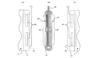
本発明では、図2(b)に示すように、巻回中心付近で一方側と他方側とに分けられた発電要素1の電極端部は、集電接続体2の電極接続部2bに各々接合される際に、一方側の接合領域A1が他方側の接合領域A2と比較して電極の集積度が小さくなるか又は接合部の総面積が小さくなるように、両者の接合領域の接合状態を異ならせている。本実施形態では、一方側の接合領域A1における接合部P1の溶接強度が、他方側の接合領域A2における接合部P2の溶接強度より小さい状態で、電極端部と電極接続部2bとが溶接されている例を示す。
In the present invention, as shown in FIG. 2 (b), the electrode end portions of the
本発明において、「接合領域」とは、全ての接合部と、接合部同士の間に非接合部が存在する場合にはその非接合部とを総和した領域を指す。また、「電極の集積度」とは、接合領域において積層状態で存在する電極の最外層を基準として、その最外層と接合前に存在した電極接続部の表面との間の体積に占める複数層の電極の総面積を指す。従って、電極の集積度の大小関係を比較するとき、接合領域における電極の面積が同じである場合(積層数も同じ)には、最外層を基準とする体積が大きい方が、電極の集積度が小さくなる。 In the present invention, the “joining region” refers to a region obtained by summing all the joining portions and, if there are non-joining portions between the joining portions, the non-joining portions. In addition, the “electrode integration degree” refers to a plurality of layers occupying the volume between the outermost layer and the surface of the electrode connection portion existing before joining, based on the outermost layer of the electrode existing in a laminated state in the joining region. The total area of the electrodes. Therefore, when comparing the degree of integration of the electrodes, if the area of the electrodes in the junction region is the same (the number of layers is the same), the larger the volume based on the outermost layer, the higher the degree of electrode integration. Becomes smaller.
図2(b)に示す例では、一方側の接合領域A1における接合部P1の溶接強度が、他方側の接合領域A2における接合部P2の溶接強度より小さい状態で溶接されているため、接合部P2の溶接強度がより大きい接合領域A2では、接合部P2において積層された電極端部が押し潰されて溶接され、電極の集積度が高くなっている。逆に、接合部P1の溶接強度がより小さい接合領域A1では、接合部P1において積層された電極端部が殆ど押し潰されていない状態で溶接され、電極の集積度が低くなっている。 In the example shown in FIG. 2B, since the weld strength of the joint portion P1 in the joint region A1 on one side is welded in a state smaller than the weld strength of the joint portion P2 in the joint region A2 on the other side, the joint portion In the joining region A2 where the welding strength of P2 is larger, the electrode end portions laminated at the joining portion P2 are crushed and welded, and the degree of electrode integration is high. On the contrary, in the joining region A1 where the welding strength of the joint P1 is smaller, welding is performed in a state where the electrode end portions laminated in the joint P1 are hardly crushed, and the degree of electrode integration is low.
接合部P1、P2の溶接強度を変える方法としては、付与するエネルギーやパワーを変化させる方法、エネルギーやパワーを付与する時間を変化させる方法、エネルギーやパワーを付与する媒体の圧接力を変化させる方法、エネルギーやパワーを付与する媒体の圧接部の形状を変化させる方法など、何れの方法も採用することができる。なかでも、エネルギー、パワー、又は圧力を変化させる方法が効果的である。 As a method of changing the welding strength of the joints P1 and P2, a method of changing energy and power to be applied, a method of changing time of applying energy and power, and a method of changing the pressure contact force of a medium to which energy and power are applied Any method such as a method of changing the shape of the press contact portion of the medium to which energy or power is applied can be adopted. Among them, a method of changing energy, power, or pressure is effective.
本実施形態において、一方側の接合領域A1における接合部P1の溶接強度をより小さくする際に、全ての接合部P1の溶接強度を小さくせずに、何れか一部の溶接強度をのみを小さくしてもよい。あるいは、1つの接合部P1の中で、部分的に溶接強度を小さくすることも可能である。 In this embodiment, when reducing the welding strength of the joint portion P1 in the joint region A1 on one side, the welding strength of all the joint portions P1 is not reduced, but only a part of the welding strength is reduced. May be. Alternatively, it is possible to partially reduce the welding strength in one joint P1.
また、本実施形態において、溶接強度を変える方法と併用して、後述するような、接合部P1、P2の数を変える方法、接合の総面積を変える方法、接合部同士の間隔を変える方法などを採用してもよい。 Further, in the present embodiment, in combination with a method of changing the welding strength, a method of changing the number of joints P1, P2 as described later, a method of changing the total area of the joint, a method of changing the interval between the joints, etc. May be adopted.
一方、集電接続体2,2は、正負極の端子4,4と共にステンレス鋼板製の蓋板5の両端部に取り付けられる。端子4,4は、蓋板5を上方から貫通してそれぞれ蓋板5の下方に配置した集電接続体2,2の本体2a,2aにカシメによって接続固定される。また、この際、集電接続体2,2と端子4,4との間に絶縁封止材を介在させることにより、端子4,4が蓋板5を貫通する孔を封止すると共に、集電接続体2,2や端子4,4とこの蓋板5との間を絶縁するようになっている。必要に応じて、電池容器6の内部の容積効率を高めるために、発電要素1の側面の上端のセパレータやこれを覆う絶縁シートを、集電接続体2の本体2aの下面に接するように間隙なく配置してもよい。
On the other hand, the
このようにして蓋板5の両端部に集電接続体2,2と端子4,4が取り付けられると、これらの集電接続体2,2の各対の電極接続部2bに上記のようにして発電要素1が接続される。そして、これら発電要素1は、ステンレス鋼板製の筐体状の電池容器6の内部に上方から挿入して収納され、この電池容器6の上端開口部が蓋板5によって塞ぐと共に、この蓋板5の周囲を溶接によって封止する。また、電池容器6の側面に開口した注液口6aから内部に電解液を注入し、この注液口6aを封口することにより非水電解質二次電池となる。
When the
本発明では、発電要素1の両端面から、迅速に電極1a,1b間に電解液が浸透するようになるので、この電解液の注液工程を迅速化することができるようになる。このようにして電解液が注入されると、注液口6aをレーザー溶接等により封口して非水電解質二次電池となる。上記実施形態では、非水電解質二次電池について示したが、他の二次電池や一次電池についても同様に実施可能であり、電池の種類は問わない。
In the present invention, since the electrolytic solution quickly penetrates between the
本発明は、電極端部が巻回中心付近で一方側と他方側とに分けられて、電極接続部2bに各々接合される際に、両者の接合領域の接合状態を異ならせている点のみが、従来の電池と相違する。従って、かかる点以外の構成については、従来公知の構成が何れも採用できる。
In the present invention, only when the electrode end portion is divided into one side and the other side in the vicinity of the winding center and joined to the
本発明者らは、本発明の電池の例として、図1〜図2に示す構造のリチウムイオン二次電池を試作して、板状の電極接続部2bの両側で同じ溶接強度の従来品と、比較した。その結果、電極接続部2bの一方の溶接強度を他方の溶接強度の約半分にした本発明品は、従来品に対して、電解液の注液時間が1/5程度となり、内部抵抗も2/3になり、充放電サイクル時(100サイクル)の電池の膨れも半分程度となった。なお、電極接続部2bの両側ともに、溶接強度の約半分にした比較品では、注液時間等は改善されるものの、内部抵抗が大きくなるという問題があった。
As an example of the battery of the present invention, the inventors made a trial manufacture of a lithium ion secondary battery having the structure shown in FIGS. 1 to 2 and a conventional product having the same welding strength on both sides of the plate-like
(他の実施形態)
(1)前記の実施形態では、一方側の接合領域が他方側の接合領域と比較して電極の集積度が小さくなるように、一方側と他方側の溶接強度を変える例を示したが、集積度を変える方法はこれに限定されず、接合部P1、P2の数を変える方法、接合の総面積を変える方法、接合部同士の間隔を変える方法などを採用してもよい。また、これらの方法を複数併用してもよい。なお、接合方法としては、溶接による方法が好ましいが、ソルダ接合、カシメ接合、導電結着剤なども採用することが可能である。
(Other embodiments)
(1) In the above-described embodiment, an example in which the welding strength on one side and the other side is changed so that the joining region on one side is smaller than the joining region on the other side is shown. The method of changing the degree of integration is not limited to this, and a method of changing the number of junctions P1 and P2, a method of changing the total area of junctions, a method of changing the interval between junctions, and the like may be adopted. A plurality of these methods may be used in combination. In addition, as a joining method, the method by welding is preferable, However, Solder joining, caulking joining, a conductive binder, etc. are also employable.
接合部P1、P2の数を変える方法としては、図3に示すように、一方側の接合領域A1における接合部P1の数が、他方側の接合領域A2における接合部P2の数より少ないものが例示できる。接合部が少なくなると、非接合部の面積が増えるため、その部分での電極の集積度が小さくなり、そこから電解液の浸透やガスの排出が行い易くなる。 As a method for changing the number of the joint portions P1 and P2, as shown in FIG. 3, the number of the joint portions P1 in the joint region A1 on one side is smaller than the number of the joint portions P2 in the joint region A2 on the other side. It can be illustrated. When the number of joints is reduced, the area of the non-joint part is increased, so that the degree of electrode integration at that part is reduced, and it is easy to permeate the electrolyte and discharge gas therefrom.
この例では、接合領域A1における接合部P1の数2に対して、接合領域A2における接合部P2の数を3としているが、1箇所対2箇所、2箇所対4箇所、3箇所対4箇所など、何れの組合せでもよい。
In this example, the number of joints P2 in the joint region A2 is set to 3 with respect to the
この例では、接合部の数を変えることにより、同時に一方側の接合領域A1における接合部同士の間隔が、他方側の接合領域A2における接合部同士の間隔より広い例となっている。このように、接合部同士の間隔が広がることで、電極の集積度が小さい部分が増加することになり、そこから電解液の浸透やガスの排出が行い易くなる。 In this example, by changing the number of joints, the spacing between joints in the joint region A1 on one side is wider than the spacing between joints in the joint region A2 on the other side. As described above, when the interval between the joint portions is widened, the portion where the degree of integration of the electrodes is small increases, and it becomes easy to permeate the electrolyte and discharge the gas therefrom.
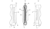
また、接合の総面積を変える方法としては、図4に示すように、一方側の接合領域A1における接合の総面積が、他方側の接合領域A2における接合の総面積より少ないものが例示できる。接合の総面積が少なくなると、接合部P1間の非接合部の面積が増えるため、その部分での電極の集積度が小さくなり、そこから電解液の浸透やガスの排出が行い易くなる。 Further, as a method of changing the total area of bonding, as shown in FIG. 4, a method in which the total area of bonding in the bonding area A1 on one side is smaller than the total area of bonding in the bonding area A2 on the other side can be exemplified. When the total area of the junction is reduced, the area of the non-joint portion between the joint portions P1 is increased, so that the degree of electrode integration at that portion is reduced, and it is easy to permeate the electrolyte and discharge the gas therefrom.
この例では、同時に一方側の接合領域A1における接合部同士の間隔が、他方側の接合領域A2における接合部同士の間隔より広くなっているが、接合部同士の間隔を同じにしながら、一方側の接合領域A1における接合の総面積を、他方側の接合領域A2における接合の総面積より少なくすることも可能である。 In this example, the interval between the joint portions in the joint region A1 on one side is wider than the interval between the joint portions in the joint region A2 on the other side at the same time. It is possible to make the total area of the junction in the junction area A1 smaller than the total area of the junction in the other junction area A2.
本発明では、一方側の接合領域が他方側の接合領域と比較して、電極の集積度を小さくする代わりに、接合部の総面積が小さくなるようにしてもよく、また、電極の集積度を小さくすると同時に接合部の総面積を小さくしてもよい。なお、図4に示す例は、電極の集積度を小さくすると同時に接合部の総面積を小さくした例に相当する。 In the present invention, instead of reducing the integration degree of the electrode on one side compared to the bonding area on the other side, the total area of the junction may be reduced. At the same time, the total area of the joint may be reduced. Note that the example shown in FIG. 4 corresponds to an example in which the degree of integration of the electrodes is reduced and at the same time the total area of the junction is reduced.
接合部の総面積のみを小さくした例としては、図5に示すように、一方側の接合領域A1における接合の総面積が、他方側の接合領域A2における接合の総面積より少ないものが例示できる。接合の総面積が少なくなると、接合部P1の上下の非接合部の面積が増えるため、その部分から電解液の浸透やガスの排出が行い易くなる。 As an example in which only the total area of the joint portion is reduced, as shown in FIG. 5, an example in which the total area of the junction in the one-side junction area A1 is smaller than the total area of the junction in the other-side junction area A2 can be exemplified. . When the total area of the junction is reduced, the areas of the upper and lower non-joined portions of the joined portion P1 are increased, so that it is easy to infiltrate the electrolyte and discharge the gas from that portion.
また、本発明では、図6に示すように、一方側の接合領域A1における接合部P1と、他方側の接合領域A2における接合部P2とを、上下に互い違いに設けてもよい。このように、一方側の接合領域A1における非接合部に、他方側の接合領域A2における接合部を対向させて設けることにより、製造がより容易になるという効果が得られる。 Moreover, in this invention, as shown in FIG. 6, you may provide the junction part P1 in the junction area | region A1 of one side, and the junction part P2 in the junction area | region A2 of the other side alternately up and down. As described above, by providing the non-joining portion in the one-side joining region A1 so as to face the joining portion in the other-side joining region A2, it is possible to obtain an effect that manufacturing becomes easier.
(2)前記の実施形態では、電極接続部の表面が平坦な場合の例を示したが、溶着による接合をより確実なものにする目的で、板面から突出する凸部を設けてもよい。その場合、板面から突出する凸部が適宜間隔で複数箇所ずつ形成される。電極接続部に金属箔と重なり合う凸部が形成されていると、これらの金属箔が各凸部で集中的に超音波のエネルギーを受けるようになり、溶着による接合を確実なものにすることができる。本発明では、このような凸部の形状や数を変化させて、一方側と他方側の溶接強度を変えてもよい。 (2) In the above-described embodiment, an example in which the surface of the electrode connecting portion is flat has been described. However, a convex portion protruding from the plate surface may be provided for the purpose of ensuring the bonding by welding. . In that case, a plurality of convex portions protruding from the plate surface are formed at appropriate intervals. If convex portions that overlap with the metal foil are formed in the electrode connection portion, these metallic foils will receive ultrasonic energy intensively at each convex portion, and it is possible to ensure bonding by welding it can. In the present invention, the welding strength on one side and the other side may be changed by changing the shape and number of such convex portions.
なお、接合部P1、P2に存在する電極接続部と電極端部とを予め挟持板で挟み込んでおき、溶接を行うことも可能である。その場合、電解液の浸透性を高めるために、接合部間や接合領域周辺に存在する非接合部が、挟持板で覆われないようにするのが好ましい。挟持板としては、短冊状の比較的薄い金属板を長手方向に沿って中央で二つ折りにした挟持板などが用いられ、正極側にはアルミニウム合金板の挟持板が用いられ、負極側には銅合金板の挟持板が用いられる。 It is also possible to perform welding by previously sandwiching the electrode connecting portion and the electrode end portion existing in the joint portions P1 and P2 with a sandwiching plate. In that case, in order to improve the permeability of the electrolytic solution, it is preferable that non-joining portions existing between the joining portions and around the joining region are not covered with the sandwiching plate. As the sandwiching plate, a sandwiching plate obtained by folding a strip-shaped relatively thin metal plate in the center along the longitudinal direction is used, and a sandwiching plate of an aluminum alloy plate is used on the positive electrode side, and a sandwiching plate on the negative electrode side. A copper alloy plate clamping plate is used.
(3)前記の実施形態では、集電接続体の電極接続部が、発電要素の巻回中心付近にて内部に挿入された板状部で形成され、その板状部の両面に電極端部が各々接合されている例を示したが、図7に示す従来技術と同様に、1つの発電要素1の片側の電極端部に接合される電極接続部2bは、2本であってもよい。その場合、一方の電極接続部2bの接合領域が、他方の電極接続部2bの接合領域と比較して、電極の集積度が小さくなるように、両者の接合領域の接合状態を異ならせる。
(3) In the above-described embodiment, the electrode connection portion of the current collector connection member is formed of a plate-like portion inserted therein in the vicinity of the winding center of the power generation element, and electrode end portions are formed on both surfaces of the plate-like portion. However, as in the related art shown in FIG. 7, the number of
2本の電極接続部2bを設ける場合、発電要素1は、一方の端部にはみ出した長円筒形の正極1aのアルミニウム箔の直線部が、巻回中心付近で一方側と他方側とに分けられ、各々の電極接続部2bに接合される。また、発電要素1の他方の端部にはみ出した長円筒形の負極1bの銅箔の直線部も、同様にして、各電極接続部2bに接合される。その際、各々の電極接続部2bは、発電要素1の電極端部の内側に挿入されてもよく、電極端部の外側に沿って配置されてもよい。
When the two
なお、上記実施形態では、1個の発電要素1を有する非水電解質二次電池について示したが、2個以上の任意個の発電要素1を有する非水電解質二次電池にも同様に実施可能である。さらに、金属箔等の電極基体に活物質が塗布されたままでも集電可能であれば、これら活物質が塗布されたままの電極1a,1bに集電接続体をそのまま接続することもでき、電極基体を用いない電極に集電接続体を接続することもできる。
In the above embodiment, a non-aqueous electrolyte secondary battery having one
(4)前記の実施形態では、長円筒形に巻回した発電要素1を用いる場合について示したが、本発明では、長円筒形などのような偏平型の発電要素1に限らず、円筒形の発電要素1を用いることも可能である。但し、電気的接続の簡便性などの観点から、偏平型の発電要素1を用いることが好ましい。
(4) In the above embodiment, the case where the
1 発電要素
1a 正極
1b 負極
2 集電接続体
2b 電極接続部
4 端子
6 電池容器
A1 一方側の接合領域
A2 他方側の接合領域
P1 一方側の接合部
P2 他方側の接合部
DESCRIPTION OF
Claims (6)
前記発電要素の電極端部は、巻回中心付近で一方側と他方側とに分けられて、前記集電接続体の電極接続部に各々接合されていると共に、前記一方側の接合領域が前記他方側の接合領域と比較して電極の集積度が小さくなるか又は接合部の総面積が小さくなるように、両者の接合領域の接合状態を異ならせていることを特徴とする電池。 A power generation element in which an electrode is wound, a battery container that houses the power generation element, a current collector connection that collects current from the power generation element, and a terminal that is electrically connected to the current collector connection In batteries,
The electrode end portion of the power generation element is divided into one side and the other side in the vicinity of the winding center, and is joined to the electrode connection portion of the current collector connection body, and the joint region on the one side is A battery characterized in that the bonding states of both bonding regions are made different so that the degree of integration of the electrodes becomes smaller or the total area of the bonding portion becomes smaller than the bonding region on the other side.
3. The battery according to claim 1, wherein an interval between the bonding portions in the bonding region on the one side is wider than an interval between bonding portions in the bonding region on the other side.
Priority Applications (1)
| Application Number | Priority Date | Filing Date | Title |
|---|---|---|---|
| JP2011056678A JP2012195085A (en) | 2011-03-15 | 2011-03-15 | Battery |
Applications Claiming Priority (1)
| Application Number | Priority Date | Filing Date | Title |
|---|---|---|---|
| JP2011056678A JP2012195085A (en) | 2011-03-15 | 2011-03-15 | Battery |
Publications (1)
| Publication Number | Publication Date |
|---|---|
| JP2012195085A true JP2012195085A (en) | 2012-10-11 |
Family
ID=47086812
Family Applications (1)
| Application Number | Title | Priority Date | Filing Date |
|---|---|---|---|
| JP2011056678A Pending JP2012195085A (en) | 2011-03-15 | 2011-03-15 | Battery |
Country Status (1)
| Country | Link |
|---|---|
| JP (1) | JP2012195085A (en) |
Cited By (2)
| Publication number | Priority date | Publication date | Assignee | Title |
|---|---|---|---|---|
| WO2014024522A1 (en) * | 2012-08-06 | 2014-02-13 | トヨタ自動車株式会社 | Cell |
| EP2755258A1 (en) | 2013-01-11 | 2014-07-16 | GS Yuasa International Ltd. | Electric storage device, electric storage system, and manufacturing method thereof |
Citations (3)
| Publication number | Priority date | Publication date | Assignee | Title |
|---|---|---|---|---|
| JP2000150306A (en) * | 1998-11-12 | 2000-05-30 | Toyota Motor Corp | Battery or capacitor current collection method |
| WO2010001975A1 (en) * | 2008-07-02 | 2010-01-07 | 株式会社ジーエス・ユアサコーポレーション | Battery and method of manufacturing same |
| WO2010147136A1 (en) * | 2009-06-17 | 2010-12-23 | 株式会社Gsユアサ | Battery and method for producing battery |
-
2011
- 2011-03-15 JP JP2011056678A patent/JP2012195085A/en active Pending
Patent Citations (3)
| Publication number | Priority date | Publication date | Assignee | Title |
|---|---|---|---|---|
| JP2000150306A (en) * | 1998-11-12 | 2000-05-30 | Toyota Motor Corp | Battery or capacitor current collection method |
| WO2010001975A1 (en) * | 2008-07-02 | 2010-01-07 | 株式会社ジーエス・ユアサコーポレーション | Battery and method of manufacturing same |
| WO2010147136A1 (en) * | 2009-06-17 | 2010-12-23 | 株式会社Gsユアサ | Battery and method for producing battery |
Cited By (6)
| Publication number | Priority date | Publication date | Assignee | Title |
|---|---|---|---|---|
| WO2014024522A1 (en) * | 2012-08-06 | 2014-02-13 | トヨタ自動車株式会社 | Cell |
| JP2014032936A (en) * | 2012-08-06 | 2014-02-20 | Toyota Motor Corp | battery |
| US9343731B2 (en) | 2012-08-06 | 2016-05-17 | Toyota Jidosha Kabushiki Kaisha | Battery comprising a liquid inlet for electrolyte injection |
| EP2755258A1 (en) | 2013-01-11 | 2014-07-16 | GS Yuasa International Ltd. | Electric storage device, electric storage system, and manufacturing method thereof |
| KR20140091480A (en) | 2013-01-11 | 2014-07-21 | 가부시키가이샤 지에스 유아사 | Energy storage device, energy storage system, and method |
| US9431680B2 (en) | 2013-01-11 | 2016-08-30 | Gs Yuasa International Ltd. | Electric storage device, electric storage system, and manufacturing method thereof |
Similar Documents
| Publication | Publication Date | Title |
|---|---|---|
| KR100590006B1 (en) | Secondary Battery and Electrode Assembly Used in the Same | |
| JP5211086B2 (en) | Secondary battery | |
| JP6363893B2 (en) | Secondary battery | |
| JP6191588B2 (en) | Manufacturing method of secondary battery | |
| JP4292365B2 (en) | battery | |
| JP7662695B2 (en) | Terminal manufacturing method | |
| CN103534838B (en) | The manufacture method of negative-electrode terminal for cell and negative-electrode terminal for cell | |
| JP5594901B2 (en) | Secondary battery | |
| CN104685667A (en) | Method for manufacturing electrical storage device, auxiliary plate for ultrasonic welding, and electrical storage device | |
| WO2013154155A1 (en) | Electric storage device and secondary cell | |
| JP2002231214A (en) | Battery | |
| JP5176312B2 (en) | Battery pack and manufacturing method thereof | |
| JPWO2018159197A1 (en) | Secondary battery | |
| JP2013077467A (en) | Electrochemical device | |
| JP4096162B2 (en) | battery | |
| JP7606970B2 (en) | Prismatic secondary battery and its manufacturing method | |
| JP6159719B2 (en) | Electricity storage element | |
| JP2022112412A (en) | Terminal component, secondary battery, and battery pack | |
| JP2016139491A (en) | Power storage element | |
| JP2010219268A (en) | Storage device and storage module | |
| JP2004213937A (en) | battery | |
| JP5440663B2 (en) | battery | |
| JP2012195085A (en) | Battery | |
| CN101946345A (en) | Method for producing an individual cell for a battery | |
| JP7285817B2 (en) | SEALED BATTERY AND METHOD OF MANUFACTURING SEALED BATTERY |
Legal Events
| Date | Code | Title | Description |
|---|---|---|---|
| RD04 | Notification of resignation of power of attorney |
Free format text: JAPANESE INTERMEDIATE CODE: A7424 Effective date: 20130708 |
|
| A621 | Written request for application examination |
Free format text: JAPANESE INTERMEDIATE CODE: A621 Effective date: 20140311 |
|
| A977 | Report on retrieval |
Free format text: JAPANESE INTERMEDIATE CODE: A971007 Effective date: 20140820 |
|
| A131 | Notification of reasons for refusal |
Free format text: JAPANESE INTERMEDIATE CODE: A131 Effective date: 20140826 |
|
| A131 | Notification of reasons for refusal |
Free format text: JAPANESE INTERMEDIATE CODE: A131 Effective date: 20150407 |
|
| A02 | Decision of refusal |
Free format text: JAPANESE INTERMEDIATE CODE: A02 Effective date: 20151208 |