JP2012196018A - Wiring structure of three-phase motor - Google Patents
Wiring structure of three-phase motor Download PDFInfo
- Publication number
- JP2012196018A JP2012196018A JP2011056844A JP2011056844A JP2012196018A JP 2012196018 A JP2012196018 A JP 2012196018A JP 2011056844 A JP2011056844 A JP 2011056844A JP 2011056844 A JP2011056844 A JP 2011056844A JP 2012196018 A JP2012196018 A JP 2012196018A
- Authority
- JP
- Japan
- Prior art keywords
- phase
- stator
- housing
- parallel circuit
- conductive wire
- Prior art date
- Legal status (The legal status is an assumption and is not a legal conclusion. Google has not performed a legal analysis and makes no representation as to the accuracy of the status listed.)
- Withdrawn
Links
- 230000007935 neutral effect Effects 0.000 claims description 35
- 238000010276 construction Methods 0.000 claims 2
- 238000004804 winding Methods 0.000 description 29
- 229920003002 synthetic resin Polymers 0.000 description 9
- 239000000057 synthetic resin Substances 0.000 description 9
- 239000000758 substrate Substances 0.000 description 6
- 238000002788 crimping Methods 0.000 description 4
- 230000008901 benefit Effects 0.000 description 3
- 239000011810 insulating material Substances 0.000 description 3
- 238000009413 insulation Methods 0.000 description 3
- 230000009467 reduction Effects 0.000 description 3
- YCKRFDGAMUMZLT-UHFFFAOYSA-N Fluorine atom Chemical compound [F] YCKRFDGAMUMZLT-UHFFFAOYSA-N 0.000 description 2
- 239000011248 coating agent Substances 0.000 description 2
- 238000000576 coating method Methods 0.000 description 2
- 238000007796 conventional method Methods 0.000 description 2
- 230000003247 decreasing effect Effects 0.000 description 2
- 238000010586 diagram Methods 0.000 description 2
- 239000011737 fluorine Substances 0.000 description 2
- 229910052731 fluorine Inorganic materials 0.000 description 2
- 239000000463 material Substances 0.000 description 2
- 238000000034 method Methods 0.000 description 2
- 230000002093 peripheral effect Effects 0.000 description 2
- 238000005476 soldering Methods 0.000 description 2
- XEEYBQQBJWHFJM-UHFFFAOYSA-N Iron Chemical group [Fe] XEEYBQQBJWHFJM-UHFFFAOYSA-N 0.000 description 1
- 229910000831 Steel Inorganic materials 0.000 description 1
- 230000008859 change Effects 0.000 description 1
- 239000006185 dispersion Substances 0.000 description 1
- 238000010030 laminating Methods 0.000 description 1
- WABPQHHGFIMREM-UHFFFAOYSA-N lead(0) Chemical compound [Pb] WABPQHHGFIMREM-UHFFFAOYSA-N 0.000 description 1
- 230000007246 mechanism Effects 0.000 description 1
- 239000002184 metal Substances 0.000 description 1
- 229910052751 metal Inorganic materials 0.000 description 1
- 230000005405 multipole Effects 0.000 description 1
- 230000008569 process Effects 0.000 description 1
- 229920005989 resin Polymers 0.000 description 1
- 239000011347 resin Substances 0.000 description 1
- 239000010959 steel Substances 0.000 description 1
- 238000003466 welding Methods 0.000 description 1
Images





Classifications
-
- Y—GENERAL TAGGING OF NEW TECHNOLOGICAL DEVELOPMENTS; GENERAL TAGGING OF CROSS-SECTIONAL TECHNOLOGIES SPANNING OVER SEVERAL SECTIONS OF THE IPC; TECHNICAL SUBJECTS COVERED BY FORMER USPC CROSS-REFERENCE ART COLLECTIONS [XRACs] AND DIGESTS
- Y02—TECHNOLOGIES OR APPLICATIONS FOR MITIGATION OR ADAPTATION AGAINST CLIMATE CHANGE
- Y02T—CLIMATE CHANGE MITIGATION TECHNOLOGIES RELATED TO TRANSPORTATION
- Y02T10/00—Road transport of goods or passengers
- Y02T10/60—Other road transportation technologies with climate change mitigation effect
- Y02T10/64—Electric machine technologies in electromobility
Landscapes
- Windings For Motors And Generators (AREA)
- Insulation, Fastening Of Motor, Generator Windings (AREA)
Abstract
Description
本発明は、三相モータの配線構造に関する。 The present invention relates to a wiring structure of a three-phase motor.
従来の三相モータの配線構造を図7〜図9を参照して説明する。
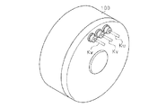
図9に示す三相モータは、ハウジング100内に配置された環状のステータ102には複数のコア101が環状に配置されるとともに、前記各コア101にはU,V,W相の順にステータコイル103が巻回されている。又、ハウジング100は、前記ステータ102の内周側に配置されるとともに永久磁石105を周部に備えたロータ104を回転可能に支持している。各ステータコイル103はハウジング100外の図示しない電源に接続される。
A wiring structure of a conventional three-phase motor will be described with reference to FIGS.
In the three-phase motor shown in FIG. 9, a plurality of
上記の三相モータは、複数極/複数スロットの構成を有している。例えば、三相モータを32極36スロットで構成する場合、図8に示すように、各コア101に巻回されたステータコイル103を3つ直列接続するとともに、この直列回路を一組として、4組の並列回路を各相分とし、各相分の並列回路が、例えばスター結線されている。
The above three-phase motor has a configuration of multiple poles / multiple slots. For example, when a three-phase motor is configured with 32 poles and 36 slots, as shown in FIG. 8, three
図8に示すように、従来は、各相のステータコイル103は、前記直列回路では同図に黒点で示す箇所(結線箇所K)で、ステータコイル103同士が結線されている。又、各相の並列回路の中性線側及び電源側は同図に示すように、複数の結線箇所Kt,Kdにおいて、結線されている。
As shown in FIG. 8, conventionally, the
具体的には、図9に示すように、ハウジング100内のステータ102の側方において、ブラケット112を介して固定されたリング状の基板110が配置されている。又、基板110上には、各相毎に結線用のバスバーと中性線のための結線用のバスバーと合わせて4つのバスバーが設けられ、それらのバスバーに設けられた複数の接続孔に対して各相の前記直列回路の電源側端、前記直列回路の中性線側端がそれぞれ差し込まれて溶接等により接続されることにより、前記結線箇所Kt,Kdが構成されている。
Specifically, as shown in FIG. 9, a ring-
そして、基板110の前記各相のバスバーには各相の単一のパワーケーブルKu,Kv,Kwがそれぞれ接続され、図7及び図9に示すように、ハウジング100から外部に導出されている。パワーケーブルKu,Kv,Kwの先端は、図8に示すようにそれぞれコネクタ120u,120v,120wが接続されている。
A single power cable Ku, Kv, Kw of each phase is connected to the bus bar of each phase of the
又、図8に示す、各直列回路を構成するコイル間の結線箇所Kは、それぞれ半田付けにより接続されている(以下、この従来技術を従来技術1という)。
しかしながら、上記の三相モータの配線構造では、各コイル間を半田付けする必要があるとともに、ステータの側方にブラケットを介して基板を設けるため、ハウジングにおいてロータの軸心方向の長さが長くなり大型化する問題があるとともに、結線箇所が多く配線コストが増える。
Further, the connection points K between the coils constituting each series circuit shown in FIG. 8 are connected by soldering (hereinafter, this prior art is referred to as prior art 1).
However, in the above three-phase motor wiring structure, the coils need to be soldered and a substrate is provided on the side of the stator via a bracket, so that the length of the rotor in the axial direction is long in the housing. In addition to the problem of increasing the size, there are many connection points, and the wiring cost increases.
前記配線コストの低減、及び、モータの小型化を図るために、従来から、三相モータの配線コストを低減するために、種々の方法が提案されている。
又、特許文献1のインホイールモータでは、環状のステータコアにステータコイルを巻回した複数のボビンが配列されて、前記各ボビンにステータコイルからの配線を支持するホルダ部が設けられている。前記ホルダ部に支持された前記各相の配線はハウジング内に設けられた基板の各相別の端子に対して接続されている。そして、前記基板の各相の端子には、電源に接続された各相のパワーケーブルが接続されている(以下、この従来技術を従来技術2という)。
In order to reduce the wiring cost and reduce the size of the motor, various methods have been proposed in the past in order to reduce the wiring cost of the three-phase motor.
In the in-wheel motor of Patent Document 1, a plurality of bobbins each having a stator coil wound around an annular stator core are arranged, and each bobbin is provided with a holder portion that supports wiring from the stator coil. The wiring of each phase supported by the holder portion is connected to a terminal for each phase of a substrate provided in the housing. Each phase terminal of the substrate is connected to a power cable for each phase connected to a power source (hereinafter, this prior art is referred to as prior art 2).
この構成により、インホイールモータの車幅方向の縮小化してインホイールモータを小型化することができる利点がある。
特許文献2では、鉄心に巻回した複数のコイルを環状に配置してステータを構成し、各コイルの径方向の内側から引き出した巻線の端部を結線端子を介して、多角形状に形成した中性点バスリングに対して結線することが提案されている(以下、この従来技術を従来技術3という)。このことにより、結線作業を容易化できる利点がある。
With this configuration, there is an advantage that the in-wheel motor can be reduced in size by reducing the in-wheel motor in the vehicle width direction.
In Patent Document 2, a plurality of coils wound around an iron core are arranged in an annular shape to constitute a stator, and the end portions of windings drawn from the radial inner side of each coil are formed in a polygonal shape via connection terminals. It has been proposed to connect to the neutral point bus ring (hereinafter, this prior art will be referred to as prior art 3). This has the advantage that the wiring work can be facilitated.
特許文献3では、3相モータにおいて、各相の巻線一端側の最端部のコイルの前記巻線一端側部分を1番目の渡り線とし、各相の巻線他端側の最端部のコイルの前記巻線他端側部分を(n+1)番目の渡り線とし、各相毎に前記巻線一端側部分から数えて(i−1)番目のコイルとi番目のコイルの間をi番目の渡り線とし、各相の奇数番目の渡り線を各相毎に一つにまとめて結線して電源線とするとともに、各相の偶数番目の渡り線同士を各相間一つにまとめて結線して中性点とするようにしている(以下、この従来技術を従来技術4という)。この構成により、電源線及び中性点の結線本数を低減できる利点がある。 In Patent Document 3, in the three-phase motor, the winding one end side portion of the coil at the one end of the winding of each phase is defined as a first jumper, and the end of the winding at the other end of each phase. The other end portion of the winding of the coil of (n + 1) is the (n + 1) -th connecting wire, and the interval between the (i-1) -th coil and the i-th coil is counted from the one end portion of the winding for each phase. And connect the odd-numbered crossover wires of each phase together into one power source line for each phase, and even-numbered crossover wires of each phase together into each phase. The connection is made to be a neutral point (hereinafter, this conventional technique is referred to as the conventional technique 4). With this configuration, there is an advantage that the number of power supply lines and neutral points can be reduced.
上記従来技術1乃至従来技術4に見られる様に、一般にハウジング内で結線が行われているため、配線をするために用いる絶縁材料や、樹脂部品はフッ素系の材料を用いることが多くなり、コストアップの原因となる。 As seen in the above prior art 1 to prior art 4, since the wiring is generally performed in the housing, the insulating material used for wiring and the resin parts often use fluorine-based materials. It causes cost increase.
又、従来技術1のようにハウジング内で結線を行うために半田付けした場合、使用時にモータが高温になると、半田付けした結線箇所の信頼性確保が必要になる。
本発明の目的は、上記課題を解決して、結線箇所を少なくできると共に、結線作業を行いやすくすることができる三相モータの配線構造を提供することにある。
Further, when soldering is performed in order to perform connection within the housing as in the prior art 1, if the motor becomes hot during use, it is necessary to ensure the reliability of the soldered connection.
The objective of this invention is providing the wiring structure of the three-phase motor which solves the said subject and can make connection work easy while being able to reduce a connection location.
上記問題点を解決するために、請求項1の発明は、ハウジング内に配置されるとともに環状に配列されたステータコアを有するステータであって、直列に接続した同相の複数のステータコイルが各相順に前記ステータコアに巻回されたステータと、前記ステータ内に配置されて前記ハウジングに回転自在に支持されたロータを有する三相モータの配線構造において、前記直列に接続した同相の複数のステータコイル(以下、直列接続ステータコイル群という)は連続した1つの導電線により形成され、前記直列接続ステータコイル群は、各相毎に複数備えて、並列回路を構成し、前記各相の前記並列回路を構成する前記各導電線の電源側の一端は、前記ハウジング外部に導出されて互いに第1結線手段により結線されて、電源に接続可能にされ、前記各相の前記並列回路を構成する前記各導電線の中性点側の一端は、前記ハウジング外部に導出されて第2結線手段により互いに結線されていることを特徴とする三相モータの配線構造を要旨としている。 In order to solve the above problems, the invention of claim 1 is a stator having a stator core arranged in a housing and arranged in an annular shape, wherein a plurality of in-phase stator coils connected in series are arranged in order of each phase. In the wiring structure of a three-phase motor having a stator wound around the stator core and a rotor disposed in the stator and rotatably supported by the housing, a plurality of in-phase stator coils connected in series (hereinafter referred to as a “phase stator coil”) , A series connection stator coil group) is formed by one continuous conductive wire, and a plurality of the series connection stator coil groups are provided for each phase to form a parallel circuit, and the parallel circuit of each phase is configured. One end of each conductive wire on the power supply side is led out of the housing and connected to each other by the first connection means so that it can be connected to the power supply. One end of each conductive wire constituting the parallel circuit of each phase on the neutral point side is led out of the housing and connected to each other by a second connecting means. The main point is the wiring structure.
請求項2の発明は、請求項1において、前記各相の前記並列回路を構成する前記各導電線において、最も中性点側に位置するステータコイルから、前記中性点側の結線部位までの長さは、各相が互いに同じ長さになるように配置されていることを特徴とする。 A second aspect of the present invention is the first aspect of the present invention, wherein, in each of the conductive wires constituting the parallel circuit of each phase, from the stator coil located closest to the neutral point side to the connection portion on the neutral point side The length is characterized in that the phases are arranged so as to have the same length.
請求項3の発明は、請求項1又は請求項2において、前記第1結線手段は、前記電源と接続可能なコネクタ内に設けられていることを特徴とする。
請求項4の発明は、ハウジング内に配置されるとともに環状に配列されたステータコアを有するステータであって、ステータコイルが各相順に前記ステータコアに巻回されたステータと、前記ステータ内に配置されて前記ハウジングに回転自在に支持されたロータを有する三相モータの配線構造において、前記ステータコイルは1つの導電線により形成され、前記ステータコイルは、各相毎に複数備えて、並列回路を構成し、前記各相の前記並列回路を構成する前記各導電線の電源側の一端は、前記ハウジング外部に導出されて互いに第1結線手段により結線されて、電源に接続可能にされ、前記各相の前記並列回路を構成する前記各導電線の中性点側の一端は、前記ハウジング外部に導出されて第2結線手段により互いに結線されていることを特徴とする三相モータの配線構造を要旨としている。
A third aspect of the present invention is characterized in that, in the first or second aspect, the first connection means is provided in a connector connectable to the power source.
According to a fourth aspect of the present invention, there is provided a stator having a stator core disposed in a housing and arranged in an annular shape, wherein a stator coil is wound around the stator core in order of each phase, and is disposed in the stator. In the wiring structure of a three-phase motor having a rotor rotatably supported by the housing, the stator coil is formed by one conductive wire, and a plurality of the stator coils are provided for each phase to form a parallel circuit. The one end of each conductive wire constituting the parallel circuit of each phase on the power supply side is led out of the housing and connected to each other by the first connection means so that it can be connected to the power supply. One end on the neutral point side of each conductive wire constituting the parallel circuit is led out of the housing and connected to each other by the second connection means. It is summarized as wiring structure of a three-phase motor according to claim.
請求項5の発明は、請求項4において、前記各相の前記並列回路を構成する前記各導電線から、前記中性点側の結線部位までの長さは、各相が互いに同じ長さになるように配置されていることを特徴とする。 According to a fifth aspect of the present invention, in the fourth aspect, the length from each conductive wire constituting the parallel circuit of each phase to the connection portion on the neutral point side is the same for each phase. It arrange | positions so that it may become.
請求項6の発明は、請求項4又は請求項5において、前記第1結線手段は、前記電源と接続可能なコネクタ内に設けられていることを特徴とする。 According to a sixth aspect of the present invention, in the fourth or fifth aspect, the first connection means is provided in a connector connectable to the power source.
請求項1及び請求項4の発明によれば、従来に比して結線箇所を少なくできると共に、結線作業を行いやすくすることができる三相モータの配線構造を提供できる。
請求項2及び請求項5の発明によれば、各相のステータコイルから、中性点側の結線部位までの長さは、各相が互いに同じ長さになるように配置されていることにより、各相間において、抵抗値のばらつきを低減できる。
According to the first and fourth aspects of the present invention, it is possible to provide a wiring structure for a three-phase motor that can reduce the number of connection points as compared with the prior art and facilitate the connection work.
According to invention of Claim 2 and
請求項3及び請求項6の発明によれば、ハウジングの外部に配置されるコネクタ内で、各相の並列回路を構成する各導電線の電源側の一端を結線する第1結線手段を、コネクタにより覆い隠すことができる。 According to the third and sixth aspects of the present invention, the first connection means for connecting the power supply side one end of each conductive wire constituting the parallel circuit of each phase in the connector disposed outside the housing is provided with the connector. Can be covered.
以下、本発明の三相モータの配線構造をインホイールモータに具体化した一実施形態を図1〜図6を参照して説明する。なお、インホイールモータは、車体の左右後輪(或いは左右前輪)にそれぞれ設けられるが、説明の便宜上、本実施形態では、車体の右後輪に設けられたインホイールモータについて説明する。 Hereinafter, an embodiment in which the wiring structure of the three-phase motor of the present invention is embodied in an in-wheel motor will be described with reference to FIGS. The in-wheel motor is provided on each of the left and right rear wheels (or the left and right front wheels) of the vehicle body. However, for convenience of explanation, in the present embodiment, the in-wheel motor provided on the right rear wheel of the vehicle body will be described.
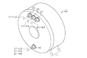
図1、図3(a)に示すように、インホイールモータ10のハウジング11は、有底円筒状のハウジング本体12と、ハウジング本体12の開口を覆うカバー体13とから構成されている。ハウジング本体12とカバー体13とは、図3(a)に示すように左右より結合されて図示しないボルト等により固定されている。ハウジング本体12は車体側から延出された図示しないストラット及び図示しないロアアームに連結されることにより、インホイールモータ10全体が図示しない車体に支持されている。
As shown in FIGS. 1 and 3A, the housing 11 of the in-
ハウジング11内にはロータ15が図3(a)において左右方向(車幅方向)に延びるように配設されて、その軸の両端がハウジング本体12及びカバー体13に対し、ベアリング17,18により回動自在に支持されている。又、前記軸の一端(右端)は、ハウジング本体12から外部に突出されるとともに図示しないギヤ機構を介して図示しないホイールハブに設けられたスピンドル軸に連結される。ロータ15の外周には複数の永久磁石16が固定されている。
A
ハウジング本体12の内周には、図3(a)、図4に示すように、環状のステータ20が固定されている。ステータ20は、多数枚の電磁鋼板を積層して形成されている。ステータ20の内周には、複数のステータコア21がロータ15の軸心に向かって突出されて環状に配置されている。又、ステータコア21は永久磁石16の外周に対してエアギャップを介して相対向するように配置されている。複数のステータコア21は、等間隔をおいて配置されている。各ステータコア21には、絶縁被膜が被覆されたステータコイル22が巻回された絶縁性合成樹脂からなる複数のボビン23が嵌合固定されている。
An
本実施形態では、インホイールモータ10は、ステータ20及びロータ15により、32極36スロットのモータとして構成されている。
ここで、U相のステータコイル22について説明する。
In the present embodiment, the in-
Here, the
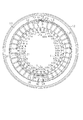
U相では、図2に示すように、3つのステータコイル22が直列接続された直列回路を4組有する。この4組の直列回路は、後述する第1結線手段及び第2結線手段により、互いに並列に接続されて並列回路を構成する。3つのステータコイル22からなる前記直列回路は、連続した1つの導電線により構成されている。前記直列回路は、直列接続ステータコイル群に相当する。
In the U phase, as shown in FIG. 2, there are four sets of series circuits in which three
図2では、U相の各ステータコイル22には、Unmの符号を付す。ここで、nは、並列回路の識別(本実施形態では1〜4)符号を示し、mは電源側に近位の順番(a〜c)を示す。又、各直列回路を構成する導電線には、前記nに合わせてそれぞれU1〜U4を付す。
In FIG. 2, each
V相及びW相のステータコイル22においてもU相と同数のステータコイル22により、U相と同様の直列回路並びに並列回路を有する。又、V相及びW相においても、3つのステータコイル22からなる前記直列回路は、連続した1つの導電線により構成されている。前記直列回路は、直列接続ステータコイル群に相当する。図2では、U相と同様に、V相及びW相のステータコイル22にVnm,Wnmの符号を付す。又、V相及びW相において、各直列回路を構成する導電線には、前記nに合わせてそれぞれV1〜V4、並びにW1〜W4を付す。
The V-phase and W-phase stator coils 22 also have the same series circuit and parallel circuit as the U-phase by the same number of stator coils 22 as the U-phase. Also in the V phase and the W phase, the series circuit including the three
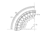
図4にはステータ20に配置された、U相,V相、W相に関するステータコイル22(U1a〜U1c,V1a〜V1c、W1a〜W1c、U2a〜U2c,V2a〜V2c、W2a〜W2c、U3a〜U3c,V3a〜V3c、W3a〜W3c、U4a〜U4c,V4a〜V4c、W4a〜W4c)の配置順を示している。図4に示すように、各相の3つのステータコイル22からなる前記直列回路は、U,V,Wの順にステータコア21に対して配置されている。図4に示すように、U1a〜U1c,V1a〜V1c、W1a〜W1cが順に配置されるともに、U2a〜U2c,V2a〜V2c、W2a〜W2cが順に配置される。又、同様にU3a〜U3c,V3a〜V3c、W3a〜W3c、並びにU4a〜U4c,V4a〜V4c、W4a〜W4cが順に配置されている。
In FIG. 4, stator coils 22 (U1a to U1c, V1a to V1c, W1a to W1c, U2a to U2c, V2a to V2c, W2a to W2c, U3a to U3a to U1c, U1a to U1c, which are arranged in the
U相において、導電線U1は、ステータコアU1a〜U1cを形成するように各ステータコア21に嵌合されたボビン23に順に巻回されている。又、ステータコイルU1aの巻始め部位から延びる電源側の部位は、図4、図3(a)において、P1で示す位置からカバー体13の左側壁に貫通して固定された絶縁性の絶縁性合成樹脂からなるグロメット25を介して外部に導出されている。又、導電線U1において、ステータコアU1cの巻終わり部位から中性点側の部位は、図3(a)、図4に示すように、カバー体13の内側面に沿って配置されるとともに、Q1で示す位置からカバー体13の左側壁に貫通して固定された絶縁性の絶縁性合成樹脂からなるグロメット30を介して外部に導出されている。なお、グロメット30の位置、グロメット25の位置とはロータ15の軸心を中心にして略180度反対位置に位置している。
In the U phase, the conductive wire U1 is wound around
又、図4に示す導電線U2は、ステータコアU2a〜U2cを形成するように各ステータコア21に嵌合されたボビン23に順に巻回されている。又、ステータコイルU2aの巻始め部位から延びる電源側の部位は、図4、図3(a)に示すようにカバー体13の内側面に沿って配置されるとともに、P2で示す位置から屈曲されて前記グロメット25を介して外部に導出されている。又、導電線U2において、ステータコアU2cの巻終わり部位から中性点側の部位は、図3(a)、図4に示すように、カバー体13の内側面に沿って配置されるとともに、Q2で示す位置で屈曲されてグロメット30を介して外部に導出されている。
Moreover, the conductive wire U2 shown in FIG. 4 is wound around the
図4に示す導電線U3は、ステータコアU3a〜U3cを形成するように各ステータコア21に嵌合されたボビン23に順に巻回されている。又、ステータコイルU3aの巻始め部位から延びる電源側の部位は、前記導電線U1,U2と同様にカバー体13の内側面に沿って配置されるとともに、P3で示す位置から前記グロメット25を介して外部に導出されている。又、導電線U3において、ステータコアU3cの巻終わり部位から中性点側の部位は、前記導電線U1,U2と同様にカバー体13の内側面に沿って配置されるとともに、図4に示すQ3で示す位置からグロメット30を介して外部に導出されている。
The conductive wire U3 shown in FIG. 4 is wound around a
図4に示す導電線U4は、ステータコアU4a〜U4cを形成するように各ステータコア21に嵌合されたボビン23に順に巻回されている。又、ステータコイルU4aの巻始め部位から延びる電源側の部位は、前記導電線U1,U2と同様にカバー体13の内側面に沿って配置されるとともに、P4で示す位置から前記グロメット25を介して外部に導出されている。又、導電線U4において、ステータコアU4cの巻終わり部位から中性点側の部位は、前記導電線U1,U2と同様にカバー体13の内側面に沿って配置されるとともに、図4に示すQ4で示す位置からグロメット30を介して外部に導出されている。
The conductive wire U4 shown in FIG. 4 is wound around a
又、導電線U1〜U4は、同じ仕様の導電線から形成されるとともに後述する電源側の第1結線手段及び中性点側の第2結線手段の間の電気抵抗が同じとなるように同じ長さを有している。又、各導電線U1〜U4において、各ステータコイルの巻数が同じ場合、各ステータコイルの巻長さの合計長と、各ステータコイル間を渡らせる導電線の長さの合計長は、いずれも同じである。一方、各導電線U1〜U4において、第1結線手段から、電気回路的に最も電源側に位置するステータコイル(Unmのmがaのもの)の巻始め迄の長さが異なる。このため、その分を電気回路的に最も中性点側に位置するステータコイル22(Unmのmがcのもの)の巻終わり位置から第2結線手段迄の長さを調整することにより、導電線U1〜U4の電気抵抗が同じとなるようにされている。 Further, the conductive lines U1 to U4 are formed of conductive lines having the same specifications, and have the same electrical resistance between the first connection means on the power source side and the second connection means on the neutral point side, which will be described later. It has a length. In addition, in each of the conductive wires U1 to U4, when the number of turns of each stator coil is the same, the total length of the winding length of each stator coil and the total length of the conductive wires that pass between the stator coils are all The same. On the other hand, in each of the conductive wires U1 to U4, the length from the first connecting means to the start of winding of the stator coil (where Unm is a) that is located closest to the power supply in the electric circuit is different. For this reason, by adjusting the length from the winding end position of the stator coil 22 (where U is m is c) located on the most neutral point side in the electric circuit to the second connection means, The electric resistances of the lines U1 to U4 are the same.
V相及びW相に関する導電線V1〜V4、W1〜W4においても、U相の導電線U1〜U4について上記説明したことと同様に構成することにより、図2に示す各ステータコイルV1a〜V1c、V2a〜V2c、V3a〜V3c、V4a〜V4c、W1a〜W1c、W2a〜W2c、W3a〜W3c、W4a〜W4cが構成されるとともに、ハウジング11内に配置されている。 Also in the conductive wires V1 to V4 and W1 to W4 related to the V phase and the W phase, the stator coils V1a to V1c shown in FIG. V2a to V2c, V3a to V3c, V4a to V4c, W1a to W1c, W2a to W2c, W3a to W3c, and W4a to W4c are configured and arranged in the housing 11.
図2に示す各導電線V1〜V4において、ステータコイルV1a、V2a,V3a,V4aの巻始め部位から延びる電源側の部位は、カバー体13の左側壁に貫通して固定された絶縁性の絶縁性合成樹脂からなるグロメット26(図1参照)を介して外部に導出されている。
In each of the conductive wires V1 to V4 shown in FIG. 2, the power supply side portion extending from the winding start portion of the stator coils V1a, V2a, V3a, V4a is insulative insulation that is fixed through the left side wall of the
又、各導電線V1〜V4において、ステータコアV1c〜V4cの巻終わり部位から中性点側の部位は、前記導電線U1〜U4と同様にカバー体13の内側面に沿って配置されるとともに、グロメット30を介して外部に導出されている。
Further, in each of the conductive wires V1 to V4, the portion on the neutral point side from the winding end portion of the stator cores V1c to V4c is arranged along the inner surface of the
図2に示す各導電線W1〜W4において、ステータコイルW1a、W2a,W3a,W4aの巻始め部位から延びる電源側の部位は、カバー体13の左側壁に貫通して固定された絶縁性の絶縁性合成樹脂からなるグロメット27(図1参照)を介して外部に導出されている。
In each of the conductive wires W1 to W4 shown in FIG. 2, the power supply side portion extending from the winding start portion of the stator coils W1a, W2a, W3a, W4a is insulative insulation that is fixed through the left side wall of the
又、各導電線W1〜W4において、ステータコアW1c〜W4cの巻終わり部位から中性点側の部位は、前記導電線U1〜U4と同様にカバー体13の内側面に沿って配置されるとともに、グロメット30を介して外部に導出されている。
Further, in each of the conductive wires W1 to W4, the portion on the neutral point side from the winding end portion of the stator cores W1c to W4c is arranged along the inner surface of the
図5には、上記のようにしてステータコイルが各ステータコア21に嵌合されたボビン23(図3参照)に巻回された巻方向が、示されている。同図において、○に黒丸の印は、紙面から表面方向に向かって巻回され、○に×の印は、紙面から裏面方向に向かって巻回されていることを示している。図5では全体の略1/4が示されているが残りの3/4は、図5に示した巻装状態が繰り返されている。
FIG. 5 shows the winding direction in which the stator coil is wound around the bobbin 23 (see FIG. 3) fitted to each
又、導電線V1〜V4、W1〜W4は、同じ仕様の導電線から形成されるとともに後述する電源側の第1結線手段及び中性点側の第2結線手段の間の電気抵抗が同じとなるように同じ長さを有している。又、各導電線V1〜V4、W1〜W4において、各ステータコイルの巻数が同じ場合、各ステータコイルの巻長さの合計長と、各ステータコイル間を渡らせる導電線の長さの合計長は、いずれも同じである。一方、各導電線V1〜V4、W1〜W4において、第1結線手段から、電気回路的に最も電源側に位置するステータコイル(Vnm,Wnmのmがaのもの)の巻始め迄の長さが異なる。このため、その分を電気回路的に最も中性点側に位置するステータコイル22(Vnm,Wnmのmがcのもの)の巻終わり位置から第2結線手段迄の長さを調整することにより、導電線V1〜V4、W1〜W4の電気抵抗が同じとなるようにされている。 The conductive lines V1 to V4 and W1 to W4 are formed of the same specification conductive lines and have the same electrical resistance between the first connection means on the power supply side and the second connection means on the neutral point side, which will be described later. So that they have the same length. In addition, in each of the conductive wires V1 to V4 and W1 to W4, when the number of turns of each stator coil is the same, the total length of the winding length of each stator coil and the total length of the conductive wires extending between the stator coils Are the same. On the other hand, in each of the conductive wires V1 to V4 and W1 to W4, the length from the first connection means to the start of winding of the stator coil (m of Vnm and Wnm where a is a) located on the most power supply side in the electric circuit Is different. Therefore, by adjusting the length from the winding end position to the second connection means of the stator coil 22 (m of Vnm, Wnm is c) which is located on the most neutral point side in the electric circuit. The electric resistances of the conductive lines V1 to V4 and W1 to W4 are the same.
グロメット25〜27を介して図1に示すようにハウジング11の外部に導出された各相の導電線U1〜U4、V1〜V4、W1〜W4は、それぞれコネクタに接続されている。コネクタに対する導電線の接続は、各相同じであるため、以下では、図3(a)、(b)に示すコネクタ40に対するU相の導電線U1〜U4の接続構造について説明する。なお、V相,W相のコネクタには、それぞれ図2に示すように符号60,70を付す。
As shown in FIG. 1 through the
図3(b)に示すように、コネクタ40は、コネクタハウジング42が絶縁性の合成樹脂から有底筒状に形成されたコネクタハウジング42と、コネクタハウジング42の底部に装着されるとともに、基端にカシメ部45を有し、先端に接続端子46を有するとともに雄型端子47から構成されている。コネクタハウジング42は、前記カシメ部45を覆う小径部42aと、接続端子46を覆うとともに、小径部42aよりも大径のフード部42bとから形成されている。
As shown in FIG. 3B, the
前記カシメ部45に対して前記導電線U1〜U4を束ねた状態でヒュージング(熱カシメ)が行われることにより前記カシメ部45と導電線U1〜U4とは一体に接続されている。この接続により、導電線U1〜U4は互いに結線されている。本実施形態では、前記カシメ部45が第1結線手段に相当する。
The
コネクタ40は、図示しない電源のU相に接続された図示しない雌型のコネクタと着脱自在に接続される。
グロメット30を介して図1に示すようにハウジング11の外部に導出された各相の導電線U1〜U4、V1〜V4、W1〜W4は、図3(b)、図6に示すように絶縁性の合成樹脂よりなる絶縁部材50内に固定された結線金具52に接続されている。
The
As shown in FIG. 1, the conductive wires U1 to U4, V1 to V4, and W1 to W4 of the phases led out to the outside of the housing 11 through the
結線金具52には、カシメ部54が形成され、前記カシメ部54に対して前記導電線U1〜U4、V1〜V4、W1〜W4を束ねた状態でヒュージング(熱カシメ)が行われることにより前記カシメ部54と導電線U1〜U4、V1〜V4、W1〜W4とは一体に接続されている。この接続により、導電線U1〜U4、V1〜V4、W1〜W4は互いに結線されて中性点を形成する。本実施形態では、前記カシメ部54が第2結線手段に相当する。
A
絶縁部材50は、前記カシメ部54を固定する部位(固定部)より反固定部側は筒状のフード50aが形成されている。フード50aにはキャップ56が着脱自在に螺着されてフード50aの開口が閉塞されている。キャップ56が絶縁部材50に着脱自在に螺着されることにより、フード50a内に一部露出した、結線金具52の点検が可能である。
The insulating
(実施形態の作用)
さて、上記のように構成されたインホイールモータ10の作用を説明する。
各相の導電線U1〜U4、V1〜V4、W1〜W4は、直列回路を構成するステータコイル22では、全て連続して巻回されてコイルが形成されている。
(Operation of the embodiment)
Now, the operation of the in-
The conductive wires U1 to U4, V1 to V4, and W1 to W4 of each phase are all wound continuously in the
このため、ステータコイル22に使用する導電線(マグネットワイヤ)を長くするのみで実施でき、直列回路を構成するステータコイル22間では結線作業が必要ではないため、低コスト化を図ることができる。
For this reason, it can implement only by lengthening the conductive wire (magnet wire) used for the
又、導電線U1〜U4、V1〜V4、W1〜W4において、各相において並列回路を構成する場合、全てハウジング11外部のコネクタ40,60,70の中で電源側の端部は結線されるとともに、中性点側は、ハウジング11外部の結線金具52により結線される。
In addition, when the parallel lines are formed in each phase in the conductive wires U1 to U4, V1 to V4, and W1 to W4, the ends on the power source side are all connected in the
このため、導電線の結線作業(本実施形態ではヒュージングで結線作業を行う)は、ハウジング11の外部で行うだけでよくなり、ハウジング内部で結線作業行う場合に比して、結線作業が行いやすい。 For this reason, the conductive wire connection work (in this embodiment, the connection work is performed by fusing) only needs to be performed outside the housing 11, and the connection work is performed as compared to the case where the connection work is performed inside the housing. Cheap.
又、本実施形態では、各導電線U1〜U4、V1〜V4、W1〜W4において、カシメ部45(第1結線手段)から、電気回路的に最も電源側に位置するステータコイル(Unm,Vnm,Wnmのmがaのもの)の巻始め迄の長さが異なる。このため、その分を電気回路的に最も中性点側に位置するステータコイル22(Unm,Vnm,Wnmのmがcのもの)の巻終わり位置からカシメ部54迄の長さを調整することにより、導電線U1〜U4、V1〜V4、W1〜W4の電気抵抗が同じとなるようにされている。このため、導電線U1〜U4、V1〜V4、W1〜W4における各相間の抵抗のばらつきがなくなる。
Further, in the present embodiment, in each of the conductive wires U1 to U4, V1 to V4, and W1 to W4, the stator coil (Unm, Vnm) that is located on the most power source side in terms of electrical circuit from the caulking portion 45 (first connection means). , Wnm m is a), and the length until the beginning of winding is different. For this reason, the length from the winding end position to the
本実施形態では、下記の特徴を有する。
(1) 本実施形態のインホイールモータ10は、直列に接続した同相の3つステータコイル22(直列接続ステータコイル群)は連続した1つの導電線U1〜U4、V1〜V4、W1〜W4により形成されている。又、前記直列接続ステータコイル群は、各相毎に複数備えて、並列回路を構成し、各相の前記並列回路を構成する各導電線U1〜U4、V1〜V4、W1〜W4の電源側の一端は、ハウジング11外部に導出されて互いに雄型端子47のカシメ部45(第1結線手段)により結線されて、電源に接続可能にされている。又、各相の前記並列回路を構成する各導電線U1〜U4、V1〜V4、W1〜W4の中性点側の一端は、ハウジング11外部に導出されて結線金具52のカシメ部54(第2結線手段)により互いに結線されている。
This embodiment has the following features.
(1) In the in-
この結果、本実施形態によれば、従来に比して結線箇所を少なくできると共に、結線作業を行いやすくすることができる。
又、従来、扁平形状で構成され、大トルクが求められるモータ、例えば、インホイールモータでは、大電流を流す必要があり、このため、モータが発熱量が大きいものが多い。このため、従来から、この種のモータは、150℃以上の高温領域において、使用されることが多い。
As a result, according to the present embodiment, the number of connection points can be reduced as compared with the conventional case, and the connection work can be easily performed.
Conventionally, a motor that is configured in a flat shape and requires a large torque, for example, an in-wheel motor, requires a large current to flow. Therefore, many motors generate a large amount of heat. For this reason, conventionally, this type of motor is often used in a high temperature region of 150 ° C. or higher.
150℃以上の高温領域において、使用されるモータは信頼性の確保のために、150℃以上の耐熱温度を持つ絶縁材料及び合成樹脂などを用いている。このため、フッ素系の材料を用いることが多くなり、コストアップの要因となっている。このようにコストアップを軽減するために、前記特許文献1〜特許文献3のコスト低減対策が提案されている。 In a high temperature region of 150 ° C. or higher, the motor used uses an insulating material or a synthetic resin having a heat resistant temperature of 150 ° C. or higher in order to ensure reliability. For this reason, a fluorine-based material is often used, which causes a cost increase. Thus, in order to reduce the cost increase, the cost reduction measures of Patent Documents 1 to 3 have been proposed.
本実施形態では、コスト低減のために、結線箇所を減少させることにより、結線処理の組立工数を、特に、多極多スロット形式のモータにおいて、大きな効果を奏することが期待できる。 In this embodiment, by reducing the number of connection locations for cost reduction, it can be expected that the number of assembly processes for the connection processing will be greatly improved, particularly in a multi-pole multi-slot motor.
具体的に、従来例と比較する。図8の従来例が、32極36スロットのモータを構成しているとすると、この場合、結線箇所は67箇所必要であるのに対して、本実施形態では、4箇所に激減することが分かる。 Specifically, it is compared with a conventional example. Assuming that the conventional example of FIG. 8 constitutes a motor with 32 poles and 36 slots, in this case, 67 connection points are required, whereas in this embodiment, it is drastically reduced to 4 locations. .
(2) 本実施形態のインホイールモータ10は、各相の前記並列回路を構成する各導電線U1〜U4、V1〜V4、W1〜W4において、最も中性点側に位置するステータコイルから、中性点側の結線部位までの長さは、各相が互いに同じ長さになるように配置されていることにより、各相間において、抵抗値のばらつきを低減できる。
(2) The in-
(3) 本実施形態のインホイールモータ10では、雄型端子47のカシメ部45(第1結線手段)は、電源と接続可能なコネクタ40,60,70内に設けられている。この結果、ハウジング11の外部に配置されるコネクタ40,60,70内で、各相の並列回路を構成する各導電線の電源側の一端を結線する雄型端子47のカシメ部45を、コネクタにより覆い隠すことができる。
(3) In the in-
なお、本発明の実施形態は前記実施形態に限定されるものではなく、下記のように変更しても良い。
・ 前記実施形態のモータはインホイールモータ10としたが、インホイールモータ10に限定されるものではなく、インホイールモータ10以外の他の三相モータに具体化してもよい。
In addition, embodiment of this invention is not limited to the said embodiment, You may change as follows.
-Although the motor of the said embodiment was set to the in-
・ 前記実施形態では、各相の導電線U1〜U4、V1〜V4、W1〜W4は、コネクタ40,60,70に、第1結線手段である雄型端子47のカシメ部45(第1結線手段)としたが、第1結線手段はコネクタの雄型端子47のカシメ部45に限定されない。例えば、カシメ部を有する接続金具の当該カシメ部で、まず各相の導電線U1〜U4、V1〜V4、W1〜W4を一旦互いにヒュージングで結線し、その接続金具と、コネクタに内装される接続端子とを単一のリード線等により接続を行うようにしてもよい。この場合、前記接続金具は、合成樹脂からなる絶縁カバー体で覆うものとする。
In the above-described embodiment, the conductive wires U1 to U4, V1 to V4, and W1 to W4 of each phase are connected to the
・ 前記実施形態では、インホイールモータ10を、32極36スロットのモータとして構成したが、極数及びスロット数は限定されるものではない。
例えば、前記実施形態では、直列接続ステータコイル群として、各相の導電線U1〜U4、V1〜V4、W1〜W4では、3つのステータコイル22で直列回路を構成した。
In the above embodiment, the in-
For example, in the above-described embodiment, as the series-connected stator coil group, each of the conductive wires U1 to U4, V1 to V4, and W1 to W4 of each phase configures a series circuit with three stator coils 22.
この構成の代わりに、各相の導電線U1〜U4、V1〜V4、W1〜W4において、1つのステータコイルのみを形成して、各相において、4つのステータコイルで並列回路を構成するようにしてもよい。この場合、ステータのコイル数に合わせて、ロータ側の永久磁石の数を減少させるとともに、他の構成は、前記実施形態と同様に構成するようにする。 Instead of this configuration, only one stator coil is formed in the conductive wires U1 to U4, V1 to V4, W1 to W4 of each phase, and a parallel circuit is configured with four stator coils in each phase. May be. In this case, the number of permanent magnets on the rotor side is reduced in accordance with the number of coils of the stator, and other configurations are configured in the same manner as in the above embodiment.
勿論、前記実施形態において、直列回路を構成するステータコイル22の数を増減したり、並列回路を構成する直列回路の数を増減するようにしてもよい。
・ なお、前記実施形態において、第2結線手段である結線金具52に変えて、コネクタとしてもよい。この場合、当該コネクタの構成は、前記実施形態のカシメ部45及び接続端子46を備える雄型端子47、及びコネクタ40と同様の構成とする。この場合、中性点を用いて充電を行うシステムの場合に、このコネクタを利用することができる。又、中性点の電位を知るために、このコネクタを利用することができる。
Of course, in the embodiment, the number of stator coils 22 constituting the series circuit may be increased or decreased, or the number of series circuits constituting the parallel circuit may be increased or decreased.
In addition, in the said embodiment, it may replace with the connection metal fitting 52 which is a 2nd connection means, and may be a connector. In this case, the configuration of the connector is the same as that of the male terminal 47 including the crimping
・ 前記コネクタは、雄型としたが、雌型であってもよい。
・ 前記実施形態では、結線作業をヒュージングで行ったが、各導電線の絶縁被覆をはぎ取った後、カシメ部45,54によりカシメ着したり、半田付けしてもよい。
The connector is a male type, but may be a female type.
In the above-described embodiment, the wiring work is performed by fusing. However, after the insulation coating of each conductive wire is peeled off, the crimping
U1〜U4…導電線、V1〜V4…導電線、W1〜W4…導電線、
11…ハウジング、15…ロータ、20…ステータ、
21…ステータコア、22…ステータコイル、
40,60,70…コネクタ。
U1-U4 ... conductive wire, V1-V4 ... conductive wire, W1-W4 ... conductive wire,
11 ... Housing, 15 ... Rotor, 20 ... Stator,
21 ... Stator core, 22 ... Stator coil,
40, 60, 70 ... connectors.
Claims (6)
前記ステータ内に配置されて前記ハウジングに回転自在に支持されたロータを有する三相モータの配線構造において、
前記直列に接続した同相の複数のステータコイル(以下、直列接続ステータコイル群という)は連続した1つの導電線により形成され、
前記直列接続ステータコイル群は、各相毎に複数備えて、並列回路を構成し、
前記各相の前記並列回路を構成する前記各導電線の電源側の一端は、前記ハウジング外部に導出されて互いに第1結線手段により結線されて、電源に接続可能にされ、
前記各相の前記並列回路を構成する前記各導電線の中性点側の一端は、前記ハウジング外部に導出されて第2結線手段により互いに結線されていることを特徴とする三相モータの配線構造。 A stator having a stator core arranged in a housing and arranged in an annular shape, wherein a plurality of in-phase stator coils connected in series are wound around the stator core in order of each phase;
In the wiring structure of a three-phase motor having a rotor disposed in the stator and rotatably supported by the housing,
A plurality of in-phase stator coils connected in series (hereinafter referred to as a series-connected stator coil group) are formed by one continuous conductive wire,
The series-connected stator coil group includes a plurality for each phase to constitute a parallel circuit,
One end on the power supply side of each conductive wire constituting the parallel circuit of each phase is led out of the housing and connected to each other by the first connection means, and can be connected to the power supply.
One end of each conductive wire constituting the parallel circuit of each phase on the neutral point side is led out of the housing and connected to each other by a second connecting means. Construction.
前記ステータ内に配置されて前記ハウジングに回転自在に支持されたロータを有する三相モータの配線構造において、
前記ステータコイルは1つの導電線により形成され、
前記ステータコイルは、各相毎に複数備えて、並列回路を構成し、
前記各相の前記並列回路を構成する前記各導電線の電源側の一端は、前記ハウジング外部に導出されて互いに第1結線手段により結線されて、電源に接続可能にされ、
前記各相の前記並列回路を構成する前記各導電線の中性点側の一端は、前記ハウジング外部に導出されて第2結線手段により互いに結線されていることを特徴とする三相モータの配線構造。 A stator having a stator core disposed in a housing and arranged in an annular shape, wherein a stator coil is wound around the stator core in order of each phase;
In the wiring structure of a three-phase motor having a rotor disposed in the stator and rotatably supported by the housing,
The stator coil is formed by one conductive wire,
A plurality of the stator coils are provided for each phase to constitute a parallel circuit,
One end on the power supply side of each conductive wire constituting the parallel circuit of each phase is led out of the housing and connected to each other by the first connection means, and can be connected to the power supply.
One end of each conductive wire constituting the parallel circuit of each phase on the neutral point side is led out of the housing and connected to each other by a second connecting means. Construction.
Priority Applications (1)
| Application Number | Priority Date | Filing Date | Title |
|---|---|---|---|
| JP2011056844A JP2012196018A (en) | 2011-03-15 | 2011-03-15 | Wiring structure of three-phase motor |
Applications Claiming Priority (1)
| Application Number | Priority Date | Filing Date | Title |
|---|---|---|---|
| JP2011056844A JP2012196018A (en) | 2011-03-15 | 2011-03-15 | Wiring structure of three-phase motor |
Publications (1)
| Publication Number | Publication Date |
|---|---|
| JP2012196018A true JP2012196018A (en) | 2012-10-11 |
Family
ID=47087445
Family Applications (1)
| Application Number | Title | Priority Date | Filing Date |
|---|---|---|---|
| JP2011056844A Withdrawn JP2012196018A (en) | 2011-03-15 | 2011-03-15 | Wiring structure of three-phase motor |
Country Status (1)
| Country | Link |
|---|---|
| JP (1) | JP2012196018A (en) |
Cited By (4)
| Publication number | Priority date | Publication date | Assignee | Title |
|---|---|---|---|---|
| WO2015076209A1 (en) * | 2013-11-19 | 2015-05-28 | Ntn株式会社 | Drive/turn module, and vehicle provided with drive/turn module |
| JP2015211603A (en) * | 2014-04-30 | 2015-11-24 | 三菱電機株式会社 | Motor, sealed type compressor, and refrigerating cycle device |
| JP2019516336A (en) * | 2016-04-27 | 2019-06-13 | エルジー イノテック カンパニー リミテッド | Power terminal and motor including it |
| WO2024257605A1 (en) * | 2023-06-14 | 2024-12-19 | 川崎重工業株式会社 | Generator and gas turbine engine provided with same |
-
2011
- 2011-03-15 JP JP2011056844A patent/JP2012196018A/en not_active Withdrawn
Cited By (6)
| Publication number | Priority date | Publication date | Assignee | Title |
|---|---|---|---|---|
| WO2015076209A1 (en) * | 2013-11-19 | 2015-05-28 | Ntn株式会社 | Drive/turn module, and vehicle provided with drive/turn module |
| JP2015211603A (en) * | 2014-04-30 | 2015-11-24 | 三菱電機株式会社 | Motor, sealed type compressor, and refrigerating cycle device |
| JP2019516336A (en) * | 2016-04-27 | 2019-06-13 | エルジー イノテック カンパニー リミテッド | Power terminal and motor including it |
| US11152824B2 (en) | 2016-04-27 | 2021-10-19 | Lg Innotek Co., Ltd. | Power terminal and motor including same |
| JP6991998B2 (en) | 2016-04-27 | 2022-01-13 | エルジー イノテック カンパニー リミテッド | Power terminal and motor including it |
| WO2024257605A1 (en) * | 2023-06-14 | 2024-12-19 | 川崎重工業株式会社 | Generator and gas turbine engine provided with same |
Similar Documents
| Publication | Publication Date | Title |
|---|---|---|
| JP5687048B2 (en) | Busbar device, stator, brushless motor, and busbar device manufacturing method | |
| US8922079B2 (en) | Electric motor and centralized power distribution member | |
| US9079603B2 (en) | Motor for an electric power steering apparatus | |
| US9479020B2 (en) | Electric machine with stator's welded-side pitch less that rotor's pitch | |
| JP6844614B2 (en) | motor | |
| TWI735185B (en) | Stator and motor | |
| US7327063B2 (en) | Rotary electric machine for vehicles | |
| JP5991261B2 (en) | Manufacturing method of electric motor | |
| JP5743162B2 (en) | Stator and rotating electric machine | |
| JP2009247058A (en) | Electric motor | |
| JP7510786B2 (en) | Stator and manufacturing method thereof | |
| JP2007174869A (en) | Insulator, stator assembly, segment stator, and stator for rotating electrical machine | |
| US11646612B2 (en) | Stator having segment conductors with phase windings having parallel conductors connected in series | |
| JP2012196018A (en) | Wiring structure of three-phase motor | |
| CN103975512B (en) | Motors with contact connectors | |
| JP6443303B2 (en) | Rotating electrical machine stator | |
| WO2013054401A1 (en) | Lead wire connection structure of rotating electric machine | |
| JP6946992B2 (en) | Rotating machine | |
| JP5019558B2 (en) | Centralized power distribution parts | |
| US20110291521A1 (en) | Stator for an induction motor | |
| JP6165454B2 (en) | Rotating electric machine | |
| US20110309725A1 (en) | Wiring component of rotating electrical machine for vehicle | |
| JP2023155537A (en) | Stator and rotating electric machine using it | |
| JP2021093780A (en) | Rotary electric machine | |
| WO2020066519A1 (en) | Stator and motor using same |
Legal Events
| Date | Code | Title | Description |
|---|---|---|---|
| A300 | Withdrawal of application because of no request for examination |
Free format text: JAPANESE INTERMEDIATE CODE: A300 Effective date: 20140603 |