JP2012196165A - Confectionery molding machine - Google Patents
Confectionery molding machine Download PDFInfo
- Publication number
- JP2012196165A JP2012196165A JP2011061813A JP2011061813A JP2012196165A JP 2012196165 A JP2012196165 A JP 2012196165A JP 2011061813 A JP2011061813 A JP 2011061813A JP 2011061813 A JP2011061813 A JP 2011061813A JP 2012196165 A JP2012196165 A JP 2012196165A
- Authority
- JP
- Japan
- Prior art keywords
- confectionery
- mold
- guide
- molding machine
- piston member
- Prior art date
- Legal status (The legal status is an assumption and is not a legal conclusion. Google has not performed a legal analysis and makes no representation as to the accuracy of the status listed.)
- Pending
Links
- 235000009508 confectionery Nutrition 0.000 title claims abstract description 60
- 238000000465 moulding Methods 0.000 title claims abstract description 24
- 239000000463 material Substances 0.000 claims abstract description 25
- 230000002093 peripheral effect Effects 0.000 claims description 9
- 241000209094 Oryza Species 0.000 description 7
- 235000007164 Oryza sativa Nutrition 0.000 description 7
- 235000009566 rice Nutrition 0.000 description 7
- 235000019685 rice crackers Nutrition 0.000 description 6
- 230000003028 elevating effect Effects 0.000 description 4
- 230000008878 coupling Effects 0.000 description 3
- 238000010168 coupling process Methods 0.000 description 3
- 238000005859 coupling reaction Methods 0.000 description 3
- 230000001788 irregular Effects 0.000 description 3
- 239000004809 Teflon Substances 0.000 description 2
- 229920006362 Teflon® Polymers 0.000 description 2
- 238000005192 partition Methods 0.000 description 2
- 235000013339 cereals Nutrition 0.000 description 1
- 239000003638 chemical reducing agent Substances 0.000 description 1
- 238000007796 conventional method Methods 0.000 description 1
- 238000010025 steaming Methods 0.000 description 1
Images




Landscapes
- Confectionery (AREA)
Abstract
Description
本発明は菓子成形機に関し、特にせんべい等の扁平な菓子製品の成形に好適な菓子成形機に関する。 The present invention relates to a confectionery molding machine, and more particularly to a confectionery molding machine suitable for molding flat confectionery products such as rice crackers.
せんべい等の菓子製品は、蒸したもち米等の菓子材料を扁平なシート状に延ばし、四角形のせんべい等を製造する場合には、シート状の菓子材料に縦横の切り溝を形成して焼成することにより切り溝に沿って四角形に分離させ、円形や異形のせんべい等を製造する場合には、シート状の菓子材料を所定形状に型抜きして、型抜きしたものを焼成することによって菓子製品を得ている。 For confectionery products such as rice crackers, steamed glutinous rice and other confectionery materials are spread into a flat sheet shape. In the case of producing a round or irregular shaped rice cracker, etc., by separating it into squares along the cut groove, the sheet-shaped confectionery material is die-cut into a predetermined shape, and the die-cut one is baked to produce the confectionery product. It has gained.
なお、特許文献1には、上側形成用型枠と下側形成用型枠よりなる押し型を使用し、下側形成用型枠内に所定量の米飯を収容して、当該型枠内に上側形成用型枠を嵌入することによって米飯を押圧しておにぎりを成形する装置が示されている。 Patent Document 1 uses a pressing mold composed of an upper forming mold and a lower forming mold, stores a predetermined amount of cooked rice in the lower forming mold, An apparatus for forming rice balls by pressing the cooked rice by inserting an upper forming mold is shown.
ところで、菓子材料をシート状に延ばした後に切り溝を形成しあるいは型抜きする上記従来の方法では、焼成された菓子製品の外周が切断面になるためにこの部分で米粒が切れて、見栄えが悪いとともに外周が欠けやすいという問題があった。また、円形や異形の菓子製品を型抜きする場合には余材を生じて材料の無駄が多いという問題もあった。そこで、特許文献1に示されるように菓子材料を押圧して型成形することが考えられるが、せんべいのような厚みが数mmの扁平な菓子製品を従来の成形型で製造しようとしても所望の形状を得ることが困難であった。 By the way, in the above-described conventional method of forming a cut groove or cutting a die after extending a confectionery material into a sheet shape, the outer periphery of the baked confectionery product becomes a cut surface, so the rice grains are cut at this portion, and the appearance is good In addition to being bad, there was a problem that the outer periphery was easily chipped. In addition, when a round or irregular shaped confectionery product is die-cut, there is a problem that extra material is produced and material is wasted. Therefore, as shown in Patent Document 1, it is conceivable to mold the mold by pressing the confectionery material, but it is desirable to produce a flat confectionery product having a thickness of several millimeters like a rice cracker with a conventional mold. It was difficult to obtain a shape.
そこで本発明はこのような課題を解決するもので、厚みの薄い扁平な菓子製品を、所望の形状で良好に型成形することが可能な菓子成形機を提供することを目的とする。 Therefore, the present invention solves such a problem, and an object of the present invention is to provide a confectionery molding machine that can mold a flat confectionery product with a desired shape in a desired shape.
上記目的を達成するために、本第1発明では、塑性変形可能な塊状の菓子材料(CM)が一端開口より内部へ供給される円筒状の案内型(61)と、当該案内型(61)の最奥端に接して位置させられ、菓子製品の厚みにほぼ等しい深さで当該菓子製品の外形に倣った内周形状とした成形型(62)と、前記案内型(61)の内径にほぼ等しい外径を有して当該案内型(61)内に進入させられるピストン部材(5)と、当該ピストン部材(5)をその軸周りに回転させる回転駆動機構(21)とを備える。 In order to achieve the above object, in the first invention, a cylindrical guide mold (61) in which a plastically deformable bulk confectionery material (CM) is supplied into the inside through one end opening, and the guide mold (61) The inner die of the guide die (61) has a molding die (62) that is positioned in contact with the innermost end of the confectionery product and has an inner peripheral shape that follows the outer shape of the confectionery product at a depth substantially equal to the thickness of the confectionery product. A piston member (5) having substantially the same outer diameter and being allowed to enter the guide mold (61), and a rotational drive mechanism (21) for rotating the piston member (5) around its axis.
本第1発明において、ピストン部材がその軸回りに回転しつつ案内型内へ進入させられると、進入量に応じて菓子材料は成形型内で徐々に押し拡げられ、ピストン部材が案内型の最奥端に至ると、菓子材料は成形型内に満遍なく充満させられて成形型の内周形状に倣った形状の菓子製品に成形される。本第1発明ではピストン部材が回転しつつ案内型内へ進入させられるから、菓子材料が成形型内で効果的に押し拡げられて当該成形型内に隙無く充満させられる。これにより、特に米飯のような粘着性のある菓子材料を扁平な菓子製品、例えばせんべい等に所望の形状で良好に成形することができる。 In the first aspect of the present invention, when the piston member enters the guide mold while rotating around its axis, the confectionery material is gradually expanded in the mold according to the amount of entry, and the piston member is the most of the guide mold. When reaching the innermost end, the confectionery material is uniformly filled in the mold, and is formed into a confectionery product having a shape following the inner peripheral shape of the mold. In the first aspect of the present invention, the piston member is allowed to enter the guide mold while rotating, so that the confectionery material is effectively spread out in the mold and filled in the mold without a gap. Thereby, especially sticky confectionery materials such as cooked rice can be satisfactorily formed in a desired shape into a flat confectionery product such as a rice cracker.
本第2発明では、前記ピストン部材(5)はシャフト部(51)とその一端に設けたヘッド部(52)から構成され、前記シャフト部(51)が昇降可能な保持部材(41)に回転可能に保持されて前記回転駆動機構(21)によって回転させられており、前記ヘッド部(52)が前記案内型(61)内に進入させられるようになっている。 In the second aspect of the invention, the piston member (5) is composed of a shaft portion (51) and a head portion (52) provided at one end thereof, and the shaft portion (51) rotates to a holding member (41) that can be raised and lowered. The head portion (52) is caused to enter the guide mold (61) by being held and rotated by the rotation drive mechanism (21).
本第3発明では、前記ヘッド部(52)は弾性力で前記シャフト部(51)の一端から進出させられており、一定以上の押圧力で後退させられるようになっている。 In the third aspect of the invention, the head portion (52) is advanced from one end of the shaft portion (51) by an elastic force, and is retracted by a pressing force of a certain level or more.
本第3発明においては、案内型内に誤って2個の菓子材料が供給される等によって、当該案内型内に進入したヘッド部に過度の押圧力が印加された場合には当該ヘッド部が弾性力に抗して後退し、無理な進入が防止される。これは特にピストン部材を保持部材に複数設けた場合に有利であり、一のピストン部材の案内型内への進入が阻止されている場合にも、他のピストン部材は案内型に進入して菓子材料の成形が続行される。 In the third aspect of the present invention, when an excessive pressing force is applied to the head portion that has entered the guide mold due to, for example, two confectionery materials being accidentally supplied into the guide mold, the head section is Retreats against the elastic force, preventing excessive entry. This is particularly advantageous when a plurality of piston members are provided on the holding member, and even when one piston member is prevented from entering the guide mold, the other piston member enters the guide mold and enters the confectionery. Material molding continues.
上記カッコ内の符号は、後述する実施形態に記載の具体的手段との対応関係を示すものである。 The reference numerals in the parentheses indicate the correspondence with specific means described in the embodiments described later.
以上のように、本発明の菓子成形機によれば、厚みの薄い扁平な菓子製品を、所望の形状で良好に型成形することができる。 As described above, according to the confectionery molding machine of the present invention, a flat confectionery product having a small thickness can be favorably molded in a desired shape.
図1には菓子成形機の正面図を示す。菓子成形機はベルトコンベアVC上にこれを跨ぐように設置された門型の架台1を備えており、その横梁11上には回転用の駆動モータ21と昇降用の駆動シリンダ22が設けられている。駆動モータ21に付設された減速機23の出力軸231は架台1の横梁11を下方へ貫通し、当該出力軸231には歯車31が装着されている。歯車31は所定高さの円柱状の歯車体32に噛合している。歯車体32にはその外周全周に歯形が形成されており、歯形の歯溝は歯車体32の高さ方向(上下方向)へ平行に延びている。
FIG. 1 shows a front view of a confectionery molding machine. The confectionery molding machine is provided with a gate-type gantry 1 installed on a belt conveyor VC so as to straddle it, and a
駆動シリンダ22のロッド221は架台1の横梁11を下方へ貫通して、ロッド221の先端は、水平に延びる保持部材41の中央に固定されている。保持部材41の両端は、架台1の左右の縦梁12,13に上下動可能に装着されたスライダ14(一方のみ示す)に固定されており、これによって保持部材41は水平姿勢を維持した状態で上下動可能である。保持部材41にはその長手方向、すなわちベルトコンベアVCの幅方向へ等間隔で複数(本実施形態では7個)のピストン部材5が垂設されている。各ピストン部材5はシャフト部51とヘッド部52より構成されており、シャフト部51は保持部材41に回転可能な状態で保持されているとともに、シャフト部51の上端には歯車33が装着されている。
The
各ピストン部材5の上端の歯車33は隣接するもの同士が互いに噛合させられているとともに、そのうち一つの歯車33(本実施形態では正面向かって左から2番目)は上記歯車体32の外周歯形に噛合している。これにより、駆動モータ21の回転力が歯車31から歯車体32を経て歯車33へ伝達されて各ピストン部材5がその軸周りに回転させられる。この状態で、駆動シリンダ22によって保持部材41が図1に示す上端位置から下降させられると、各ピストン部材5は保持部材41と一体に下降させられる。この間、下降する歯車33は歯車体32の歯形と噛合した状態を保つから、各ピストン部材5は回転しつつ下降することになる。
Adjacent ones of the
図2には、ピストン部材5の拡大断面図を示す。ピストン部材5のシャフト部51はベアリング部材42によって保持部材41に回転可能に保持されており、シャフト部51の下端にヘッド部52が装着されている。ヘッド部52は円筒状の鞘体53、鞘体53の下端開口を閉鎖する蓋体54、蓋体54に螺着された継手体55、および継手体55に結合された先端体56より構成されている。
In FIG. 2, the expanded sectional view of the
シャフト部51の下端は鞘体53の上半筒内に挿入されており、その先端の大径部511が鞘体53の内周段付き部531に当接して抜けが防止されている。また、鞘体53は、シャフト部51の下端外周の一箇所に突設されたキー部512に凹溝が嵌合させられて、シャフト部51と一体に回転させられるとともに軸方向へは相対移動可能となっている。蓋体54は鞘体53の下側開口にボルト541で固着されており、その板面中心には、内周にネジ溝を形成したハブ部542が突出形成されている。そして、ハブ部542の外周とシャフト部51の大径部511との間の、鞘体53の内空間にコイル状のバネ部材57が伸張状態で配設されている。これにより、鞘体53はバネ部材57の弾性力で下方へ進出させられるとともに、一定以上の押圧力を受けると鞘体53はバネ部材57を圧縮変形させつつシャフト部51に対し一定範囲で相対的に後退上昇可能となっている。
The lower end of the
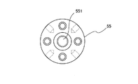
継手体55は図3に示すように円板体で、その板面中心には結合部551が突出形成されている。結合部551には外周にネジ溝が形成されて、このネジ溝をハブ部542内周のネジ溝内に進入させて継手体55が蓋体54に結合されている。継手体55にはこれと同径の厚肉円板状の先端体56(図4)が、ボルト552によって継手体55に結合されている。先端体56はテフロン(デュポン社登録商標)等のフッ素樹脂製で、これと同径の継手体55と一体に準備されて、後述する案内型61(図1)の内径に合わせて継手体55と共に適宜交換される。
As shown in FIG. 3, the
図1において、ベルトコンベアVCの搬送ベルトVC1の上面に接するようにこれを横切って下型6が配設されている。下型6はテフロン(デュポン社登録商標)等のフッ素樹脂製の厚肉の長尺板体で、その板面には長手方向へ図5に示すように上記ピストン部材5に対応させて複数(本実施形態では7つ)の案内型61が形成されている。各案内型61は円形の筒状に成形されており(図6)、その内径は、ピストン部材5の先端体56をその周囲に小間隙を成して受け入れる大きさとしてある。また、案内型61の上側開口は一方の周縁が外方へ緩い傾斜面をなすように切除されて、後述する菓子材料を受け入れるための受入れ面612となっている。
In FIG. 1, a
下型6内には案内型61の最奥端である下端開口611(図6)に接して成形型62が一体に形成されている。成形型62は本実施例では平面視で案内型61の外周に接する一定幅の周壁621に囲まれた正四角形の型空間を有し、周壁621の正四角の内周形状は成形される菓子製品(本実施形態ではせんべい)の外形とほぼ同一(例えば49mm角)としてある。また周壁621内周の高さ(型空間の深さ)は菓子製品の厚みとほぼ同一(例えば6mm)にしてある。このような下型6は、その一方の側縁に突設した取付片63に一定間隔で設けた取付穴631によって昇降ビーム71(図1)に取り付けられている。
A molding die 62 is integrally formed in the
昇降ビーム71は搬送ベルトVC1の上方を横切るように配設されており、その両端(図1に一方のみ示す)には昇降用駆動シリンダ72のロッド721の先端が結合されている。これにより、下型6はその成形型62が搬送ベルトVC1の上面に接した図1に示す位置から上方位置へ引き上げ可能である。なお、昇降ビーム71には長手方向へ間隔をおいて仕切板711が複数設けられて(図1)隣り合う案内型61の上側開口の間を仕切っている。
The elevating
このような構造の菓子成形機に対し、図7に示すように、上流側の材料供給コンベアVC2によって、米飯を蒸して略立方体形に成形された塊状の菓子材料CMが供給されると、これら菓子材料CMは各案内型61に対応して設けたシュートSHを経て案内型61内へ投入される。投入された菓子材料CMは、成形型62(図6)の下側開口に接してこれを閉鎖する搬送ベルトVC1の上面に落下して、成形型62および案内型61の型内に位置させられる。なお、菓子材料CNの容積は成形型62の内容積よりもやや大きい程度である。
As shown in FIG. 7, when the lump-shaped confectionery material CM formed by steaming cooked rice into a substantially cubic shape is supplied to the confectionery molding machine having such a structure, as shown in FIG. The confectionery material CM is put into the
この状態で、保持部材41が下降させられて、ピストン部材5が回転させられつつその先端体56が案内型61内へ下降進入させられると、先端体56が案内型61の下側開口へ至る間に菓子材料CMは成形型62内で徐々に押し拡げられ、先端体56が案内型61の下側開口に到達すると、菓子材料CMは正四角形状の成形型62内に満遍なく充満して成形型62の内空間に倣った扁平な正四角形に成形される。
In this state, when the holding
この際、いずれかの案内型61内に誤って2個の菓子材料CMが供給される等によって、当該案内型61内に進入した先端体56に過度の押圧力が印加された場合には、保持部材41が下降しても、バネ部材57が収縮変形して先端体56が後退し、無理な進入が防止される。そしてこの間、他のピストン部材5の先端体56は案内型61内に進入して菓子材料CMの成形が続行される。
At this time, when an excessive pressing force is applied to the
成形完了後には、ピストン部材5を上昇後退させ、さらに下型6を上昇させると、正四角形に成形された菓子製品のみが搬送ベルトVC1上に残るから、搬送ベルトVC1を移動させることによって菓子製品は後段の焼成機等に送られる。
After the molding is completed, when the
なお、上記実施形態において、成形型62の型形状は四角形に限られず、円形、三角形、あるいは各種異形の形状とすることができる。
In the above embodiment, the mold shape of the
21…駆動モータ(回転駆動機構)、22…駆動シリンダ、5…ピストン部材、51…シャフト部、52…ヘッド部、6…下型、61…案内型、62…成形型、CM…菓子材料。
DESCRIPTION OF
Claims (3)
Priority Applications (1)
| Application Number | Priority Date | Filing Date | Title |
|---|---|---|---|
| JP2011061813A JP2012196165A (en) | 2011-03-19 | 2011-03-19 | Confectionery molding machine |
Applications Claiming Priority (1)
| Application Number | Priority Date | Filing Date | Title |
|---|---|---|---|
| JP2011061813A JP2012196165A (en) | 2011-03-19 | 2011-03-19 | Confectionery molding machine |
Publications (1)
| Publication Number | Publication Date |
|---|---|
| JP2012196165A true JP2012196165A (en) | 2012-10-18 |
Family
ID=47179077
Family Applications (1)
| Application Number | Title | Priority Date | Filing Date |
|---|---|---|---|
| JP2011061813A Pending JP2012196165A (en) | 2011-03-19 | 2011-03-19 | Confectionery molding machine |
Country Status (1)
| Country | Link |
|---|---|
| JP (1) | JP2012196165A (en) |
Citations (11)
| Publication number | Priority date | Publication date | Assignee | Title |
|---|---|---|---|---|
| JPS5324069A (en) * | 1976-08-18 | 1978-03-06 | Okura Kikai Kk | Peeling apparatus for food material |
| JPS61282063A (en) * | 1985-06-10 | 1986-12-12 | Kibun Kk | Device for extrusion molding of food |
| JPH06339334A (en) * | 1993-06-01 | 1994-12-13 | Suehiro Ii P M:Kk | Forming of dough for food pastry shell and apparatus therefor |
| JPH07313041A (en) * | 1994-05-19 | 1995-12-05 | Takagi Denki Kogyo:Kk | Method for molding dough for japanese bun |
| JPH08191670A (en) * | 1995-01-13 | 1996-07-30 | Fuji Seiki Kk | Automatic supply device for ingredients such as food |
| JPH08308470A (en) * | 1995-05-12 | 1996-11-26 | Fuji Seisakusho:Kk | Production unit for piece-like article |
| JPH09322713A (en) * | 1996-06-06 | 1997-12-16 | Isao Kikuchi | Sweets molding machine |
| JP2001078652A (en) * | 1999-09-13 | 2001-03-27 | Kameda Seika Co Ltd | Rice cracker dough cutting machine |
| JP2006000154A (en) * | 2004-06-15 | 2006-01-05 | Ahjikan Co Ltd | Molded processed food manufacturing apparatus and molded processed food manufacturing method |
| JP2006087327A (en) * | 2004-09-22 | 2006-04-06 | Mukaihata Seisakusho:Kk | Noodle-making machine |
| JP2007274951A (en) * | 2006-04-05 | 2007-10-25 | Rheon Autom Mach Co Ltd | Method for rounding dough and apparatus |
-
2011
- 2011-03-19 JP JP2011061813A patent/JP2012196165A/en active Pending
Patent Citations (11)
| Publication number | Priority date | Publication date | Assignee | Title |
|---|---|---|---|---|
| JPS5324069A (en) * | 1976-08-18 | 1978-03-06 | Okura Kikai Kk | Peeling apparatus for food material |
| JPS61282063A (en) * | 1985-06-10 | 1986-12-12 | Kibun Kk | Device for extrusion molding of food |
| JPH06339334A (en) * | 1993-06-01 | 1994-12-13 | Suehiro Ii P M:Kk | Forming of dough for food pastry shell and apparatus therefor |
| JPH07313041A (en) * | 1994-05-19 | 1995-12-05 | Takagi Denki Kogyo:Kk | Method for molding dough for japanese bun |
| JPH08191670A (en) * | 1995-01-13 | 1996-07-30 | Fuji Seiki Kk | Automatic supply device for ingredients such as food |
| JPH08308470A (en) * | 1995-05-12 | 1996-11-26 | Fuji Seisakusho:Kk | Production unit for piece-like article |
| JPH09322713A (en) * | 1996-06-06 | 1997-12-16 | Isao Kikuchi | Sweets molding machine |
| JP2001078652A (en) * | 1999-09-13 | 2001-03-27 | Kameda Seika Co Ltd | Rice cracker dough cutting machine |
| JP2006000154A (en) * | 2004-06-15 | 2006-01-05 | Ahjikan Co Ltd | Molded processed food manufacturing apparatus and molded processed food manufacturing method |
| JP2006087327A (en) * | 2004-09-22 | 2006-04-06 | Mukaihata Seisakusho:Kk | Noodle-making machine |
| JP2007274951A (en) * | 2006-04-05 | 2007-10-25 | Rheon Autom Mach Co Ltd | Method for rounding dough and apparatus |
Similar Documents
| Publication | Publication Date | Title |
|---|---|---|
| US10681916B2 (en) | Device for forming a sheeted dough from a dough piece by pressing | |
| CN105996092B (en) | A kind of tablet press machine | |
| CN209768761U (en) | Shaomai forming equipment | |
| EP3384776B1 (en) | Device for forming pieces of dough to form dough products | |
| CN107821511A (en) | A kind of blank formula send mould custard tart machine automatically | |
| JP3811789B2 (en) | Food dough shaping device | |
| KR101554893B1 (en) | Production device and production method for layered food | |
| JPH03108471A (en) | Meat patty forming machine | |
| CN108812827B (en) | Initial processing device is used in production of characteristic tradition snack | |
| CN204697808U (en) | Skin forming mechanism for pastry food | |
| CN108402119B (en) | A rotary processing and forming device for steamed buns | |
| JP2012196165A (en) | Confectionery molding machine | |
| KR101241536B1 (en) | Apparatus for manufacturing dumpling | |
| JP6208037B2 (en) | Molded plate | |
| CA2903801C (en) | Cutter having varied cavity draft angle | |
| JP2014082950A (en) | Rice molding mechanism and rice molding method | |
| CN203087401U (en) | Cone processing and baking device | |
| JP5785719B2 (en) | Cooked rice molding equipment | |
| CN219288588U (en) | Full-automatic egg tart skin make-up machine equipment | |
| JP5796884B2 (en) | Cooked rice forming equipment | |
| CN117941720A (en) | Forming system and method for dried vegetable thin pancake | |
| CN207497661U (en) | One kind send mould custard tart machine automatically | |
| CN212589979U (en) | Egg tart automatic forming machine | |
| CN205667319U (en) | A kind of fried gluten puff base ball automatic processing device | |
| CN204335658U (en) | A kind ofly be applicable to the shaping flow-line equipment of the automatic cake of press of hand grasping pie |
Legal Events
| Date | Code | Title | Description |
|---|---|---|---|
| A621 | Written request for application examination |
Free format text: JAPANESE INTERMEDIATE CODE: A621 Effective date: 20140312 |
|
| A977 | Report on retrieval |
Free format text: JAPANESE INTERMEDIATE CODE: A971007 Effective date: 20150224 |
|
| A131 | Notification of reasons for refusal |
Free format text: JAPANESE INTERMEDIATE CODE: A131 Effective date: 20150323 |
|
| A02 | Decision of refusal |
Free format text: JAPANESE INTERMEDIATE CODE: A02 Effective date: 20150722 |