JP2012196611A - Flue gas desulfurization apparatus and flue gas desulfurization method - Google Patents
Flue gas desulfurization apparatus and flue gas desulfurization method Download PDFInfo
- Publication number
- JP2012196611A JP2012196611A JP2011061259A JP2011061259A JP2012196611A JP 2012196611 A JP2012196611 A JP 2012196611A JP 2011061259 A JP2011061259 A JP 2011061259A JP 2011061259 A JP2011061259 A JP 2011061259A JP 2012196611 A JP2012196611 A JP 2012196611A
- Authority
- JP
- Japan
- Prior art keywords
- water
- absorption tower
- flue gas
- seawater
- exhaust gas
- Prior art date
- Legal status (The legal status is an assumption and is not a legal conclusion. Google has not performed a legal analysis and makes no representation as to the accuracy of the status listed.)
- Pending
Links
- UGFAIRIUMAVXCW-UHFFFAOYSA-N Carbon monoxide Chemical compound [O+]#[C-] UGFAIRIUMAVXCW-UHFFFAOYSA-N 0.000 title claims abstract description 91
- 239000003546 flue gas Substances 0.000 title claims abstract description 91
- 238000006477 desulfuration reaction Methods 0.000 title claims abstract description 90
- 230000023556 desulfurization Effects 0.000 title claims abstract description 90
- 238000000034 method Methods 0.000 title claims description 11
- 238000010521 absorption reaction Methods 0.000 claims abstract description 168
- XLYOFNOQVPJJNP-UHFFFAOYSA-N water Substances O XLYOFNOQVPJJNP-UHFFFAOYSA-N 0.000 claims abstract description 138
- 239000003595 mist Substances 0.000 claims abstract description 113
- 239000013535 sea water Substances 0.000 claims abstract description 87
- 239000007788 liquid Substances 0.000 claims abstract description 76
- 238000005406 washing Methods 0.000 claims abstract description 40
- 238000011144 upstream manufacturing Methods 0.000 claims abstract description 29
- XTQHKBHJIVJGKJ-UHFFFAOYSA-N sulfur monoxide Chemical class S=O XTQHKBHJIVJGKJ-UHFFFAOYSA-N 0.000 claims abstract description 20
- 238000002485 combustion reaction Methods 0.000 claims abstract description 11
- 229910052815 sulfur oxide Inorganic materials 0.000 claims abstract description 11
- 239000007789 gas Substances 0.000 claims description 194
- 230000001590 oxidative effect Effects 0.000 claims description 45
- 239000002826 coolant Substances 0.000 claims description 36
- 238000007254 oxidation reaction Methods 0.000 claims description 17
- 230000003647 oxidation Effects 0.000 claims description 15
- 238000011010 flushing procedure Methods 0.000 claims description 4
- 238000005507 spraying Methods 0.000 claims description 3
- 239000010440 gypsum Substances 0.000 description 22
- 229910052602 gypsum Inorganic materials 0.000 description 22
- 239000007787 solid Substances 0.000 description 15
- 239000007921 spray Substances 0.000 description 15
- 239000002002 slurry Substances 0.000 description 13
- 239000002250 absorbent Substances 0.000 description 12
- 230000002745 absorbent Effects 0.000 description 12
- 239000008235 industrial water Substances 0.000 description 11
- 239000002351 wastewater Substances 0.000 description 10
- TXKMVPPZCYKFAC-UHFFFAOYSA-N disulfur monoxide Inorganic materials O=S=S TXKMVPPZCYKFAC-UHFFFAOYSA-N 0.000 description 9
- 239000013505 freshwater Substances 0.000 description 9
- 239000000706 filtrate Substances 0.000 description 8
- ZAMOUSCENKQFHK-UHFFFAOYSA-N Chlorine atom Chemical compound [Cl] ZAMOUSCENKQFHK-UHFFFAOYSA-N 0.000 description 7
- 239000000460 chlorine Substances 0.000 description 7
- 229910052801 chlorine Inorganic materials 0.000 description 7
- 230000000694 effects Effects 0.000 description 7
- 235000019738 Limestone Nutrition 0.000 description 6
- 239000006028 limestone Substances 0.000 description 6
- 238000010248 power generation Methods 0.000 description 6
- 239000000498 cooling water Substances 0.000 description 5
- 238000000605 extraction Methods 0.000 description 5
- 238000004065 wastewater treatment Methods 0.000 description 5
- KRHYYFGTRYWZRS-UHFFFAOYSA-N Fluorane Chemical compound F KRHYYFGTRYWZRS-UHFFFAOYSA-N 0.000 description 4
- VEXZGXHMUGYJMC-UHFFFAOYSA-N Hydrochloric acid Chemical compound Cl VEXZGXHMUGYJMC-UHFFFAOYSA-N 0.000 description 4
- RAHZWNYVWXNFOC-UHFFFAOYSA-N Sulphur dioxide Chemical compound O=S=O RAHZWNYVWXNFOC-UHFFFAOYSA-N 0.000 description 4
- 230000002378 acidificating effect Effects 0.000 description 4
- GBAOBIBJACZTNA-UHFFFAOYSA-L calcium sulfite Chemical compound [Ca+2].[O-]S([O-])=O GBAOBIBJACZTNA-UHFFFAOYSA-L 0.000 description 4
- 235000010261 calcium sulphite Nutrition 0.000 description 4
- 238000001816 cooling Methods 0.000 description 4
- 230000007423 decrease Effects 0.000 description 4
- 229910000040 hydrogen fluoride Inorganic materials 0.000 description 4
- 239000000428 dust Substances 0.000 description 3
- 239000003507 refrigerant Substances 0.000 description 3
- 150000003839 salts Chemical class 0.000 description 3
- 235000008733 Citrus aurantifolia Nutrition 0.000 description 2
- 235000011941 Tilia x europaea Nutrition 0.000 description 2
- LVGQIQHJMRUCRM-UHFFFAOYSA-L calcium bisulfite Chemical compound [Ca+2].OS([O-])=O.OS([O-])=O LVGQIQHJMRUCRM-UHFFFAOYSA-L 0.000 description 2
- 229940043430 calcium compound Drugs 0.000 description 2
- 150000001674 calcium compounds Chemical class 0.000 description 2
- 235000010260 calcium hydrogen sulphite Nutrition 0.000 description 2
- 239000007795 chemical reaction product Substances 0.000 description 2
- -1 chlorine Chemical class 0.000 description 2
- 238000010586 diagram Methods 0.000 description 2
- 238000001035 drying Methods 0.000 description 2
- IXCSERBJSXMMFS-UHFFFAOYSA-N hydrogen chloride Substances Cl.Cl IXCSERBJSXMMFS-UHFFFAOYSA-N 0.000 description 2
- 229910000041 hydrogen chloride Inorganic materials 0.000 description 2
- 238000009434 installation Methods 0.000 description 2
- 239000013067 intermediate product Substances 0.000 description 2
- 239000004571 lime Substances 0.000 description 2
- 239000000203 mixture Substances 0.000 description 2
- 229920006395 saturated elastomer Polymers 0.000 description 2
- 239000004071 soot Substances 0.000 description 2
- 238000003756 stirring Methods 0.000 description 2
- 239000000126 substance Substances 0.000 description 2
- 239000002912 waste gas Substances 0.000 description 2
- 238000009736 wetting Methods 0.000 description 2
- NINIDFKCEFEMDL-UHFFFAOYSA-N Sulfur Chemical compound [S] NINIDFKCEFEMDL-UHFFFAOYSA-N 0.000 description 1
- 238000003915 air pollution Methods 0.000 description 1
- 239000003795 chemical substances by application Substances 0.000 description 1
- 230000007797 corrosion Effects 0.000 description 1
- 238000005260 corrosion Methods 0.000 description 1
- 230000018044 dehydration Effects 0.000 description 1
- 238000006297 dehydration reaction Methods 0.000 description 1
- 230000006866 deterioration Effects 0.000 description 1
- 238000005516 engineering process Methods 0.000 description 1
- 238000001704 evaporation Methods 0.000 description 1
- 239000000446 fuel Substances 0.000 description 1
- 238000011084 recovery Methods 0.000 description 1
- 239000008237 rinsing water Substances 0.000 description 1
- 239000011593 sulfur Substances 0.000 description 1
- 229910052717 sulfur Inorganic materials 0.000 description 1
Images


Landscapes
- Gas Separation By Absorption (AREA)
- Chimneys And Flues (AREA)
- Treating Waste Gases (AREA)
Abstract
Description
本発明は、火力発電所や工場等に設置されるボイラ等の燃焼設備から排出される、排ガスを浄化するための排煙処理装置に係り、特に、ボイラ等の燃焼排ガス中に含まれる硫黄酸化物、塩化水素、フッ化水素等の酸性ガスやばいじん、及び燃料中に含まれる微量成分等の人的にも有害な物質を低減する排煙脱硫装置及び排煙脱硫方法に関する。 The present invention relates to a flue gas treatment apparatus for purifying exhaust gas discharged from combustion equipment such as a boiler installed in a thermal power plant or factory, and in particular, sulfur oxidation contained in combustion exhaust gas such as a boiler. The present invention relates to a flue gas desulfurization apparatus and a flue gas desulfurization method that reduce harmful substances such as substances, hydrogen chloride, hydrogen fluoride and other acidic gases and dust, and trace components contained in fuel.
大気汚染防止のため、排ガス中の硫黄酸化物の除去装置として、湿式石灰石−石膏法排煙脱硫装置が広く実用化されている。火力発電設備における湿式排煙脱硫装置の一般的な系統を図6に示す。なお、各図において同一機器(装置)には同一番号を付している。 In order to prevent air pollution, wet limestone-gypsum flue gas desulfurization devices have been widely put into practical use as devices for removing sulfur oxides in exhaust gas. FIG. 6 shows a general system of a wet type flue gas desulfurization apparatus in a thermal power generation facility. In addition, the same number is attached | subjected to the same apparatus (apparatus) in each figure.
火力発電所や工場等に設置されるボイラ等の燃焼装置から排出される硫黄酸化物を含む排ガスは矢印A方向から吸収塔4の入り口煙道1に設置されたガスガスヒータ(熱交換器)20を通り排ガスの熱が回収され、ガス温度は90〜110℃に低下する。ガス温度が一定値以下に低下した排ガスは、ガス入口部3から湿式排煙脱硫装置の吸収塔4へと導入される。
An exhaust gas containing sulfur oxides discharged from a combustion apparatus such as a boiler installed in a thermal power plant or factory is a gas gas heater (heat exchanger) 20 installed in the
吸収塔4は液溜部5と吸収部(スプレ部)6から構成され、吸収部6では、排ガスの流れ方向に沿って上下に複数段の多数のスプレノズル9を備えたスプレヘッダ8が設置されており、スプレノズル9から微細な液滴として噴霧される石灰石または石灰を含むスラリなどの吸収剤の液滴と排ガスとを接触させることで、排ガス中のばいじんや塩化水素(HCl)、フッ化水素(HF)等の酸性ガスと共に、排ガス中の硫黄酸化物(SOx)はスプレノズル9の吸収液滴表面で化学的に吸収、除去される。
The absorption tower 4 is composed of a
液溜部5には、ボイラ等からの排ガスに含まれる硫黄酸化物の量に応じて、吸収剤スラリ(主に石灰石スラリ)供給ライン16から吸収剤が供給される。液溜部5にあるスラリ状の吸収液は、吸収液循環ポンプ10により昇圧され、吸収液循環配管13を経由して、吸収塔4内の上部の吸収部6のスプレヘッダ8に供給される。
The
また、排ガスの流れに同伴する微小な液滴(ミスト)は吸収塔4の上部のガス出口部18に設置されたミストエリミネータ7により除去される。ミストエリミネータ7を通過した排ガス温度は、通常、50℃程度の水分飽和ガスであるが、ミストエリミネータ7の排ガス流路下流に設置されるガスガスヒータ20を通過することで再加熱される。すなわちミストエリミネータ7を通過した排ガスは、ガスガスヒータ20において回収された吸収塔4の入口ガスの熱によってガス温度が約90〜100℃程度まで再加熱され、出口煙道2から矢印B方向に流れ、最終的に煙突(図示せず)に導入された後、大気中に排出される。
Further, minute droplets (mist) accompanying the flow of the exhaust gas are removed by the mist eliminator 7 installed at the
吸収塔4の出口に設置されたミストエリミネータ7には、吸収塔4を循環する吸収液が飛散し、ミストエリミネータ7のエレメントに付着するため、水洗装置31を設けている。この水洗装置31の水洗水として工業用水を用いてエレメントの水洗を行っている。
The mist eliminator 7 installed at the outlet of the absorption tower 4 is provided with a
ボイラ等から排出される排ガス中に含まれる二酸化硫黄(SO2)などの硫黄酸化物は、吸収液中に含まれるカルシウム化合物(石灰石(CaCO3)など)と反応し、中間生成物として亜硫酸カルシウム(重亜硫酸カルシウムを含む)になり、液溜部5に流下する。一方、液溜部5には、酸化用空気ブロワ17により酸化用空気供給ライン26から酸化用空気を強制的に供給し、該酸化用空気と亜硫酸カルシウムとの酸化反応により、反応生成物として石膏スラリ(CaSO4・2H2O)となる。
Sulfur oxides such as sulfur dioxide (SO 2 ) contained in exhaust gas discharged from boilers react with calcium compounds (limestone (CaCO 3 ), etc.) contained in the absorption liquid, and calcium sulfite as an intermediate product (Including calcium bisulfite) and flows down to the
なお、その際に液溜部5に供給する酸化用空気は、液溜部5内の吸収液を攪拌する酸化用攪拌機15により微細化されることにより、酸化用空気の利用率を高めている。液溜部5内の吸収液は概ね50℃程度であるが、酸化用空気ブロワ17出口の空気温度は、通常、120〜150℃であり、そのまま液溜部5に供給すると液溜部5の吸収液中に内挿した配管端部で乾湿の繰り返しが生じるため、酸化用空気ブロワ17出口の空気は、工業用水を直接噴霧することにより空気温度を水分飽和温度まで低下させ、液溜部5に供給される。
In this case, the oxidizing air supplied to the
液溜部5内の吸収液スラリは、吸収塔抜出しポンプ11により、生成石膏量に応じて液溜部5から石膏脱水設備12に抜き出されて脱水され、石膏14は回収される。一方、ろ液はろ液回収タンク21に貯留され、ろ液ポンプ22によって抜き出され、排水ライン23から湿式排煙脱硫装置の系外に排出される。
The absorbent slurry in the
また、湿式排煙脱硫装置の設備全体の水量バランスを維持するための補給水は、吸収塔4の液溜部供給ライン35とミストエリミネータ7の水洗水供給ライン37から供給される。
In addition, makeup water for maintaining the balance of the amount of water in the entire equipment of the wet flue gas desulfurization apparatus is supplied from a liquid
特に火力発電所等で使用する用水量の確保が困難な地域では、湿式排煙脱硫装置に使用する補給水量の低減が必要不可欠となっている。そして、湿式排煙脱硫装置における新水(工業用水)の使用量を節減するために、除塵塔と吸収塔との間に設置されたミストエリミネータの水洗水として、ガス流れ下流側(吸収塔側)のミストエリミネータの洗浄には新水を使用する一方、ガス流れ上流側(除塵塔側)のミストエリミネータの洗浄にはミストエリミネータの洗浄排水を循環使用する構成(下記特許文献1)が提案されている。 Particularly in areas where it is difficult to secure the amount of water used in thermal power plants, etc., it is essential to reduce the amount of makeup water used in wet flue gas desulfurization equipment. In order to reduce the amount of new water (industrial water) used in the wet flue gas desulfurization system, the water flow downstream side (absorption tower side) is used as flush water for the mist eliminator installed between the dust removal tower and the absorption tower. ) Is used to clean the mist eliminator, while the mist eliminator on the upstream side (dust removal tower side) of the mist eliminator is used to clean the mist eliminator. ing.
また、下記特許文献2には、脱硫前の排ガスに冷却液を循環冷却液噴霧器により直接噴霧して増湿冷却した後、排ガスを熱交換器により冷却液と間接接触させて冷却し、その後吸収剤スラリーによって排ガスを洗浄する構成が開示されている。排ガス流路の上流側に循環冷却液噴霧器を設け、下流側に熱交換器を設けることで、熱交換器外側を常に湿潤状態にして水分損失量を削減し、湿式排煙脱硫装置に使用する補給水量を削減している。
In
更に、下記特許文献3に記載の構成では、横長のコンパクトな吸収部の前に横長のコンパクトなガス調湿部を設けて、このガス調湿部でボイラからの排水や海水を冷却水として用いることで、補給水量を節減している。
Furthermore, in the configuration described in
上述の従来技術において、ボイラ等を定格運用負荷帯(高負荷帯)で運用する場合には、ガスガスヒータにより排ガスの熱が回収された後においても、吸収塔の入口ガス温度は90〜110℃と比較的高温である。したがって、吸収塔内における蒸発水量が多くなり、液溜部の液面高さ(液レベル)や吸収液スラリの濃度を一定に維持し、湿式排煙脱硫装置の設備全体の水量バランスを維持するためには、吸収塔に多量の補給水が必要になるという問題がある。 In the above-described prior art, when a boiler or the like is operated in a rated operation load zone (high load zone), the inlet gas temperature of the absorption tower is 90 to 110 ° C. even after the heat of the exhaust gas is recovered by the gas gas heater. And relatively hot. Therefore, the amount of evaporated water in the absorption tower increases, the liquid level in the liquid reservoir (liquid level) and the concentration of the absorbent slurry are kept constant, and the water amount balance of the entire wet flue gas desulfurization equipment is maintained. Therefore, there is a problem that a large amount of makeup water is required in the absorption tower.
この対策として、吸収塔の入口に設置したガスガスヒータの容量を従来よりも大きなものとし、吸収塔の入口の排ガス温度を下げることにより、吸収塔における蒸発水量は低減でき、湿式排煙脱硫装置の設備全体として必要となる補給水量も低減可能となる。 As a countermeasure, the capacity of the gas gas heater installed at the entrance of the absorption tower is made larger than before, and the amount of evaporated water in the absorption tower can be reduced by lowering the exhaust gas temperature at the entrance of the absorption tower. The amount of makeup water required for the entire facility can also be reduced.
しかし、ガスガスヒータの容量を大きくすると、火力発電設備の運用状態により、ボイラ等を低負荷帯で運用した場合には、吸収塔内における蒸発水量が少なくなり、逆に、湿式排煙脱硫装置の設備全体の水量バランスを維持することが困難になる。すなわち、ミストエリミネータの水洗排水、及び吸収塔の酸化用空気増湿水が吸収塔へ供給されることにより、吸収塔に供給される水量が吸収塔から抜き出される水量に対して過剰となり、湿式排煙脱硫装置の設備全体の水量バランスが維持できなくなるといった問題が挙げられる。 However, when the capacity of the gas gas heater is increased, the amount of evaporated water in the absorption tower is reduced when the boiler is operated in a low load zone due to the operating state of the thermal power generation facility. It becomes difficult to maintain the water volume balance of the entire facility. That is, by supplying the washing water of the mist eliminator and the air humidified water for oxidation of the absorption tower to the absorption tower, the amount of water supplied to the absorption tower becomes excessive with respect to the amount of water extracted from the absorption tower. There is a problem that it becomes impossible to maintain the water balance of the entire equipment of the flue gas desulfurization apparatus.
一方、特許文献1に記載の構成のように、ミストエリミネータの洗浄排水を循環使用したり、特許文献2に記載の構成のように、熱交換器外側を常に湿潤状態にして水分損失量を削減したり、特許文献3に記載の構成のように、吸収部やガス調湿部をコンパクトな構成としてガス調湿部でボイラからの排水や海水を冷却水として用いることで、ある程度の補給水量の低減は可能となる。
On the other hand, the waste water from the mist eliminator is circulated and used as in the configuration described in
しかし、特許文献1に記載の構成では、ガス流れ下流側のミストエリミネータの水洗水には新水を使用しているため、新水の使用量の節減は未だ不十分であると言える。
However, in the configuration described in
また、特許文献2に記載の構成では、石膏等の固形物を含む吸収液を熱交換器の上流で噴霧し、熱交換器外側を常に湿潤にしているが、ガス温度は比較的高温であることから、部分的(局部的)には乾湿の繰り返しの箇所が生じ、設備の腐食が著しくなる他、吸収液中の固形物による詰まり、付着により経時的な性能低下が問題となる。
Further, in the configuration described in
また、特許文献3に記載の構成では、ガス調節部、吸収部を横長の構成とし、水平方向に設置することにより、高さ方向には低い設備になるが、逆に設備の設置面積は大きくなるといった問題がある。
Further, in the configuration described in
そして、特許文献2及び特許文献3に記載の構成では、ある程度節水効果は期待されるものの、ミストエリミネータの水洗水などの比較的多量に水を使用する設備に関しては何ら考慮されていない。
In the configurations described in
本発明の課題は、脱硫性能は現状と同程度に維持したまま、且つ低コストで排煙脱硫装置における補給水量を低減可能な節水及び省水型の排煙脱硫装置及び排煙脱硫方法を提供することである。 An object of the present invention is to provide a water-saving and water-saving type flue gas desulfurization apparatus and a flue gas desulfurization method that can reduce the amount of makeup water in the flue gas desulfurization apparatus at a low cost while maintaining the desulfurization performance at the same level as the current situation. It is to be.
上記本発明の課題は、下記の構成を採用することにより達成できる。
請求項1記載の発明は、ボイラを含む燃焼装置から排出される排ガスを導入し、該排ガスに吸収液を噴霧して気液接触させることにより、前記排ガス中に含まれる硫黄酸化物を吸収、除去する吸収塔と、該吸収塔の排ガス流路の出口に設けられ、吸収塔から放出されるミストを捕集するミストエリミネータと、該ミストエリミネータを水洗するミストエリミネータ水洗装置とを設けた排煙脱硫装置において、前記ミストエリミネータを排ガス流路の上流側と下流側に複数設け、前記ミストエリミネータ水洗装置に前記各ミストエリミネータに水洗用の水を供給する水洗水供給部を設け、前記下流側のミストエリミネータの水洗水供給部に海水を供給する海水供給部を設けた排煙脱硫装置である。
The object of the present invention can be achieved by adopting the following constitution.
The invention according to
請求項2記載の発明は、前記吸収塔の排ガス流路の入口に、内部に冷却媒体用の管を有する排ガス冷却器を設け、前記冷却媒体用の管に海水を供給する海水供給部を設けた請求項1記載の排煙脱硫装置である。
According to a second aspect of the present invention, an exhaust gas cooler having a cooling medium pipe inside is provided at an inlet of the exhaust gas flow path of the absorption tower, and a seawater supply unit for supplying seawater to the cooling medium pipe is provided. The flue gas desulfurization apparatus according to
請求項3記載の発明は、前記吸収塔に酸化用空気を供給する酸化用空気供給部を設け、該酸化用空気供給部に、内部に冷却媒体用の管を有する酸化用空気冷却器を設け、前記冷却媒体用の管に海水を供給する海水供給部を設けた請求項1記載の排煙脱硫装置である。
According to a third aspect of the present invention, an oxidation air supply section for supplying oxidation air to the absorption tower is provided, and an oxidation air cooler having a cooling medium pipe inside is provided in the oxidation air supply section. The flue gas desulfurization apparatus according to
請求項4記載の発明は、ボイラを含む燃焼装置から排出される排ガスを吸収塔に導入して吸収液を噴霧し、排ガスと気液接触させることにより、前記排ガス中に含まれる硫黄酸化物を吸収、除去した後、前記吸収塔から放出されるミストを吸収塔の排ガス流路の出口の上流側と下流側に複数設けたミストエリミネータにより捕集して、該ミストを捕集したミストエリミネータを水洗する排煙脱硫方法であって、前記下流側のミストエリミネータの水洗水に海水を使用する排煙脱硫方法である。 The invention according to claim 4 introduces the exhaust gas discharged from the combustion device including the boiler into the absorption tower, sprays the absorbing liquid, and makes the sulfur oxide contained in the exhaust gas come into gas-liquid contact with the exhaust gas. After absorption and removal, the mist discharged from the absorption tower is collected by a plurality of mist eliminators provided upstream and downstream of the outlet of the exhaust gas passage of the absorption tower, and the mist eliminator that has collected the mist is collected. A flue gas desulfurization method for washing with water, wherein sea water is used as flush water for the downstream mist eliminator.
請求項5記載の発明は、海水を冷却媒体に使用して前記吸収塔入口の排ガスを冷却する請求項4記載の排煙脱硫方法である。
請求項6記載の発明は、前記吸収塔に酸化用空気を供給すると共に、海水を冷却媒体に使用して前記吸収塔に供給する酸化用空気を冷却することを特徴とする請求項4記載の排煙脱硫方法である。
The invention according to
The invention according to claim 6 supplies the oxidizing air to the absorption tower and cools the oxidizing air supplied to the absorption tower using seawater as a cooling medium. It is a flue gas desulfurization method.
(作用)
上記課題は、吸収塔の出口に設置されたミストエリミネータの水洗水量の低減、排煙脱硫装置の吸収塔内における蒸発水量の低減、及び吸収塔の液溜部に供給する酸化用空気の増湿水量の低減によって解決できる。
(Function)
The above issues are the reduction of the amount of water washed by the mist eliminator installed at the outlet of the absorption tower, the reduction of the amount of evaporated water in the absorption tower of the flue gas desulfurization device, and the increase of the humidity of the oxidizing air supplied to the liquid reservoir of the absorption tower This can be solved by reducing the amount of water.
上述のように、例えば、吸収塔の入口に設置したガスガスヒータの容量を従来よりも大きなものとし、吸収塔の入口の排ガス温度を下げた場合、火力発電設備の運用状態により、ボイラ等を低負荷帯で運用する条件では、排煙脱硫装置の設備全体の水量バランスを維持することが困難になるといった問題があった。 As described above, for example, when the capacity of the gas gas heater installed at the inlet of the absorption tower is made larger than before, and the exhaust gas temperature at the inlet of the absorption tower is lowered, the boiler and the like are reduced depending on the operating state of the thermal power generation facility. Under the condition of operating in the load zone, there is a problem that it becomes difficult to maintain the water volume balance of the entire facility of the flue gas desulfurization apparatus.
吸収塔の出口に設置されたミストエリミネータには、吸収塔を循環する吸収液が飛散し、ミストエリミネータのエレメントに付着する付着物も多い。そして、ミストエリミネータの水洗排水には多量の石膏等の固形物を含んでいる。したがって、水洗排水は一旦吸収塔に戻して補給水として再利用し、且つ固形物は石膏抜き出しラインより排出して回収する必要がある。 In the mist eliminator installed at the outlet of the absorption tower, the absorption liquid circulating through the absorption tower scatters and there are many deposits attached to the elements of the mist eliminator. And the washing drainage of the mist eliminator contains a large amount of solids such as gypsum. Therefore, it is necessary to return the washing waste water to the absorption tower and reuse it as make-up water, and to discharge and collect the solid matter from the gypsum extraction line.
上記特許文献2に記載の構成では、熱交換器の冷媒として海水を使用したり、特許文献3に記載の構成では、ガス調湿部のダクト部を通過する排ガスを冷却する冷却水に海水を使用したりすることで、排煙脱硫装置における補給水量を低減している。
In the configuration described in
海水中には塩素等の溶解塩が多量に含まれていることから、海水は吸収塔の補給水には利用されておらず、熱交換器の冷媒や排ガスを冷却する冷却水として使用された海水は冷媒等に循環使用されたり、そのまま排煙脱硫装置の系外に排出される。 Since seawater contains a large amount of dissolved salts such as chlorine, seawater is not used as the make-up water for the absorption tower, but was used as cooling water for cooling the heat exchanger refrigerant and exhaust gas. Seawater is circulated and used as a refrigerant, or is directly discharged out of the flue gas desulfurization system.
上述のように、ミストエリミネータの水洗排水には多量の石膏等の固形物を含んでいるため、水洗排水を回収して吸収液として再利用したり、石膏等を回収する必要がある。したがって、ミストエリミネータの水洗排水には海水は不向きであり利用されていなかった。 As described above, since the washing drainage of the mist eliminator contains a large amount of solids such as gypsum, it is necessary to collect the washing drainage and reuse it as an absorbent, or collect gypsum and the like. Therefore, seawater was unsuitable and not used for flushing drainage of the mist eliminator.
しかし、本発明者らは、ミストエリミネータを排ガス流路の上流側と下流側に複数設け、下流側のミストエリミネータの水洗水にのみ海水を使用することで、排煙脱硫装置の設備全体に供給される新水の使用量を大幅に低減できることを見出し、本発明を完成させた。 However, the present inventors provide a plurality of mist eliminators on the upstream side and downstream side of the exhaust gas flow path, and use seawater only for washing water of the downstream mist eliminator, thereby supplying the entire equipment of the flue gas desulfurization apparatus. The present invention has been completed by finding that the amount of fresh water used can be greatly reduced.
すなわち、請求項1又は請求項4記載の発明によれば、吸収塔から放出されるミストを捕集するミストエリミネータを排ガス流路の上流側と下流側に複数設け、ミストエリミネータ水洗装置に各ミストエリミネータに水洗用の水を供給する水洗水供給部を設け、下流側のミストエリミネータの水洗水供給部に海水を供給する海水供給部を設けることで、下流側のミストエリミネータの水洗水には海水を使用することにより、排煙脱硫装置の設備全体に供給される新水(工業用水)の使用量を低減できる。 That is, according to the first or fourth aspect of the present invention, a plurality of mist eliminators for collecting the mist discharged from the absorption tower are provided on the upstream side and the downstream side of the exhaust gas flow path, and each mist eliminator water washing device has each mist eliminator. A flush water supply unit that supplies flush water to the eliminator and a sea water supply unit that supplies sea water to the flush water supply unit of the downstream mist eliminator are provided. By using this, the amount of new water (industrial water) supplied to the entire equipment of the flue gas desulfurization apparatus can be reduced.
排ガス流路の上流側のミストエリミネータには、吸収塔から多量の吸収液が飛散するため、ミストエリミネータへの付着物も多くなり、その水洗排水には多量の石膏等の固形物を含んでいる。したがって、排ガス流路の上流側のミストエリミネータの水洗排水は一旦吸収塔に戻し、水洗排水は吸収塔の補給水として再利用し、且つ、固形物は吸収塔から抜き出して石膏を回収すれば良い。 The mist eliminator on the upstream side of the exhaust gas flow channel has a large amount of absorbing liquid scattered from the absorption tower, so that the amount of deposits on the mist eliminator increases, and the washing waste water contains a large amount of solids such as gypsum. . Therefore, it is only necessary to return the washing effluent of the mist eliminator upstream of the exhaust gas passage to the absorption tower, reuse the washing effluent as make-up water for the absorption tower, and extract the solid matter from the absorption tower to collect the gypsum. .
排ガス流路の上流側のミストエリミネータの水洗水にも海水を使用した場合、海水中には塩素等の溶解塩が多量に含まれていることから、水洗排水を吸収塔に戻すと、吸収塔内を循環する吸収液中の塩素濃度が高くなる。一般に、吸収液中の塩素濃度が高くなると吸収液のpHが低下して脱硫性能は低下する。また、ミストエリミネータの水洗排水を排煙脱硫装置の系外に排出する場合には、多量の固形物を含むため、排水処理設備が必要となる。 When seawater is also used for the washing water of the mist eliminator upstream of the exhaust gas flow path, the seawater contains a large amount of dissolved salts such as chlorine, so if the washing wastewater is returned to the absorption tower, the absorption tower The chlorine concentration in the absorption liquid circulating inside increases. Generally, when the chlorine concentration in the absorbing solution increases, the pH of the absorbing solution decreases and the desulfurization performance decreases. In addition, when draining the waste water from the mist eliminator to the outside of the flue gas desulfurization system, a large amount of solid matter is contained, and thus a waste water treatment facility is required.
本発明によれば、排ガス流路の上流側のミストエリミネータは新水(工業用水)を用いて洗浄し、排ガス流路の下流側のミストエリミネータは海水を用いて洗浄することを特徴としている。吸収塔から飛散する固形物の多くは排ガス流路の上流側のミストエリミネータにおいて捕集されており、下流側のミストエリミネータへの固形物の付着量は少ない。したがって、排ガス流路の下流側のミストエリミネータの水洗排水(海水)は排煙脱硫装置の系外にそのまま排出すれば良いため、排水処理設備を必要とせず、又は排水処理設備の簡素化が可能となる。 According to the present invention, the mist eliminator on the upstream side of the exhaust gas passage is washed with fresh water (industrial water), and the mist eliminator on the downstream side of the exhaust gas passage is washed with seawater. Most of the solid matter scattered from the absorption tower is collected by the mist eliminator on the upstream side of the exhaust gas flow path, and the amount of solid matter attached to the mist eliminator on the downstream side is small. Therefore, the flush water (seawater) of the mist eliminator on the downstream side of the exhaust gas flow path may be discharged as it is outside the system of the flue gas desulfurization device, so that no waste water treatment equipment is required or the waste water treatment equipment can be simplified. It becomes.
このように、排ガス流路の下流側のミストエリミネータは海水を用いて洗浄することで、吸収塔へ供給する水量は低減し、ボイラ等の運転状態や運転負荷に関わらず、排煙脱硫装置の設備全体の水量バランスを維持したままボイラ等の安定運用が可能となる。そして、排煙脱硫装置の設備全体として必要となる補給水量も低減することが可能となる。 In this way, the mist eliminator on the downstream side of the exhaust gas flow path is washed with seawater, so that the amount of water supplied to the absorption tower is reduced, and the flue gas desulfurization device is independent of the operating state and operating load of the boiler and the like. Boilers can be stably operated while maintaining the water balance of the entire facility. And it becomes possible to reduce the amount of makeup water required as the whole equipment of the flue gas desulfurization apparatus.
また、請求項2又は請求項5記載の発明によれば、上記請求項1又は請求項4記載の発明の作用に加えて、吸収塔の排ガス流路の入口にガス冷却器を設けることにより、吸収塔の入口のガス温度が低下するため、吸収塔内を循環している吸収液の蒸発水量は低減し、排煙脱硫装置の設備全体の水量バランスを維持するために必要な補給水量の大幅な節減が図れる。
According to the invention of
そして、海水をガス冷却器の冷却媒体に使用することで新水の更なる低減が図れると共に、ガス冷却器への冷却水(海水)量を制御することにより、吸収塔の入口ガス温度を所定値に維持できる。すなわち、排煙脱硫装置の設備全体の水量バランスを維持可能な温度に維持できる。 Further, by using seawater as a cooling medium for the gas cooler, new water can be further reduced, and by controlling the amount of cooling water (seawater) to the gas cooler, the inlet gas temperature of the absorption tower is predetermined. Value can be maintained. That is, it is possible to maintain the water amount balance of the entire equipment of the flue gas desulfurization apparatus at a temperature at which it can be maintained.
更に、請求項3又は請求項6記載の発明によれば、上記請求項1又は請求項4記載の発明の作用に加えて、吸収塔に酸化用空気を供給する酸化用空気供給部と、該酸化用空気供給部に海水を冷却媒体とする酸化用空気冷却用の空気冷却器を設けることで、海水を冷却媒体に使用して、吸収塔に供給する酸化用空気を冷却して温度を低下させることにより、酸化用空気に新水を直接噴霧していた酸化用空気増湿水の低減が可能となる。
Furthermore, according to the invention of
本発明によれば、吸収塔の出口に設置されたミストエリミネータの水洗水量の低減、排煙脱硫装置の吸収塔内における蒸発水量の低減及び吸収塔に供給する酸化用空気の増湿水量の低減が可能となる。具体的には、以下の効果を奏する。 According to the present invention, the amount of washing water of the mist eliminator installed at the outlet of the absorption tower is reduced, the amount of evaporated water in the absorption tower of the flue gas desulfurization apparatus is reduced, and the amount of humidified water of the oxidizing air supplied to the absorption tower is reduced. Is possible. Specifically, the following effects are exhibited.
請求項1又は請求項4記載の発明によれば、吸収塔から放出されるミストを捕集するミストエリミネータを排ガス流路の上流側と下流側に複数設け、排ガス流路の下流側のミストエリミネータの水洗水に海水を使用することで、吸収塔へ供給する水量の低減が可能となる。したがって、排煙脱硫装置の設備全体に供給される新水(工業用水)の使用量を低減できる。 According to the first or fourth aspect of the present invention, a plurality of mist eliminators for collecting the mist discharged from the absorption tower are provided on the upstream side and the downstream side of the exhaust gas flow path, and the mist eliminator on the downstream side of the exhaust gas flow path is provided. The amount of water supplied to the absorption tower can be reduced by using seawater for the washing water. Accordingly, the amount of new water (industrial water) supplied to the entire facility of the flue gas desulfurization apparatus can be reduced.
請求項2又は請求項5記載の発明によれば、上記請求項1又は請求項4記載の発明の効果に加えて、吸収塔の排ガス流路の入口にガス冷却器を設けることで吸収塔の入口のガス温度が低下するため、吸収塔内を循環している吸収液の蒸発水量が低減し、排煙脱硫装置の設備全体の水量バランスを維持するために必要な補給水量の大幅な節減が図れる。そして、海水をガス冷却器の冷却媒体に使用することで新水の更なる低減が図れる。
According to the invention of
請求項3又は請求項6記載の発明によれば、上記請求項1又は請求項4記載の発明の効果に加えて、海水を冷却媒体に使用して、吸収塔に供給する酸化用空気を冷却して温度を低下させることにより、酸化用空気に新水を直接噴霧していた酸化用空気増湿水の低減が可能となる。
According to the invention of
以下に、本発明の実施の形態を示す。 Embodiments of the present invention are shown below.
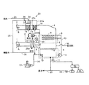
図1には、本発明の一実施例である湿式排煙脱硫装置(湿式石灰石−石膏法排煙脱硫装置)の系統を示す。なお、図1の湿式排煙脱硫装置において、図6の湿式排煙脱硫装置と同じ符号の部材の説明は一部省略している。 In FIG. 1, the system | strain of the wet flue gas desulfurization apparatus (wet limestone-gypsum method flue gas desulfurization apparatus) which is one Example of this invention is shown. In the wet flue gas desulfurization apparatus in FIG. 1, the description of members having the same reference numerals as those in the wet flue gas desulfurization apparatus in FIG. 6 is partially omitted.
火力発電所や工場等に設置されるボイラ等の燃焼装置から排出される硫黄酸化物を含む排ガスは矢印A方向から吸収塔4の入り口煙道1に設置されたガスガスヒータ(熱交換器)20を通り排ガスの熱が回収され、ガス温度は90〜110℃に低下する。ガス温度が一定値以下に低下した排ガスはガス入り口部3から湿式排煙脱硫装置の吸収塔4へと導入される。
An exhaust gas containing sulfur oxides discharged from a combustion apparatus such as a boiler installed in a thermal power plant or factory is a gas gas heater (heat exchanger) 20 installed in the
吸収塔4は液溜部5と吸収部(スプレ部)6から構成され、吸収部6では、排ガスの流れ方向に沿って上下に複数段の多数のスプレノズル9を備えたスプレヘッダ8が設置されており、スプレノズル9から微細な液滴として噴霧される石灰石または石灰を含むスラリなどの吸収剤の液滴と排ガスとを接触させることで、排ガス中のばいじんや塩化水素(HCl)、フッ化水素(HF)等の酸性ガスと共に、排ガス中の硫黄酸化物(SOx)はスプレノズル9の吸収液滴表面で化学的に吸収、除去される。
The absorption tower 4 is composed of a
液溜部5には、ボイラ等からの排ガスに含まれる硫黄酸化物の量に応じて、吸収剤スラリ(主に石灰石スラリ)供給ライン16から吸収剤が供給される。液溜部5にあるスラリ状の吸収液は、吸収液循環ポンプ10により昇圧され、吸収液循環配管13を経由して、吸収塔4内の上部の吸収部6のスプレヘッダ8に供給される。
The
また、排ガスの流れに同伴する微小な液滴(ミスト)は吸収塔4の上部のガス出口部18に設置されたミストエリミネータ7により除去される。ミストエリミネータ7を通過した排ガス温度は、通常、50℃程度の水分飽和ガスであるが、ミストエリミネータ7の排ガス流路下流に設置されるガスガスヒータ(熱交換器)20を通過することで再加熱される。すなわちミストエリミネータ7を通過した排ガスは、ガスガスヒータ20において回収された吸収塔4の入口ガスの熱によってガス温度が約90〜100℃程度まで再加熱され、出口煙道2から矢印B方向に流れ、最終的に煙突(図示せず)に導入された後、大気中に排出される。
Further, minute droplets (mist) accompanying the flow of the exhaust gas are removed by the mist eliminator 7 installed at the
吸収塔4の出口に設置されたミストエリミネータ7a,7bには、吸収塔4を循環する吸収液が飛散し、ミストエリミネータ7a,7bのエレメントに付着するため、水洗装置33を設けている。この水洗装置33については後に詳しく説明する。
The
ボイラ等から排出される排ガス中に含まれる二酸化硫黄(SO2)などの硫黄酸化物は、吸収液中に含まれるカルシウム化合物(石灰石(CaCO3)など)と反応し、中間生成物として亜硫酸カルシウム(重亜硫酸カルシウムを含む)になり、液溜部5に流下する。一方、液溜部5には、酸化用空気ブロワ17により酸化用空気供給ライン26から酸化用空気を強制的に供給し、該酸化用空気と亜硫酸カルシウムとの酸化反応により、反応生成物として石膏スラリ(CaSO4・2H2O)となる。
Sulfur oxides such as sulfur dioxide (SO 2 ) contained in exhaust gas discharged from boilers react with calcium compounds (limestone (CaCO 3 ), etc.) contained in the absorption liquid, and calcium sulfite as an intermediate product (Including calcium bisulfite) and flows down to the
なお、その際に液溜部5に供給する酸化用空気は、液溜部5内の吸収液を攪拌する酸化用攪拌機15により微細化されることにより、酸化用空気の利用率を高めている。液溜部5内の吸収液は概ね50℃程度であるが、酸化用空気ブロワ17出口の空気温度は、通常、120〜150℃であり、そのまま液溜部5に供給すると液溜部5の吸収液中に内挿した配管端部で乾湿の繰り返しが生じるため、酸化用空気ブロワ17出口の空気は、工業用水を直接噴霧することにより空気温度を水分飽和温度まで低下させ、液溜部5に供給される。
In this case, the oxidizing air supplied to the
液溜部5内の吸収液スラリは、吸収塔抜出しポンプ11により、生成石膏量に応じて液溜部5から石膏脱水設備12に抜き出されて脱水され、石膏14は回収される。一方、ろ液はろ液回収タンク21に貯留され、ろ液ポンプ22によって抜き出され、排水ライン23から湿式排煙脱硫装置の系外に排出される。
The absorbent slurry in the
また、湿式排煙脱硫装置の設備全体の水量バランスを維持するための補給水は、吸収塔4の液溜部供給ライン35とミストエリミネータ7の水洗水供給ライン37から供給される。
In addition, makeup water for maintaining the balance of the amount of water in the entire equipment of the wet flue gas desulfurization apparatus is supplied from a liquid
そして、本実施例によれば、ミストエリミネータ7a,7bを、少なくとも排ガス流路の上流側のミストエリミネータ7aと下流側のミストエリミネータ7b等の複数設置して、各ミストエリミネータ7a,7bに水洗水を供給する水洗水供給ライン37a,37bを設け、且つ下流側ミストエリミネータ7bの下流側水洗水供給ライン37bに海水供給ライン24を接続し、水洗水として海水と新水(工業用水)とを切り替えて供給できる構成の水洗装置33を設けたことを特徴としている。
According to this embodiment, a plurality of
海水と新水の切り替えは、海水供給ライン24と下流側ミストエリミネータ7bの下流側水洗水供給ライン37bとの接続部に設けた海水用切り替え弁(海水量調整手段)38と下流側水洗水供給ライン37bに設けた新水用切り替え弁(新水量調整手段)39の操作によって行い、また海水と新水の供給量を調整可能である。
Switching between seawater and fresh water is performed by changing the
上流側のミストエリミネータ7aには吸収塔4から多量の吸収液が飛散するため、ミストエリミネータへの付着物も多くなり、その水洗排水には多量の石膏等の固形物を含んでいる。したがって、上流側のミストエリミネータ7aの水洗排水は一旦吸収塔4に戻し、水洗排水は吸収塔4の補給水として再利用し、且つ固形物は吸収塔4の石膏抜き出しライン11から排出し、吸収液中の石膏14を回収する。
Since a large amount of absorbing liquid scatters from the absorption tower 4 to the
一方、上流側のミストエリミネータ7aの水洗水にも海水を使用した場合、海水中には塩素等の溶解塩が多量に含まれていることから、上流側のミストエリミネータ7aの水洗排水を吸収塔4に戻すと、吸収塔4内を循環する吸収液中の塩素濃度が高くなる。一般に、吸収液中の塩素濃度が高くなると吸収液のpHが低下し脱硫性能は低下する。また、水洗排水を湿式排煙脱硫装置の系外に排出する場合には、多量の固形物を含むため排水処理設備が必要となる。
On the other hand, when seawater is also used for the washing water of the
本実施例では、上流側のミストエリミネータ7aは上流側水洗水供給ライン37aより新水(工業用水)を用いて洗浄し、下流側のミストエリミネータ7bは海水供給ライン24より海水を用いて洗浄する。吸収塔4から飛散する固形物の多くは排ガス流路の上流側のミストエリミネータ7aにおいて捕集されており、下流側のミストエリミネータ7bへの固形物の付着量は少ない。したがって、下流側のミストエリミネータ7bの水洗排水(海水)は湿式排煙脱硫装置の系外にそのまま排出すれば良いため、排水処理設備を必要とせず、又は湿式排煙脱硫装置の設備の簡素化が可能となる。
In this embodiment, the
ミストエリミネータ7a,7bにおける合計水洗水量はボイラからの排ガス量、ミストエリミネータ7a,7bのエレメント構成にも依存するが、1000MW規模の火力発電設備の場合、概ね30〜40t/h程度である。
一方、本実施例によれば、下流側のミストエリミネータ7bの水洗水に海水を使用することにより、約10〜15t/hの水量を節減可能となる。
The total amount of water washed in the
On the other hand, according to the present embodiment, by using seawater as the washing water of the
このように、排ガス流路の下流側のミストエリミネータ7bは海水を用いて洗浄することで、吸収塔4へ供給する水量は低減し、ボイラ等の運転状態や運転負荷に関わらず、湿式排煙脱硫装置の設備全体の水量バランスを維持したままボイラ等の安定運用が可能となる。そして、湿式排煙脱硫装置の設備全体として必要となる補給水量も低減することが可能となる。
In this way, the
なお、本実施例では二つのミストエリミネータ7a,7bを設置した場合を示したが、ミストエリミネータを三つ以上設けても良い。三つの場合は、最も下流側のミストエリミネータか下流側の二つのミストエリミネータの水洗水に海水を使用すれば良い。
In the present embodiment, the case where two
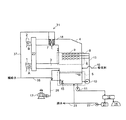
図2には、本発明の他の実施例である湿式排煙脱硫装置の系統を示す。
図2に示す湿式排煙脱硫装置は、図1の湿式排煙脱硫装置の吸収塔4の排ガス流路上流側にガス冷却器25を設け、更にガス冷却器25の冷却媒体量を調整するための制御装置40を設けた点で異なるが、それ以外は同様な構成である。
In FIG. 2, the system | strain of the wet flue gas desulfurization apparatus which is another Example of this invention is shown.
The wet flue gas desulfurization apparatus shown in FIG. 2 is provided with a
火力発電所や工場等に設置されるボイラ等の燃焼装置から排出される硫黄酸化物を含む排ガスは矢印A方向から吸収塔4の入り口煙道1に設置されたガスガスヒータ(熱交換器)20を通り排ガスの熱が回収され、ガス温度は90〜110℃に低下する。ガス温度が一定値以下に低下した排ガスは、吸収塔4の排ガス流路上流側に設けた多管式のガス冷却器25に導入される。
このガス冷却器25は、冷却媒体が通る管25aに海水供給ライン24を接続しており、ガス冷却器25の冷却媒体(内部媒体)として海水を供給できる設備構成にしている。したがって、ガス冷却器25の管内面を冷却媒体として海水供給ライン24から海水等の吸収塔の系外からの用水が流れ、管外面を排ガスが流れる。
An exhaust gas containing sulfur oxides discharged from a combustion apparatus such as a boiler installed in a thermal power plant or factory is a gas gas heater (heat exchanger) 20 installed in the
The
ガス冷却器25を通過して冷却された排ガスの温度は吸収塔入口ガス温度計30により測定される。吸収塔入口ガス温度計30により測定される温度を所定値60〜80℃程度に維持するように、海水供給ライン24からガス冷却器25に供給する海水量を制御装置40によって制御可能な構成である。海水供給ライン24から供給される海水量は、冷却媒体用の管25aの入り口に設けた海水量調整弁42などの供給量調整手段によって調整される。
The temperature of the exhaust gas cooled by passing through the
そして、吸収塔入口ガス温度計30により測定される温度が制御装置40に電気信号として入力され、この温度が所定値を維持するように、制御装置40からは海水量調整弁42に電気信号が出力されることでガス冷却器25の冷却媒体用の管25aに導入される海水量が決まる。
Then, the temperature measured by the absorption tower
このようにガス冷却器25に供給する海水量を制御装置40によって制御することで、ボイラ等の運転状態、運転負荷によらず、湿式排煙脱硫装置の設備全体の水量バランスを維持したままボイラ等の安定運用が可能となる。そして、湿式排煙脱硫装置の設備全体として必要となる補給水量も低減することが可能となる。また、ガス冷却器25内部の冷却媒体は、ガス冷却器25の通過前後で組成は変化しないため、使用した水の排水処理等が不要である。
By controlling the amount of seawater supplied to the
そして、ガス冷却器25を通過したボイラ等からの排ガスは、その後、吸収塔4に導入され、図1の湿式排煙脱硫装置と同様に吸収液との気液接触により、排ガス中に含まれる硫黄酸化物や塩化水素、フッ化水素等の酸性ガスを必要量除去した後、煙突から排出される。
And the exhaust gas from the boiler etc. which passed the
従来、火力発電所や工場等に設置されるボイラ等からの排ガスは、排ガス温度が比較的高温のまま吸収塔4内に導入されるため、吸収塔4内における蒸発水量が多くなるといった問題があった。吸収塔4内における蒸発水量は、吸収塔4の入口ガス温度と吸収塔4における処理ガス量、及び排ガス中の水分量等の排ガス組成に依存する。 Conventionally, exhaust gas from boilers and the like installed in thermal power plants and factories is introduced into the absorption tower 4 while the exhaust gas temperature is relatively high, so there is a problem that the amount of evaporated water in the absorption tower 4 increases. there were. The amount of evaporated water in the absorption tower 4 depends on the exhaust gas composition such as the inlet gas temperature of the absorption tower 4, the amount of treated gas in the absorption tower 4, and the amount of water in the exhaust gas.
一例として、1000MW規模の火力発電設備における、吸収塔4の入口ガス温度と吸収塔4内における蒸発水量の相関図を図5に示す。
図5からも明らかなように、従来は、吸収塔4の入口ガス温度が概ね90℃で運用していたものを10℃低下させることにより、約15t/h程度の蒸発水量が低減される。したがって、本実施例によれば、ガス冷却器25を吸収塔4の入口に設置し、且つガス冷却器25の冷却媒体として海水を供給することにより、湿式排煙脱硫装置全体の必要な補給水量を大幅に節減できる。
As an example, FIG. 5 shows a correlation diagram between the inlet gas temperature of the absorption tower 4 and the amount of evaporated water in the absorption tower 4 in a 1000 MW scale thermal power generation facility.
As apparent from FIG. 5, the amount of evaporated water of about 15 t / h is reduced by reducing the temperature of the absorption gas at the inlet 4 of the absorption tower 4 that is conventionally operated at about 90 ° C. by 10 ° C. Therefore, according to this embodiment, the
図3には、本発明の他の実施例である湿式排煙脱硫装置の系統を示す。
図3に示す湿式排煙脱硫装置は、図2の湿式排煙脱硫装置の吸収塔4の排ガス流路上流側にガスガスヒータ20を設けていない点で異なるが、それ以外は同様な構成であるので、説明は省略する。
In FIG. 3, the system | strain of the wet flue gas desulfurization apparatus which is another Example of this invention is shown.
The wet flue gas desulfurization apparatus shown in FIG. 3 is different in that the
火力発電所や工場等に設置されるボイラ等の燃焼装置から排出される硫黄酸化物を含む排ガスは矢印A方向から吸収塔4のガス入り口部3に設置された多管式のガス冷却器25に導入される。多管式のガス冷却器25では、吸収塔入口ガス温度計30により測定される温度を所定値60〜80℃程度に維持するように、制御装置40によって海水供給ライン24からガス冷却器25に供給する海水量が制御される。海水供給ライン24から供給される海水量は、冷却媒体用の管25aの入り口に設けた海水量調整弁42などの供給量調整手段によって調整される。
Exhaust gas containing sulfur oxides discharged from a combustion apparatus such as a boiler installed in a thermal power plant or factory is a multi-tube gas cooler 25 installed at the
基本的に、作用効果は実施例2(図2)と同様であるが、ガスガスヒータ20により事前にガス温度が低下しない分、ガス冷却器25の入り口ガス温度は高くなり、ガス冷却器25を設置していない場合は、より多くの補給水が必要となる。ガス冷却器25を設置することで、補給水の低減効果は高くなる。
本構成によれば、ガス冷却器25の容量(伝熱面積)は大きくなるが、ガスガスヒータ20を設けていないため、簡素な構成となる。
Basically, the operational effects are the same as those of the second embodiment (FIG. 2), but the gas temperature at the inlet of the
According to this structure, although the capacity | capacitance (heat-transfer area) of the
図4には、本発明の他の実施例である湿式排煙脱硫装置の系統を示す。
図4に示す湿式排煙脱硫装置は、図1の湿式排煙脱硫装置の吸収塔に供給する酸化用空気を冷却する空気冷却器27を設けた点で異なるが、それ以外は同様な構成である。
In FIG. 4, the system | strain of the wet flue gas desulfurization apparatus which is another Example of this invention is shown.
The wet flue gas desulfurization apparatus shown in FIG. 4 is different in that an
酸化用空気供給ライン26に空気冷却器27を設置し、空気冷却器27の冷却媒体が通る管27aに海水供給ライン24を接続することで、空気冷却器27の冷却媒体(内部媒体)として海水を供給できる設備構成にしている。
By installing an
通常、酸化用空気ブロワ17の出口空気温度は120〜150℃の高温空気であり、そのまま吸収塔4の液溜部5に供給すると、液溜部5の吸収液中に内挿した配管端部で乾湿の繰り返しが生じるため、酸化用空気ブロワ17出口の空気は、工業用水の直接噴霧により空気温度を水分飽和温度まで低下させて液溜部5に供給される。この時に噴霧する水量は除去する硫黄酸化物量に応じて決定される酸化用空気量に依存するが、1000MW規模の火力発電設備の場合、概ね1〜2t/h程度である。
Normally, the outlet air temperature of the oxidizing
しかし、本実施例によれば、酸化用空気供給ライン26に酸化用空気を冷却する空気冷却器27を設置し、且つ空気冷却器27の冷却媒体として海水を使用することにより、吸収塔4の酸化用空気増湿水量の低減が図れ、概ね1〜2t/h(工業用水量、すなわち海水量)の水量が節減できる。空気冷却器27の冷却媒体に使用する海水量は冷却媒体用の管27aの入り口に設けた海水量調整弁42によって調整できる。
However, according to the present embodiment, an
更に、酸化用空気ブロワ17出口に酸化用空気温度を測定する温度計(図示せず)を設け、この温度計の測定値によって水分飽和温度になるように、海水供給ライン24から空気冷却器27に供給する海水量を制御装置40(図2等)によって制御可能な構成としても良い。
また、図2や図3の湿式排煙脱硫装置に酸化用空気を冷却する空気冷却器27を設けても良い。空気冷却器27を設置した方が、より補給水の低減を図ることができる。
Further, a thermometer (not shown) for measuring the temperature of the oxidizing air is provided at the outlet of the oxidizing
Moreover, you may provide the
そして、これらの実施例1〜4に示す通り、本発明によれば、吸収塔4のミストエリミネータ7a,7bの水洗水量の低減、吸収塔4内における蒸発水量の低減、及び吸収塔4の酸化用空気増湿水量の低減が可能となり、湿式排煙脱硫装置において必要となる用水量の低減効果が見込め、用水量の確保が困難な地域に対しても有用である。
And as shown in these Examples 1-4, according to this invention, the reduction of the amount of washing water of the
また、上述の実施例等は、排ガスが水平方向に流れる水平流型吸収塔とした場合や二室型の吸収塔とした場合にも適用できる。 Moreover, the above-mentioned Example etc. are applicable also when it is set as the horizontal flow type absorption tower which waste gas flows into a horizontal direction, or when it is set as a two-chamber type absorption tower.
湿式排煙脱硫装置などにおいて、補給水量を低減可能な技術として利用可能性がある。 In wet flue gas desulfurization equipment and the like, it may be used as a technology that can reduce the amount of makeup water.
1 入り口煙道 2 出口煙道
3 吸収塔ガス入口部 4 吸収塔
5 吸収塔液溜部 6 吸収塔吸収部(スプレ部)
7 ミストエリミネータ 7a 上流側のミストエリミネータ
7b 下流側のミストエリミネータ
8 スプレヘッダ
9 スプレノズル 10 吸収液循環ポンプ
11 吸収液抜出しポンプ 12 石膏脱水設備
13 吸収液循環配管 14 石膏
15 酸化用攪拌機 16 吸収剤スラリ供給ライン
17 酸化用空気ブロワ 18 吸収塔ガス出口部
20 ガスガスヒータ(熱交換器)
21 ろ液回収タンク 22 ろ液ポンプ
23 排水ライン 24 海水供給ライン
25 ガス冷却器 25a 冷却媒体用の管
26 酸化用空気供給ライン
27 酸化用空気冷却器 27a 冷却媒体用の管
30 吸収塔入口ガス温度計 31,33 水洗装置
35 液溜部供給ライン 37 水洗水供給ライン
37a 上流側水洗水供給ライン
37b 下流側水洗水供給ライン
38 海水用切り替え弁 39 新水用切り替え弁
40 制御装置 42 海水量調整弁
DESCRIPTION OF
7
21
Claims (6)
前記ミストエリミネータを排ガス流路の上流側と下流側に複数設け、前記ミストエリミネータ水洗装置に前記各ミストエリミネータに水洗用の水を供給する水洗水供給部を設け、前記下流側のミストエリミネータの水洗水供給部に海水を供給する海水供給部を設けたことを特徴とする排煙脱硫装置。 An absorption tower for absorbing and removing sulfur oxides contained in the exhaust gas by introducing exhaust gas discharged from a combustion apparatus including a boiler, spraying an absorption liquid on the exhaust gas, and bringing it into gas-liquid contact, and the absorption In the flue gas desulfurization apparatus provided with the mist eliminator that is provided at the outlet of the exhaust gas flow path of the tower and collects the mist discharged from the absorption tower, and the mist eliminator water washing device that rinses the mist eliminator,
A plurality of the mist eliminators are provided on the upstream side and the downstream side of the exhaust gas flow path, and the mist eliminator flushing device is provided with a flush water supply unit for supplying flush water to each mist eliminator, and the downstream mist eliminator is flushed. A flue gas desulfurization apparatus comprising a seawater supply section for supplying seawater to a water supply section.
前記冷却媒体用の管に海水を供給する海水供給部を設けたことを特徴とする請求項1記載の排煙脱硫装置。 An exhaust gas cooler having a cooling medium pipe inside is provided at the inlet of the exhaust gas flow path of the absorption tower,
The flue gas desulfurization apparatus according to claim 1, further comprising a seawater supply unit configured to supply seawater to the cooling medium pipe.
該酸化用空気供給部に、内部に冷却媒体用の管を有する酸化用空気冷却器を設け、
前記冷却媒体用の管に海水を供給する海水供給部を設けたことを特徴とする請求項1記載の排煙脱硫装置。 An oxidizing air supply unit for supplying oxidizing air to the absorption tower is provided,
The oxidation air supply unit is provided with an oxidation air cooler having a cooling medium pipe inside,
The flue gas desulfurization apparatus according to claim 1, further comprising a seawater supply unit configured to supply seawater to the cooling medium pipe.
前記下流側のミストエリミネータの水洗水に海水を使用することを特徴とする排煙脱硫方法。 The exhaust gas discharged from the combustion apparatus including the boiler is introduced into the absorption tower, sprayed with the absorbing liquid, and brought into gas-liquid contact with the exhaust gas, thereby absorbing and removing sulfur oxides contained in the exhaust gas, and then absorbing the absorption This is a flue gas desulfurization method in which mist discharged from the tower is collected by a plurality of mist eliminators provided upstream and downstream of the outlet of the exhaust gas passage of the absorption tower, and the mist eliminator collecting the mist is washed with water. And
A flue gas desulfurization method using seawater for washing water of the downstream mist eliminator.
Priority Applications (1)
| Application Number | Priority Date | Filing Date | Title |
|---|---|---|---|
| JP2011061259A JP2012196611A (en) | 2011-03-18 | 2011-03-18 | Flue gas desulfurization apparatus and flue gas desulfurization method |
Applications Claiming Priority (1)
| Application Number | Priority Date | Filing Date | Title |
|---|---|---|---|
| JP2011061259A JP2012196611A (en) | 2011-03-18 | 2011-03-18 | Flue gas desulfurization apparatus and flue gas desulfurization method |
Publications (1)
| Publication Number | Publication Date |
|---|---|
| JP2012196611A true JP2012196611A (en) | 2012-10-18 |
Family
ID=47179379
Family Applications (1)
| Application Number | Title | Priority Date | Filing Date |
|---|---|---|---|
| JP2011061259A Pending JP2012196611A (en) | 2011-03-18 | 2011-03-18 | Flue gas desulfurization apparatus and flue gas desulfurization method |
Country Status (1)
| Country | Link |
|---|---|
| JP (1) | JP2012196611A (en) |
Cited By (6)
| Publication number | Priority date | Publication date | Assignee | Title |
|---|---|---|---|---|
| CN103007694A (en) * | 2012-12-27 | 2013-04-03 | 上海海事大学 | Seawater desulfurization device for tail gas of marine diesel engine |
| CN104474861A (en) * | 2014-11-13 | 2015-04-01 | 中国石油化工股份有限公司 | Skid-mounted liquid sulfur tank tail gas purifying oxidation absorbing apparatus |
| CN104607013A (en) * | 2013-11-05 | 2015-05-13 | 中国石油化工股份有限公司 | H-shaped flue gas dust removal desulfurization tower and flue gas desulfurization process |
| CN109999627A (en) * | 2018-01-05 | 2019-07-12 | 北京万信同和能源科技有限公司 | Wet plume abatement equipment and method for catalytic cracking wet desulphurization device |
| WO2022113924A1 (en) * | 2020-11-24 | 2022-06-02 | 三菱重工業株式会社 | Desulfurizing device |
| CN116371165A (en) * | 2023-04-07 | 2023-07-04 | 北京翰海青天环保科技有限公司 | An environment-friendly dust removal and desulfurization integrated equipment |
Citations (7)
| Publication number | Priority date | Publication date | Assignee | Title |
|---|---|---|---|---|
| JPS49119868A (en) * | 1973-03-20 | 1974-11-15 | ||
| JPH06126127A (en) * | 1992-10-15 | 1994-05-10 | Babcock Hitachi Kk | Method and apparatus for simultaneous treatment of dust collection and desulfurization |
| JPH06134251A (en) * | 1992-10-22 | 1994-05-17 | Chiyoda Corp | Method of reducing make-up water to wet desulfurization equipment |
| JPH06285326A (en) * | 1993-04-05 | 1994-10-11 | Chiyoda Corp | Method and device for flue gas desulfurization |
| JPH07155538A (en) * | 1993-12-06 | 1995-06-20 | Chiyoda Corp | Exhaust gas desulfurization method |
| JPH08229341A (en) * | 1995-02-23 | 1996-09-10 | Mitsui Mining Co Ltd | Gas-liquid contacting method and device thereof |
| JPH09173764A (en) * | 1995-12-22 | 1997-07-08 | Babcock Hitachi Kk | Wet flue gas desulfurizer and method thereof |
-
2011
- 2011-03-18 JP JP2011061259A patent/JP2012196611A/en active Pending
Patent Citations (7)
| Publication number | Priority date | Publication date | Assignee | Title |
|---|---|---|---|---|
| JPS49119868A (en) * | 1973-03-20 | 1974-11-15 | ||
| JPH06126127A (en) * | 1992-10-15 | 1994-05-10 | Babcock Hitachi Kk | Method and apparatus for simultaneous treatment of dust collection and desulfurization |
| JPH06134251A (en) * | 1992-10-22 | 1994-05-17 | Chiyoda Corp | Method of reducing make-up water to wet desulfurization equipment |
| JPH06285326A (en) * | 1993-04-05 | 1994-10-11 | Chiyoda Corp | Method and device for flue gas desulfurization |
| JPH07155538A (en) * | 1993-12-06 | 1995-06-20 | Chiyoda Corp | Exhaust gas desulfurization method |
| JPH08229341A (en) * | 1995-02-23 | 1996-09-10 | Mitsui Mining Co Ltd | Gas-liquid contacting method and device thereof |
| JPH09173764A (en) * | 1995-12-22 | 1997-07-08 | Babcock Hitachi Kk | Wet flue gas desulfurizer and method thereof |
Cited By (9)
| Publication number | Priority date | Publication date | Assignee | Title |
|---|---|---|---|---|
| CN103007694A (en) * | 2012-12-27 | 2013-04-03 | 上海海事大学 | Seawater desulfurization device for tail gas of marine diesel engine |
| CN103007694B (en) * | 2012-12-27 | 2014-09-24 | 上海海事大学 | Marine diesel engine exhaust seawater desulfurization device |
| CN104607013A (en) * | 2013-11-05 | 2015-05-13 | 中国石油化工股份有限公司 | H-shaped flue gas dust removal desulfurization tower and flue gas desulfurization process |
| CN104607013B (en) * | 2013-11-05 | 2017-02-08 | 中国石油化工股份有限公司 | H-shaped flue gas dust removal desulfurization tower and flue gas desulfurization process |
| CN104474861A (en) * | 2014-11-13 | 2015-04-01 | 中国石油化工股份有限公司 | Skid-mounted liquid sulfur tank tail gas purifying oxidation absorbing apparatus |
| CN109999627A (en) * | 2018-01-05 | 2019-07-12 | 北京万信同和能源科技有限公司 | Wet plume abatement equipment and method for catalytic cracking wet desulphurization device |
| WO2022113924A1 (en) * | 2020-11-24 | 2022-06-02 | 三菱重工業株式会社 | Desulfurizing device |
| JP7604187B2 (en) | 2020-11-24 | 2024-12-23 | 三菱重工業株式会社 | Desulfurization Equipment |
| CN116371165A (en) * | 2023-04-07 | 2023-07-04 | 北京翰海青天环保科技有限公司 | An environment-friendly dust removal and desulfurization integrated equipment |
Similar Documents
| Publication | Publication Date | Title |
|---|---|---|
| KR101732298B1 (en) | Cleaning system and method for reduction of sox in exhaust gases | |
| JP6223654B2 (en) | Flue gas desulfurization equipment | |
| JP5773687B2 (en) | Seawater flue gas desulfurization system and power generation system | |
| CN103894051B (en) | A kind of smoke-gas wet desulfurization denitrification integral system and method | |
| JP2012239958A (en) | Wet type flue gas desulfurizing apparatus and method | |
| JP2013086054A (en) | Wet type limestone-gypsum method desulfurization apparatus using seawater | |
| WO2011132660A1 (en) | Exhaust gas treatment system having carbon dioxide removal device | |
| JP2012179521A5 (en) | ||
| KR20140031144A (en) | Desulphurization and cooling of process gas | |
| JP2012196611A (en) | Flue gas desulfurization apparatus and flue gas desulfurization method | |
| JP2013039511A (en) | Wet type flue-gas desulfurization apparatus and thermal power plant having the same | |
| JP2015073955A (en) | Exhaust gas treatment method, and exhaust gas treatment device | |
| JP4587197B2 (en) | Wet flue gas desulfurization method and apparatus | |
| WO2013115108A1 (en) | Oxidation tank, seawater flue-gas desulfurization system and power generation system | |
| JP2015116520A (en) | Wet type flue-gas desulfurization apparatus and application method of the wet type flue-gas desulfurization apparatus | |
| EP2644254B1 (en) | Scrubber for cleaning a process gas and recovering heat | |
| JP3572188B2 (en) | Exhaust gas treatment method | |
| JP2014200768A (en) | Seawater type exhaust gas desulfurizer | |
| CN209917622U (en) | Haze integrated device and clean system are controlled to efficiency | |
| JP5019361B2 (en) | How to cope with increase of absorbent slurry concentration in flue gas desulfurization equipment | |
| CN210145833U (en) | White smoke plume remove device with thick liquid cooling tray | |
| CN114797434A (en) | Device and method for deep emission reduction and waste heat utilization of secondary spraying in desulfurizing tower and water collection of flue gas | |
| WO2000048711A1 (en) | Gas cooling device, gas treatment device, and boiler equipment | |
| JPH0663353A (en) | Wet flue gas desulfurizer and its method | |
| CN205235747U (en) | A technological device for highly efficient removal of SO3 by washing with alkaline solution in a spray desulfurization tower |
Legal Events
| Date | Code | Title | Description |
|---|---|---|---|
| A621 | Written request for application examination |
Free format text: JAPANESE INTERMEDIATE CODE: A621 Effective date: 20131016 |
|
| A977 | Report on retrieval |
Free format text: JAPANESE INTERMEDIATE CODE: A971007 Effective date: 20140523 |
|
| A131 | Notification of reasons for refusal |
Free format text: JAPANESE INTERMEDIATE CODE: A131 Effective date: 20140603 |
|
| A02 | Decision of refusal |
Free format text: JAPANESE INTERMEDIATE CODE: A02 Effective date: 20141014 |