JP2012196639A - Apparatus for crushing and mixing earth and sand, and method using the same - Google Patents
Apparatus for crushing and mixing earth and sand, and method using the same Download PDFInfo
- Publication number
- JP2012196639A JP2012196639A JP2011063370A JP2011063370A JP2012196639A JP 2012196639 A JP2012196639 A JP 2012196639A JP 2011063370 A JP2011063370 A JP 2011063370A JP 2011063370 A JP2011063370 A JP 2011063370A JP 2012196639 A JP2012196639 A JP 2012196639A
- Authority
- JP
- Japan
- Prior art keywords
- earth
- sand
- crushing
- processing container
- air
- Prior art date
- Legal status (The legal status is an assumption and is not a legal conclusion. Google has not performed a legal analysis and makes no representation as to the accuracy of the status listed.)
- Granted
Links
Images


Landscapes
- Crushing And Pulverization Processes (AREA)
- Disintegrating Or Milling (AREA)
- Mixers With Rotating Receptacles And Mixers With Vibration Mechanisms (AREA)
- Mixers Of The Rotary Stirring Type (AREA)
Abstract
【課題】衝撃付与を利用した破砕処理、混合処理あるいは破砕混合同時処理を行う際、破砕効率や混合効率を向上させる。
【解決手段】本発明に係るに係る土砂の改質装置1は、処理容器2の内部空間に衝撃付与機構3を配置するとともに、該処理容器を構成する最下段の角筒体2aの側板のうち、土砂排出口12が形成された側板と直交する側板には空気流入口21を、最上段の角筒体2cの側板のうち、土砂投入口10が形成された側板と直交する側板には排気口24をそれぞれ形成し、空気流入口21を介した送気及び排気口24を介した排気によって、処理容器2内に上方への空気流を形成するようになっており、かかる空気流は、投入土砂の落下速度を低下させて衝撃付与機構3の土砂破砕作用を高める。
【選択図】 図1
[PROBLEMS] To improve crushing efficiency and mixing efficiency when performing crushing processing, mixing processing or crushing and mixing simultaneous processing using impact application.
An earth and sand reforming apparatus according to the present invention has an impact applying mechanism arranged in an internal space of a processing container, and a side plate of a lowermost rectangular tube body that constitutes the processing container. Among them, the air inlet 21 is provided on the side plate orthogonal to the side plate on which the earth and sand discharge port 12 is formed, and the side plate orthogonal to the side plate on which the earth and sand inlet 10 is formed among the side plates of the uppermost rectangular tube 2c. An exhaust port 24 is formed, and an upward air flow is formed in the processing container 2 by air supply through the air inflow port 21 and exhaust through the exhaust port 24. Then, the falling speed of the introduced earth and sand is reduced to increase the earth and sand crushing action of the impact applying mechanism 3.
[Selection] Figure 1
Description
本発明は、土木建築工事で用いる土に対し、破砕処理、混合処理又は破砕混合同時処理を行う場合に適用される土砂の破砕混合装置及びそれを用いた方法に関する。 The present invention relates to an earth and sand crushing and mixing apparatus applied when performing crushing, mixing, or simultaneous crushing and mixing for soil used in civil engineering construction, and a method using the same.
土木建築工事で用いる土は、粒度調整などを目的として破砕処理を行なう場合があり、その方法として、チェーン状部材を旋回させながら、その旋回範囲に土砂を自然落下させることにより、土砂に衝撃力を与えて破砕する方法が知られている。 The soil used in civil engineering construction work may be crushed for the purpose of particle size adjustment, etc. As a method, impact force is applied to the earth and sand by allowing the earth and sand to fall naturally in the swiveling range while turning the chain member. A method of crushing by giving is known.
かかる方法においては、破砕が主体となる場合のほか、破砕時に飛散作用も発揮されることから、異なる種類の土同士や、固化材や添加剤あるいは活性炭が添加された土に対し、破砕処理と混合処理を同時に行うこともできる。 In such a method, in addition to the case where crushing is mainly performed, the scattering action is also exhibited at the time of crushing, so crushing treatment can be performed on different types of soils or soils to which solidifying material, additive, or activated carbon is added. The mixing process can be performed simultaneously.
一方、破砕が十分に進行している土であって、上述したような固化材や添加剤あるいは活性炭が添加されている場合においては、衝撃力が付与されたときの飛散作用による混合処理が可能である。 On the other hand, when the soil is sufficiently crushed and has added a solidifying material, additive, or activated carbon as described above, it is possible to perform a mixing process by scattering when an impact force is applied. It is.
このような衝撃付与を利用した破砕処理、混合処理あるいは破砕混合同時処理は、土砂を連続投入しながら処理を進めることができるため、パドルミキサー等のバッチ式処理装置に比べ、処理効率がはるかに高い。そのため、大規模現場では、その活用が大いに期待されている。 The crushing process, mixing process or simultaneous crushing / mixing process using the application of impact can proceed with the continuous addition of earth and sand, so the processing efficiency is much higher than that of batch type processing equipment such as paddle mixers. high. Therefore, its use is greatly expected in large-scale sites.
しかしながら、チェーン状部材の旋回による破砕作用あるいは飛散作用は、土砂の自然落下中に限られるため、土砂の破砕や飛散が十分ではなく、結果として所望の粒度が得られなかったり、十分な混合が行われなかったりするおそれがあり、これらを回避しようとすれば、旋回による破砕や飛散を繰り返し行う必要が生じ、破砕効率や混合効率の低下につながるという問題を生じていた。 However, since the crushing action or scattering action by the turning of the chain member is limited to the natural fall of the earth and sand, the earth and sand are not sufficiently crushed and scattered, and as a result, the desired particle size cannot be obtained or sufficient mixing is performed. There is a possibility that it may not be performed, and if it is attempted to avoid these, it has become necessary to repeatedly perform crushing and scattering by swirling, resulting in a problem of reduced crushing efficiency and mixing efficiency.
本発明は、上述した事情を考慮してなされたもので、衝撃付与を利用した破砕処理、混合処理あるいは破砕混合同時処理を行う際、破砕効率や混合効率を向上させることが可能な土砂の破砕混合装置及びそれを用いた方法を提供することを目的とする。 The present invention has been made in consideration of the above-described circumstances, and crushing of earth and sand capable of improving crushing efficiency and mixing efficiency when performing crushing processing, mixing processing, or crushing mixing simultaneous processing using impact application. It is an object to provide a mixing apparatus and a method using the mixing apparatus.
上記目的を達成するため、本発明に係る土砂の破砕混合装置は請求項1に記載したように、上方に土砂投入口が設けられ下方に土砂排出口が設けられた処理容器と、材軸がほぼ鉛直になるようにかつ該材軸廻りに回転自在となるように前記処理容器に保持されたシャフト及び該シャフトの周面に基端側が取り付けられた衝撃付与部材とからなり前記土砂投入口から投入された土砂が前記シャフトの回転に伴う前記衝撃付与部材の旋回範囲に自然落下するように構成された衝撃付与機構と、前記衝撃付与部材の下方位置に拡がる前記処理容器の内部空間に連通するように該処理容器に形成された空気流入口から流入した空気を前記衝撃付与部材の上方位置に拡がる前記処理容器の内部空間に連通するように該処理容器に形成された排気口を介して前記処理容器から排出する排気手段とを備えるとともに、前記排気手段を前記衝撃付与機構とともに同時作動させるように構成したものである。
In order to achieve the above object, the earth and sand crushing and mixing apparatus according to the present invention comprises a processing container having an earth and sand inlet in the upper part and a earth and sand outlet in the lower part and a material shaft, as described in
また、本発明に係る土砂の破砕混合装置は、前記処理容器の内部空間に空気を供給する送気手段を前記空気流入口に接続したものである。 In the earth and sand crushing and mixing apparatus according to the present invention, an air supply means for supplying air to the internal space of the processing container is connected to the air inlet.
また、本発明に係る土砂の破砕混合装置は、前記排気手段及び前記送気手段を、排気流量が送気流量よりも大きくなるように構成したものである。 In the earth and sand crushing and mixing apparatus according to the present invention, the exhaust means and the air supply means are configured such that the exhaust flow rate is larger than the air supply flow rate.
また、本発明に係る土砂の破砕混合装置は、前記排気口を、前記衝撃付与部材の上方位置で互いに対向するようにかつ前記土砂投入口に対して直角方向の角度位置となるように前記処理容器に形成された一対の排気口で構成するとともに、該一対の排気口に前記排気手段を構成する吸気ブロワをそれぞれ連通接続したものである。 Further, in the earth and sand crushing and mixing apparatus according to the present invention, the processing is performed so that the exhaust ports are opposed to each other at an upper position of the impact applying member and at an angular position in a direction perpendicular to the earth and sand inlet. In addition to a pair of exhaust ports formed in the container, an intake blower that constitutes the exhaust means is connected to the pair of exhaust ports.
また、本発明に係る土砂の破砕混合装置は、一対の仕切板を、それぞれが前記一対の排気口に対向するようにかつ互いに前記シャフトの反対側に位置するように前記衝撃付与部材の上方に配置したものである。 Further, the earth and sand crushing and mixing apparatus according to the present invention includes a pair of partition plates disposed above the impact applying member so that each of the partition plates faces the pair of exhaust ports and is opposite to the shaft. It is arranged.
また、本発明に係る土砂の破砕混合装置は、前記衝撃付与部材の配置空間を通過した空気の流れが2方向に分岐しそれぞれが前記一対の排気口に向けて案内されるように前記衝撃付与部材の上方にガイド部材を配置したものである。 In the earth and sand crushing and mixing apparatus according to the present invention, the impact application is performed so that the flow of air that has passed through the placement space of the impact application member branches in two directions and is guided toward the pair of exhaust ports. A guide member is arranged above the member.
また、本発明に係る土砂の破砕混合方法は請求項7に記載したように、処理容器の上方に形成された土砂投入口から土砂を投入するとともに、前記処理容器内に配置された衝撃付与機構を作動させてそれを構成するシャフトをほぼ鉛直となる軸線廻りに回転させることにより、該シャフトの周面に基端側が取り付けられた衝撃付与部材を水平面内で旋回させ、前記土砂投入口を介して投入された土砂を前記衝撃付与部材の旋回範囲に自然落下させることにより、該土砂を破砕して前記処理容器の下方に形成された土砂排出口を介して搬出する土砂の破砕混合方法であって、
前記衝撃付与部材を旋回させながら、前記衝撃付与部材の上方位置に拡がる前記処理容器の内部空間からの空気排出を行うものである。
Further, according to the method for crushing and mixing earth and sand according to the present invention, as described in
While rotating the impact applying member, air is discharged from the internal space of the processing container which extends to a position above the impact applying member.
また、本発明に係る土砂の破砕混合方法は、前記衝撃付与部材の下方位置に拡がる前記処理容器の内部空間への空気供給を同時に行うものである。 The earth and sand crushing and mixing method according to the present invention simultaneously supplies air to the internal space of the processing container that extends to a position below the impact imparting member.
また、本発明に係る土砂の破砕混合方法は、排気流量を送気流量よりも大きくするものである。 The earth and sand crushing and mixing method according to the present invention makes the exhaust flow rate larger than the air supply flow rate.
本発明に係る土砂の破砕混合装置を用いて土砂の破砕処理、混合処理又は破砕混合同時処理を行うには、シャフトを回転させることによって該シャフトの材軸廻りに衝撃付与部材を旋回させるとともに、土砂投入口を介して対象土砂を処理容器内に投入する一方、排気手段を作動させる。 In order to perform soil crushing processing, mixing processing or crushing and mixing simultaneous processing using the earth and sand crushing and mixing apparatus according to the present invention, by rotating the shaft, the impact applying member is turned around the shaft of the shaft, The target sediment is introduced into the processing container through the sediment introduction port, and the exhaust means is operated.
このようにすると、土砂投入口から投入された土砂は、衝撃付与部材の旋回範囲に自然落下して該衝撃付与部材と接触し、そのときの衝撃による破砕作用や飛散作用で土砂の破砕や混合が行われ、あるいは破砕処理と混合処理が同時に行われるが、本発明においては、衝撃付与部材の下方位置に拡がる処理容器の内部空間に連通するように該処理容器に形成された空気流入口から流入した空気が、衝撃付与部材の上方位置に拡がる処理容器の内部空間に連通するように該処理容器に形成された排気口を介して処理容器から排出されるので、処理容器の内部空間においては、下方から上方へと向かう空気の流れが形成され、かかる空気の流れは、土砂や土塊が落下する際の抵抗となって、それらの落下速度を低下させる。 In this way, the earth and sand thrown in from the earth and sand introduction port naturally falls into the swiveling range of the impact imparting member and comes into contact with the impact imparting member. In the present invention, from the air inlet formed in the processing container so as to communicate with the internal space of the processing container extending to the lower position of the impact applying member. Since the inflowing air is exhausted from the processing container through the exhaust port formed in the processing container so as to communicate with the internal space of the processing container spreading to the upper position of the impact applying member, in the internal space of the processing container, Then, an air flow from the lower side to the upper side is formed, and the air flow becomes a resistance when the earth and sand or the lump falls, and reduces the falling speed thereof.
そのため、衝撃付与部材が土砂や土塊に衝突する回数が増加し、かくして、より均一で細かい破砕処理が可能になるとともに、均質性が向上した混合処理が可能になる。 Therefore, the number of times that the impact applying member collides with the earth and sand or the lump is increased, and thus a more uniform and fine crushing process is possible, and a mixing process with improved homogeneity is possible.
本発明における破砕混合とは、典型的には、衝撃力で破砕されつつ破砕時の飛散作用が発揮されて混合が行われる破砕混合同時処理を意味するが、十分に破砕された土砂が処理対象である場合には、衝撃力が付与されたときの飛散作用による混合処理が主体となり、均質な土砂が処理対象である場合には、衝撃力による破砕処理が主体となる。そのため、本発明で破砕混合というときは、破砕混合同時処理のほか、破砕処理のみの場合と混合処理のみの場合を含むものとする。 The crushing and mixing in the present invention typically means a crushing and mixing simultaneous process in which mixing is performed by exerting the scattering action at the time of crushing while crushing with impact force, but sufficiently crushed earth and sand are to be treated. When the impact force is applied, the mixing process is mainly performed by the scattering action. When the homogeneous earth and sand is a processing target, the crushing process by the impact force is mainly performed. For this reason, the crushing and mixing in the present invention includes not only simultaneous crushing and mixing processing but also crushing only and mixing only.
また、本発明における土砂の混合とは、土砂同士の混合のみならず、固化材、添加剤、活性炭その他の土砂に添加される物質と土砂との混合も包摂される。 In addition, mixing of earth and sand in the present invention includes not only mixing of earth and sand but also mixing of a material added to a solidifying material, an additive, activated carbon and other earth and sand with earth and sand.
衝撃付与部材は、その基端側が取り付けられたシャフトを回転させることによって、該シャフトの回転軸線廻りに旋回し、該旋回動作によって処理容器内に投入された土砂に衝撃を付与し得るものであれば、その構造や形状は任意であって、例えば、全体を剛体又は可撓性材料で形成する構成や、複数の鋼製ピースを長さ方向に次々に連結することにより、全体としては可撓性材料として挙動するが、個々のピースについては剛体として挙動する構成が可能である。 The impact imparting member is capable of revolving around the rotation axis of the shaft by rotating the shaft to which the base end side is attached, and imparting impact to the earth and sand introduced into the processing container by the revolving operation. For example, the structure and shape are arbitrary. For example, the entire structure is formed of a rigid body or a flexible material, or a plurality of pieces of steel are connected one after another in the length direction, thereby being flexible as a whole. It can be configured to behave as a rigid body although it behaves as a material.
さらに具体的に説明すると、全体を剛体で構成する例としては、衝撃付与部材を鋼製のロッド材とし、複数の鋼製ピースを鎖状に次々に連結する例としては、衝撃付与部材を鋼製のチェーンとする構成を挙げることが可能である。 More specifically, as an example in which the whole is constituted by a rigid body, the impact applying member is a steel rod material, and as an example of connecting a plurality of steel pieces one after another in a chain, the impact applying member is a steel rod. It is possible to mention the configuration as a chain made of metal.
ちなみに、全体を可撓性材料で構成する場合や、複数の鋼製ピースを長さ方向に次々に連結する場合、衝撃付与部材は、シャフト静止時には該シャフトから垂れ下がった状態であるが、シャフト回転時には該シャフトの材軸廻りに旋回し、その旋回力によって、土砂を破砕する。 By the way, when the whole is made of a flexible material, or when connecting a plurality of steel pieces one after another in the length direction, the impact applying member is in a state where it hangs down from the shaft when the shaft is stationary. Sometimes it turns around the shaft of the shaft, and the earth and sand are crushed by the turning force.
衝撃付与部材は、旋回の際、所定角度ごとに放射方向に延びるよう、複数設置することができるとともに、自然落下する土砂が次々に衝撃力を受けることができるよう、鉛直方向に沿って複数段に配置することが可能である。 When turning, a plurality of impact imparting members can be installed so as to extend in a radial direction at predetermined angles, and a plurality of steps along the vertical direction are provided so that the naturally falling earth and sand can receive impact forces one after another. It is possible to arrange in
排気手段は、排気口を介して処理容器から空気を引き抜くことで、下方から上方へと向かう空気の流れを処理容器内に形成することができる限り、どのような構成とするかは任意であり、例えばブロワと該ブロワに一端が接続され他端が処理容器の排気口に接続されたダクトとで構成することが可能である。なお、処理容器内において下方から上方へと向かう空気の流れは、例えば1分間に数百回転する衝撃付与部材によって遮断されることがないよう、十分な流量を確保する。 As long as the exhaust means can draw air from the processing container through the exhaust port to form a flow of air from the bottom to the top in the processing container, the configuration of the exhaust means is arbitrary. For example, a blower and a duct having one end connected to the blower and the other end connected to the exhaust port of the processing container can be used. It should be noted that a sufficient flow rate is ensured so that the air flow from the lower side to the upper side in the processing container is not blocked by, for example, an impact applying member that rotates several hundreds per minute.
ここで、排気手段によって処理容器内から空気を引き抜く際、空気流入口を介して処理容器内に空気が自然導入されるようにしてもかまわないが、処理容器内に空気を供給する送気手段を空気流入口に接続したならば、衝撃付与部材の下方位置に拡がる処理容器の内部空間に空気を強制的に送り込むことができるため、上述した空気流量を確保しやすくなり、空気流を確実に形成することが可能となる。 Here, when the air is drawn out from the processing container by the exhaust means, the air may be naturally introduced into the processing container through the air inlet, but the air supply means for supplying the air into the processing container. Since the air can be forcibly fed into the internal space of the processing container that extends to the lower position of the impact applying member, the above-described air flow rate can be easily ensured, and the air flow can be ensured. It becomes possible to form.
送気手段は排気手段と同様、例えばブロワと該ブロワに一端が接続され他端が処理容器の空気流入口に接続されたダクトとで構成することが可能である。 Like the exhaust means, the air supply means can be constituted by, for example, a blower and a duct having one end connected to the blower and the other end connected to the air inlet of the processing vessel.
なお、処理容器の内部空間において、下方から上方へと向かう空気の流れをさらに確実に形成するためには、排気手段及び送気手段を、排気流量が送気流量よりも大きくなるように構成するのが望ましい。 In order to more reliably form an air flow from the lower side to the upper side in the internal space of the processing container, the exhaust means and the air supply means are configured so that the exhaust flow rate is larger than the air supply flow rate. Is desirable.
排気口は、衝撃付与部材の上方に設ける必要があるため、土砂投入口と同程度の高さにならざるを得ないが、土砂投入口から投入された土砂が自然落下せずに排気口に直接吸引されると、対象となる土砂に対して破砕混合が行われないばかりか、土塊が排気口廻りに付着し、空気の流れを阻害する事態となることが懸念される。 Since the exhaust port must be provided above the impact imparting member, it must be at the same height as the sediment input port. If it is directly sucked, not only crushing and mixing will not be performed on the target soil and sand, but there is a concern that a lump will adhere around the exhaust port and hinder the flow of air.
特に、上方に向かう空気の流れを確実に形成すべく、排気側の流量を大きくする場合には、投入された土砂が自然落下せずに排気口に吸引される懸念が大きい。 In particular, when the flow rate on the exhaust side is increased in order to reliably form an upward air flow, there is a great concern that the introduced earth and sand will be sucked into the exhaust port without falling naturally.
かかる場合には、排気口を、衝撃付与部材の上方位置で互いに対向するようにかつ土砂投入口に対して直角方向の角度位置となるように処理容器に形成された一対の排気口で構成すればよい。 In such a case, the exhaust port is composed of a pair of exhaust ports formed in the processing container so as to be opposed to each other at an upper position of the impact applying member and to be at an angular position in a direction perpendicular to the earth and sand introduction port. That's fine.
このようにすれば、排気口が複数であるため、十分な排気流量を確保することができるとともに、水平面で見た場合の土砂の投入方向と排気方向が直線上とはならず、直角に交差することとなるので、投入された土砂が排気口に直接吸引される懸念は格段に小さくなる。 In this way, since there are a plurality of exhaust ports, it is possible to secure a sufficient exhaust flow rate, and the earth and sand input direction and the exhaust direction when viewed in a horizontal plane do not form a straight line but intersect at right angles. Therefore, the concern that the introduced earth and sand will be directly sucked into the exhaust port is greatly reduced.
ここで、一対の仕切板を、それぞれが一対の排気口に対向するようにかつ互いにシャフトの反対側に位置するように衝撃付与部材の上方に配置し、又は、衝撃付与部材の配置空間を通過した空気の流れが2方向に分岐しそれぞれが一対の排気口に向けて案内されるように衝撃付与部材の上方にガイド部材を配置したならば、排気口が対向配置されることによる吸引力の相殺を未然に防止することが可能となる。 Here, the pair of partition plates are arranged above the impact applying member so that each of the partition plates faces the pair of exhaust ports and opposite to each other on the shaft, or passes through the placement space of the impact applying member. If the guide member is disposed above the impact applying member so that the air flow is branched in two directions and guided toward the pair of exhaust ports, the suction force generated by the exhaust ports facing each other is reduced. It is possible to prevent offsetting.
以下、本発明に係る土砂の破砕混合装置及びそれを用いた方法の実施の形態について、添付図面を参照して説明する。 DESCRIPTION OF EMBODIMENTS Hereinafter, embodiments of a soil crushing and mixing apparatus and a method using the same according to the present invention will be described with reference to the accompanying drawings.
(第1実施形態)
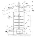
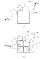
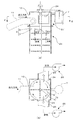
図1は、第1実施形態に係る土砂の破砕混合装置を示した鉛直断面図、図2は、A−A線及びB−B線に沿う水平断面図である。これらの図でわかるように、本実施形態に係る土砂の破砕混合装置1は、角筒体2a,円筒体2b及び角筒体2cをそれらの各内部空間が一体となるように下から順に積み重ねることで処理容器2として一つの筒体を構成してあるとともに、該処理容器の内部空間に衝撃付与機構3を配置してある。
(First embodiment)
FIG. 1 is a vertical sectional view showing the earth and sand crushing and mixing apparatus according to the first embodiment, and FIG. 2 is a horizontal sectional view taken along lines AA and BB. As can be seen from these figures, the earth and sand crushing and mixing
衝撃付与機構3は、材軸がほぼ鉛直になるようにかつ該材軸廻りに回転自在となるように処理容器2内に保持されたシャフト4と、該シャフトの周面に基端側が取り付けられた衝撃付与部材としての鋼製のチェーン5とで構成してあり、シャフト4を回転させることによって、チェーン5を該シャフトの材軸回りに旋回させ、該旋回範囲に自由落下する土砂に衝撃を付与することができるようになっている。
The
ここで、シャフト4は、角筒体2cの天板に設けられた軸受6を貫通して外側に延びた上方端部を角筒体2cの外周面に取り付けられたモータ7の回転軸に回転駆動機構8を介して連結してあるとともに、円筒体2bの下縁近傍に水平に設置されたスポーク状の軸受9で下方端部を回転自在に支持してある。
Here, the shaft 4 rotates on the rotating shaft of the
チェーン5は、シャフト4の周面に90゜ごとに取り付けられた4本を一組とし、かかる組を鉛直方向に沿った異なる高さごとに4段に設けた構成、本数で言えば計16本で構成してあり、シャフト4の静止時には、該シャフトから垂れ下がった状態であるが、モータ7を駆動してシャフト4を回転させると、該シャフトの材軸廻りに放射方向に延びた状態で旋回するようになっている。
The chain 5 is a set of four chains attached to the peripheral surface of the shaft 4 at 90 ° intervals, and such groups are provided in four stages at different heights along the vertical direction. When the shaft 4 is stationary, it is hung from the shaft, but when the
処理容器2のうち、最上段の角筒体2cの側板には土砂投入口10を形成してあり、該土砂投入口にベルトコンベヤ11の機首を挿入配置することにより、該ベルトコンベヤで搬送されてきた土砂を処理容器2内に投入できるようになっているとともに、最下段の角筒体2aの側板には土砂排出口12を形成してあり、該土砂排出口にベルトコンベヤ13の尾端を挿入配置することにより、処理が終わった土砂を処理容器2内から搬出できるようになっている。
Of the
ここで、最下段の角筒体2aの側板のうち、土砂排出口12が形成された側板と直交する側板には空気流入口21を形成してあるとともに、該空気流入口には、一端が送気ブロワ23に接続されたダクト22の他端を連通接続してあり、送気ブロワ23を作動させることで、送気ダクト22及び空気流入口21を介して角筒体2aの内部空間に空気を供給することができるようになっている。
Here, an
すなわち、送気ブロワ23及びダクト22は、衝撃付与機構3の下方位置に拡がる処理容器2の内部空間に空気を供給する送気手段として機能する。
That is, the
一方、最上段の角筒体2cの側板のうち、土砂投入口10が形成された側板と直交する側板には排気口24を形成してあるとともに、該排気口には、一端が吸気ブロワ26に接続されたダクト25の他端を連通接続してあり、吸気ブロワ26を作動させることで、排気口24及びダクト25を介して角筒体2cの内部空間から空気を吸引し、該内部空間から空気を排出することができるようになっている。
On the other hand, among the side plates of the uppermost
すなわち、吸気ブロワ26及びダクト25は、衝撃付与機構3の上方位置に拡がる処理容器2の内部空間から空気を排出する排気手段として機能する。
That is, the
本実施形態に係る土砂の破砕混合装置1を用いて土砂を破砕混合するには、モータ7でシャフト4を回転させることによりチェーン5を旋回させるとともに、かかる旋回動作中に土砂投入口10を介して処理容器2内に土砂を投入する。モータ7は、シャフト4の回転数が例えば500rpm程度となるように駆動すればよい。
In order to crush and mix the earth and sand using the earth and sand crushing and mixing
ベルトコンベヤ11を介して投入される土砂としては、典型的には、破砕混合同時処理を目的とした、固化材や活性炭が添加された土砂が対象となるが、破砕が主たる目的の場合には、例えば粒度調整を目的とした土砂が対象となり、混合が主たる目的の場合には、例えば破砕の程度が十分に進行した土砂であって固化材や活性炭が添加されたものが対象となる。
As the earth and sand thrown in via the
このような土砂をチェーン5を旋回させながら土砂投入口10を介して処理容器2内に投入すると、土砂は、チェーン5の旋回範囲に自然落下して該チェーンと接触し、そのときの衝撃で土砂がより小さな土塊へと破砕され、場合によってはその破砕時の飛散作用で不均質であった土砂がより均質な状態へと混合され、あるいは衝撃による土砂の飛散によってより均質な状態へと混合される。
When such earth and sand is thrown into the
また、シャフト4の回転によるチェーン5の旋回動作に加えて、送気ブロワ23及び吸気ブロワ26を同時に作動させる。
In addition to the turning operation of the chain 5 by the rotation of the shaft 4, the
このようにすると、衝撃付与機構3の下方位置には、ダクト22及び空気流入口21を介して空気が供給され、上方位置からは排気口24及びダクト25を介して空気が排出されるため、処理容器2の内部空間においては、下方から上方へと向かう空気の流れが形成される。
In this way, air is supplied to the lower position of the
ここで、処理容器2下方のみからの送風では、チェーン5の旋回動作によって空気流が遮断される懸念があるが、上述した構成によれば、チェーン5の旋回範囲においても、下方から上方への空気流を確実に形成することができる。
Here, when the air is blown only from below the
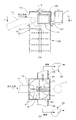
図3は、かかる空気の流れを白の矢印で、投入された土砂の落下方向を黒の矢印でそれぞれ示したものであり、同図でわかるように、上方へと向かう空気の流れは、土砂や土塊が落下する際の抵抗となり、それらの落下速度を低下させる。そのため、自然落下する土砂や土塊は、チェーン5から受ける衝撃回数が増加して十分な程度に破砕あるいは飛散し、結果としてより細かな破砕処理やより均質な混合処理が可能になる。 FIG. 3 shows the flow of air with a white arrow, and the falling direction of the introduced sediment with a black arrow. As can be seen in FIG. 3, the upward flow of air is And it becomes resistance when the earth lump falls, and those fall speeds are reduced. Therefore, the earth and sand that naturally fall and the number of impacts received from the chain 5 are increased and crushed or scattered to a sufficient extent, and as a result, a finer crushing process and a more homogeneous mixing process are possible.
チェーン5による衝撃付与及び空気流による衝突という2つの作用を受けた土砂あるいは土塊は、より細かく破砕されあるいはより均質に混合された状態でベルトコンベヤ13上に落下し、該ベルトコンベヤにより、土砂排出口12を介して処理容器2内から回収される。
The earth or sand lump subjected to the two effects of the impact imparted by the chain 5 and the collision by the air flow falls on the
回収された土については、必要に応じて上述のプロセスを繰り返し行うことで、破砕や混合の程度を高めた上、ダンプトラックに積載し、廃棄物処分場や再利用場所まで運搬する。 The collected soil is repeatedly carried out as necessary to increase the degree of crushing and mixing, and then loaded onto a dump truck and transported to a waste disposal site or a reuse site.
以上説明したように、本実施形態に係る土砂の破砕混合装置1によれば、シャフト4の回転によるチェーン5の旋回動作に加え、送気ブロワ23及び吸気ブロワ26によって処理容器2の内部空間に下方から上方へと向かう空気流を形成するようにしたので、投入された土砂や土塊の落下速度は上方への空気流による抵抗で低下する。
As described above, according to the earth and sand crushing and mixing
そのため、チェーン5から投入土砂に付与される衝撃の回数が増加することとなり、かくして投入土砂は、十分に破砕されてより細かな破砕処理が可能になり、あるいは十分に飛散することで、高い均質性をもった混合処理が可能になる。 Therefore, the number of impacts applied to the input soil from the chain 5 is increased, and thus the input soil is sufficiently crushed so that it can be finely crushed or is sufficiently scattered, so that it is highly homogeneous. The mixing process with the characteristic becomes possible.
また、本実施形態に係る土砂の破砕混合装置1によれば、送気手段であるダクト22及び送気ブロワ23を空気流入口21に接続することで、衝撃付与機構3の下方位置に拡がる処理容器2の内部空間に空気を供給するようにしたので、処理容器2内において下方から上方へと向かう空気流を確実に形成することが可能となる。
Moreover, according to the earth and sand crushing and mixing
また、本実施形態に係る土砂の破砕混合装置1によれば、排気口24を土砂投入口10の正面ではなく、側面に形成したので、排気口24を介した吸引力が土砂投入口10に直接作用することがなくなり、投入土砂が排気口24に直接吸引されるおそれはない。
Moreover, according to the earth and sand crushing and mixing
本実施形態では、チェーン5で衝撃付与部材を構成したが、チェーン5に代えて、例えばロッド材、鋼線、羽根材等でもかまわないし、自然落下する土砂に物理的な衝撃を加えることができるのであれば、衝撃付与部材の構成や形態は任意である。 In the present embodiment, the impact imparting member is configured by the chain 5, but instead of the chain 5, for example, a rod material, a steel wire, a blade material, or the like may be used, and a physical impact can be applied to the naturally falling earth and sand. If it is, the structure and form of an impact provision member are arbitrary.
また、本実施形態では、角筒体2a,円筒体2b及び角筒体2cで処理容器2を構成するようにしたが、このような別体組立に代えて、一体構成とすることはもちろん可能であるし、円筒や角筒といった断面形状は一例であって、任意の断面形状を採用できることは言うまでもない。
Further, in the present embodiment, the
(第2実施形態)
次に、第2実施形態について説明する。なお、第1実施形態と実質的に同一の部品等については同一の符号を付してその説明を省略する。
(Second Embodiment)
Next, a second embodiment will be described. Note that components that are substantially the same as those of the first embodiment are denoted by the same reference numerals, and description thereof is omitted.
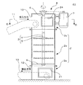
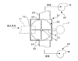
図4は、第2実施形態に係る土砂の破砕混合装置を示した鉛直断面図、図5は、D−D線に沿う水平断面図である。これらの図でわかるように、本実施形態に係る土砂の破砕混合装置41は、角筒体2a,円筒体2b及び角筒体2c′をそれらの各内部空間が一体となるように下から順に積み重ねることで処理容器2′として一つの筒体を構成してあるとともに、該処理容器の内部空間に衝撃付与機構3を配置してある。
FIG. 4 is a vertical sectional view showing the earth and sand crushing and mixing apparatus according to the second embodiment, and FIG. 5 is a horizontal sectional view taken along the line DD. As can be seen from these drawings, the earth and sand crushing and mixing
処理容器2′のうち、最下段の角筒体2aの側板には第1実施形態と同様、土砂排出口12を形成してあり、該土砂排出口にベルトコンベヤ13の尾端を挿入配置することにより、処理が終わった土砂を処理容器2内から搬出できるようになっているとともに、土砂排出口12が形成された側板と直交する側板には空気流入口21を形成してある。
As in the first embodiment, a
空気流入口21には第1実施形態と同様、ダクト22を介して送気ブロワ23を連通接続してあり(図2(a)参照)、該送気ブロワを作動させることによって角筒体2aの内部空間に空気を供給することができるようになっている。すなわち、送気ブロワ23及びダクト22は、衝撃付与機構3の下方位置に拡がる処理容器2′の内部空間に空気を供給する送気手段として機能する。
As in the first embodiment, an
一方、処理容器2′のうち、最上段の角筒体2c′は図5に示したように、その側板に土砂投入口10を形成してあり、該土砂投入口にベルトコンベヤ11の機首を挿入配置することにより、該ベルトコンベヤで搬送されてきた土砂を処理容器2′内に投入できるようになっていることに加え、側板のうち、土砂投入口10が形成された側板と直交する対向側板には、排気口24,24をそれぞれ形成してあるとともに、該各排気口には、ダクト25を介して吸気ブロワ26をそれぞれ連通接続してあり、吸気ブロワ26,26を作動させることで、排気口24,24及びダクト25,25を介して角筒体2c′の内部空間から空気を吸引し、該内部空間から空気を排出することができるようになっているとともに、吸気ブロワ26,26の流量を送気ブロワ23の流量よりも大きく設定できるように構成してある。
On the other hand, as shown in FIG. 5, the topmost
すなわち、吸気ブロワ26,26及びダクト25,25は、衝撃付与機構3の上方位置に拡がる処理容器2′の内部空間から空気を排出する排気手段として機能するとともに、送気ブロワ23及びダクト22からなる送気手段と協働し、かつ該送気手段による送気流量よりも排気流量を大きくすることで、処理容器2′内において下方から上方へ向かう空気流をより確実に形成することを可能にする。
That is, the
なお、衝撃付与機構3は第1実施形態と概ね同様であるが、第2実施形態においては、シャフト4の上方端部を、角筒体2c′の天板に設けられた軸受6に貫通させた上、角筒体2c′の外周面に取り付けられたモータ7の回転軸に回転駆動機構8を介して連結してある。
The
本実施形態に係る土砂の破砕混合装置41を用いて土砂を破砕混合するには第1実施形態と同様、モータ7でシャフト4を回転させることによりチェーン5を旋回させるとともに、かかる旋回動作中に土砂投入口10を介して処理容器2′内に土砂を投入することで、土砂をチェーン5の旋回範囲に自然落下させて該チェーンと接触させ、土砂の破砕混合を行う。
In order to crush and mix the earth and sand using the earth and sand crushing and mixing
一方、このようなシャフト4の回転によるチェーン5の旋回動作に加えて、送気ブロワ23及び吸気ブロワ26,26を同時に作動させる。
On the other hand, in addition to the turning operation of the chain 5 by the rotation of the shaft 4, the
このようにすると、衝撃付与機構3の下方位置には、ダクト22及び空気流入口21を介して空気が供給され、上方位置からは排気口24,24及びダクト25,25を介してかつ送気流量よりも大きな排気流量で空気が排出されるため、処理容器2′の内部空間、特にチェーン5の旋回範囲においては、チェーン5による旋回方向の空気流にかかわらず、下方から上方へと向かう空気の流れが確実に形成される。
If it does in this way, air will be supplied to the lower position of the
図6は、上方へ向かう空気流を白の矢印で、投入された土砂の落下方向を黒の矢印でそれぞれ示したものであり、同図でわかるように、上方へと向かう空気の流れは、土砂や土塊が落下する際の抵抗となり、それらの落下速度を低下させる。そのため、自然落下する土砂や土塊は、チェーン5から受ける衝撃回数が増加して十分な程度に破砕あるいは飛散し、結果としてより細かな破砕処理やより均質な混合処理が可能になる。 In FIG. 6, the upward air flow is indicated by white arrows, and the falling direction of the introduced earth and sand is indicated by black arrows. As can be seen from the figure, the upward air flow is: It becomes resistance when earth and sand and a lump fall, and those fall speeds are reduced. Therefore, the earth and sand that naturally fall and the number of impacts received from the chain 5 are increased and crushed or scattered to a sufficient extent, and as a result, a finer crushing process and a more homogeneous mixing process are possible.
チェーン5による衝撃付与及び空気流による衝突という2つの作用を受けた土砂あるいは土塊は、より細かく破砕されあるいはより均質に混合された状態でベルトコンベヤ13上に落下し、該ベルトコンベヤにより、土砂排出口12を介して処理容器2内から回収される。
The earth or sand lump subjected to the two effects of the impact imparted by the chain 5 and the collision by the air flow falls on the
回収された土については、必要に応じて上述のプロセスを繰り返し行うことで、破砕や混合の程度を高めた上、ダンプトラックに積載し、廃棄物処分場や再利用場所まで運搬する。 The collected soil is repeatedly carried out as necessary to increase the degree of crushing and mixing, and then loaded onto a dump truck and transported to a waste disposal site or a reuse site.
以上説明したように、本実施形態に係る土砂の破砕混合装置41及びそれを用いた方法によれば、シャフト4の回転によるチェーン5の旋回動作に加え、送気ブロワ23及び吸気ブロワ26,26によって処理容器2の内部空間に下方から上方へと向かう空気流を形成するようにしたので、投入された土砂や土塊の落下速度は上方への空気流による抵抗で低下する。
As described above, according to the earth and sand crushing and mixing
そのため、チェーン5から投入土砂に付与される衝撃の回数が増加することとなり、かくして投入土砂は、十分に破砕されてより細かな破砕処理が可能になり、あるいは十分に飛散することで、高い均質性をもった混合処理が可能になる。 Therefore, the number of impacts applied to the input soil from the chain 5 is increased, and thus the input soil is sufficiently crushed so that it can be finely crushed or is sufficiently scattered, so that it is highly homogeneous. The mixing process with the characteristic becomes possible.
また、本実施形態に係る土砂の破砕混合装置1によれば、送気手段であるダクト22及び送気ブロワ23を空気流入口21に接続することで、衝撃付与機構3の下方位置に拡がる処理容器2の内部空間に空気を供給するようにしたので、処理容器2内において下方から上方へと向かう空気流を確実に形成することが可能となる。
Moreover, according to the earth and sand crushing and mixing
また、本実施形態に係る土砂の破砕混合装置1によれば、排気口24,24を土砂投入口10の正面ではなく、側面に形成したので、排気口24,24を介した吸引力が土砂投入口10に直接作用することがなくなり、投入土砂が排気口24,24に直接吸引されるおそれはない。
Moreover, according to the earth and sand crushing and mixing
また、本実施形態に係る土砂の破砕混合装置41によれば、吸気ブロワ26,26、ダクト25,25及び排気口24,24の二組構成で排気手段を構成するとともに、排気流量が送気流量よりも大きくなるように設定したので、処理容器2′内においては、下方から上方への空気流が確実に形成され、かくして上述した作用効果がより確実に発揮される。
Moreover, according to the earth and sand crushing and mixing
また、本実施形態に係る土砂の破砕混合装置41によれば、排気流量が送気流量よりも大きくなるように設定したことによって処理容器2′内が負圧となり、該処理容器内で発生した粉塵が大気に放出されるのを未然に防止することが可能となる。
Moreover, according to the earth and sand crushing and mixing
本実施形態では特に言及しなかったが、排気口24,24を対面配置したことにより、それらを介した吸気ブロワ26,26の吸引力が相殺し合う懸念がある場合には、図7に示すように、一対の仕切板71,71を、それぞれが排気口24,24に対向するようにかつ互いにシャフト4の反対側に位置するようにチェーン5の上方に配置すればよい。
Although not particularly mentioned in the present embodiment, when there is a concern that the suction forces of the
かかる構成によれば、吸気ブロワ26,26の吸引力が相殺し合う懸念がなくなり、吸気ブロワ26,26、ダクト25,25及び排気口24,24の2組構成からなる排気手段の能力をいかんなく発揮させることが可能となる。
According to such a configuration, there is no concern that the suction forces of the
排気口24,24を対面配置したことによる吸気ブロワ26,26の吸引力低下を防止する別の構成として、図8に示すように、チェーン5の配置空間を通過した空気の流れが2方向に分岐しそれぞれが一対の排気口24,24に向けて案内されるように、チェーン5の上方に三角形断面をなすガイド部材81,81を配置するようにしてもよい。
As another configuration for preventing the suction force of the
ガイド部材81,81は、それらの材軸が水平になるように、かつ底面が横向きとなってシャフト4を向いた背中合わせとなるように配置してあり、上縁に向けて延びる斜面によって土砂投入口10から投入された土砂が滑落して堆積が防止されるとともに、下縁に向けて延びる斜面によってチェーン5の配置空間を通過した空気の流れが2方向に分岐するようになっている。
The
かかる構成によれば、吸気ブロワ26,26の吸引力が相殺し合う懸念がなくなり、吸気ブロワ26,26、ダクト25,25及び排気口24,24の2組構成からなる排気手段の能力をいかんなく発揮させることが可能となる。
According to such a configuration, there is no concern that the suction forces of the
1,41 土砂の破砕混合装置
2,2′ 処理容器
3 衝撃付与機構
4 シャフト
5 チェーン(衝撃付与部材)
10 土砂投入口
12 土砂排出口
21 空気流入口
24 排気口
71 仕切板
81 ガイド部材
DESCRIPTION OF
DESCRIPTION OF
Claims (9)
前記衝撃付与部材を旋回させながら、前記衝撃付与部材の上方位置に拡がる前記処理容器の内部空間からの空気排出を行うことを特徴とする土砂の破砕混合方法。 By introducing earth and sand from the earth and sand inlet formed above the processing container, and operating the impact applying mechanism arranged in the processing container to rotate the shaft constituting it around a substantially vertical axis The impact applying member having the base end attached to the peripheral surface of the shaft is swung in a horizontal plane, and the earth and sand introduced through the earth and sand introducing port is naturally dropped into the swiveling range of the impact applying member, A method for crushing and mixing earth and sand to crush the earth and sand and carry it out through an earth and sand outlet formed below the processing container,
A method for crushing and mixing earth and sand, wherein air is discharged from the internal space of the processing container that extends to a position above the impact applying member while the impact applying member is swung.
Priority Applications (1)
| Application Number | Priority Date | Filing Date | Title |
|---|---|---|---|
| JP2011063370A JP5692645B2 (en) | 2011-03-22 | 2011-03-22 | Earth and sand crushing and mixing apparatus and method using the same |
Applications Claiming Priority (1)
| Application Number | Priority Date | Filing Date | Title |
|---|---|---|---|
| JP2011063370A JP5692645B2 (en) | 2011-03-22 | 2011-03-22 | Earth and sand crushing and mixing apparatus and method using the same |
Publications (2)
| Publication Number | Publication Date |
|---|---|
| JP2012196639A true JP2012196639A (en) | 2012-10-18 |
| JP5692645B2 JP5692645B2 (en) | 2015-04-01 |
Family
ID=47179408
Family Applications (1)
| Application Number | Title | Priority Date | Filing Date |
|---|---|---|---|
| JP2011063370A Active JP5692645B2 (en) | 2011-03-22 | 2011-03-22 | Earth and sand crushing and mixing apparatus and method using the same |
Country Status (1)
| Country | Link |
|---|---|
| JP (1) | JP5692645B2 (en) |
Cited By (3)
| Publication number | Priority date | Publication date | Assignee | Title |
|---|---|---|---|---|
| CN104190501A (en) * | 2014-07-11 | 2014-12-10 | 同济大学 | Free single-chain crusher |
| CN107593879A (en) * | 2017-09-26 | 2018-01-19 | 胡鑫海 | A kind of preservation of fishery stirs salting apparatus with automatic blanking |
| CN112774819A (en) * | 2020-12-30 | 2021-05-11 | 鹤岗市田丰农机制造有限公司 | Axial crushing and rubbing machine |
Citations (4)
| Publication number | Priority date | Publication date | Assignee | Title |
|---|---|---|---|---|
| JP2000325887A (en) * | 1999-05-21 | 2000-11-28 | Ishikawajima Harima Heavy Ind Co Ltd | Miscellaneous waste sorting equipment |
| JP2001124474A (en) * | 1999-10-28 | 2001-05-11 | Kumakura Industry Co Ltd | Dryer |
| JP3554829B2 (en) * | 1997-03-27 | 2004-08-18 | 日本国土開発株式会社 | Soil material production equipment |
| JP2005193087A (en) * | 2003-12-26 | 2005-07-21 | Jdc Corp | Rotating levitation hitting processing method and rotating levitation hitting processing apparatus |
-
2011
- 2011-03-22 JP JP2011063370A patent/JP5692645B2/en active Active
Patent Citations (4)
| Publication number | Priority date | Publication date | Assignee | Title |
|---|---|---|---|---|
| JP3554829B2 (en) * | 1997-03-27 | 2004-08-18 | 日本国土開発株式会社 | Soil material production equipment |
| JP2000325887A (en) * | 1999-05-21 | 2000-11-28 | Ishikawajima Harima Heavy Ind Co Ltd | Miscellaneous waste sorting equipment |
| JP2001124474A (en) * | 1999-10-28 | 2001-05-11 | Kumakura Industry Co Ltd | Dryer |
| JP2005193087A (en) * | 2003-12-26 | 2005-07-21 | Jdc Corp | Rotating levitation hitting processing method and rotating levitation hitting processing apparatus |
Cited By (4)
| Publication number | Priority date | Publication date | Assignee | Title |
|---|---|---|---|---|
| CN104190501A (en) * | 2014-07-11 | 2014-12-10 | 同济大学 | Free single-chain crusher |
| CN107593879A (en) * | 2017-09-26 | 2018-01-19 | 胡鑫海 | A kind of preservation of fishery stirs salting apparatus with automatic blanking |
| CN107593879B (en) * | 2017-09-26 | 2020-12-15 | 乐安县恒源食品有限公司 | An automatic feeding, stirring and pickling device for aquatic product preservation |
| CN112774819A (en) * | 2020-12-30 | 2021-05-11 | 鹤岗市田丰农机制造有限公司 | Axial crushing and rubbing machine |
Also Published As
| Publication number | Publication date |
|---|---|
| JP5692645B2 (en) | 2015-04-01 |
Similar Documents
| Publication | Publication Date | Title |
|---|---|---|
| JP5692646B2 (en) | Sediment crushing and mixing equipment | |
| CN104053506B (en) | Method of operating an agitator ball mill and agitator ball mill for performing the method | |
| JP5692645B2 (en) | Earth and sand crushing and mixing apparatus and method using the same | |
| JP6346883B2 (en) | Soil improvement equipment | |
| CN101918141B (en) | Roller mill for grinding particulate material | |
| CN108655163A (en) | A kind of contaminated soil processing unit | |
| JP2003071426A (en) | Self-propelled contaminated soil treatment machine, contaminated soil treatment system and contaminated soil treatment method | |
| US20200009518A1 (en) | Mixer/vacuum coater | |
| CN105056796A (en) | Chemical raw material stirring device and method | |
| KR102293348B1 (en) | Recycled soil treatment devices and methods to reduce dust and odour, waste removal during the intermediate process of construction waste | |
| CN106671276A (en) | Dust removal type concrete mixing plant | |
| JP2003340425A (en) | Contaminated soil treatment system and contaminated soil treatment method | |
| WO2021261217A1 (en) | Rotary processing device | |
| JP4768316B2 (en) | Soil crusher | |
| RU2532432C2 (en) | Method of loose material mixing and mixer to this end | |
| JPH1086135A (en) | Steel fiber loading device and concrete casting hopper in concrete kneader | |
| JP4078561B2 (en) | Resin fiber feeder | |
| CN113398826A (en) | Powdery new material injection formula mixing apparatus | |
| JP2002307426A (en) | Material supply machine for resin concrete pipe production | |
| CN207745789U (en) | Medicinal powder mixing apparatus | |
| CN112808134A (en) | Flue gas desulfurization, denitrification and purification treatment process | |
| JP3955422B2 (en) | Mud solidification processing equipment | |
| CN118788736A (en) | Soil remediation washing device and soil remediation method | |
| CN209238674U (en) | A kind of dystopy soil remediation equipment | |
| US4973166A (en) | Particulate material conditioner |
Legal Events
| Date | Code | Title | Description |
|---|---|---|---|
| A621 | Written request for application examination |
Free format text: JAPANESE INTERMEDIATE CODE: A621 Effective date: 20140222 |
|
| TRDD | Decision of grant or rejection written | ||
| A01 | Written decision to grant a patent or to grant a registration (utility model) |
Free format text: JAPANESE INTERMEDIATE CODE: A01 Effective date: 20150109 |
|
| A61 | First payment of annual fees (during grant procedure) |
Free format text: JAPANESE INTERMEDIATE CODE: A61 Effective date: 20150122 |
|
| R150 | Certificate of patent or registration of utility model |
Ref document number: 5692645 Country of ref document: JP Free format text: JAPANESE INTERMEDIATE CODE: R150 |