JP2012197770A - Internal combustion engine with variable compression ratio mechanism - Google Patents
Internal combustion engine with variable compression ratio mechanism Download PDFInfo
- Publication number
- JP2012197770A JP2012197770A JP2011063852A JP2011063852A JP2012197770A JP 2012197770 A JP2012197770 A JP 2012197770A JP 2011063852 A JP2011063852 A JP 2011063852A JP 2011063852 A JP2011063852 A JP 2011063852A JP 2012197770 A JP2012197770 A JP 2012197770A
- Authority
- JP
- Japan
- Prior art keywords
- timing
- compression ratio
- intake valve
- valve
- knocking
- Prior art date
- Legal status (The legal status is an assumption and is not a legal conclusion. Google has not performed a legal analysis and makes no representation as to the accuracy of the status listed.)
- Withdrawn
Links
Images






Classifications
-
- Y—GENERAL TAGGING OF NEW TECHNOLOGICAL DEVELOPMENTS; GENERAL TAGGING OF CROSS-SECTIONAL TECHNOLOGIES SPANNING OVER SEVERAL SECTIONS OF THE IPC; TECHNICAL SUBJECTS COVERED BY FORMER USPC CROSS-REFERENCE ART COLLECTIONS [XRACs] AND DIGESTS
- Y02—TECHNOLOGIES OR APPLICATIONS FOR MITIGATION OR ADAPTATION AGAINST CLIMATE CHANGE
- Y02T—CLIMATE CHANGE MITIGATION TECHNOLOGIES RELATED TO TRANSPORTATION
- Y02T10/00—Road transport of goods or passengers
- Y02T10/10—Internal combustion engine [ICE] based vehicles
- Y02T10/12—Improving ICE efficiencies
-
- Y—GENERAL TAGGING OF NEW TECHNOLOGICAL DEVELOPMENTS; GENERAL TAGGING OF CROSS-SECTIONAL TECHNOLOGIES SPANNING OVER SEVERAL SECTIONS OF THE IPC; TECHNICAL SUBJECTS COVERED BY FORMER USPC CROSS-REFERENCE ART COLLECTIONS [XRACs] AND DIGESTS
- Y02—TECHNOLOGIES OR APPLICATIONS FOR MITIGATION OR ADAPTATION AGAINST CLIMATE CHANGE
- Y02T—CLIMATE CHANGE MITIGATION TECHNOLOGIES RELATED TO TRANSPORTATION
- Y02T10/00—Road transport of goods or passengers
- Y02T10/10—Internal combustion engine [ICE] based vehicles
- Y02T10/40—Engine management systems
Landscapes
- Output Control And Ontrol Of Special Type Engine (AREA)
- Electrical Control Of Air Or Fuel Supplied To Internal-Combustion Engine (AREA)
- Electrical Control Of Ignition Timing (AREA)
Abstract
Description
本発明は、可変圧縮比機構を備える内燃機関に関する。 The present invention relates to an internal combustion engine including a variable compression ratio mechanism.
可変圧縮比機構により機械圧縮比を可変とする内燃機関が公知である。このような内燃機関において、推定された実圧縮比が目標実圧縮比より高くなるときには、点火時期を遅角してノッキングの発生を抑制することが提案されている(特許文献1参照)。 An internal combustion engine in which the mechanical compression ratio is variable by a variable compression ratio mechanism is known. In such an internal combustion engine, when the estimated actual compression ratio becomes higher than the target actual compression ratio, it has been proposed to retard the ignition timing to suppress the occurrence of knocking (see Patent Document 1).
確かに、実圧縮比が目標実圧縮比より高ければ、目標実圧縮比に対して設定された点火時期に対してノッキングが発生し易くなる。しかしながら、ノッキングが発生するか否かは、燃焼しないとした場合の圧縮上死点における推定気筒内圧力、すなわち、圧縮端圧力に基づく方が正確に判断することができる。例えば、吸気弁閉弁時の筒内圧力が通常より高ければ、目標実圧縮比が実現されても、圧縮端圧力は高くなり、目標実圧縮比に対して定められた点火時期に対してノッキングが発生することがある。 Certainly, if the actual compression ratio is higher than the target actual compression ratio, knocking is likely to occur at the ignition timing set for the target actual compression ratio. However, whether or not knocking occurs can be more accurately determined based on the estimated in-cylinder pressure at the compression top dead center when the combustion is not performed, that is, the compression end pressure. For example, if the in-cylinder pressure when the intake valve is closed is higher than normal, the compression end pressure will be high even if the target actual compression ratio is realized, and knocking will be performed with respect to the ignition timing determined for the target actual compression ratio May occur.
圧縮端圧力は、実圧縮比だけでなく吸気弁閉弁時の筒内圧力によっても変化するために、吸気弁の実際の閉弁時期とならなければ、正確に推定することはできない。それにより、吸気弁の閉弁時期を変化させる内燃機関において、吸気弁の閉弁時期が点火時期の設定時期以降となると、点火時期の設定時期では正確な圧縮端圧力を推定することはできず、設定された点火時期ではノッキングが発生してしまうことがある。 Since the compression end pressure changes not only with the actual compression ratio but also with the in-cylinder pressure when the intake valve is closed, it cannot be accurately estimated unless the actual valve closing timing of the intake valve is reached. As a result, in an internal combustion engine that changes the closing timing of the intake valve, if the closing timing of the intake valve is after the ignition timing setting timing, the accurate compression end pressure cannot be estimated at the ignition timing setting timing. In some cases, knocking may occur at the set ignition timing.
従って、本発明の目的は、可変圧縮比機構を備える内燃機関において、吸気弁の閉弁時期が点火時期の設定時期以降である場合においても、ノッキングの発生を抑制可能とすることである。 Therefore, an object of the present invention is to make it possible to suppress the occurrence of knocking in an internal combustion engine having a variable compression ratio mechanism even when the intake valve closing timing is after the ignition timing setting timing.
本発明による請求項1に記載の可変圧縮比機構を備える内燃機関は、可変圧縮比機構を備える内燃機関であって、可変バルブタイミング機構により制御される吸気弁の閉弁時期が点火時期の設定時期より前であるときには、吸気弁の閉弁時期以降に推定される圧縮端圧力に対してノッキングを発生させない点火時期を前記設定時期において設定し、前記可変バルブタイミング機構により制御される吸気弁の閉弁時期が点火時期の前記設定時期以降であるときには、吸気弁の閉弁時期以降に推定される圧縮端圧力に対して前記設定時期において設定された点火時期ではノッキングが発生すると予測される場合に、前記可変圧縮比機構により機械圧縮比を低下させることを特徴とする。 An internal combustion engine having a variable compression ratio mechanism according to a first aspect of the present invention is an internal combustion engine having a variable compression ratio mechanism, wherein the closing timing of the intake valve controlled by the variable valve timing mechanism is set to the ignition timing. If it is before the timing, an ignition timing that does not cause knocking to the compression end pressure estimated after the closing timing of the intake valve is set at the set timing, and the intake valve controlled by the variable valve timing mechanism is set. When the closing timing is after the set timing of the ignition timing, when knocking is predicted to occur at the ignition timing set at the set timing with respect to the compression end pressure estimated after the closing timing of the intake valve Further, the mechanical compression ratio is lowered by the variable compression ratio mechanism.
本発明による請求項2に記載の可変圧縮比機構を備える内燃機関は、請求項1に記載の可変圧縮比機構を備える内燃機関において、前記内燃機関は燃料を気筒内へ直接的に噴射する燃料噴射弁を具備し、前記可変バルブタイミング機構により制御される吸気弁の閉弁時期が点火時期の前記設定時期以降であるときに、吸気弁の閉弁時期以降に推定される圧縮端圧力に対して前記設定時期において設定された点火時期ではノッキングが発生すると予測される場合には、さらに前記燃料噴射弁により追加燃料を供給することを特徴とする。 An internal combustion engine having the variable compression ratio mechanism according to claim 2 according to the present invention is an internal combustion engine having the variable compression ratio mechanism according to claim 1, wherein the internal combustion engine directly injects fuel into a cylinder. When the intake valve closing timing controlled by the variable valve timing mechanism is after the set timing of the ignition timing, the compression end pressure estimated after the intake valve closing timing is provided. In the case where it is predicted that knocking will occur at the ignition timing set at the set timing, additional fuel is further supplied by the fuel injection valve.
本発明による請求項1に記載の可変圧縮比機構を備える内燃機関によれば、可変バルブタイミング機構により制御される吸気弁の閉弁時期が点火時期の設定時期より前であるときには、吸気弁の閉弁時期以降に推定される正確な圧縮端圧力に対してノッキングを発生させない点火時期を設定時期において設定することにより、ノッキングの発生を抑制することができる。また、可変バルブタイミング機構により制御される吸気弁の閉弁時期が点火時期の設定時期以降であるときには、吸気弁の閉弁時期以降に推定される正確な圧縮端圧力に対して設定時期において設定された点火時期ではノッキングが発生すると予測される場合に可変圧縮比機構により機械圧縮比を低下させるようになっている。それにより、実際の圧縮端圧力を低下させることができ、ノッキングの発生を抑制することができる。可変バルブタイミング機構により制御される吸気弁の閉弁時期が点火時期の設定時期より前であるときにも、吸気弁の閉弁時期以降に推定される正確な圧縮端圧力に対して設定時期において設定される点火時期ではノッキングが発生すると予測される場合に可変圧縮比機構により機械圧縮比を低下させてノッキングの発生を抑制することも可能であるが、点火時期制御に比較して可変圧縮比機構を作動させると、多量の電気エネルギーを消費することとなるために、このときには、点火時期制御によりノッキングの発生を抑制する方が好ましい。 According to the internal combustion engine including the variable compression ratio mechanism according to the first aspect of the present invention, when the closing timing of the intake valve controlled by the variable valve timing mechanism is earlier than the set timing of the ignition timing, The occurrence of knocking can be suppressed by setting the ignition timing at which the knocking is not generated for the accurate compression end pressure estimated after the valve closing time at the set time. Also, when the intake valve closing timing controlled by the variable valve timing mechanism is after the ignition timing setting timing, it is set at the setting timing with respect to the accurate compression end pressure estimated after the intake valve closing timing. When knocking is predicted to occur at the ignition timing, the mechanical compression ratio is lowered by the variable compression ratio mechanism. Thereby, an actual compression end pressure can be reduced and the occurrence of knocking can be suppressed. Even when the closing timing of the intake valve controlled by the variable valve timing mechanism is earlier than the setting timing of the ignition timing, at the set timing with respect to the accurate compression end pressure estimated after the closing timing of the intake valve When knocking is predicted to occur at the set ignition timing, the mechanical compression ratio can be reduced by the variable compression ratio mechanism to suppress the occurrence of knocking, but the variable compression ratio can be suppressed compared to ignition timing control. When the mechanism is operated, a large amount of electric energy is consumed. At this time, it is preferable to suppress the occurrence of knocking by controlling the ignition timing.
本発明による請求項2に記載の可変圧縮比機構を備える内燃機関によれば、請求項1に記載の可変圧縮比機構を備える内燃機関において、内燃機関は燃料を気筒内へ直接的に噴射する燃料噴射弁を具備し、可変バルブタイミング機構による吸気弁の閉弁時期が点火時期の設定時期以降であるときに、吸気弁の閉弁時期以降に推定される圧縮端圧力に対して設定時期において設定された点火時期ではノッキングが発生すると予測される場合には、さらに燃料噴射弁により追加燃料を供給するようになっており、追加燃料の気化潜熱により点火時期での筒内温度を低下させることができ、さらにノッキングの発生を抑制することができる。 According to the internal combustion engine including the variable compression ratio mechanism according to claim 2 of the present invention, in the internal combustion engine including the variable compression ratio mechanism according to claim 1, the internal combustion engine directly injects fuel into the cylinder. The fuel injection valve is provided, and when the intake valve closing timing by the variable valve timing mechanism is after the ignition timing setting timing, the compression end pressure estimated after the intake valve closing timing is set at the setting timing. If knocking is predicted to occur at the set ignition timing, additional fuel is supplied by the fuel injection valve, and the in-cylinder temperature at the ignition timing is reduced by the latent heat of vaporization of the additional fuel. And the occurrence of knocking can be suppressed.
図1は本発明による可変圧縮比機構を備える内燃機関の側面断面図を示す。図1を参照すると、1はクランクケース、2はシリンダブロック、3はシリンダヘッド、4はピストン、5は燃焼室、6は燃焼室5の頂面中央部に配置された点火栓、7は吸気弁、8は吸気ポート、9は排気弁、10は排気ポートを夫々示す。吸気ポート8は吸気枝管11を介してサージタンク12に連結される。13は各燃焼室5内へ直接的に燃料を噴射するための燃料噴射弁である。燃料噴射弁13は、各吸気枝管11に取り付けられることもある。
FIG. 1 is a side sectional view of an internal combustion engine having a variable compression ratio mechanism according to the present invention. Referring to FIG. 1, 1 is a crankcase, 2 is a cylinder block, 3 is a cylinder head, 4 is a piston, 5 is a combustion chamber, 6 is a spark plug disposed at the center of the top surface of the
サージタンク12は吸気ダクト14を介してエアクリーナ15に連結され、吸気ダクト14内にはアクチュエータ16によって駆動されるスロットル弁17と例えば熱線を用いた吸入空気量検出器18とが配置される。一方、排気ポート10は排気マニホルド19を介して例えば三元触媒を内蔵した触媒装置20に連結され、排気マニホルド19内には空燃比センサ21が配置される。
The
一方、図1に示される実施例ではクランクケース1とシリンダブロック2との連結部にクランクケース1とシリンダブロック2のシリンダ軸線方向の相対位置を変化させることによりピストン4が圧縮上死点に位置するときの燃焼室5の容積を変更可能な可変圧縮比機構Aが設けられており、更に実際の圧縮作用の開始時期を変更可能な実圧縮作用開始時期変更機構Bが設けられている。なお、図1に示される実施例ではこの実圧縮作用開始時期変更機構Bは吸気弁7の閉弁時期を制御可能な可変バルブタイミング機構からなる。
On the other hand, in the embodiment shown in FIG. 1, the
図1に示されるようにクランクケース1とシリンダブロック2にはクランクケース1とシリンダブロック2間の相対位置関係を検出するための相対位置センサ22が取付けられており、この相対位置センサ22からはクランクケース1とシリンダブロック2との間隔の変化を示す出力信号が出力される。また、可変バルブタイミング機構Bには吸気弁7の閉弁時期を示す出力信号を発生するバルブタイミングセンサ23が取付けられており、スロットル弁駆動用のアクチュエータ16にはスロットル弁開度を示す出力信号を発生するスロットル開度センサ24が取付けられている。
As shown in FIG. 1, a
電子制御ユニット30はデジタルコンピュータからなり、双方向性バス31によって互いに接続されたROM(リードオンリメモリ)32、RAM(ランダムアクセスメモリ)33、CPU(マイクロプロセッサ)34、入力ポート35および出力ポート36を具備する。吸入空気量検出器18、空燃比センサ21、相対位置センサ22、バルブタイミングセンサ23およびスロットル開度センサ24の出力信号は夫々対応するAD変換器37を介して入力ポート35に入力される。また、アクセルペダル40にはアクセルペダル40の踏込み量Lに比例した出力電圧を発生する負荷センサ41が接続され、負荷センサ41の出力電圧は対応するAD変換器37を介して入力ポート35に入力される。更に入力ポート35にはクランクシャフトが例えば30°回転する毎に出力パルスを発生するクランク角センサ42が接続される。一方、出力ポート36は対応する駆動回路38を介して点火栓6、燃料噴射弁13、スロットル弁駆動用アクチュエータ16、可変圧縮比機構Aおよび可変バルブタイミング機構Bに接続される。
The
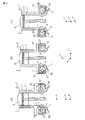
図2は図1に示す可変圧縮比機構Aの分解斜視図を示しており、図3は図解的に表した内燃機関の側面断面図を示している。図2を参照すると、シリンダブロック2の両側壁の下方には互いに間隔を隔てた複数個の突出部50、すなわち、シリンダブロック側サポートが形成されており、各突出部50内には夫々断面円形のカム挿入孔51が形成されている。一方、クランクケース1の上壁面上には互いに間隔を隔てて夫々対応する突出部50の間に嵌合せしめられる複数個の突出部52、すなわち、クランクケース側サポートが形成されており、これらの各突出部52内にも夫々断面円形のカム挿入孔53が形成されている。
2 is an exploded perspective view of the variable compression ratio mechanism A shown in FIG. 1, and FIG. 3 is a side sectional view of the internal combustion engine schematically shown. Referring to FIG. 2, a plurality of
図2に示されるように一対のカムシャフト54,55が設けられており、各カムシャフト54,55上には一つおきに各カム挿入孔53内に回転可能に挿入される同心部分58が位置している。各同心部分58は各カムシャフト54,55の回転軸線と共軸をなす。一方、各同心部分58の両側には図3に示すように各カムシャフト54,55の回転軸線に対して偏心配置された偏心部57が位置しており、この偏心部57上に別の円形カム56が偏心して回転可能に取付けられている。すなわち、偏心部57は円形カム56に形成された偏心孔に嵌合し、円形カム56は偏心孔を中心として偏心部57回りに回動するようになっている。図2に示されるようにこれら円形カム56は各同心部分58の両側に配置されており、これら円形カム56は対応する各カム挿入孔51内に回転可能に挿入されている。また、図2に示されるようにカムシャフト55にはカムシャフト55の回転角度を表す出力信号を発生するカム回転角度センサ25が取付けられている。
As shown in FIG. 2, a pair of
図3(A)に示すような状態から各カムシャフト54,55の同心部分58を図3(A)において矢印で示される如く互いに反対方向に回転させると偏心部57が互いに離れる方向に移動するために円形カム56がカム挿入孔51内において同心部分58とは反対方向に回転し、図3(B)に示されるように偏心部57の位置が高い位置から中間高さ位置となる。次いで更に同心部分58を矢印で示される方向に回転させると図3(C)に示されるように偏心部57は最も低い位置となる。
When the
なお、図3(A)、図3(B)、図3(C)には夫々の状態における同心部分58の中心線(すなわち、カムシャフトの中心線)aと偏心部57の中心線bと円形カム56の中心線cとの位置関係が示されている。
3A, FIG. 3B, and FIG. 3C show the center line a of the concentric portion 58 (that is, the center line of the camshaft) a and the center line b of the
図3(A)から図3(C)とを比較するとわかるようにクランクケース1とシリンダブロック2の相対位置は同心部分58の中心線aと円形カム56の中心線cとの距離によって定まり、同心部分58の中心線aと円形カム56の中心線cとの距離が大きくなるほどシリンダブロック2はクランクケース1から離れる。即ち、可変圧縮比機構Aは回転するカムを用いたクランク機構によりクランクケース1とシリンダブロック2間の相対位置を変化させていることになる。シリンダブロック2がクランクケース1から離れるとピストン4が圧縮上死点に位置するときの燃焼室5の容積は増大し、従って各カムシャフト54,55を回転させることによってピストン4が圧縮上死点に位置するときの燃焼室5の容積を変更することができる。
3A to 3C, the relative positions of the crankcase 1 and the cylinder block 2 are determined by the distance between the center line a of the
図2に示されるように各カムシャフト54,55を夫々反対方向に回転させるために駆動モータ59の回転軸には夫々螺旋方向が逆向きの一対のウォーム61,62が取付けられており、これらウォーム61,62と噛合するウォームホイール63,64が夫々各カムシャフト54,55の端部に固定されている。この実施例では駆動モータ59を駆動することによってピストン4が圧縮上死点に位置するときの燃焼室5の容積を広い範囲に亘って変更することができる。
As shown in FIG. 2, in order to rotate the
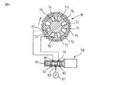
一方、図4は図1において吸気弁7を駆動するためのカムシャフト70の端部に取付けられた可変バルブタイミング機構Bを示している。図4を参照すると、この可変バルブタイミング機構Bは機関のクランク軸によりタイミングベルトを介して矢印方向に回転せしめられるタイミングプーリ71と、タイミングプーリ71と一緒に回転する円筒状ハウジング72と、吸気弁駆動用カムシャフト70と一緒に回転しかつ円筒状ハウジング72に対して相対回転可能な回転軸73と、円筒状ハウジング72の内周面から回転軸73の外周面まで延びる複数個の仕切壁74と、各仕切壁74の間で回転軸73の外周面から円筒状ハウジング72の内周面まで延びるベーン75とを具備しており、各ベーン75の両側には夫々進角用油圧室76と遅角用油圧室77とが形成されている。
On the other hand, FIG. 4 shows the variable valve timing mechanism B attached to the end of the
各油圧室76,77への作動油の供給制御は作動油供給制御弁78によって行われる。この作動油供給制御弁78は各油圧室76,77に夫々連結された油圧ポート79,80と、油圧ポンプ81から吐出された作動油の供給ポート82と、一対のドレインポート83,84と、各ポート79,80,82,83,84間の連通遮断制御を行うスプール弁85とを具備している。
The hydraulic oil supply control to the
吸気弁駆動用カムシャフト70のカムの位相を進角すべきときは図4においてスプール弁85が右方に移動せしめられ、供給ポート82から供給された作動油が油圧ポート79を介して進角用油圧室76に供給されると共に遅角用油圧室77内の作動油がドレインポート84から排出される。このとき回転軸73は円筒状ハウジング72に対して矢印方向に相対回転せしめられる。
When the cam phase of the intake
これに対し、吸気弁駆動用カムシャフト70のカムの位相を遅角すべきときは図4においてスプール弁85が左方に移動せしめられ、供給ポート82から供給された作動油が油圧ポート80を介して遅角用油圧室77に供給されると共に進角用油圧室76内の作動油がドレインポート83から排出される。このとき回転軸73は円筒状ハウジング72に対して矢印と反対方向に相対回転せしめられる。
On the other hand, when the cam phase of the intake
回転軸73が円筒状ハウジング72に対して相対回転せしめられているときにスプール弁85が図4に示される中立位置に戻されると回転軸73の相対回転動作は停止せしめられ、回転軸73はそのときの相対回転位置に保持される。従って可変バルブタイミング機構Bによって吸気弁駆動用カムシャフト70のカムの位相を所望の量だけ進角させることができ、遅角させることができることになる。
If the
図5において実線は可変バルブタイミング機構Bによって吸気弁駆動用カムシャフト70のカムの位相が最も進角されているときを示しており、破線は吸気弁駆動用カムシャフト70のカムの位相が最も遅角されているときを示している。従って吸気弁7の開弁期間は図5において実線で示す範囲と破線で示す範囲との間で任意に設定することができ、従って吸気弁7の閉弁時期も図5において矢印Cで示す範囲内の任意のクランク角に設定することができる。
In FIG. 5, the solid line shows the time when the cam phase of the intake
図1および図4に示される可変バルブタイミング機構Bは一例を示すものであって、例えば吸気弁の開弁時期を一定に維持したまま吸気弁の閉弁時期のみを変えることのできる可変バルブタイミング機構等、種々の形式の可変バルブタイミング機構を用いることができる。 The variable valve timing mechanism B shown in FIG. 1 and FIG. 4 shows an example. For example, the variable valve timing that can change only the closing timing of the intake valve while keeping the opening timing of the intake valve constant. Various types of variable valve timing mechanisms, such as mechanisms, can be used.
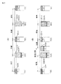
次に図6を参照しつつ本願において使用されている用語の意味について説明する。なお、図6の(A),(B),(C)には説明のために燃焼室容積が50mlでピストンの行程容積が500mlであるエンジンが示されており、これら図6の(A),(B),(C)において燃焼室容積とはピストンが圧縮上死点に位置するときの燃焼室の容積を表している。 Next, the meanings of terms used in the present application will be described with reference to FIG. 6 (A), (B), and (C) show an engine having a combustion chamber volume of 50 ml and a piston stroke volume of 500 ml for the sake of explanation. , (B), (C), the combustion chamber volume represents the volume of the combustion chamber when the piston is located at the compression top dead center.
図6(A)は機械圧縮比について説明している。機械圧縮比は圧縮行程時のピストンの行程容積と燃焼室容積のみから機械的に定まる値であってこの機械圧縮比は(燃焼室容積+行程容積)/燃焼室容積で表される。図6(A)に示される例ではこの機械圧縮比は(50ml+500ml)/50ml=11となる。 FIG. 6A explains the mechanical compression ratio. The mechanical compression ratio is a value mechanically determined only from the stroke volume of the piston and the combustion chamber volume during the compression stroke, and this mechanical compression ratio is expressed by (combustion chamber volume + stroke volume) / combustion chamber volume. In the example shown in FIG. 6A, this mechanical compression ratio is (50 ml + 500 ml) / 50 ml = 11.
図6(B)は実圧縮比について説明している。この実圧縮比は実際に圧縮作用が開始されたときからピストンが上死点に達するまでの実際のピストン行程容積と燃焼室容積から定まる値であってこの実圧縮比は(燃焼室容積+実際の行程容積)/燃焼室容積で表される。即ち、図6(B)に示されるように圧縮行程においてピストンが上昇を開始しても吸気弁が開弁している間は圧縮作用は行われず、吸気弁が閉弁したときから実際の圧縮作用が開始される。従って実圧縮比は実際の行程容積を用いて上記の如く表される。図6(B)に示される例では実圧縮比は(50ml+450ml)/50ml=10となる。 FIG. 6B describes the actual compression ratio. This actual compression ratio is a value determined from the actual piston stroke volume and the combustion chamber volume from when the compression action is actually started until the piston reaches top dead center, and this actual compression ratio is (combustion chamber volume + actual (Stroke volume) / combustion chamber volume. That is, as shown in FIG. 6B, even if the piston starts to rise in the compression stroke, the compression operation is not performed while the intake valve is open, and the actual compression is performed from the time when the intake valve is closed. The action begins. Therefore, the actual compression ratio is expressed as described above using the actual stroke volume. In the example shown in FIG. 6B, the actual compression ratio is (50 ml + 450 ml) / 50 ml = 10.
図6(C)は膨張比について説明している。膨張比は膨張行程時のピストンの行程容積と燃焼室容積から定まる値であってこの膨張比は(燃焼室容積+行程容積)/燃焼室容積で表される。図6(C)に示される例ではこの膨張比は(50ml+500ml)/50ml=11となる。 FIG. 6C illustrates the expansion ratio. The expansion ratio is a value determined from the stroke volume of the piston and the combustion chamber volume during the expansion stroke, and this expansion ratio is expressed by (combustion chamber volume + stroke volume) / combustion chamber volume. In the example shown in FIG. 6C, this expansion ratio is (50 ml + 500 ml) / 50 ml = 11.
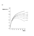
次に図7および図8を参照しつつ本発明において用いられている超膨張比サイクルについて説明する。なお、図7は理論熱効率と膨張比との関係を示しており、図8は本発明において負荷に応じ使い分けられている通常のサイクルと超高膨張比サイクルとの比較を示している。 Next, the super expansion ratio cycle used in the present invention will be described with reference to FIGS. FIG. 7 shows the relationship between the theoretical thermal efficiency and the expansion ratio, and FIG. 8 shows a comparison between a normal cycle and an ultrahigh expansion ratio cycle that are selectively used according to the load in the present invention.
図8(A)は吸気弁が下死点近傍で閉弁し、ほぼ吸気下死点付近からピストンによる圧縮作用が開始される場合の通常のサイクルを示している。この図8(A)に示す例でも図6の(A),(B),(C)に示す例と同様に燃焼室容積が50mlとされ、ピストンの行程容積が500mlとされている。図8(A)からわかるように通常のサイクルでは機械圧縮比は(50ml+500ml)/50ml=11であり、実圧縮比もほぼ11であり、膨張比も(50ml+500ml)/50ml=11となる。即ち、通常の内燃機関では機械圧縮比と実圧縮比と膨張比とがほぼ等しくなる。 FIG. 8A shows a normal cycle when the intake valve closes near the bottom dead center and the compression action by the piston is started from the vicinity of the intake bottom dead center. In the example shown in FIG. 8A as well, the combustion chamber volume is set to 50 ml, and the stroke volume of the piston is set to 500 ml, similarly to the example shown in FIGS. 6A, 6B, and 6C. As can be seen from FIG. 8A, in a normal cycle, the mechanical compression ratio is (50 ml + 500 ml) / 50 ml = 11, the actual compression ratio is almost 11, and the expansion ratio is also (50 ml + 500 ml) / 50 ml = 11. That is, in a normal internal combustion engine, the mechanical compression ratio, the actual compression ratio, and the expansion ratio are substantially equal.
図7における実線は実圧縮比と膨張比とがほぼ等しい場合の、即ち通常のサイクルにおける理論熱効率の変化を示している。この場合には膨張比が大きくなるほど、即ち実圧縮比が高くなるほど理論熱効率が高くなることがわかる。従って通常のサイクルにおいて理論熱効率を高めるには実圧縮比を高くすればよいことになる。しかしながら機関高負荷運転時におけるノッキングの発生の制約により実圧縮比は最大でも12程度までしか高くすることができず、斯くして通常のサイクルにおいては理論熱効率を十分に高くすることはできない。 The solid line in FIG. 7 shows the change in the theoretical thermal efficiency when the actual compression ratio and the expansion ratio are substantially equal, that is, in a normal cycle. In this case, it can be seen that the theoretical thermal efficiency increases as the expansion ratio increases, that is, as the actual compression ratio increases. Therefore, in order to increase the theoretical thermal efficiency in a normal cycle, it is only necessary to increase the actual compression ratio. However, the actual compression ratio can only be increased to a maximum of about 12 due to the restriction of the occurrence of knocking at the time of engine high load operation, and thus the theoretical thermal efficiency cannot be sufficiently increased in a normal cycle.
一方、このような状況下で機械圧縮比と実圧縮比とを厳密に区分しつつ理論熱効率を高めることが検討され、その結果理論熱効率は膨張比が支配し、理論熱効率に対して実圧縮比はほとんど影響を与えないことが見い出されたのである。即ち、実圧縮比を高くすると爆発力は高まるが圧縮するために大きなエネルギーが必要となり、斯くして実圧縮比を高めても理論熱効率はほとんど高くならない。 On the other hand, under such circumstances, it is considered to increase the theoretical thermal efficiency while strictly dividing the mechanical compression ratio and the actual compression ratio. As a result, the theoretical thermal efficiency is governed by the expansion ratio, and the actual compression ratio is compared to the theoretical thermal efficiency. Was found to have little effect. That is, if the actual compression ratio is increased, the explosive force is increased, but a large amount of energy is required for compression. Thus, even if the actual compression ratio is increased, the theoretical thermal efficiency is hardly increased.
これに対し、膨張比を大きくすると膨張行程時にピストンに対し押下げ力が作用する期間が長くなり、斯くしてピストンがクランクシャフトに回転力を与えている期間が長くなる。従って膨張比は大きくすれば大きくするほど理論熱効率が高くなる。図7の破線ε=10は実圧縮比を10に固定した状態で膨張比を高くしていった場合の理論熱効率を示している。このように実圧縮比εを低い値に維持した状態で膨張比を高くしたときの理論熱効率の上昇量と、図7の実線で示す如く実圧縮比も膨張比と共に増大せしめられる場合の理論熱効率の上昇量とは大きな差がないことがわかる。 On the other hand, when the expansion ratio is increased, the period during which the pressing force acts on the piston during the expansion stroke becomes longer, and thus the period during which the piston applies the rotational force to the crankshaft becomes longer. Therefore, the larger the expansion ratio, the higher the theoretical thermal efficiency. The broken line ε = 10 in FIG. 7 indicates the theoretical thermal efficiency when the expansion ratio is increased with the actual compression ratio fixed at 10. Thus, the theoretical thermal efficiency when the expansion ratio is increased while the actual compression ratio ε is maintained at a low value, and the theoretical thermal efficiency when the actual compression ratio is increased with the expansion ratio as shown by the solid line in FIG. It can be seen that there is no significant difference from the amount of increase.
このように実圧縮比が低い値に維持されているとノッキングが発生することがなく、従って実圧縮比を低い値に維持した状態で膨張比を高くするとノッキングの発生を阻止しつつ理論熱効率を大巾に高めることができる。図8(B)は可変圧縮比機構Aおよび可変バルブタイミング機構Bを用いて、実圧縮比を低い値に維持しつつ膨張比を高めるようにした場合の一例を示している。 Thus, if the actual compression ratio is maintained at a low value, knocking does not occur. Therefore, if the expansion ratio is increased while the actual compression ratio is maintained at a low value, the theoretical thermal efficiency is reduced while preventing the occurrence of knocking. Can be greatly increased. FIG. 8B shows an example where the variable compression ratio mechanism A and variable valve timing mechanism B are used to increase the expansion ratio while maintaining the actual compression ratio at a low value.
図8(B)を参照すると、この例では可変圧縮比機構Aにより燃焼室容積が50mlから20mlまで減少せしめられる。一方、可変バルブタイミング機構Bによって実際のピストン行程容積が500mlから200mlになるまで吸気弁の閉弁時期が遅らされる。その結果、この例では実圧縮比は(20ml+200ml)/20ml=11となり、膨張比は(20ml+500ml)/20ml=26となる。図8(A)に示される通常のサイクルでは前述したように実圧縮比がほぼ11で膨張比が11であり、この場合に比べると図8(B)に示される場合には膨張比のみが26まで高められていることがわかる。これが超高膨張比サイクルと称される所以である。 Referring to FIG. 8B, in this example, the variable compression ratio mechanism A reduces the combustion chamber volume from 50 ml to 20 ml. On the other hand, the variable valve timing mechanism B delays the closing timing of the intake valve until the actual piston stroke volume is reduced from 500 ml to 200 ml. As a result, in this example, the actual compression ratio is (20 ml + 200 ml) / 20 ml = 11, and the expansion ratio is (20 ml + 500 ml) / 20 ml = 26. In the normal cycle shown in FIG. 8A, the actual compression ratio is almost 11 and the expansion ratio is 11, as described above. Compared with this case, only the expansion ratio is shown in FIG. 8B. It can be seen that it has been increased to 26. This is why it is called an ultra-high expansion ratio cycle.
一般的に言って内燃機関では機関負荷が低いほど熱効率が悪くなり、従って機関運転時における熱効率を向上させるためには、即ち燃費を向上させるには機関負荷が低いときの熱効率を向上させることが必要となる。一方、図8(B)に示される超高膨張比サイクルでは圧縮行程時の実際のピストン行程容積が小さくされるために燃焼室5内に吸入しうる吸入空気量は少なくなり、従ってこの超高膨張比サイクルは機関負荷が比較的低いときにしか採用できないことになる。従って本発明では機関負荷が比較的低いときには図8(B)に示す超高膨張比サイクルとし、機関高負荷運転時には図8(A)に示す通常のサイクルとするようにしている。
Generally speaking, in an internal combustion engine, the lower the engine load, the worse the thermal efficiency. Therefore, in order to improve the thermal efficiency during engine operation, that is, to improve fuel efficiency, it is necessary to improve the thermal efficiency when the engine load is low. Necessary. On the other hand, in the ultra-high expansion ratio cycle shown in FIG. 8B, since the actual piston stroke volume during the compression stroke is reduced, the amount of intake air that can be sucked into the
次に図9を参照しつつ運転制御全般について概略的に説明する。図9には或る機関回転数における機関負荷に応じた吸入空気量、吸気弁閉弁時期、機械圧縮比、膨張比、実圧縮比およびスロットル弁17の開度の各変化が示されている。なお、図9は、触媒装置20内の三元触媒によって排気ガス中の未燃HC,COおよびNOXを同時に低減しうるように燃焼室5内における平均空燃比が空燃比センサ21の出力信号に基いて理論空燃比にフィードバック制御されている場合を示している。
Next, the overall operation control will be schematically described with reference to FIG. FIG. 9 shows changes in the intake air amount, the intake valve closing timing, the mechanical compression ratio, the expansion ratio, the actual compression ratio, and the opening degree of the throttle valve 17 according to the engine load at a certain engine speed. . 9 shows that the average air-fuel ratio in the
さて、前述したように機関高負荷運転時には図8(A)に示される通常のサイクルが実行される。従って図9に示されるようにこのときには機械圧縮比は低くされるために膨張比は低く、図9において実線で示されるように吸気弁7の閉弁時期は図5において実線で示される如く早められている。また、このときには吸入空気量は多く、このときスロットル弁17の開度は全開に保持されているのでポンピング損失は零となっている。
As described above, the normal cycle shown in FIG. 8 (A) is executed during engine high load operation. Accordingly, as shown in FIG. 9, the expansion ratio is low because the mechanical compression ratio is lowered at this time, and the valve closing timing of the
一方、図9において実線で示されるように機関負荷が低くなるとそれに伴って吸入空気量を減少すべく吸気弁7の閉弁時期が遅くされる。またこのときには実圧縮比がほぼ一定に保持されるように図9に示される如く機関負荷が低くなるにつれて機械圧縮比が増大され、従って機関負荷が低くなるにつれて膨張比も増大される。なお、このときにもスロットル弁17は全開状態に保持されており、従って燃焼室5内に供給される吸入空気量はスロットル弁17によらずに吸気弁7の閉弁時期を変えることによって制御されている。
On the other hand, as shown by the solid line in FIG. 9, when the engine load becomes low, the closing timing of the
このように機関高負荷運転状態から機関負荷が低くなるときには実圧縮比がほぼ一定のもとで吸入空気量が減少するにつれて機械圧縮比が増大せしめられる。即ち、吸入空気量の減少に比例してピストン4が圧縮上死点に達したときの燃焼室5の容積が減少せしめられる。従ってピストン4が圧縮上死点に達したときの燃焼室5の容積は吸入空気量に比例して変化していることになる。なお、このとき図9に示される例では燃焼室5内の空燃比は理論空燃比となっているのでピストン4が圧縮上死点に達したときの燃焼室5の容積は燃料量に比例して変化していることになる。
As described above, when the engine load is reduced from the engine high load operation state, the mechanical compression ratio is increased as the intake air amount is decreased while the actual compression ratio is substantially constant. That is, the volume of the
機関負荷が更に低くなると機械圧縮比は更に増大せしめられ、機関負荷がやや低負荷寄りの中負荷L1まで低下すると機械圧縮比は燃焼室5の構造上限界となる限界機械圧縮比(上限機械圧縮比)に達する。機械圧縮比が限界機械圧縮比に達すると、機械圧縮比が限界機械圧縮比に達したときの機関負荷L1よりも負荷の低い領域では機械圧縮比が限界機械圧縮比に保持される。従って低負荷側の機関中負荷運転時および機関低負荷運転時には即ち、機関低負荷運転側では機械圧縮比は最大となり、膨張比も最大となる。別の言い方をすると機関低負荷運転側では最大の膨張比が得られるように機械圧縮比が最大にされる。
When the engine load is further reduced, the mechanical compression ratio is further increased, and when the engine load is lowered to the medium load L1 slightly close to the low load, the mechanical compression ratio becomes a limit mechanical compression ratio (upper limit mechanical compression) that becomes the structural limit of the
一方、図9に示される実施例では機関負荷がL1まで低下すると吸気弁7の閉弁時期が燃焼室5内に供給される吸入空気量を制御しうる限界閉弁時期となる。吸気弁7の閉弁時期が限界閉弁時期に達すると吸気弁7の閉弁時期が限界閉弁時期に達したときの機関負荷L1よりも負荷の低い領域では吸気弁7の閉弁時期が限界閉弁時期に保持される。
On the other hand, in the embodiment shown in FIG. 9, when the engine load decreases to L1, the closing timing of the
吸気弁7の閉弁時期が限界閉弁時期に保持されるともはや吸気弁7の閉弁時期の変化によっては吸入空気量を制御することができない。図9に示される実施例ではこのとき、即ち吸気弁7の閉弁時期が限界閉弁時期に達したときの機関負荷L1よりも負荷の低い領域ではスロットル弁17によって燃焼室5内に供給される吸入空気量が制御され、機関負荷が低くなるほどスロットル弁17の開度は小さくされる。本実施例において、吸入空気量は吸気弁7の閉弁時期を図9において実線で示すように変化させても制御するようになっている。
When the closing timing of the
前述したように図8(B)に示す超高膨張比サイクルでは膨張比が26とされる。この膨張比は高いほど好ましいが図7からわかるように実用上使用可能な下限実圧縮比ε=5に対しても20以上であればかなり高い理論熱効率を得ることができる。従って本実施例では膨張比が20以上となるように可変圧縮比機構Aが形成されている。 As described above, the expansion ratio is 26 in the ultra-high expansion ratio cycle shown in FIG. The higher the expansion ratio, the better. However, as can be seen from FIG. 7, a considerably high theoretical thermal efficiency can be obtained if it is 20 or more with respect to the practically usable lower limit actual compression ratio ε = 5. Therefore, in this embodiment, the variable compression ratio mechanism A is formed so that the expansion ratio is 20 or more.
ところで、内燃機関においては、ノッキングの発生を抑制しなければならず、そのために、本実施例の内燃機関では、電子制御ユニット30により図10に示すフローチャートの制御が実施される。先ず、ステップ101において、前述したように、現在の機関負荷に基づき可変バルブタイミング機構Bにより制御する吸気弁の閉弁時期IVCが設定される。ステップ102では、設定された吸気弁の閉弁時期IVCが点火時期の設定時期ITTより前であるか否かが判断される。ここで、点火時期の設定時期ITTは、実際の点火時期までに点火栓6のコイルへの予め定められた通電時間等が必要となるために、圧縮行程中期の予め定められたクランク角度とされる。
By the way, in the internal combustion engine, it is necessary to suppress the occurrence of knocking. For this reason, in the internal combustion engine of the present embodiment, the
ステップ102の判断が肯定されるときには、点火時期の設定時期ITTより前に吸気弁が閉弁されることとなり、ステップ103において、吸気弁の閉弁時期において、各気筒に配置された筒内圧力センサ(図示せず)により吸気弁が閉弁された気筒(対応気筒)内の吸気圧力Pmが測定される(又は、サージタンク12に配置された圧力センサ(図示せず)の吸気弁閉弁時の測定値を対応気筒の吸気弁閉弁時の吸気圧力Pmとしても良い)。次いで、ステップ104において、次式により対応気筒の圧縮端圧力Peが推定される。
Pe=Pm(Vm/Ve)k
ここで、Vmは吸気弁閉弁時の燃焼室容積(圧縮上死点の燃焼室容積+実際の行程容積)であり、Veは圧縮上死点の燃焼室容積であり、kは比熱比である。(Vm/Ve)は前述した実圧縮比となる。圧縮上死点の燃焼室容積は、相対位置センサ22の出力に基づき正確に推定することができ、実際の行程容積は、実際の吸気弁閉弁時期に基づき正確に推定することができ、こうして、吸気弁の閉弁時期又はそれ以降において、対応気筒の圧縮端圧力Peを正確に推定することができる。
If the determination in
Pe = Pm (Vm / Ve) k
Here, Vm is the combustion chamber volume when the intake valve is closed (combustion chamber volume at compression top dead center + actual stroke volume), Ve is the combustion chamber volume at compression top dead center, and k is the specific heat ratio. is there. (Vm / Ve) is the actual compression ratio described above. The combustion chamber volume at the compression top dead center can be accurately estimated based on the output of the
次いで、ステップ105では、点火時期の設定時期ITTとなると、ステップ104において推定された対応気筒の圧縮端圧力Peに対してノッキングを発生させないで最も高いトルクを発生する点火時期ITを設定する。こうして設定された点火時期ITにおいて点火が実施されれば、対応気筒においてノッキングの発生を十分に抑制することができる。
Next, at
一方、吸気弁の閉弁時期IVCが点火時期の設定時期ITT以降である場合には、ステップ102の判断が否定され、ステップ106において、点火時期の設定時期ITTにおいて、点火時期ITとして、現在の機関運転状態(機関負荷、機関回転数、目標機械圧縮比、及び、吸気弁の閉弁時期IVCなど)に対して予め定められている最適点火時期(MBT)を設定する。ここで、前述のステップ105においては、ステップ104において推定された圧縮端圧力Peが現在の機関運転状態において想定されている圧縮端圧力より高い場合に、現在の機関運転状態の最適点火時期(MBT)を遅角側に補正するようにしても良い。
On the other hand, if the intake valve closing timing IVC is after the ignition timing setting timing ITT, the determination in
ステップ107では、吸気弁の閉弁時期IVCとなると、ステップ103と同様に対応気筒の吸気弁閉弁時の吸気圧力Pmが測定され、次いで、ステップ104と同様に対応気筒の圧縮端圧力Peが推定される。次いで、ステップ109では、吸気弁の閉弁時期又はそれ以降において推定される正確な圧縮端圧力Peに対して設定時期ITTにおいて設定された最適点火時期ではノッキングが発生するが否かが予測される。例えば、吸気弁閉弁時の吸気圧力Pmが現在の機関運転状態において想定されている圧力より高いとき、圧縮上死点の燃焼室容積が現在の機関運転状態において想定されている容積より小さいとき、又は、吸気弁の閉弁時期が現在の機関運転状態において想定されている時期より進角側であるときなどにおいて、推定圧縮端圧力Peが現在の機関運転状態において想定されている圧力より高くなる。推定圧縮端圧力Peが現在の機関運転状態において想定されている圧縮端圧力より設定値以上高くなる場合には、現在の機関運転状態に対して設定されている最適点火時期ではノッキングが発生すると予測することができる。
In
ステップ109の判断が否定されるときにはそのまま終了するが、ノッキングが発生すると予測されるときには、ステップ110において、直ちに可変圧縮比機構Aを作動させて機械圧縮比を低下させる。それにより、対応気筒において、推定圧縮端圧力を低下させることができ、ノッキングの発生を抑制することができる。ここで、ステップ106において設定された点火時期ITまでに、推定圧縮端圧力を現在の機関運転状態において想定されている圧縮端圧力とするまで機械圧縮比を低下させることが好ましいが、点火時期ITまでに僅かでも機械圧縮比を低下させることができれば、推定圧縮端圧力を低下させることができ、ノッキングの発生を抑制することができる。
If the determination in
また、点火時期ITまでに、推定圧縮端圧力を現在の機関運転状態において想定されている圧縮端圧力とするまで機械圧縮比を低下させることができない場合には、点火時期IT以降にも機械圧縮比を低下させ続けることが好ましい。それにより、燃焼開始以降にも筒内圧力を低下させて、ノッキングの発生を抑制することができる。また、燃焼中であれば圧縮上死点以降においても機械圧縮比を低下させることにより筒内圧力を低下させることが好ましく、それにより、ノッキングの発生を抑制することができ、また、ノッキングが発生してもノッキングの持続を抑制することができる。 Further, when the mechanical compression ratio cannot be reduced until the estimated compression end pressure becomes the compression end pressure assumed in the current engine operating state by the ignition timing IT, the mechanical compression is also performed after the ignition timing IT. It is preferable to keep the ratio down. Thereby, the in-cylinder pressure can be reduced even after the start of combustion, and the occurrence of knocking can be suppressed. Further, if it is during combustion, it is preferable to reduce the in-cylinder pressure by reducing the mechanical compression ratio even after compression top dead center, so that the occurrence of knocking can be suppressed and the occurrence of knocking Even so, the duration of knocking can be suppressed.
このように、ノッキングが発生すると予測されるときには、機械圧縮比の低下を可能な限り早期に開始することが好ましいが、点火時期以降であっても、燃焼中であれば圧縮上死点以降であっても、機械圧縮比の低下を開始すれば、ノッキングを抑制することができる。 Thus, when it is predicted that knocking will occur, it is preferable to start the reduction of the mechanical compression ratio as early as possible, but even after the ignition timing, if it is in combustion, it will be after the compression top dead center. Even if it starts, knocking can be suppressed if the reduction of the mechanical compression ratio is started.
次に吸気弁が閉弁される気筒においては、機械圧縮比が十分に低下されれば、圧縮上死点の燃焼室容積が大きくなっており、吸気弁閉弁時に推定される圧縮端圧力は現在の機関運転状態において想定される圧縮端圧力まで低くなって、ステップ109においてノッキングの発生が予測されなくなる。
Next, in the cylinder where the intake valve is closed, if the mechanical compression ratio is sufficiently lowered, the combustion chamber volume at the compression top dead center is increased, and the compression end pressure estimated when the intake valve is closed is In
また、燃料噴射弁13が気筒内へ直接的に燃料を噴射するものであれば、ステップ109の判断が肯定されるときには、さらに、ステップ111のように、直ちに燃料噴射弁13により追加燃料を対応気筒内へ供給するようにしても良い。それにより、このような追加燃料の気化潜熱によって点火時期での筒内温度を低下させることができ、さらにノッキングの発生を抑制することができる。
Further, if the
ノッキングが発生すると予測されるときの追加燃料の供給は、可能な限り早期に開始することが好ましいが、点火時期以降であっても、燃焼中であれば圧縮上死点以降であっても、筒内温度を低下させてノッキングを抑制することができ、また、ノッキングが発生してもノッキングの持続を抑制することができる。 The supply of additional fuel when knocking is predicted to occur is preferably started as early as possible, but even after the ignition timing, or even after compression top dead center during combustion, The in-cylinder temperature can be reduced to suppress knocking, and even if knocking occurs, the duration of knocking can be suppressed.
本実施例において、吸気弁の閉弁時期IVCが点火時期の設定時期ITTより前であるときにも、吸気弁の閉弁時期以降に推定される正確な圧縮端圧力Peに対して現在の機関運転状態の最適点火時期ではノッキングが発生すると予測される場合にステップ110のように可変圧縮比機構Aにより機械圧縮比を低下させてノッキングの発生を抑制することも可能であるが、点火時期制御に比較して可変圧縮比機構Aを作動させると、多量の電気エネルギーを消費することとなるために、このときには、ステップ105の点火時期制御によりノッキングの発生を抑制する方が好ましい。
In this embodiment, even when the intake valve closing timing IVC is earlier than the ignition timing setting timing ITT, the current engine is used for the accurate compression end pressure Pe estimated after the intake valve closing timing. When knocking is predicted to occur at the optimum ignition timing in the operating state, it is possible to reduce the mechanical compression ratio by the variable compression ratio mechanism A and suppress the occurrence of knocking as in
1 クランクケース
2 シリンダブロック
6 点火栓
13 燃料噴射弁
A 可変圧縮比機構
B 可変バルブタイミング機構
DESCRIPTION OF SYMBOLS 1 Crankcase 2
Claims (2)
Priority Applications (1)
| Application Number | Priority Date | Filing Date | Title |
|---|---|---|---|
| JP2011063852A JP2012197770A (en) | 2011-03-23 | 2011-03-23 | Internal combustion engine with variable compression ratio mechanism |
Applications Claiming Priority (1)
| Application Number | Priority Date | Filing Date | Title |
|---|---|---|---|
| JP2011063852A JP2012197770A (en) | 2011-03-23 | 2011-03-23 | Internal combustion engine with variable compression ratio mechanism |
Publications (1)
| Publication Number | Publication Date |
|---|---|
| JP2012197770A true JP2012197770A (en) | 2012-10-18 |
Family
ID=47180235
Family Applications (1)
| Application Number | Title | Priority Date | Filing Date |
|---|---|---|---|
| JP2011063852A Withdrawn JP2012197770A (en) | 2011-03-23 | 2011-03-23 | Internal combustion engine with variable compression ratio mechanism |
Country Status (1)
| Country | Link |
|---|---|
| JP (1) | JP2012197770A (en) |
Cited By (3)
| Publication number | Priority date | Publication date | Assignee | Title |
|---|---|---|---|---|
| US9617925B2 (en) | 2015-07-07 | 2017-04-11 | Hyundai Motor Company | Control method using continuous variable valve duration apparatus |
| JP2017125435A (en) * | 2016-01-13 | 2017-07-20 | トヨタ自動車株式会社 | Control device for internal combustion engine |
| US9803519B2 (en) | 2014-12-10 | 2017-10-31 | Hyundai Motor Company | Continuous variable valve duration apparatus and control method using the same |
-
2011
- 2011-03-23 JP JP2011063852A patent/JP2012197770A/en not_active Withdrawn
Cited By (3)
| Publication number | Priority date | Publication date | Assignee | Title |
|---|---|---|---|---|
| US9803519B2 (en) | 2014-12-10 | 2017-10-31 | Hyundai Motor Company | Continuous variable valve duration apparatus and control method using the same |
| US9617925B2 (en) | 2015-07-07 | 2017-04-11 | Hyundai Motor Company | Control method using continuous variable valve duration apparatus |
| JP2017125435A (en) * | 2016-01-13 | 2017-07-20 | トヨタ自動車株式会社 | Control device for internal combustion engine |
Similar Documents
| Publication | Publication Date | Title |
|---|---|---|
| JP2007303423A (en) | Spark ignition internal combustion engine | |
| JP4450025B2 (en) | Spark ignition internal combustion engine | |
| JPWO2011080844A1 (en) | Spark ignition internal combustion engine | |
| JP4367549B2 (en) | Spark ignition internal combustion engine | |
| JP4849188B2 (en) | Spark ignition internal combustion engine | |
| JP5472076B2 (en) | Spark ignition internal combustion engine | |
| JP4367548B2 (en) | Spark ignition internal combustion engine | |
| JP4450026B2 (en) | Spark ignition internal combustion engine | |
| JP4367551B2 (en) | Spark ignition internal combustion engine | |
| JP4725561B2 (en) | Spark ignition internal combustion engine | |
| JP5472195B2 (en) | Internal combustion engine having a variable compression ratio mechanism | |
| JP2012197770A (en) | Internal combustion engine with variable compression ratio mechanism | |
| JP5088448B1 (en) | Spark ignition internal combustion engine | |
| JP4367547B2 (en) | Spark ignition internal combustion engine | |
| JP2009215913A (en) | Spark ignition type internal combustion engine | |
| JP5428928B2 (en) | Spark ignition internal combustion engine | |
| JP4911144B2 (en) | Spark ignition internal combustion engine | |
| JP5640753B2 (en) | Spark ignition internal combustion engine | |
| JP5321422B2 (en) | Spark ignition internal combustion engine | |
| JP5516461B2 (en) | Internal combustion engine having a variable compression ratio mechanism | |
| JP5640512B2 (en) | Spark ignition internal combustion engine | |
| JP4420105B2 (en) | Spark ignition internal combustion engine | |
| JP5429136B2 (en) | Spark ignition internal combustion engine | |
| JP5754369B2 (en) | Internal combustion engine having a variable compression ratio mechanism | |
| JP5472136B2 (en) | Spark ignition internal combustion engine |
Legal Events
| Date | Code | Title | Description |
|---|---|---|---|
| A300 | Application deemed to be withdrawn because no request for examination was validly filed |
Free format text: JAPANESE INTERMEDIATE CODE: A300 Effective date: 20140603 |