JP2012197801A - Rolling bearing unit with combination seal ring, and method for manufacturing the same - Google Patents

Rolling bearing unit with combination seal ring, and method for manufacturing the same Download PDF

Info

Publication number
JP2012197801A
JP2012197801A JP2010231427A JP2010231427A JP2012197801A JP 2012197801 A JP2012197801 A JP 2012197801A JP 2010231427 A JP2010231427 A JP 2010231427A JP 2010231427 A JP2010231427 A JP 2010231427A JP 2012197801 A JP2012197801 A JP 2012197801A
Authority
JP
Japan
Prior art keywords
slinger
ring
fitting
seal ring
cylindrical portion
Prior art date
Legal status (The legal status is an assumption and is not a legal conclusion. Google has not performed a legal analysis and makes no representation as to the accuracy of the status listed.)
Pending
Application number
JP2010231427A
Other languages
Japanese (ja)
Inventor
Hirofumi Kurohara
博文 黒原
Current Assignee (The listed assignees may be inaccurate. Google has not performed a legal analysis and makes no representation or warranty as to the accuracy of the list.)
NSK Ltd
Original Assignee
NSK Ltd
Priority date (The priority date is an assumption and is not a legal conclusion. Google has not performed a legal analysis and makes no representation as to the accuracy of the date listed.)
Filing date
Publication date
Application filed by NSK Ltd filed Critical NSK Ltd
Priority to JP2010231427A priority Critical patent/JP2012197801A/en
Priority to EP11732852.6A priority patent/EP2525110B1/en
Priority to US13/522,058 priority patent/US8708571B2/en
Priority to PCT/JP2011/050236 priority patent/WO2011086982A1/en
Priority to CN201180000021.8A priority patent/CN102239341B/en
Priority to JP2011549967A priority patent/JP5565418B2/en
Publication of JP2012197801A publication Critical patent/JP2012197801A/en
Pending legal-status Critical Current

Links

Images

Landscapes

  • Rolling Contact Bearings (AREA)

Abstract

【課題】グリースが外部空間に漏洩し易くなると共に、外部空間に存在する水分や塵芥等の異物が環状空間内に侵入し易くなる傷が付かない様に、一方の軌道輪とスリンガとの嵌合部のシール性が損なわれることなく組み立てられる構造を実現する。
【解決手段】内輪19aの表面のスリンガ用嵌合面20部分と、面取り部25a部分と、両部分同士の繋ぎ目27a部分とから成る互いに連続した部分を、内輪19aの熱処理後に、総型の回転砥石により同時に研削することにより、互いに連続した部分全体を、断面形状に関して微分不能な角部がない平滑面として、円筒部15の内周面に傷が付かない様に、スリンガ用嵌合面20に円筒部15を圧入する。
【選択図】図1
[PROBLEMS] To prevent grease from leaking to an external space and to prevent a foreign matter such as moisture or dust existing in the external space from entering the annular space from being scratched, A structure that can be assembled without impairing the sealing performance of the joint is realized.
A continuous portion consisting of a fitting surface portion for slinger on the surface of an inner ring, a chamfered portion, and a joint portion between both portions is subjected to a heat treatment of the inner ring after a heat treatment of the inner ring. By simultaneously grinding with a rotating grindstone, the entire continuous portion is made a smooth surface without a corner portion that cannot be differentiated with respect to the cross-sectional shape, so that the inner peripheral surface of the cylindrical portion 15 is not scratched. The cylindrical portion 15 is press-fitted into 20.
[Selection] Figure 1

Description

この発明は、例えば自動車の車輪を懸架装置に対して回転自在に支持する為の転がり軸受ユニットのうち、回転側軌道輪と静止側軌道輪との互いに対向する周面同士の間に存在して複数個の転動体を設置した環状空間の端部開口を、スリンガとシールリングとから成る組み合わせシールリングにより塞いで成る、組み合わせシールリング付転がり軸受ユニット、及び、その製造方法の改良に関する。具体的には、一方の軌道輪と前記スリンガとの嵌合部のシール性が損なわれない様に組み立てられる構造及びその製造方法の実現を図るものである。   The present invention exists, for example, in a rolling bearing unit for rotatably supporting a wheel of an automobile with respect to a suspension device, between circumferential surfaces facing each other of a rotation side raceway and a stationary side raceway. The present invention relates to a rolling bearing unit with a combined seal ring, in which an end opening of an annular space provided with a plurality of rolling elements is closed with a combined seal ring composed of a slinger and a seal ring, and an improvement of the manufacturing method thereof. Specifically, it is intended to realize a structure assembled and a manufacturing method thereof so that the sealing performance of the fitting portion between one of the race rings and the slinger is not impaired.

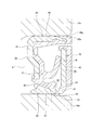
図15〜16は、自動車の車輪を懸架装置に対して回転自在に支持する為の転がり軸受ユニットの従来構造の1例を示している。この図15〜16に示した転がり軸受ユニット1は、使用時に懸架装置に支持固定されて回転しない静止側軌道輪である外輪2と、使用時に車輪を支持固定した状態で回転する回転側軌道輪であるハブ3とを、互いに同心に配置している。そして、この外輪2の内周面に設けた、それぞれが静止側軌道である複列の外輪軌道4、4と、前記ハブ3の外周面に設けた、それぞれが回転側軌道である複列の内輪軌道5、5との間に、それぞれが転動体である玉6、6を、両列毎に複数個ずつ配置している。これら各玉6、6は、それぞれ保持器7、7により、転動自在に保持している。尚、前記ハブ3は、ハブ本体18と、このハブ本体18の軸方向内端部(軸方向に関して「外」とは、自動車への組み付け状態で車両の幅方向外側を言い、各図の左側。反対に、車両の幅方向中央側となる、各図の右側を、軸方向に関して「内」と言う。本明細書全体で同じ。)に外嵌固定した内輪19とから成る。そして、前記両内輪軌道5、5のうち、軸方向外側の内輪軌道5は、前記ハブ本体18の軸方向中間部外周面に、軸方向内側の内輪軌道5は、前記内輪19の外周面に、それぞれ形成されている。   FIGS. 15-16 has shown an example of the conventional structure of the rolling bearing unit for supporting the wheel of a motor vehicle rotatably with respect to a suspension apparatus. The rolling bearing unit 1 shown in FIGS. 15 to 16 includes an outer ring 2 that is a stationary-side bearing ring that is supported and fixed to a suspension device and does not rotate when used, and a rotating-side bearing ring that rotates while supporting and fixing the wheel when used. Are arranged concentrically with each other. And the double row outer ring raceways 4 and 4 each provided on the inner peripheral surface of the outer ring 2 are stationary side raceways, and the double row each provided on the outer peripheral surface of the hub 3 and each is a rotary side raceway. Between the inner ring raceways 5 and 5, a plurality of balls 6 and 6 each of which is a rolling element are arranged in each row. These balls 6 and 6 are held by the cages 7 and 7 so as to be freely rollable. The hub 3 includes a hub main body 18 and an inner end of the hub main body 18 in the axial direction ("outer" with respect to the axial direction refers to the outer side in the width direction of the vehicle when assembled to the automobile, and is the left side of each figure. On the other hand, the right side of each figure, which is the center side in the width direction of the vehicle, is referred to as “inner” in the axial direction, which is the same throughout the present specification. Of the inner ring raceways 5, 5, the inner ring raceway 5 on the outer side in the axial direction is on the outer peripheral surface of the intermediate portion of the hub body 18, and the inner ring raceway 5 on the inner side in the axial direction is on the outer peripheral surface of the inner ring 19. , Each is formed.

前記外輪2の内周面と前記ハブ3の外周面との間で前記各玉6、6を設置した環状空間8の両端開口は、それぞれシールリング9と組み合わせシールリング10とによって、全周に亙り塞いでいる。これにより、前記環状空間8内に存在するグリースが外部空間に漏洩する事の防止と、外部空間に存在する水分や塵芥等の異物が前記環状空間8内に侵入する事の防止とを図っている。前記シールリング9は、弾性材製で円環状のシール部材11と、このシール部材11を補強する円環状の芯金12とを備える。そして、このうちの芯金12を前記外輪2の軸方向外端部に締り嵌めで内嵌した状態で、前記シール部材11を構成する複数本のシールリップの先端縁を前記ハブ本体18の軸方向中間部外周面に、全周に亙り摺接させている。   Openings at both ends of the annular space 8 in which the balls 6, 6 are installed between the inner peripheral surface of the outer ring 2 and the outer peripheral surface of the hub 3 are formed around the entire periphery by a seal ring 9 and a combination seal ring 10, respectively. It is crawling up. Thereby, the grease existing in the annular space 8 is prevented from leaking into the external space, and foreign substances such as moisture and dust existing in the external space are prevented from entering the annular space 8. Yes. The seal ring 9 includes an annular seal member 11 made of an elastic material and an annular cored bar 12 that reinforces the seal member 11. Then, in a state where the core metal 12 is fitted into the outer end of the outer ring 2 in the axial direction, the leading edges of the plurality of seal lips constituting the seal member 11 are connected to the shaft of the hub body 18. It is slidably contacted with the outer peripheral surface of the direction intermediate portion over the entire periphery.

又、前記組み合わせシールリング10は、スリンガ13とシールリング14とから成る。このうちのスリンガ13は、金属板をバーリング加工などのプレス成形にて打ち抜きや曲げ加工する事により断面L字形で全体を円環状に構成したもので、円筒部15と、この円筒部15の軸方向内端縁から径方向外方に折れ曲がった円輪部16と、これら円筒部15と円輪部16との連続部に存在する、断面円弧形の湾曲部17とから成る。この様なスリンガ13は、前記円筒部15を、前記内輪19の軸方向内端部外周面に設けた円筒状のスリンガ用嵌合面20に締り嵌めで外嵌(圧入外嵌)する事により、前記内輪19に対し固定している。又、前記シールリング10は、弾性材製で円環状のシール部材21と、このシール部材21を補強する円環状の芯金22とを備える。この様なシールリング10は、この芯金22の外周縁部に設けた円筒部23を、前記外輪2の軸方向内端部内周面に設けた円筒状のシールリング用嵌合面24に締り嵌めで内嵌(圧入内嵌)する事により、前記外輪2に対し固定している。又、この状態で、前記シール部材21を構成する複数本のシールリップの先端縁を前記スリンガ13の表面に、全周に亙り摺接させている。尚、前記内輪19の外周面の軸方向内端縁部分と、前記外輪2の内周面の軸方向内端縁部分とには、それぞれ断面円弧形の面取り部25、26を設けている。これら各面取り部25、26は、前記スリンガ用、シールリング用各嵌合面20、24に前記各円筒部15、23を軸方向内側から圧入する際の乗り上げガイドとして機能する。   The combined seal ring 10 includes a slinger 13 and a seal ring 14. Of these, the slinger 13 is formed by punching or bending a metal plate by press forming such as burring, and is formed into an annular shape with an L-shaped cross section. The cylindrical portion 15 and the axis of the cylindrical portion 15 It consists of an annular portion 16 that is bent radially outward from the inner edge in the direction, and a curved portion 17 having an arcuate cross section that exists in a continuous portion between the cylindrical portion 15 and the annular portion 16. In such a slinger 13, the cylindrical portion 15 is externally fitted (press-fit externally fitted) to the cylindrical slinger fitting surface 20 provided on the outer circumferential surface of the inner ring 19 in the axial direction. The inner ring 19 is fixed. The seal ring 10 includes an annular seal member 21 made of an elastic material and an annular cored bar 22 that reinforces the seal member 21. In such a seal ring 10, the cylindrical portion 23 provided on the outer peripheral edge portion of the core metal 22 is fastened to the cylindrical seal ring fitting surface 24 provided on the inner peripheral surface of the inner end portion in the axial direction of the outer ring 2. It is fixed to the outer ring 2 by an internal fit (press-fit internal fit). In this state, the tip edges of the plurality of seal lips constituting the seal member 21 are in sliding contact with the surface of the slinger 13 over the entire circumference. In addition, chamfered portions 25 and 26 each having an arcuate cross section are provided at the axial inner end edge portion of the outer peripheral surface of the inner ring 19 and the axial inner end edge portion of the inner peripheral surface of the outer ring 2, respectively. . These chamfered portions 25 and 26 function as riding-up guides when the cylindrical portions 15 and 23 are press-fitted into the slinger and seal ring fitting surfaces 20 and 24 from the inner side in the axial direction.

上述した様な転がり軸受ユニット1を製造する場合に、外輪2及びハブ3(ハブ本体18、内輪19)は、所定の形状及び寸法を得る為の旋削加工を施されてから、硬度や靱性を高める為の熱処理を施された後、外輪、内輪各軌道4、5やシールリング用、スリンガ用各嵌合面24、20等の面精度や面粗さ等を整える為の研削加工を施されると言った様に、複数の工程を経て造られる。特許文献1には、このうちの研削加工を効率良く行う方法として、図17に示す様に、軸方向内側の内輪軌道5とスリンガ用嵌合面20とを、総型の回転砥石31により同時に研削する方法や、図18に示す様に、軸方向内側の外輪軌道4とシールリング用嵌合面24とを、総型の回転砥石35により同時に研削する方法が記載されている。   When manufacturing the rolling bearing unit 1 as described above, the outer ring 2 and the hub 3 (hub body 18 and inner ring 19) are subjected to turning to obtain a predetermined shape and dimensions, and then the hardness and toughness are increased. After heat treatment to enhance the surface, the outer ring and inner ring raceways 4 and 5 and the seal ring and slinger fitting surfaces 24 and 20 are ground to adjust the surface accuracy and surface roughness. As I said, it is made through multiple steps. In Patent Document 1, as a method of efficiently performing the grinding process among them, as shown in FIG. 17, the inner ring raceway 5 and the slinger fitting surface 20 on the inner side in the axial direction are simultaneously formed by a general rotating grindstone 31. A grinding method and a method of grinding the outer ring raceway 4 on the inner side in the axial direction and the seal ring fitting surface 24 at the same time with a general-purpose rotary grindstone 35 as shown in FIG. 18 are described.

ところが、上述の図17(図18)に示した様な方法で研削加工を行うと、次の様な不具合を生じる可能性がある。即ち、前記内輪19(前記外輪2)を造る場合、互いに隣接して設けられる、前記スリンガ用嵌合面20(前記シールリング用嵌合面24)と前記面取り部25(前記面取り部26)とは、熱処理前の状態では、熱処理に先立って行う旋削加工により、互いの端縁同士を滑らかに連続させた状態に形成する事ができる。しかしながら、熱処理後に行う研削加工後の状態では、前記端縁同士の連続部が、滑らかではなくなる。即ち、上述の図17(図18)に示した様に、前記スリンガ用嵌合面20(前記シールリング用嵌合面24)と前記面取り部25(前記面取り部26)とのうちの、スリンガ用嵌合面20(前記シールリング用嵌合面24)のみが研削される為、研削面であるスリンガ用嵌合面20(前記シールリング用嵌合面24)と、旋削面である面取り部25(前記面取り部26)との繋ぎ目27(繋ぎ目32)部分に、稜部{先の尖った角部(断面形状に関して微分不能な角部)}が形成される。特に、前記内輪19(前記外輪2)の場合、各部位の肉厚差が大きい事に起因して、各部位の熱処理膨張量差が大きくなり易く、熱処理後の真円度の崩れも大きくなる為、上述した研削加工時の削り代を大きく取る必要がある。この結果、前記繋ぎ目27(繋ぎ目32)部分に前記稜部が、先端が鋭く、しかも円周方向に不均一に形成される。この為、前記スリンガ用嵌合面20(前記シールリング用嵌合面24)に、前記スリンガ13(前記シールリング14)の円筒部15(円筒部23)を軸方向内側から圧入する際に、前記繋ぎ目27(繋ぎ目32)部分がこの円筒部15(円筒部23)の乗り上げガイドとして正常に機能せず、前記スリンガ13(前記シールリング14)の姿勢が傾いてしまったり、更には、前記円筒部15(円筒部23)の内周面に、前記稜部によって軸方向の傷が付けられる可能性がある。   However, if the grinding process is performed by the method shown in FIG. 17 (FIG. 18), the following problems may occur. That is, when the inner ring 19 (the outer ring 2) is manufactured, the slinger fitting surface 20 (the seal ring fitting surface 24) and the chamfered portion 25 (the chamfered portion 26) provided adjacent to each other. In the state before the heat treatment, the end edges can be formed in a smoothly continuous state by a turning process performed prior to the heat treatment. However, in the state after grinding performed after the heat treatment, the continuous portion between the edges is not smooth. That is, as shown in FIG. 17 (FIG. 18), the slinger of the slinger fitting surface 20 (the seal ring fitting surface 24) and the chamfered portion 25 (the chamfered portion 26). Since only the mating surface 20 (the seal ring mating surface 24) is ground, the slinger mating surface 20 (the seal ring mating surface 24) which is a grinding surface and the chamfered portion which is a turning surface. 25 (the chamfered portion 26) and a joint 27 (joint 32) are formed with ridges {pointed corners (corners that cannot be differentiated with respect to cross-sectional shape)}. In particular, in the case of the inner ring 19 (the outer ring 2), due to the large difference in the thickness of each part, the difference in the amount of heat treatment expansion at each part tends to increase, and the roundness collapse after the heat treatment also increases. Therefore, it is necessary to make a large machining allowance in the above-described grinding process. As a result, the ridge portion is formed at the joint portion 27 (joint portion 32) with a sharp tip and unevenly in the circumferential direction. Therefore, when the cylindrical portion 15 (cylindrical portion 23) of the slinger 13 (sealing ring 14) is press-fitted into the slinger fitting surface 20 (sealing ring fitting surface 24) from the inner side in the axial direction, The joint 27 (joint 32) portion does not function normally as a climbing guide for the cylindrical portion 15 (cylindrical portion 23), and the slinger 13 (the seal ring 14) is inclined, The inner circumferential surface of the cylindrical portion 15 (cylindrical portion 23) may be damaged in the axial direction by the ridge portion.

特に、前記スリンガ13の場合、円筒部15の剛性は、円輪部16に近い部分程高くなっている。この為、前記スリンガ用嵌合面20に対する前記円筒部15の嵌合締め代が全体的に均一に設定されている場合には、これらスリンガ用嵌合面20と円筒部15との嵌合面圧は、前記円輪部16に近い部分程高くなる。この事は、上述した圧入時に前記円筒部15の内周面に付けられる軸方向の傷の幅や深さも、前記円輪部16に近い部分程大きくなり、この円輪部16に最も近い部分(前記円筒部15の内周面の軸方向内端部)で最も大きくなる事を意味している。又、前記傷の形成に伴って前記円筒部15の内周面から除去される切り屑が構成刃先として作用し、圧入の進行と共に大きくなり、前記傷の断面も大きくなる。この結果、前記傷が、この円筒部15の内周面の軸方向内端部を貫通し、この円筒部15の内周面(前記スリンガ用嵌合面20と嵌合接触する部分)に、軸方向の全長に亙り、軸受外部に向かう程断面が大きくなる傷が形成され易くなる。   In particular, in the case of the slinger 13, the rigidity of the cylindrical portion 15 is higher as it is closer to the annular portion 16. For this reason, when the fitting tightening margin of the cylindrical portion 15 with respect to the slinger fitting surface 20 is set to be uniform as a whole, the fitting surface between the slinger fitting surface 20 and the cylindrical portion 15 is set. The pressure is higher in the portion closer to the annular portion 16. This means that the width and depth of the axial scratches applied to the inner peripheral surface of the cylindrical portion 15 during the press-fitting described above also increase as the portion closer to the annular portion 16, and the portion closest to the annular portion 16. It means that it becomes the largest at the inner end of the cylindrical portion 15 in the axial direction. Further, the chips removed from the inner peripheral surface of the cylindrical portion 15 along with the formation of the flaws act as a constituent cutting edge, which increases as the press-fitting progresses, and the cross section of the flaw increases. As a result, the scratch penetrates the inner end surface in the axial direction of the inner peripheral surface of the cylindrical portion 15, and the inner peripheral surface of the cylindrical portion 15 (the portion in contact with the fitting surface 20 for slinger) Over the entire length in the axial direction, it becomes easier to form a scratch having a larger cross section toward the outside of the bearing.

前記シールリング14の場合も、上述した圧入に伴って、芯金22を構成する円筒部23の外周面(前記シールリング用嵌合面24と嵌合接触する部分)に軸方向の全長に亙る傷が形成される可能性がある。但し、上述した従来構造の場合には、前記芯金22に固定されたシール部材21の外周縁部が、前記外輪2の軸方向内端部内周面に全周に亙り弾性的に接触している。この為、前記円筒部23の外周面に軸方向の全長に亙る傷が形成されたとしても、前記シール部材21の外周縁部によって、前記円筒部23と前記シールリング用嵌合面24との嵌合部のシール性を或る程度保持する事ができる。   In the case of the seal ring 14 as well, the entire length in the axial direction is applied to the outer peripheral surface of the cylindrical portion 23 constituting the cored bar 22 (the portion in contact with the fitting surface 24 for the seal ring) in accordance with the press-fitting described above. Scratches can be formed. However, in the case of the above-described conventional structure, the outer peripheral edge portion of the seal member 21 fixed to the core metal 22 is in elastic contact with the inner peripheral surface of the inner end portion in the axial direction of the outer ring 2 over the entire circumference. Yes. For this reason, even if a scratch extending over the entire length in the axial direction is formed on the outer peripheral surface of the cylindrical portion 23, the outer peripheral edge portion of the seal member 21 causes the cylindrical portion 23 and the seal ring fitting surface 24 to The sealing property of the fitting portion can be maintained to some extent.

これに対し、前記スリンガ13の場合には、前記シールリング14の場合と異なり、シール部材を備えていない。この為、上述した圧入に伴って、前記スリンガ13を構成する円筒部15の内周面に軸方向の全長に傷が形成された場合には、この傷によって、この円筒部15と前記スリンガ用嵌合面20との嵌合部のシール性が損なわれる。即ち、この傷を通じて、前記環状空間8内に存在するグリースが外部空間に漏洩し易くなると共に、外部空間に存在する水分や塵芥等の異物が前記環状空間8内に侵入し易くなる。   On the other hand, unlike the case of the seal ring 14, the slinger 13 does not include a seal member. For this reason, when a scratch is formed on the entire inner circumferential surface of the cylindrical portion 15 constituting the slinger 13 in the axial direction along with the press-fitting described above, the cylindrical portion 15 and the slinger The sealing performance of the fitting portion with the fitting surface 20 is impaired. That is, grease present in the annular space 8 is likely to leak into the external space through the scratch, and foreign substances such as moisture and dust existing in the external space are liable to enter the annular space 8.

特開2006−329322号公報JP 2006-329322 A

本発明の組み合わせシールリング付転がり軸受ユニット及びその製造方法は、上述した様な事情に鑑み、一方の軌道輪とスリンガとの嵌合部のシール性が損なわれない様に組み立てられる構造を実現すべく発明したものである。   The rolling bearing unit with a combined seal ring and the manufacturing method thereof according to the present invention realize a structure that can be assembled so as not to impair the sealing performance of the fitting portion between one of the bearing rings and the slinger. Invented accordingly.

本発明のシールリング付転がり軸受ユニット及びその製造方法の対象となる、シールリング付転がり軸受ユニットは、転がり軸受ユニットと、組み合わせシールリングとを備える。
このうちの転がり軸受ユニットは、互いに同心に配置された回転側軌道輪及び静止側軌道輪と、これら回転側軌道輪及び静止側軌道輪の互いに対向する周面にそれぞれ設けられた回転側軌道と静止側軌道との間に転動自在に設けられた複数個の転動体とを備える。
又、前記組み合わせシールリングは、前記回転側軌道輪と前記静止側軌道輪との互いに対向する周面同士の間に存在する環状空間の端部開口を塞ぐもので、スリンガと、シールリングとを備える。
このうちのスリンガは、金属板を曲げ成形する事により、全体を、一部に円筒部を含んだ円環状に造られている。そして、このうちの円筒部を、前記回転側軌道輪と前記静止側軌道輪とのうちの一方の軌道輪の周面の一部で他方の軌道輪の周面に対向する部分に設けられた円筒状のスリンガ用嵌合面に、このスリンガ用嵌合面の軸方向片側から圧入する事により、締り嵌めで嵌合固定している。
又、前記シールリングは、円環状の芯金と、この芯金により補強された、弾性材製で円環状のシール部材とを備えたもので、このうちの芯金を前記他方の軌道輪の周面の一部で前記スリンガに対向する部分に嵌合固定すると共に、前記シール部材を構成する複数本のシールリップの先端部を、前記スリンガの表面に全周に亙り摺接させている。
A rolling bearing unit with a seal ring and a rolling bearing unit with a seal ring, which is an object of a rolling bearing unit with a seal ring and a manufacturing method thereof according to the present invention, include a rolling bearing unit and a combined seal ring.
Among these, the rolling bearing unit includes a rotation-side raceway and a stationary-side raceway arranged concentrically with each other, and a rotation-side raceway provided on the circumferential surfaces facing each other of the rotation-side raceway and the stationary-side raceway, respectively. And a plurality of rolling elements provided so as to be freely rollable between the stationary side track.
The combined seal ring closes an end opening of an annular space existing between the mutually facing peripheral surfaces of the rotating side raceway and the stationary side raceway, and includes a slinger and a seal ring. Prepare.
Of these, the slinger is formed in an annular shape including a cylindrical portion in part by bending a metal plate. Of these, the cylindrical portion is provided at a part of the circumferential surface of one of the rotating side raceway and the stationary side raceway and facing the circumferential surface of the other raceway. By fitting into a cylindrical slinger fitting surface from one axial side of the slinger fitting surface, the fitting is fixed with an interference fit.
The seal ring includes an annular cored bar and an annular seal member made of an elastic material reinforced by the cored bar, and the cored bar is attached to the other raceway ring. A part of the peripheral surface is fitted and fixed to a portion facing the slinger, and the tip ends of a plurality of seal lips constituting the seal member are in sliding contact with the surface of the slinger over the entire circumference.

特に、請求項1に記載した組み合わせシールリング付転がり軸受ユニットに於いては、前記一方の軌道輪の表面のうち、前記スリンガ用嵌合面部分と、このスリンガ用嵌合面の軸方向片側隣りに存在する別の面部分と、これら両部分同士の繋ぎ目部分とから成る、互いに連続した部分全体が、前記一方の軌道輪の熱処理後に、総型の回転砥石により同時に研削される事により、断面形状に関して微分不能な角部がなく滑らかに連続した平滑面になっている。   In particular, in the rolling bearing unit with a combined seal ring according to claim 1, of the surface of the one bearing ring, the slinger fitting surface portion is adjacent to one side in the axial direction of the slinger fitting surface. The whole continuous part consisting of another surface part existing in the joint part between these two parts is simultaneously ground by a rotating grindstone after the heat treatment of the one raceway, There is no corner that cannot be differentiated with respect to the cross-sectional shape, and the surface is smoothly continuous.

又、請求項4に記載した組み合わせシールリング付転がり軸受ユニットの製造方法の場合には、前記一方の軌道輪の熱処理後に、この一方の軌道輪の表面のうち、前記スリンガ用嵌合面部分と、このスリンガ用嵌合面の軸方向片側隣りに存在する別の面部分と、これら両部分同士の繋ぎ目部分とから成る、互いに連続した部分を、総型の回転砥石により同時に研削する事により、この互いに連続した部分全体を、断面形状に関して微分不能な角部がなく滑らかに連続した平滑面とする。   Further, in the method of manufacturing a rolling bearing unit with a combined seal ring according to claim 4, after the heat treatment of the one bearing ring, of the surface of the one bearing ring, the fitting surface portion for the slinger By grinding simultaneously a continuous portion consisting of another surface portion adjacent to one side of the slinger fitting surface in the axial direction and a joint portion between the two portions with a rotating grindstone of the total type The whole continuous part is a smooth surface that is smoothly continuous and has no non-differentiable corners with respect to the cross-sectional shape.

尚、本発明の組み合わせシールリング付転がり軸受ユニット及びその製造方法は、前記シールリングを構成する芯金が、金属板を曲げ成形する事により、全体を、一部に円筒部を含んだ円環状に造られていて、この円筒部を、前記他方の軌道輪の周面の一部でスリンガに対向する部分に設けられた円筒状のシールリング用嵌合面に、このシールリング用嵌合面の軸方向片側から圧入する事により締り嵌めで嵌合固定しているシールリング付転がり軸受ユニットを対象として実施する事もできる。
この様なシールリング付転がり軸受ユニットを対象として、本発明のシールリング付転がり軸受ユニットを実施する場合に、好ましくは、請求項2に記載した発明の様に、前記他方の軌道輪の表面のうち、前記シールリング用嵌合面部分と、このシールリング用嵌合面の軸方向片側隣りに存在する別の面部分と、これら両部分同士の繋ぎ目部分とから成る、互いに連続した部分全体が、前記他方の軌道輪の熱処理後に、総型の回転砥石により同時に研削される事により、断面形状に関して微分不能な角部がなく滑らかに連続した平滑面になっている構成を採用する。
同じく、本発明のシールリング付転がり軸受ユニットの製造方法を実施する場合に、好ましくは、請求項5に記載した発明の様に、前記一方の軌道輪の熱処理後にこの一方の軌道輪の一部を滑らかに連続する平滑面とする事に加えて、前記他方の軌道輪の熱処理後に、この他方の軌道輪の表面のうち、前記シールリング用嵌合面部分と、このシールリング用嵌合面の軸方向片側隣りに存在する別の面部分と、これら両部分同士の繋ぎ目部分とから成る、互いに連続した部分を、総型の回転砥石により同時に研削する事により、この互いに連続した部分全体を、断面形状に関して微分不能な角部がなく滑らかに連続した平滑面とする。
The rolling bearing unit with a combined seal ring and the manufacturing method thereof according to the present invention are such that the core metal constituting the seal ring is formed by bending a metal plate, so that the whole includes an annular portion including a cylindrical portion. The cylindrical ring is connected to a cylindrical sealing ring fitting surface provided at a part of the peripheral surface of the other raceway ring and facing the slinger. It is also possible to implement a rolling bearing unit with a seal ring that is fitted and fixed by interference fitting by press-fitting from one side in the axial direction.
When the rolling bearing unit with a seal ring of the present invention is implemented for such a rolling bearing unit with a seal ring, it is preferable that the surface of the other race ring is formed as in the invention described in claim 2. Of these, the entire continuous portion comprising the seal ring fitting surface portion, another surface portion adjacent to one side of the seal ring fitting surface in the axial direction, and a joint portion between the two portions. However, after the heat treatment of the other bearing ring, a configuration is adopted in which the entire surface is smoothly ground without any differentiable corners with respect to the cross-sectional shape by being simultaneously ground by a rotating grindstone.
Similarly, when carrying out the method for manufacturing a rolling bearing unit with a seal ring according to the present invention, it is preferable that, as in the invention described in claim 5, a part of the one bearing ring after heat treatment of the one bearing ring. In addition to the smooth continuous surface, after the heat treatment of the other race ring, the seal ring fitting surface portion of the surface of the other race ring and the seal ring fitting surface The entire continuous part is formed by grinding another continuous part consisting of another surface part adjacent to one side in the axial direction and the joint part between the two parts at the same time with a rotating grindstone. Is a smoothly continuous smooth surface with no non-differentiable corners with respect to the cross-sectional shape.

又、本発明の組み合わせシールリング付転がり軸受ユニットを実施する場合で、前記スリンガとして、円筒部と、この円筒部の軸方向両端縁のうち、この円筒部の前記スリンガ用嵌合面への圧入方向と反対側の軸方向端縁である軸方向一端縁から前記他方の軌道輪に向け径方向に折れ曲がった円輪部と、この円輪部と前記円筒部との連続部に存在する断面円弧形の湾曲部とを備えたものを使用する場合に、好ましくは、請求項3に記載した発明の様に、前記円筒部の軸方向他端部及び中間部のみを前記スリンガ用嵌合面に、このスリンガ用嵌合面の軸方向片側から圧入する事により締り嵌めで嵌合固定する構成を採用する。   Further, when the rolling bearing unit with a combined seal ring according to the present invention is implemented, as the slinger, a cylindrical portion and, of both ends in the axial direction of the cylindrical portion, press-fitting the cylindrical portion into the fitting surface for the slinger A cross-sectional circle that exists in a continuous portion between the annular portion and the cylindrical portion, and an annular portion that is bent in a radial direction from one axial end edge that is an axial end opposite to the direction toward the other race ring In the case of using an arc-shaped curved portion, it is preferable that, as in the invention described in claim 3, only the other axial end portion and the intermediate portion of the cylindrical portion are fitted to the slinger fitting surface. In addition, a configuration is adopted in which the fitting is fixed by an interference fit by press-fitting from one axial side of the slinger fitting surface.

上述の様に構成する、本発明の組み合わせシールリング付転がり軸受ユニット、及び、本発明の製造方法によって造られた組み合わせシールリング付転がり軸受ユニットの場合、一方の軌道輪の表面のうち、スリンガ用嵌合面部分とこのスリンガ用嵌合面の軸方向片側隣りに存在する別の面部分との繋ぎ目部分は、断面形状に関して微分不能な(尖った)角部になっておらず(角部になっていたとしても先端が丸まっており)、しかも円周方向のうねりがほぼ存在しない部分になっている。言い換えれば、前記繋ぎ目部分は、前記スリンガ用嵌合面にスリンガの円筒部を圧入する際に、この円筒部の乗り上げガイドとして正常に機能して、このスリンガの姿勢が傾く事を防止できると共に、この円筒部の周面に軸方向の傷を付けにくい部分になっている。従って、この圧入の際に、この円筒部の周面に軸方向の傷が付く事により、前記一方の軌道輪と前記スリンガとの嵌合部のシール性が損なわれると言った不具合を、発生しにくくできる。   In the case of the rolling bearing unit with a combined seal ring of the present invention and the rolling bearing unit with a combined seal ring manufactured by the manufacturing method of the present invention configured as described above, of the surfaces of one of the bearing rings, The joint portion between the fitting surface portion and another surface portion that is adjacent to one side in the axial direction of the slinger fitting surface is not a non-differentiable (pointed) corner portion (corner portion) with respect to the cross-sectional shape. Even if it is, the tip is rounded), and there is almost no circumferential undulation. In other words, the joint portion functions normally as a riding-up guide for the cylindrical portion when the cylindrical portion of the slinger is press-fitted into the slinger fitting surface, and the slinger can be prevented from tilting. The cylindrical portion is less likely to be damaged in the axial direction. Therefore, when this press-fitting is performed, there is a problem that the sealing performance of the fitting portion between the one race ring and the slinger is impaired due to the axial damage on the peripheral surface of the cylindrical portion. Can be difficult.

又、請求項2に記載した組み合わせシールリング付転がり軸受ユニット、及び、請求項5に記載した製造方法によって造られた組み合わせシールリング付転がり軸受ユニットの場合には、前記他方の軌道輪の表面のうち、シールリング用嵌合面部分とこのシールリング用嵌合面の軸方向片側隣りに存在する別の面部分と繋ぎ目部分は、断面形状に関して微分不能な(尖った)角部になっておらず(角部になっていたとしても先端が丸まっており)、しかも円周方向のうねりがほぼ存在しない部分になっている。言い換えれば、前記繋ぎ目部分は、前記シールリング用嵌合面にシールリングを構成する芯金の円筒部を圧入する際に、この円筒部の乗り上げガイドとして正常に機能して、このシールリングの姿勢が傾く事を防止できると共に、この円筒部の周面に軸方向の傷を付けにくい部分になっている。従って、この圧入の際に、この円筒部の周面に軸方向の傷が付く事により、前記他方の軌道輪と前記シールリングとの嵌合部のシール性が損なわれると言った不具合を、発生しにくくできる。尚、上述の様な請求項2、5に記載した発明は、シールリングを構成する芯金の円筒部と、他方の軌道輪のシールリング用嵌合面との嵌合部のシール性向上に寄与するものであるから、請求項1、3に記載した発明とは独立して実施する事も可能である。   In the case of the rolling bearing unit with a combined seal ring described in claim 2 and the rolling bearing unit with a combined seal ring manufactured by the manufacturing method according to claim 5, the surface of the other bearing ring is provided. Among them, the seal ring fitting surface portion and another surface portion and joint portion existing on one side in the axial direction of the seal ring fitting surface are non-differentiable (pointed) corner portions with respect to the cross-sectional shape. There is no part (even if it is a corner, the tip is rounded), and there is almost no circumferential undulation. In other words, the joint portion functions normally as a riding-up guide for the cylindrical portion when the cylindrical portion of the metal core constituting the seal ring is press-fitted into the fitting surface for the seal ring. It is possible to prevent the posture from being tilted and to prevent the peripheral surface of the cylindrical portion from being damaged in the axial direction. Therefore, during this press-fitting, the peripheral surface of the cylindrical portion is scratched in the axial direction, so that the sealing performance of the fitting portion between the other race ring and the seal ring is impaired. Can be difficult to generate. In addition, the invention described in claims 2 and 5 as described above improves the sealing performance of the fitting portion between the cylindrical portion of the core metal constituting the seal ring and the seal ring fitting surface of the other race ring. Since it contributes, it can be carried out independently of the inventions described in claims 1 and 3.

又、請求項3に記載した組み合わせシールリング付転がり軸受ユニットの場合には、スリンガ用嵌合面にスリンガの円筒部の軸方向他端部及び中間部のみを、このスリンガ用嵌合面の軸方向片側から圧入する為、この圧入の際、仮に、前記スリンガ用嵌合面部分とこのスリンガ用嵌合面の軸方向片側隣りに存在する別の面部分との繋ぎ目部分によって、前記スリンガの円筒部の周面に軸方向の傷が付けられたとしても、この軸方向の傷が、前記スリンガ用嵌合面と前記スリンガとの嵌合部を、軸方向に貫通する状態で形成される事はない。即ち、この軸方向の傷の生成は、前記嵌合部の外部空間側の端部で止まり、この外部空間に開口しない。従って、前記傷が前記嵌合部を軸方向に貫通し、この嵌合部のシール性が大きく損なわれると言った事態が発生する事を回避できる。   Further, in the case of the rolling bearing unit with a combined seal ring according to claim 3, only the other axial end portion and intermediate portion of the cylindrical portion of the slinger are attached to the slinger fitting surface. In order to perform press-fitting from one side in the direction, it is assumed that, at the time of this press-fitting, by the joint portion between the slinger fitting surface portion and another surface portion existing on one side in the axial direction of the slinger fitting surface, Even if the peripheral surface of the cylindrical portion is scratched in the axial direction, the scratch in the axial direction is formed so as to penetrate the fitting portion between the slinger fitting surface and the slinger in the axial direction. There is nothing. That is, the generation of the scratch in the axial direction stops at the end portion on the outer space side of the fitting portion and does not open into the outer space. Therefore, it can be avoided that the scratch penetrates the fitting portion in the axial direction and the sealing property of the fitting portion is greatly impaired.

又、請求項3に記載した発明の場合には、スリンガ用嵌合面とスリンガの円筒部の周面との実質的な軸方向の接触幅を広くできる。即ち、前記スリンガ用嵌合面に前記スリンガの円筒部全体を圧入すると、このスリンガの軸方向一端縁に存在する円輪部の円周方向応力の影響により、前記スリンガ用嵌合面に対して、前記円筒部の周面の軸方向一端縁部分のみが強く接触し、この周面の軸方向の他の部分は殆ど接触しなくなると言った状態になり易い。この様な状態になった場合には、前記スリンガ用嵌合面と前記円筒部の周面との実質的な軸方向の接触幅が非常に狭くなる(実質的な軸方向の接触幅が、この円筒部の軸方向一端縁部分の軸方向幅となる)。これに対して、請求項3に記載した発明の場合には、スリンガ用嵌合面にスリンガの円筒部の軸方向他端部及び中間部のみを圧入する(この円筒部の軸方向一端部を圧入しない)為、このスリンガの軸方向一端縁に存在する円輪部の円周方向応力の影響を殆ど受ける事がなく、前記スリンガ用嵌合面に対して、前記円筒部の軸方向他端部及び中間部の周面全体を強く接触させる事ができる。この結果、前記スリンガ用嵌合面と前記円筒部の周面との実質的な軸方向の接触幅を広くできる(実質的な軸方向の接触幅を、この円筒部の軸方向他端部及び中間部の軸方向幅にできる)。   In the case of the invention described in claim 3, the substantial axial contact width between the slinger fitting surface and the peripheral surface of the cylindrical portion of the slinger can be increased. That is, when the entire cylindrical portion of the slinger is press-fitted into the slinger fitting surface, due to the influence of the circumferential stress of the annular portion existing at one axial end edge of the slinger, the slinger fitting surface is Only the one end edge portion in the axial direction of the peripheral surface of the cylindrical portion is in strong contact, and the other portion in the axial direction of the peripheral surface tends to be hardly in contact. In such a state, the substantial axial contact width between the slinger fitting surface and the peripheral surface of the cylindrical portion is very narrow (the substantial axial contact width is This is the axial width of one edge portion in the axial direction of this cylindrical portion). On the other hand, in the case of the invention described in claim 3, only the other axial end portion and the middle portion of the cylindrical portion of the slinger are press-fitted into the slinger fitting surface (the axial end portion of this cylindrical portion is inserted). Therefore, it is hardly affected by the circumferential stress of the annular portion existing at one end edge in the axial direction of the slinger, and the other end in the axial direction of the cylindrical portion with respect to the fitting surface for the slinger. The entire peripheral surface of the part and the intermediate part can be brought into strong contact. As a result, the substantial axial contact width between the slinger fitting surface and the peripheral surface of the cylindrical portion can be widened (the substantial axial contact width can be increased by the other axial end of the cylindrical portion and It can be the axial width of the middle part).

更に、請求項3に記載した発明の場合には、スリンガ用嵌合面とスリンガの円筒部の周面との接触面圧を、全周に亙りほぼ均一にできる。即ち、上述した様に、前記スリンガ用嵌合面に前記スリンガの円筒部全体を圧入すると、このスリンガの軸方向一端縁に存在する円輪部の円周方向応力の影響により、前記円筒部の周面の軸方向一端縁部分が最も強く、前記スリンガ用嵌合面に接触する状態になり易い。ところが、前記スリンガは、金属板のプレス成形品である為、前記円筒部の内周面の軸方向一端縁部分の出来映え形状が、円周方向に関して不均一になり易い。この為、前記スリンガ用嵌合面と前記円筒部の周面との接触面圧が、円周方向に関して不均一になり易い。これに対して、請求項3に記載した発明の様に、スリンガ用嵌合面にスリンガの円筒部の軸方向他端部及び中間部のみを圧入すると、このスリンガ用嵌合面の軸方向片端縁部分(このスリンガ用嵌合面とその軸方向片側隣りに存在する面との繋ぎ目部分)が最も強く、前記円筒部の周面の軸方向中間部に接触する。この繋ぎ目部分は、総型の回転砥石により研削成形されている為、出来映え形状が円周方向に関して均一になっている。又、前記円筒部の周面の軸方向中間部も、出来映え形状が円周方向に関して比較的(この円筒部の周面の軸方向一端縁部分に比べれば)均一に近い状態になっている。この為、前記スリンガ用嵌合面と前記円筒部の周面との接触面圧を、全周に亙りほぼ均一にできる。   Furthermore, in the case of the invention described in claim 3, the contact surface pressure between the slinger fitting surface and the peripheral surface of the cylindrical portion of the slinger can be made substantially uniform over the entire periphery. That is, as described above, when the entire cylindrical portion of the slinger is press-fitted into the slinger fitting surface, due to the influence of the circumferential stress of the annular portion existing at one end edge in the axial direction of the slinger, the cylindrical portion One end edge in the axial direction of the peripheral surface is the strongest and is likely to be in contact with the slinger fitting surface. However, since the slinger is a press-formed product of a metal plate, the finished shape of the axial one end edge portion of the inner peripheral surface of the cylindrical portion is likely to be nonuniform in the circumferential direction. For this reason, the contact surface pressure between the fitting surface for the slinger and the peripheral surface of the cylindrical portion tends to be non-uniform in the circumferential direction. On the other hand, when only the other axial end portion and the intermediate portion of the cylindrical portion of the slinger are press-fitted into the slinger fitting surface as in the third aspect of the invention, one axial end of the slinger fitting surface is provided. The edge portion (the joint portion between this slinger fitting surface and the surface existing on one side in the axial direction) is the strongest and contacts the axially intermediate portion of the peripheral surface of the cylindrical portion. Since the joint portion is ground and formed by a general-purpose rotary grindstone, the finished shape is uniform in the circumferential direction. Further, the intermediate portion in the axial direction of the circumferential surface of the cylindrical portion is also in a state where the resulting shape is relatively uniform in comparison with the circumferential direction (compared to one end edge portion in the axial direction of the circumferential surface of the cylindrical portion). For this reason, the contact surface pressure between the fitting surface for the slinger and the peripheral surface of the cylindrical portion can be made substantially uniform over the entire periphery.

以上に述べた様に、請求項3に記載した発明の場合には、スリンガ用嵌合面とスリンガの円筒部の周面との実質的な軸方向の接触幅を広くできると共に、これらスリンガ用嵌合面と円筒部の周面との接触面圧を全周に亙りほぼ均一にできる。この為、これらスリンガ用嵌合面と円筒部との嵌合部のシール性を良好にする為の設計が容易となる(ロバスト性を向上させる事ができる)。   As described above, in the case of the invention described in claim 3, the substantial contact width in the axial direction between the fitting surface for the slinger and the peripheral surface of the cylindrical portion of the slinger can be widened. The contact surface pressure between the fitting surface and the peripheral surface of the cylindrical portion can be made substantially uniform over the entire periphery. For this reason, the design for improving the sealing performance of the fitting portion between the slinger fitting surface and the cylindrical portion is facilitated (the robustness can be improved).

尚、上述した様な請求項3に記載した発明による効果は、請求項3に記載した「スリンガの円筒部の軸方向他端部及び中間部のみをスリンガ用嵌合面に、このスリンガ用嵌合面の軸方向片側から圧入する事により締り嵌めで嵌合固定する」構成を採用すれば、請求項1に記載した「一方の軌道輪の表面のうち、前記スリンガ用嵌合面部分と、このスリンガ用嵌合面の軸方向片側隣りに存在する別の面部分と、これら両部分同士の繋ぎ目部分とから成る、互いに連続した部分全体が、前記一方の軌道輪の熱処理後に、総型の回転砥石により同時に研削される事により、断面形状に関して微分不能な角部がなく滑らかに連続した平滑面になっている」構成を採用しなくても得られる。但し、前者の構成と同時に後者の構成を採用すれば、当該効果を十分に高められる。   The effect of the invention described in claim 3 as described above is that, according to claim 3, “the other end in the axial direction and the intermediate portion of the cylindrical portion of the slinger are fitted on the fitting surface for the slinger. By adopting a configuration in which the fitting surface is fitted and fixed by press-fitting from one side in the axial direction of the mating surface, the “slugger fitting surface portion of the surface of one of the race rings,” according to claim 1, After the heat treatment of one of the race rings, the entire continuous portion consisting of another surface portion adjacent to one side in the axial direction of the fitting surface for the slinger and the joint portion between the two portions is a total mold. By simultaneously grinding with the rotating whetstone of the above, it can be obtained without adopting a configuration in which there is no corner portion that cannot be differentiated with respect to the cross-sectional shape and the surface is smoothly continuous. However, if the latter configuration is adopted simultaneously with the former configuration, the effect can be sufficiently enhanced.

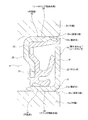
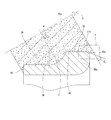
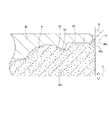
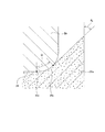
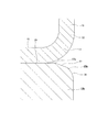
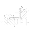
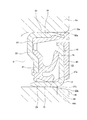
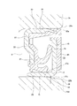
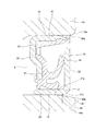
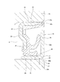
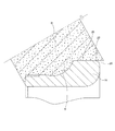
本発明の実施の形態の第1例を示す、図16と同様の図。The figure similar to FIG. 16 which shows the 1st example of embodiment of this invention. 本例の内輪表面の研削方法を示す部分断面図。The fragmentary sectional view which shows the grinding method of the inner ring | wheel surface of this example. 図2のイ部拡大図。FIG. 本例の外輪表面の研削方法を示す部分断面図。The fragmentary sectional view which shows the grinding method of the outer ring | wheel surface of this example. 図4のロ部拡大図。The B section enlarged view of FIG. 本発明の実施の形態の第2例を示す、内輪とスリンガとの嵌合部の軸方向内端部分の拡大断面図。The expanded sectional view of the axial direction inner end part of the fitting part of an inner ring | wheel and slinger which shows the 2nd example of embodiment of this invention. 同第3例を示す、内輪の外周面にスリンガを圧入する直前の状態を示す部分拡大断面図。The partial expanded sectional view which shows the state just before pressing a slinger into the outer peripheral surface of an inner ring | wheel which shows the 3rd example. 同第4例を示す、図1と同様の図。The figure similar to FIG. 1 which shows the 4th example. 同第5例を示す、図1と同様の図。The figure similar to FIG. 1 which shows the same 5th example. 同第5例の変形例を示す、図1と同様の図。The figure similar to FIG. 1 which shows the modification of the said 5th example. 同第5例の別の変形例を示す、図1と同様の図。The figure similar to FIG. 1 which shows another modification of the said 5th example. 同第6例を示す、図1と同様の図。The figure similar to FIG. 1 which shows the 6th example. 同第7例を示す、図1と同様の図。The figure similar to FIG. 1 which shows the said 7th example. 同第7例の変形例を示す、図1と同様の図。The figure similar to FIG. 1 which shows the modification of the said 7th example. 従来構造の1例を示す断面図。Sectional drawing which shows an example of a conventional structure. 図15のハ部拡大図。FIG. 16 is an enlarged view of a portion C in FIG. 15. 従来の内輪表面の研削方法の1例を示す部分断面図。The fragmentary sectional view which shows one example of the grinding method of the conventional inner ring | wheel surface. 従来の外輪表面の研削方法の1例を示す部分断面図。The fragmentary sectional view which shows one example of the grinding method of the conventional outer ring | wheel surface.

[実施の形態の第1例]
図1〜5は、請求項1、2、4、5に対応する、本発明の実施の形態の第1例を示している。尚、本例の特徴は、内輪19aの軸方向内端部外周面の形状と、外輪2aの軸方向内端部内周面の形状と、これらの加工方法とを工夫した点にある。その他の部分の構造及
び作用は、前述の図15〜16に示した従来構造の場合と同様であるから、重複する図示並びに説明は省略若しくは簡略にし、以下、本例の特徴部分を中心に説明する。
[First example of embodiment]
1 to 5 show a first example of an embodiment of the present invention corresponding to claims 1, 2, 4, and 5. FIG. The feature of this example is that the shape of the inner peripheral surface of the inner end portion in the axial direction of the inner ring 19a, the shape of the inner peripheral surface of the inner end portion of the outer ring 2a in the axial direction, and these processing methods are devised. Since the structure and operation of the other parts are the same as those of the conventional structure shown in FIGS. 15 to 16, the overlapping illustrations and explanations are omitted or simplified, and the following description will focus on the features of this example. To do.

本例の場合、前記内輪19aの外周面のうち、軸方向内端部に存在する円筒状のスリンガ用嵌合面20部分と、軸方向内端縁に存在する断面円弧形の面取り部25aの外径側部分(軸方向外側部分)と、これら両部分同士の繋ぎ目27a部分との、互いに連続した部分全体を、断面形状に関して微分不能な(尖った)角部がなく滑らかに連続した研削面(平滑面)としている。この為に本例の場合には、前記内輪19aの製造工程の仕上げ段階(所定の形状及び寸法を得る為の旋削加工と、硬度や靭性を高める為の熱処理とを、順次行った後の段階)で、図2〜3に示す様に、前記内輪19aの表面のうち、軸方向外端面43部分、並びに、軸方向外端寄りに存在するカウンタボア28部分と、内輪軌道5部分と、前記スリンガ用嵌合面20部分と、前記面取り部25aの外径側部分と、これら各部分同士の繋ぎ目29、30、27a部分とから成る、互いに連続した部分とに、総型の回転砥石31aによって、同時に研削加工を施している。   In the case of this example, of the outer peripheral surface of the inner ring 19a, a cylindrical slinger fitting surface 20 portion present at the inner end portion in the axial direction, and a chamfered portion 25a having a circular arc shape existing at the inner end edge in the axial direction. The entire continuous portion of the outer diameter side portion (the axially outer portion) and the joint portion 27a between these two portions is smoothly continuous without any non-differentiable (pointed) corners with respect to the cross-sectional shape. It is a ground surface (smooth surface). For this reason, in the case of the present example, the finishing stage of the manufacturing process of the inner ring 19a (the stage after sequentially performing the turning process for obtaining a predetermined shape and dimensions and the heat treatment for increasing the hardness and toughness) 2), as shown in FIGS. 2 to 3, in the surface of the inner ring 19a, the axial outer end face 43 portion, the counter bore 28 portion located near the axial outer end, the inner ring raceway 5 portion, The rotating grindstone 31a of the total type includes a fitting surface 20 portion for slinger, an outer diameter side portion of the chamfered portion 25a, and joint portions 29, 30, 27a between these portions and continuous portions. The grinding process is performed at the same time.

本例の場合、この回転砥石31aの回転中心軸Xは、前記内輪軌道5を転走する各玉6、6(図15参照)に付与する接触角αの方向と直角な方向に配置し、且つ、前記回転砥石31aの切り込み送り方向は、この接触角αの方向(前記回転中心軸Xと直角な方向)にほぼ一致させている。又、本例の場合には、前記内輪軌道5を、正確な輪郭形状を有し、且つ、後工程である超仕上げで消せる程度の良好な粗さの研削面に加工できる様にすべく、前記回転砥石31aとして、比較的粒度が細かく、結合度の高いものを選択使用している。一般に、この様な回転砥石31aの場合、切り込み送り方向に対する加工面の傾斜角度が45度よりも小さくなると、この加工面に目詰まりが発生し易くなり、この結果、被加工面に研削焼けや研削割れが生じ易くなる。そこで、本例の場合には、前記回転砥石31aの加工面のうち、前記面取り部25aの外径側部分(この面取り部25aのうち、前記切り込み送り方向に対する接線の傾斜角度が45度以上になる部分)と対向する部分(図3の区間P部分)の断面形状のみを、当該外径側部分の断面形状と合致する円弧形状とし、それよりも軸方向内側(図4の右側)の部分の断面形状を、前記切り込み送り方向に対する傾斜角度θaが45度となる直線形状としている。上述した様に、前記回転砥石31aの切り込み送り方向は、前記接触角αの方向にほぼ一致させている。この接触角αは、通常、前記内輪19aの径方向に対して30〜40度程度である。この為、前記面取り部25aの研削範囲は、この面取り部25aの軸方向外端縁から、前記内輪19aの径方向に対して(軸方向内側に向けて)15〜5度程度までの範囲となる。尚、本例の場合には、前記切り込み送り方向に対する、前記スリンガ用嵌合面20の傾斜角度よりも、前記面取り部25aの研削範囲の傾斜角度の方が大きくなる為、この面取り部25aの研削範囲の表面粗さを、前記スリンガ用嵌合面20の表面粗さよりも良好にする事ができる。従って、この面取り部25aの研削範囲に関する、後述するスリンガ13の圧入時の乗り上げガイドとしての機能を高める事ができる。 In the case of this example, the rotation center axis X of the rotating grindstone 31a is arranged in a direction perpendicular to the direction of the contact angle α applied to each ball 6, 6 (see FIG. 15) rolling on the inner ring raceway 5, In addition, the cutting feed direction of the rotating grindstone 31a is substantially matched to the direction of the contact angle α (direction perpendicular to the rotation center axis X). Further, in the case of this example, the inner ring raceway 5 has an accurate contour shape and can be processed into a ground surface having a good roughness enough to be erased by super-finishing which is a subsequent process. As the rotating grindstone 31a, one having a relatively fine particle size and a high degree of bonding is selectively used. In general, in the case of such a rotating grindstone 31a, when the inclination angle of the processed surface with respect to the cutting feed direction is smaller than 45 degrees, the processed surface is likely to be clogged. Grinding cracks are likely to occur. Therefore, in the case of this example, of the processed surface of the rotary grindstone 31a, the outer diameter side portion of the chamfered portion 25a (of the chamfered portion 25a, the inclination angle of the tangent to the cutting feed direction is 45 degrees or more. Only the cross-sectional shape of the portion (section P portion in FIG. 3) facing the cross-sectional shape is an arc shape that matches the cross-sectional shape of the outer-diameter side portion, and the portion on the inner side in the axial direction (right side in FIG. 4) the cross-sectional shape, the inclination angle theta a to said infeed feed direction is a straight line shape which is 45 degrees. As described above, the cutting feed direction of the rotating grindstone 31a is substantially matched with the direction of the contact angle α. The contact angle α is usually about 30 to 40 degrees with respect to the radial direction of the inner ring 19a. For this reason, the grinding range of the chamfered portion 25a is a range from about 15 to 5 degrees from the axial outer end edge of the chamfered portion 25a to the radial direction of the inner ring 19a (inward in the axial direction). Become. In the case of this example, the inclination angle of the grinding range of the chamfer 25a is larger than the inclination angle of the slinger fitting surface 20 with respect to the cutting feed direction. The surface roughness of the grinding range can be made better than the surface roughness of the fitting surface 20 for slinger. Therefore, it is possible to enhance the function as a riding-up guide when the slinger 13 to be described later is press-fitted regarding the grinding range of the chamfered portion 25a.

又、本例の場合、前記外輪2aの内周面のうち、軸方向内端部に存在する円筒状のシールリング用嵌合面24部分と、軸方向内端縁に存在する断面円弧形の面取り部26aの内径側部分(軸方向外側部分)と、これら両部分同士の繋ぎ目32a部分とから成る、互いに連続した部分全体を、断面形状に関して微分不能な(尖った)角部がなく滑らかに連続した平滑面(研削面)としている。この為に本例の場合には、前記外輪2aの製造工程の仕上げ段階(所定の形状及び寸法を得る為の旋削加工と、硬度や靭性を高める為の熱処理とを、順次行った後の段階)で、図4〜5に示す様に、前記外輪2aの表面のうち、軸方向内側の外輪軌道4部分と、軸方向内端寄り部分に存在するカウンタボア33部分と、これら両部分同士の繋ぎ目34部分とから成る、互いに連続した部分、並びに、前記シールリング用嵌合面24部分と、前記面取り部26aの内径側部分と、これら両部分同士の繋ぎ目32a部分とから成る、互いに連続した部分とに、総型の回転砥石35aによって同時に研削加工を施している。   Further, in the case of this example, the cylindrical seal ring fitting surface 24 portion present at the axial inner end portion of the inner peripheral surface of the outer ring 2a and the cross-section arc shape existing at the axial inner end edge. The chamfered portion 26a has an inner diameter side portion (an axially outer portion) and a joint portion 32a between these two portions, and the entire continuous portion has no indistinguishable (pointed) corners with respect to the cross-sectional shape. It is a smooth continuous surface (grinding surface). For this reason, in the case of this example, the finishing stage of the manufacturing process of the outer ring 2a (the stage after sequentially performing the turning process for obtaining the predetermined shape and dimensions and the heat treatment for increasing the hardness and toughness) 4), as shown in FIGS. 4 to 5, the outer ring raceway 4 portion on the inner side in the axial direction, the counter bore 33 portion existing near the inner end in the axial direction, and the two Consecutive parts composed of the joint part 34, the sealing ring fitting surface 24 part, the inner diameter side part of the chamfered part 26a, and the joint part 32a part of these two parts, A continuous portion is simultaneously ground by a rotating grindstone 35a of a total type.

本例の場合、この回転砥石35aの回転中心軸Yは、前記外輪2aの中心軸に対して平行に配置し、且つ、前記回転砥石35aの切り込み送り方向は、前記外輪2aの径方向に一致させている。又、本例の場合には、前記外輪軌道4を、正確な輪郭形状を有し、且つ、後工程である超仕上げで消せる程度の良好な粗さの研削面に加工できる様にすべく、前記回転砥石35aとして、比較的粒度が細かく、結合度の高いものを選択使用している。前述した様に、一般に、この様な回転砥石35aの場合、切り込み送り方向に対する加工面の傾斜角度が45度よりも小さくなると、この加工面に目詰まりが発生し易くなり、被加工面に研削焼けや研削割れと言った不具合が発生し易くなる。そこで、本例の場合には、前記回転砥石35aの加工面のうち、前記面取り部26aの内径側部分(この面取り部26aのうち、前記切り込み送り方向に対する接線の傾斜角度が45度以上になる部分)と対向する部分(図5の区間Q部分)の断面形状のみを、当該内径側部分の断面形状と合致する円弧形状とし、それよりも軸方向内側(図4の右側)の部分の断面形状を、前記切り込み送り方向に対する傾斜角度θbが45度となる直線形状としている。上述した様に、前記回転砥石35aの切り込み送り方向は、前記外輪2aの径方向に一致させている。この為、前記面取り部26aの研削範囲は、この面取り部26aの軸方向外端縁から、前記外輪2aの径方向に対して(軸方向内側に向けて)45度までの範囲となる。尚、本例の場合には、前記切り込み送り方向に対する、前記シールリング用嵌合面24の傾斜角度よりも、前記面取り部26aの研削範囲の傾斜角度の方が大きくなる為、この面取り部26aの研削範囲の表面粗さを、前記シールリング用嵌合面24の表面粗さよりも良好にする事ができる。従って、この面取り部26aの研削範囲に関する、後述するシールリング14の圧入時の乗り上げガイドとしての機能を高める事ができる。 In the case of this example, the rotation center axis Y of the rotating grindstone 35a is arranged in parallel to the center axis of the outer ring 2a, and the cutting feed direction of the rotating grindstone 35a coincides with the radial direction of the outer ring 2a. I am letting. Further, in the case of this example, the outer ring raceway 4 should have an accurate contour shape and can be processed into a ground surface having a good roughness enough to be erased by super finishing which is a subsequent process. As the rotating grindstone 35a, one having a relatively fine particle size and a high degree of bonding is selectively used. As described above, in general, in the case of such a rotating grindstone 35a, if the inclination angle of the processed surface with respect to the cutting feed direction is smaller than 45 degrees, the processed surface is likely to be clogged, and the processed surface is ground. Problems such as burning and grinding cracks are likely to occur. Therefore, in the case of this example, of the processed surface of the rotating grindstone 35a, the inner diameter side portion of the chamfered portion 26a (in this chamfered portion 26a, the inclination angle of the tangent to the cutting feed direction is 45 degrees or more. Only the cross-sectional shape of the portion (section Q portion in FIG. 5) facing the portion) is an arc shape that matches the cross-sectional shape of the inner diameter side portion, and the cross section of the portion on the axially inner side (right side in FIG. 4) the shape, the inclination angle theta b is a straight line shape which is 45 degrees with respect to the cut feed direction. As described above, the cutting feed direction of the rotating grindstone 35a is made to coincide with the radial direction of the outer ring 2a. For this reason, the grinding range of the chamfered portion 26a is a range from the axial outer end edge of the chamfered portion 26a to 45 degrees with respect to the radial direction of the outer ring 2a (inward in the axial direction). In the case of this example, since the inclination angle of the grinding range of the chamfered portion 26a is larger than the inclination angle of the sealing ring fitting surface 24 with respect to the cutting feed direction, the chamfered portion 26a. The surface roughness of the grinding range can be made better than the surface roughness of the sealing ring fitting surface 24. Therefore, it is possible to enhance the function as a riding-up guide when the seal ring 14 described later is pressed in, regarding the grinding range of the chamfered portion 26a.

上述の様に構成する本例の組み合わせシールリング付転がり軸受ユニット及びその製造方法の場合、内輪19aの表面のうち、スリンガ用嵌合面20部分と面取り部25aの外径側部分との繋ぎ目27a部分は、断面形状に関して微分不能な(尖った)角部になっておらず、しかも円周方向のうねりがほぼ存在しない部分になっている。言い換えれば、当該繋ぎ目27a部分は、前記スリンガ用嵌合面20にスリンガ13の円筒部15を圧入する際に、この円筒部15の内周面に軸方向の傷を付けにくい部分になっている。従って、この圧入の際に、この円筒部15の内周面に軸方向の傷が付く事により、前記内輪19aと前記スリンガ13との嵌合部のシール性が損なわれると言った不具合を、発生しにくくできる。更に、前記面取り部25aの外径側部分の表面粗さは、前記スリンガ用嵌合面20の表面粗さよりも良好である為、上述した圧入時に前記面取り部25aの外径側部分で引っ掛かりが生じて、前記スリンガ13の姿勢が傾くと言った不具合が生じる事を回避できる。   In the case of the rolling bearing unit with the combined seal ring and the manufacturing method thereof according to this example configured as described above, the joint between the slinger fitting surface 20 portion and the outer diameter side portion of the chamfered portion 25a in the surface of the inner ring 19a. The 27a portion is not a non-differentiable (pointed) corner with respect to the cross-sectional shape, and is a portion where there is almost no circumferential undulation. In other words, when the cylindrical portion 15 of the slinger 13 is press-fitted into the slinger fitting surface 20, the joint 27 a portion is a portion that is difficult to damage the inner peripheral surface of the cylindrical portion 15 in the axial direction. Yes. Therefore, when this press-fitting is performed, the inner peripheral surface of the cylindrical portion 15 is scratched in the axial direction so that the sealing performance of the fitting portion between the inner ring 19a and the slinger 13 is impaired. Can be difficult to generate. Furthermore, since the surface roughness of the outer diameter side portion of the chamfered portion 25a is better than the surface roughness of the slinger fitting surface 20, the outer diameter side portion of the chamfered portion 25a is caught during the press-fitting described above. It is possible to avoid the occurrence of a problem that the slinger 13 is tilted.

又、本例の場合、外輪2aの表面のうち、シールリング用嵌合面24部分と面取り部26aの内径側部分と繋ぎ目32a部分は、断面形状に関して微分不能な(尖った)角部になっておらず、しかも円周方向のうねりがほぼ存在しない部分になっている。言い換えれば、当該繋ぎ目32a部分は、前記シールリング用嵌合面24にシールリング14を構成する芯金22の円筒部23を圧入する際に、この円筒部23の外周面に軸方向の傷を付けにくい部分になっている。従って、この圧入の際に、この円筒部23の外周面に軸方向の傷が付く事により、前記外輪2aと前記シールリング14との嵌合部のシール性が損なわれると言った不具合を、発生しにくくできる。更に、前記面取り部26aの内径側部分の表面粗さは、前記シールリング用嵌合面24の表面粗さよりも良好である為、上述した圧入時に前記面取り部26aの内径側部分で引っ掛かりが生じて、前記シールリング14の姿勢が傾くと言った不具合が生じる事を回避できる。   In the case of this example, the sealing ring fitting surface 24 portion, the inner diameter side portion of the chamfered portion 26a, and the joint 32a portion of the surface of the outer ring 2a are indifferent (pointed) corner portions with respect to the cross-sectional shape. It does not become a part and there is almost no circumferential undulation. In other words, when the cylindrical portion 23 of the metal core 22 constituting the seal ring 14 is press-fitted into the seal ring fitting surface 24, the joint 32 a portion is damaged in the axial direction on the outer peripheral surface of the cylindrical portion 23. It is difficult to attach. Therefore, in this press-fitting, the outer peripheral surface of the cylindrical portion 23 is scratched in the axial direction, so that the sealing performance of the fitting portion between the outer ring 2a and the seal ring 14 is impaired. Can be difficult to generate. Furthermore, since the surface roughness of the inner diameter side portion of the chamfered portion 26a is better than the surface roughness of the sealing ring fitting surface 24, the inner diameter side portion of the chamfered portion 26a is caught during the press-fitting described above. Thus, it is possible to avoid a problem that the posture of the seal ring 14 is inclined.

尚、上述した第1例の場合には、内輪19aの面取り部25aの研削範囲が、外輪2aの面取り部26aの研削範囲よりも狭くなりがちであるが、この内輪19aの面取り部25aの研削範囲の軸方向内端縁の直径は、少なくとも圧入前のスリンガ13の円筒部15の内径寸法よりも小さくする必要がある。この様な要求に応えられる程、前記内輪19aの面取り部25aの研削範囲を確保できそうにない場合には、前記傾斜角度θaを45度
よりも或る程度(加工面の目詰まりが容易に発生しない程度)小さくしたり、前記内輪19aの面取り部25aの形状や寸法を変更したりして、上述した要求に応えられる様にする。或いは、前記内輪19aの中心軸に対する前記回転砥石31aの回転中心軸の傾斜角度を、上述した第1例の場合よりも小さくしても良い。
In the case of the first example described above, the grinding range of the chamfered portion 25a of the inner ring 19a tends to be narrower than the grinding range of the chamfered portion 26a of the outer ring 2a. The diameter of the inner edge in the axial direction of the range needs to be at least smaller than the inner diameter dimension of the cylindrical portion 15 of the slinger 13 before press-fitting. When it is unlikely that the grinding range of the chamfered portion 25a of the inner ring 19a can be secured to meet such a requirement, the inclination angle θa is set to a certain degree than 45 degrees (the chamfered surface is easily clogged). In order to meet the above-mentioned requirements, the size can be reduced, or the shape and dimensions of the chamfered portion 25a of the inner ring 19a can be changed. Or you may make the inclination-angle of the rotation center axis | shaft of the said rotating grindstone 31a with respect to the center axis | shaft of the said inner ring | wheel 19a smaller than the case of the 1st example mentioned above.

[実施の形態の第2例]
図6は、請求項1、2、4、5に対応する、本発明の実施の形態の第2例を示している。本例の場合、内輪19bの外周面の軸方向内端部に設けた面取り部25bは、この内輪19bの熱処理前の旋削加工によって形成された、内径側の断面円弧形の凸曲面部36と、同じく熱処理後の研削加工によって形成された、外径側の円すい面部37とが組み合わさった、複合曲面となっている。即ち、本例の場合には、前記熱処理前の旋削加工により、断面形状が単一円弧形の面取り部を形成した後、前記熱処理後の研削加工により、この面取り部の外径側部分を前記円すい面部37に仕上げる事によって、前記面取り部25bを形成している。尚、本例の場合も、前記内輪19bの外周面のうち、スリンガ用嵌合面20部分と、前記面取り部25bの外径側部分(前記円すい面部37に仕上げられる部分)と、これら両部分同士の繋ぎ目27a部分とから成る、互いに連続した部分を、総型の回転砥石により同時に研削する事により、この互いに連続した部分全体を、断面形状に関して微分不能な角部がない平滑面としている。この様な構成を有する本例の場合には、前記面取り部25bの外径側部分(研削面)を円すい面部37としている為、この外径側部分の軸方向内端縁の直径を、圧入前のスリンガ13の円筒部15の内径寸法よりも小さくする事が容易となる。その他の構成及び作用は、上述した第1例の場合と同様である。
[Second Example of Embodiment]
FIG. 6 shows a second example of an embodiment of the present invention corresponding to claims 1, 2, 4, and 5. In the case of this example, the chamfered portion 25b provided at the inner end in the axial direction of the outer peripheral surface of the inner ring 19b is a convex curved surface portion 36 having an arcuate cross section on the inner diameter side formed by turning before heat treatment of the inner ring 19b. In addition, a composite curved surface is formed by combining a conical surface portion 37 on the outer diameter side, which is also formed by grinding after heat treatment. That is, in the case of this example, a chamfered portion having a single circular cross section is formed by turning before the heat treatment, and then the outer diameter side portion of the chamfered portion is ground by grinding after the heat treatment. The chamfered portion 25 b is formed by finishing the tapered surface portion 37. Also in the case of this example, of the outer peripheral surface of the inner ring 19b, the slinger fitting surface 20 portion, the outer diameter side portion of the chamfered portion 25b (the portion finished to the conical surface portion 37), and both these portions. By mutually grinding the continuous portions composed of the joint portions 27a with a rotating grindstone of the total type, the entire continuous portions are made smooth surfaces having no differentiable corners with respect to the cross-sectional shape. . In the case of this example having such a configuration, since the outer diameter side portion (grinding surface) of the chamfered portion 25b is a conical surface portion 37, the diameter of the inner edge in the axial direction of the outer diameter side portion is press-fitted. It becomes easy to make it smaller than the inner diameter dimension of the cylindrical portion 15 of the previous slinger 13. Other configurations and operations are the same as those of the first example described above.

[実施の形態の第3例]
図7は、請求項1、2、4、5に対応する、本発明の実施の形態の第3例を示している。本例の場合には、内輪19cの外周面のうち、スリンガ用嵌合面20の軸方向内側隣りに、軸方向内側に向かう程外径寸法が小さくなる円すい面部38を、この円すい面部38の軸方向内側隣りに円筒状の小径段部39を、それぞれ設けている。そして、これらスリンガ用嵌合面20部分と、円すい面部38部分と、小径段部39部分と、これら各部分同士の繋ぎ目40、41部分とから成る、互いに連続した部分を、総型の回転砥石により同時に研削する事により、この互いに連続した部分全体を、断面形状に関して微分不能な角部がない平滑面としている。又、前記スリンガ用嵌合面20の外径寸法Daは、圧入前のスリンガ13の円筒部15の内径寸法Dbよりも、嵌合締め代分だけ大きい(Da>Db)が、前記小径段部39の外径寸法Dcは、圧入前のスリンガ13の円筒部15の内径寸法Dbよりも、僅かに小さい(Dc<Db)。
[Third example of embodiment]
FIG. 7 shows a third example of an embodiment of the present invention corresponding to claims 1, 2, 4, and 5. In the case of the present example, a conical surface portion 38 whose outer diameter dimension decreases toward the inner side in the axial direction on the inner side in the axial direction of the slinger fitting surface 20 on the outer peripheral surface of the inner ring 19c. Cylindrical small-diameter step portions 39 are respectively provided on the inner sides in the axial direction. Then, a continuous portion consisting of the 20 fitting portions for slinger, the conical surface portion 38, the small-diameter step portion 39, and the joints 40 and 41 between these portions is connected to the entire rotation. By grinding simultaneously with a grindstone, this whole continuous part is made into the smooth surface without the corner part which cannot be differentiated regarding cross-sectional shape. Further, the outer diameter dimension D a of the slinger fitting surface 20 is larger than the inner diameter dimension D b of the cylindrical portion 15 of the slinger 13 before press-fitting (D a > D b ). The outer diameter dimension D c of the small diameter step portion 39 is slightly smaller than the inner diameter dimension D b of the cylindrical portion 15 of the slinger 13 before press-fitting (D c <D b ).

この様な構成を有する本例の場合、前記スリンガ用嵌合面20に前記スリンガ13の円筒部15を圧入する際に、前記小径段部39は、この円筒部15の芯出しガイドとして、前記円すい面部38は、この円筒部15の乗り上げガイドとして、それぞれ機能する。特に、本例の場合には、この円筒部15の芯出しガイドである小径段部39が存在する為、この円筒部15の中心軸が圧入の初期段階で傾斜し、この円筒部15の内周面にかじりを起点とした軸方向傷が付くと言った不具合が発生する事を防止できる。又、前記スリンガ用嵌合面20と前記円すい面部38とが、繋ぎ目40部分によって滑らかに繋がっている。この為、圧入時に、この繋ぎ目40部分によって前記円筒部15の内周面に軸方向の傷が付けられる事を防止できる。これと共に、前記円筒部15が前記円すい面部38及び繋ぎ目40部分を通過する際に受ける、径方向外方に向いた力を抑制できる。従って、この通過に伴い、前記円筒部15の直径が軸方向外側に向かう程大きくなると言った態様の塑
性変形が生じる事を十分に抑制でき、この円筒部15の内周面と前記スリンガ用嵌合面20との密着性を良好にできる。その他の構成及び作用は、前述の図1〜5に示した第1例の場合と同様である。
In the case of this example having such a configuration, when the cylindrical portion 15 of the slinger 13 is press-fitted into the fitting surface 20 for the slinger, the small-diameter step portion 39 serves as a centering guide for the cylindrical portion 15. The conical surface portion 38 functions as a ride-up guide for the cylindrical portion 15. In particular, in the case of this example, since there is a small-diameter stepped portion 39 that is a centering guide for the cylindrical portion 15, the central axis of the cylindrical portion 15 is inclined at the initial stage of press-fitting. It is possible to prevent the occurrence of a problem that the peripheral surface is scratched in the axial direction starting from galling. The slinger fitting surface 20 and the conical surface portion 38 are smoothly connected by a joint 40 portion. For this reason, it is possible to prevent the inner peripheral surface of the cylindrical portion 15 from being scratched in the axial direction by the joint 40 at the time of press-fitting. At the same time, it is possible to suppress the radially outward force that the cylindrical portion 15 receives when passing through the conical surface portion 38 and the joint 40. Accordingly, it is possible to sufficiently suppress the occurrence of plastic deformation in such a manner that the diameter of the cylindrical portion 15 increases as it goes outward in the axial direction with this passage, and the inner peripheral surface of the cylindrical portion 15 and the fitting for the slinger Adhesiveness with the mating surface 20 can be improved. Other configurations and operations are the same as those of the first example shown in FIGS.

尚、上述した第3例の内輪19cの軸方向内端部(前記小径段部39を形成した部分)が、外輪の軸方向内端面よりも軸方向内方に突出した構造を有する転がり軸受ユニットの場合には、前記小径段部39(外径寸法Dc)を、前記スリンガ13の圧入治具42{内径寸法Dd(>Dc)}の芯出しガイドとしても機能させる事ができる。 Note that the rolling bearing unit has a structure in which the inner end portion in the axial direction of the inner ring 19c of the third example described above (the portion where the small-diameter stepped portion 39 is formed) protrudes inward in the axial direction from the inner end surface in the axial direction of the outer ring. in the case of, the cylindrical portion 39 (outer diameter D c), the press-fitting jig 42 {inner diameter D d (> D c)} of the slinger 13 can also function as centering guide.

[実施の形態の第4例]
図8は、請求項1〜5に対応する、本発明の実施の形態の第4例を示している。本例の場合には、内輪19aのスリンガ用嵌合面20に、スリンガ13の円筒部15の軸方向外端部及び中間部のみを、軸方向内側から圧入する事により、締り嵌めで外嵌している。即ち、本例の場合には、この様に外嵌した状態で、スリンガ13の円筒部15の内周面と湾曲部17の内周面との繋ぎ目である、スリンガRエンド部44を、前記スリンガ用嵌合面20と面取り部25aとの繋ぎ目27aよりも、軸方向内側(図8の右側)に配置している。この様な構成を有する本例の場合には、前記スリンガ用嵌合面20に、前記スリンガ13の円筒部15の軸方向外端部及び中間部のみを、軸方向内側から圧入する為、この圧入の際、仮に、前記スリンガ用嵌合面20と面取り部25aとの繋ぎ目27a部分によって、前記円筒部15の内周面に軸方向の傷が付けられたとしても、この軸方向の傷が、前記スリンガ用嵌合面20と前記円筒部15との嵌合部を、軸方向に貫通する状態で形成される事はない。即ち、この軸方向の傷の生成は、前記嵌合部の外部空間側の端部(図8の右端部)で止まり、この外部空間に開口しない。従って、前記傷が前記嵌合部を軸方向に貫通し、この嵌合部のシール性が大きく損なわれると言った事態が発生する事を回避できる。
[Fourth Example of Embodiment]
FIG. 8 shows a fourth example of an embodiment of the present invention corresponding to claims 1 to 5. In the case of this example, only the axially outer end portion and the intermediate portion of the cylindrical portion 15 of the slinger 13 are press-fitted into the slinger fitting surface 20 of the inner ring 19a from the inner side in the axial direction, so that the outer fitting is performed. is doing. That is, in the case of this example, the slinger R end portion 44, which is a joint between the inner peripheral surface of the cylindrical portion 15 of the slinger 13 and the inner peripheral surface of the curved portion 17, is fitted in this way. It arrange | positions in the axial direction inner side (right side of FIG. 8) rather than the joint 27a of the said fitting surface 20 for slinger, and the chamfering part 25a. In the case of this example having such a configuration, in order to press-fit only the axially outer end portion and the intermediate portion of the cylindrical portion 15 of the slinger 13 from the axially inner side to the slinger fitting surface 20, Even when the inner circumferential surface of the cylindrical portion 15 is scratched in the axial direction by the joint portion 27a between the slinger fitting surface 20 and the chamfered portion 25a during the press-fitting, the axial scratch However, it is not formed in a state of penetrating the fitting portion between the slinger fitting surface 20 and the cylindrical portion 15 in the axial direction. That is, the generation of the scratch in the axial direction stops at the end portion on the outer space side of the fitting portion (the right end portion in FIG. 8) and does not open into the outer space. Therefore, it can be avoided that the scratch penetrates the fitting portion in the axial direction and the sealing property of the fitting portion is greatly impaired.

又、本例の場合には、前記スリンガ13の円筒部15の軸方向外端部乃至中間部(円輪部16から離れた位置に存在し、剛性がほぼ一様になっている部分)のみを、前記スリンガ用嵌合面20に圧入しており、前記スリンガ13の円筒部15の軸方向内端部(前記円輪部16の近くの位置に存在し、他の部分に比べて剛性が高くなっている部分)を、前記スリンガ用嵌合面20に圧入していない。この為、前記円筒部15とこのスリンガ用嵌合面20との嵌合部の接触面圧を全体的に一様にして、この嵌合部のシール性を良好にできる。これと共に、この嵌合部の接触面圧の勾配に基づく前記円輪部16の倒れを防止して、この円輪部16の表面に摺接するシール部材のシールリップの耐久性が低下する事を防止できる。その他の構成及び作用は、前述の図1〜5に示した第1例の場合と同様である。   Further, in the case of this example, only the axially outer end portion or intermediate portion (the portion that is located away from the annular portion 16 and has a substantially uniform rigidity) of the cylindrical portion 15 of the slinger 13. Is inserted into the slinger fitting surface 20, and is located at the axially inner end of the cylindrical portion 15 of the slinger 13 (located near the annular portion 16 and has rigidity compared to other portions). The heightened portion) is not press-fitted into the slinger fitting surface 20. For this reason, the contact surface pressure of the fitting portion between the cylindrical portion 15 and the slinger fitting surface 20 is made uniform as a whole, and the sealing performance of the fitting portion can be improved. At the same time, the ring portion 16 is prevented from falling due to the gradient of the contact surface pressure of the fitting portion, and the durability of the seal lip of the seal member slidably contacting the surface of the ring portion 16 is reduced. Can be prevented. Other configurations and operations are the same as those of the first example shown in FIGS.

尚、本例の様に、スリンガ13の円筒部15の軸方向内端部を、内輪19aのスリンガ用嵌合面20に圧入しない技術による効果は、繋ぎ目27a部分が尖っている場合でも得られる。   In addition, the effect by the technique which does not press-fit the axial direction inner end part of the cylindrical part 15 of the slinger 13 to the fitting surface 20 for slinger of the inner ring | wheel 19a like this example is acquired even when the joint 27a part is sharp. It is done.

[実施の形態の第5例]
図9は、請求項1〜5に対応する、本発明の実施の形態の第5例を示している。本例の場合も、上述した第4例の場合と同様、内輪19dのスリンガ用嵌合面20に、スリンガ13の円筒部15の軸方向外端部及び中間部のみを、軸方向内側から圧入する事により、締り嵌めで外嵌している。但し、本例の場合には、前述の図6に示した第2例の場合と同様、前記スリンガ用嵌合面20の軸方向内側に隣接する部分に円すい面部37aを設けており、この円すい面部37aの軸方向寸法を大きくする事によって、前記内輪19dの軸方向内端面を、外輪2aの軸方向内端面と面一にし(同一平面上に位置させ)ている。又、前記スリンガ13の円輪部16の内側面には、回転速度検出装置を構成する為の円輪状のエンコーダ45を添着固定すると共に、このエンコーダ45の内側面を、前記外輪2a及び内輪19dの軸方向内端面と面一にしている。本例の場合、これら各面を面一にする事により、量産時の作業性向上を図っている。なお、エンコーダを添着せずにスリンガ13の円輪部16の内側面を、外輪2a及び内輪19dの軸方向内端面と面一にしても良い。いずれにせよ、円すい面部37aを設けることで、スリンガ13の円筒部15の軸方向内端部を内輪19dのスリンガ用嵌合面20に圧入することなく、エンコーダ45または円輪部16の内側面を前記外輪2a及び内輪19dの軸方向内端面と面一にする事で、量産時の作業性を向上することができる。その他の構成及び作用は、上述した各例の場合と同様である。
[Fifth Example of Embodiment]
FIG. 9 shows a fifth example of the embodiment of the invention corresponding to claims 1 to 5. Also in the case of this example, as in the case of the fourth example described above, only the axially outer end portion and the intermediate portion of the cylindrical portion 15 of the slinger 13 are press-fitted from the axially inner side into the slinger fitting surface 20 of the inner ring 19d. By doing so, it is externally fitted with an interference fit. However, in the case of this example, as in the case of the second example shown in FIG. 6 described above, a conical surface portion 37a is provided in a portion adjacent to the inner side in the axial direction of the slinger fitting surface 20, and this conical By increasing the axial dimension of the surface portion 37a, the axial inner end face of the inner ring 19d is flush with the axial inner end face of the outer ring 2a (positioned on the same plane). An annular encoder 45 for constituting a rotational speed detecting device is attached and fixed to the inner side surface of the annular portion 16 of the slinger 13 and the inner side surface of the encoder 45 is connected to the outer ring 2a and the inner ring 19d. It is flush with the axially inner end face. In the case of this example, by making these surfaces flush with each other, workability at the time of mass production is improved. The inner surface of the ring portion 16 of the slinger 13 may be flush with the axial inner end surfaces of the outer ring 2a and the inner ring 19d without attaching an encoder. In any case, by providing the conical surface portion 37a, the inner surface of the encoder 45 or the annular portion 16 can be inserted without press-fitting the axial inner end portion of the cylindrical portion 15 of the slinger 13 into the slinger fitting surface 20 of the inner ring 19d. Is made flush with the axial inner end surfaces of the outer ring 2a and the inner ring 19d, the workability during mass production can be improved. Other configurations and operations are the same as those in the above-described examples.

図10,11は、請求項1〜5に対応する、実施の形態の第5例の変形例を示している。本例の場合、前述の図9と同様に、内輪19dの軸方向内端面を、外輪2aの軸方向内端面と面一にしている。但し、エンコーダ45(図10)又はスリンガ13の円輪部16(図11)の内側面を、前記外輪2a及び内輪19dの軸方向内端面よりも軸方向外側に配置している。本変形例においては、突出した外輪2a及び内輪19dがエンコーダ45又は円輪部16の内側面を保護することにより、組立作業時における不用意な力の入力やエンコーダ45の表面傷を防止することができる。   10 and 11 show a modification of the fifth example of the embodiment corresponding to claims 1 to 5. In the case of this example, as in FIG. 9 described above, the inner end surface in the axial direction of the inner ring 19d is flush with the inner end surface in the axial direction of the outer ring 2a. However, the inner surface of the encoder 45 (FIG. 10) or the ring portion 16 (FIG. 11) of the slinger 13 is disposed on the axially outer side than the axial inner end surfaces of the outer ring 2a and the inner ring 19d. In this modification, the protruding outer ring 2a and inner ring 19d protect the inner surface of the encoder 45 or the annular portion 16, thereby preventing inadvertent input of force during assembly work and surface damage of the encoder 45. Can do.

[実施の形態の第6例]
図12は、請求項1〜5に対応する、本発明の実施の形態の第6例を示している。本例の場合には、内輪19eの外周面のうち、スリンガ用嵌合面20よりも軸方向内側に存在する部分の形状が、前述の図7に示した第3例の場合と同様の形状(円すい面部38及び小径段部39を有する形状)になっている。その他の構成及び作用は、上述した第5例の場合と同様であり、内輪19e及び外輪2aの軸方向内端面とエンコーダ45の内側面とを面一にしている。
[Sixth Example of Embodiment]
FIG. 12 shows a sixth example of an embodiment of the present invention corresponding to claims 1 to 5. In the case of the present example, the shape of the portion of the outer peripheral surface of the inner ring 19e that is on the inner side in the axial direction of the slinger fitting surface 20 is the same shape as in the case of the third example shown in FIG. (A shape having a conical surface portion 38 and a small diameter step portion 39). Other configurations and operations are the same as in the case of the fifth example described above, and the axial inner end surfaces of the inner ring 19e and the outer ring 2a are flush with the inner surface of the encoder 45.

[実施の形態の第7例]
図13は、請求項1〜5に対応する、本発明の実施の形態の第7例を示している。本例の場合、前述した第1例の場合と同様、内輪19aのスリンガ用嵌合面20に、スリンガ13aの円筒部15を軸方向内側から圧入する事により、締り嵌めで外嵌している。但し、スリンガ13aの円筒部15のうち、スリンガRエンド部44から軸方向外側に、軸方向外側に向かう程外形寸法が小さくなるテーパ部47を、このテーパー部47の軸方向外側に円筒部15との繋ぎ目46を、それぞれ設けている。繋ぎ目46とスリンガRエンド部44の間をテーパー形状とすることにより、内輪19aに円すい面部(37a)または小径段部(39)を設けずとも上述した第6例と同様の効果を得ることができる。スリンガ13aは金属板をプレス加工したものであり、テーパー部47もプレス加工により成形されている。
[Seventh example of embodiment]
FIG. 13 shows a seventh example of the embodiment of the invention corresponding to claims 1 to 5. In the case of this example, as in the case of the first example described above, the cylindrical portion 15 of the slinger 13a is press-fitted into the slinger fitting surface 20 of the inner ring 19a from the inner side in the axial direction so as to be externally fitted with an interference fit. . However, of the cylindrical portion 15 of the slinger 13a, the tapered portion 47 whose outer dimension decreases toward the outer side in the axial direction from the slinger R end portion 44 to the outer side in the axial direction, and the cylindrical portion 15 on the outer side in the axial direction of the tapered portion 47. The joint 46 is provided respectively. By forming a taper shape between the joint 46 and the slinger R end portion 44, the same effect as that of the sixth example described above can be obtained without providing the conical surface portion (37a) or the small diameter step portion (39) on the inner ring 19a. Can do. The slinger 13a is obtained by pressing a metal plate, and the tapered portion 47 is also formed by pressing.

図14は、請求項1〜5に対応する、実施の形態の第7例の変形例を示している。本例の場合には、スリンガ13bの円筒部15のうち、前述の図13に示したテーパー部47の形状が、円筒状の段部48となっており、この段部48の軸方向外側に円筒部15との繋ぎ目46を設けている。その他の構成及び作用は、上述した図13の場合と同様であり、スリンガ13bの円筒部15の軸方向内端部を内輪19aのスリンガ用嵌合面20に圧入しないことにより、円筒部15とこのスリンガ用嵌合面20との嵌合部の接触面圧を全体的に一様にして、この嵌合部のシール性を良好にできる。段部48は、バーリング加工のパンチの面取りを、曲げだけ行う場合の適正値より若干小さく設定し、面取りと内径部の境目付近をパンチに引掛け、引き延ばすことで肉を薄く加工することにより成形することができる。   FIG. 14 shows a modification of the seventh example of the embodiment corresponding to claims 1 to 5. In the case of this example, of the cylindrical portion 15 of the slinger 13b, the shape of the tapered portion 47 shown in FIG. 13 is a cylindrical step portion 48, and the step portion 48 is formed on the outer side in the axial direction. A joint 46 with the cylindrical portion 15 is provided. Other configurations and operations are the same as in the case of FIG. 13 described above, and by not press-fitting the axial inner end of the cylindrical portion 15 of the slinger 13b into the slinger fitting surface 20 of the inner ring 19a, The contact surface pressure of the fitting portion with the fitting surface 20 for slinger can be made uniform as a whole, and the sealing performance of the fitting portion can be improved. The stepped portion 48 is formed by setting the chamfering of the punch for burring slightly smaller than the appropriate value when only bending is performed, hooking the punch near the boundary between the chamfering and the inner diameter portion, and stretching it to thin the meat. can do.

尚、本発明を実施する場合、組み合わせシールリングを組み付ける転がり軸受ユニットは、前述の図15に示した内輪回転型のものに限らず、外輪回転型のものであっても良い。   When the present invention is carried out, the rolling bearing unit to which the combination seal ring is assembled is not limited to the inner ring rotating type shown in FIG. 15, but may be an outer ring rotating type.

本発明の組み合わせシールリング付転がり軸受ユニットは、車輪の回転支持に好適に適用できる。   The rolling bearing unit with a combined seal ring of the present invention can be suitably applied to support the rotation of a wheel.

1 転がり軸受ユニット
2、2a 外輪
3 ハブ
4 外輪軌道
5 内輪軌道
6 玉
7 保持器
8 環状空間
9 シールリング
10 組み合わせシールリング
11 シール部材
12 芯金
13 スリンガ
14 シールリング
15 円筒部
16 円輪部
17 湾曲部
18 ハブ本体
19、19a〜19e 内輪
20 スリンガ用嵌合面
21 シール部材
22 芯金
23 円筒部
24 シールリング用嵌合面
25、25a、25b 面取り部
26、26a 面取り部
27、27a 繋ぎ目
28 カウンタボア
29 繋ぎ目
30 繋ぎ目
31、31a 回転砥石
32、32a 繋ぎ目
33 カウンタボア
34 繋ぎ目
35、35a 回転砥石
36 凸曲面部
37、37a 円すい面部
38 円すい面部
39 小径段部
40 繋ぎ目
41 繋ぎ目
42 圧入治具
43 軸方向外端面
44 スリンガRエンド部
45 エンコーダ
46 繋ぎ目
47 テーパー部
48 段部
DESCRIPTION OF SYMBOLS 1 Rolling bearing unit 2, 2a Outer ring 3 Hub 4 Outer ring raceway 5 Inner ring raceway 6 Ball 7 Cage 8 Annular space 9 Seal ring 10 Combination seal ring 11 Seal member 12 Core metal 13 Slinger 14 Seal ring 15 Cylindrical part 16 Annular part 17 Curved portion 18 Hub body 19, 19a to 19e Inner ring 20 Slinger fitting surface 21 Seal member 22 Core 23 Cylindrical portion 24 Seal ring fitting surface 25, 25a, 25b Chamfered portion 26, 26a Chamfered portion 27, 27a Joint 28 Counterbore 29 Joint 30 Joint 31, 31a Rotary grindstone 32, 32a Joint 33 Counterbore 34 Joint 35, 35a Rotary grindstone 36 Convex surface 37, 37a Conical surface 38 Conical surface 39 Small diameter step 40 Joint 41 Joint 42 Press-fitting jig 43 Axial outer end face 4 Slinger R end portion 45 encoder 46 joint 47 tapered portion 48 step portion

Claims (5)

転がり軸受ユニットと、組み合わせシールリングとを備え、
このうちの転がり軸受ユニットは、互いに同心に配置された回転側軌道輪及び静止側軌道輪と、これら回転側軌道輪及び静止側軌道輪の互いに対向する周面にそれぞれ設けられた回転側軌道と静止側軌道との間に転動自在に設けられた複数個の転動体とを備えたものであり、
前記組み合わせシールリングは、前記回転側軌道輪と前記静止側軌道輪との互いに対向する周面同士の間に存在する環状空間の端部開口を塞ぐもので、スリンガと、シールリングとを備え、
このうちのスリンガは、金属板を曲げ成形する事により、全体を、一部に円筒部を含んだ円環状に造られたもので、このうちの円筒部を、前記回転側軌道輪と前記静止側軌道輪とのうちの一方の軌道輪の周面の一部で他方の軌道輪の周面に対向する部分に設けられた円筒状のスリンガ用嵌合面に、このスリンガ用嵌合面の軸方向片側から圧入する事により締り嵌めで嵌合固定しており、
前記シールリングは、円環状の芯金と、この芯金により補強された、弾性材製で円環状のシール部材とを備えたもので、このうちの芯金を前記他方の軌道輪の周面の一部で前記スリンガに対向する部分に嵌合固定すると共に、前記シール部材を構成する複数本のシールリップの先端部を、前記スリンガの表面に全周に亙り摺接させている、
組み合わせシールリング付転がり軸受ユニットに於いて、
前記一方の軌道輪の表面のうち、前記スリンガ用嵌合面部分と、このスリンガ用嵌合面の軸方向片側隣りに存在する別の面部分と、これら両部分同士の繋ぎ目部分とから成る、互いに連続した部分全体が、前記一方の軌道輪の熱処理後に、総型の回転砥石により同時に研削される事により、断面形状に関して微分不能な角部がなく滑らかに連続した平滑面になっている事を特徴とする組み合わせシールリング付転がり軸受ユニット。
It is equipped with a rolling bearing unit and a combination seal ring,
Among these, the rolling bearing unit includes a rotation-side raceway and a stationary-side raceway arranged concentrically with each other, and a rotation-side raceway provided on the circumferential surfaces facing each other of the rotation-side raceway and the stationary-side raceway, respectively. It is provided with a plurality of rolling elements provided so as to freely roll between the stationary side track and
The combined seal ring closes an end opening of an annular space existing between the mutually facing peripheral surfaces of the rotation side raceway and the stationary side raceway, and includes a slinger and a seal ring,
Of these, the slinger is formed by bending a metal plate into an annular shape partially including a cylindrical portion. The cylindrical portion of the slinger is connected to the rotating raceway and the stationary ring. A cylindrical slinger fitting surface provided on a part of the peripheral surface of one of the side race rings and facing the peripheral surface of the other race ring is connected to the slinger fitting surface. It is fitted and fixed with an interference fit by press-fitting from one side in the axial direction.
The seal ring includes an annular cored bar and an elastic sealing member made of an elastic material reinforced by the cored bar, and the cored bar is a peripheral surface of the other race ring. Is fitted and fixed to a part facing the slinger at a part thereof, and the tip ends of a plurality of seal lips constituting the seal member are slidably brought into sliding contact with the entire surface of the slinger.
In rolling bearing units with combined seal rings,
Of the surface of the one of the race rings, the slinger fitting surface portion, another surface portion adjacent to one side in the axial direction of the slinger fitting surface, and a joint portion between these two portions. In addition, the whole continuous part is ground simultaneously with a rotating grindstone after the heat treatment of one of the bearing rings, thereby forming a smooth continuous smooth surface with no differentiable corners with respect to the cross-sectional shape. A rolling bearing unit with a combination seal ring characterized by
シールリングを構成する芯金は、金属板を曲げ成形する事により、全体を、一部に円筒部を含んだ円環状に造られていて、この円筒部を、他方の軌道輪の周面の一部でスリンガに対向する部分に設けられた円筒状のシールリング用嵌合面に、このシールリング用嵌合面の軸方向片側から圧入する事により締り嵌めで嵌合固定しており、前記他方の軌道輪の表面のうち、前記シールリング用嵌合面部分と、このシールリング用嵌合面の軸方向片側隣りに存在する別の面部分と、これら両部分同士の繋ぎ目部分とから成る、互いに連続した部分全体が、前記他方の軌道輪の熱処理後に、総型の回転砥石により同時に研削される事により、断面形状に関して微分不能な角部がなく滑らかに連続した平滑面になっている、請求項1に記載したシールリング付転がり軸受ユニット。   The metal core constituting the seal ring is formed into an annular shape including a cylindrical portion in part by bending a metal plate, and this cylindrical portion is formed on the peripheral surface of the other race ring. It is fitted and fixed with an interference fit by press-fitting from one side in the axial direction of the seal ring fitting surface into a cylindrical seal ring fitting surface provided in a part facing the slinger. Among the surfaces of the other race ring, from the fitting surface portion for the seal ring, another surface portion existing on one side in the axial direction of the fitting surface for the seal ring, and a joint portion between these two portions The entire continuous portion is ground simultaneously with a rotating grindstone after the heat treatment of the other raceway ring, thereby forming a smoothly continuous smooth surface with no indistinguishable corners with respect to the cross-sectional shape. The seal according to claim 1 Grayed rolling bearing unit. スリンガは、円筒部と、この円筒部の軸方向両端縁のうち、この円筒部のスリンガ用嵌合面への圧入方向と反対側の軸方向端縁である軸方向一端縁から他方の軌道輪に向け径方向に折れ曲がった円輪部と、この円輪部と前記円筒部との連続部に存在する断面円弧形の湾曲部とを備えたもので、この円筒部の軸方向他端部及び中間部のみを前記スリンガ用嵌合面に、このスリンガ用嵌合面の軸方向片側から圧入する事により締り嵌めで嵌合固定している、請求項1〜2のうちの何れか1項に記載したシールリング付転がり軸受ユニット。   The slinger has a cylindrical portion and an axial end edge of the cylindrical portion opposite to the press-fitting direction of the cylindrical portion to the slinger fitting surface of the cylindrical portion. The other end of the cylindrical portion in the axial direction, and a circular-arc-shaped curved portion that exists in a continuous portion between the annular portion and the cylindrical portion. And only the intermediate part is fitted and fixed by interference fitting by press-fitting the slinger fitting surface from one axial direction side of the slinger fitting surface. Rolling bearing unit with seal ring described in 1. 転がり軸受ユニットと、組み合わせシールリングとを備え、
このうちの転がり軸受ユニットは、互いに同心に配置された回転側軌道輪及び静止側軌道輪と、これら回転側軌道輪及び静止側軌道輪の互いに対向する周面にそれぞれ設けられた回転側軌道と静止側軌道との間に転動自在に設けられた複数個の転動体とを備えたものであり、
前記組み合わせシールリングは、前記回転側軌道輪と前記静止側軌道輪との互いに対向する周面同士の間に存在する環状空間の端部開口を塞ぐもので、スリンガと、シールリングとを備え、
このうちのスリンガは、金属板を曲げ成形する事により、全体を、一部に円筒部を含んだ円環状に造られたもので、このうちの円筒部を、前記回転側軌道輪と前記静止側軌道輪とのうちの一方の軌道輪の周面の一部で他方の軌道輪の周面に対向する部分に設けられた円筒状のスリンガ用嵌合面に、このスリンガ用嵌合面の軸方向片側から圧入する事により締り嵌めで嵌合固定しており、
前記シールリングは、円環状の芯金と、この芯金により補強された、弾性材製で円環状のシール部材とを備えたもので、このうちの芯金を前記他方の軌道輪の周面の一部で前記スリンガに対向する部分に嵌合固定すると共に、前記シール部材を構成する複数本のシールリップの先端部を、前記スリンガの表面に全周に亙り摺接させている、
組み合わせシールリング付転がり軸受ユニットの製造方法であって、
前記一方の軌道輪の熱処理後に、この一方の軌道輪の表面のうち、前記スリンガ用嵌合面部分と、このスリンガ用嵌合面の軸方向片側隣りに存在する別の面部分と、これら両部分同士の繋ぎ目部分とから成る、互いに連続した部分を、総型の回転砥石により同時に研削する事により、この互いに連続した部分全体を、断面形状に関して微分不能な角部がなく滑らかに連続した平滑面とする、組み合わせシールリング付転がり軸受ユニットの製造方法。
It is equipped with a rolling bearing unit and a combination seal ring,
Among these, the rolling bearing unit includes a rotation-side raceway and a stationary-side raceway arranged concentrically with each other, and a rotation-side raceway provided on the circumferential surfaces facing each other of the rotation-side raceway and the stationary-side raceway, respectively. It is provided with a plurality of rolling elements provided so as to freely roll between the stationary side track and
The combined seal ring closes an end opening of an annular space existing between the mutually facing peripheral surfaces of the rotation side raceway and the stationary side raceway, and includes a slinger and a seal ring,
Of these, the slinger is formed by bending a metal plate into an annular shape partially including a cylindrical portion. The cylindrical portion of the slinger is connected to the rotating raceway and the stationary ring. A cylindrical slinger fitting surface provided on a part of the peripheral surface of one of the side race rings and facing the peripheral surface of the other race ring is connected to the slinger fitting surface. It is fitted and fixed with an interference fit by press-fitting from one side in the axial direction.
The seal ring includes an annular cored bar and an elastic sealing member made of an elastic material reinforced by the cored bar, and the cored bar is a peripheral surface of the other race ring. Is fitted and fixed to a part facing the slinger at a part thereof, and the tip ends of a plurality of seal lips constituting the seal member are slidably brought into sliding contact with the entire surface of the slinger.
A method of manufacturing a rolling bearing unit with a combined seal ring,
After the heat treatment of the one ring, of the surface of the one ring, the slinger fitting surface part, another surface part existing on one side in the axial direction of the slinger fitting surface, and both By grinding the continuous parts that consist of the joint parts of the parts simultaneously with the rotating grindstone of the total type, the whole continuous parts are smoothly continuous without any indistinguishable corners with respect to the cross-sectional shape. A manufacturing method of a rolling bearing unit with a combined seal ring, which is a smooth surface.
製造対象となる組み合わせシールリング付転がり軸受ユニットに関して、シールリングを構成する芯金は、金属板を曲げ成形する事により、全体を、一部に円筒部を含んだ円環状に造られていて、この円筒部を、他方の軌道輪の周面の一部でスリンガに対向する部分に設けられた円筒状のシールリング用嵌合面に、このシールリング用嵌合面の軸方向片側から圧入する事により締り嵌めで嵌合固定しており、
一方の軌道輪の熱処理後にこの一方の軌道輪の一部を滑らかに連続する平滑面とする事に加えて、前記他方の軌道輪の熱処理後に、この他方の軌道輪の表面のうち、前記シールリング用嵌合面部分と、このシールリング用嵌合面の軸方向片側隣りに存在する別の面部分と、これら両部分同士の繋ぎ目部分とから成る、互いに連続した部分を、総型の回転砥石により同時に研削する事により、この互いに連続した部分全体を、断面形状に関して微分不能な角部がなく滑らかに連続した平滑面とする、請求項4に記載した組み合わせシールリング付転がり軸受ユニットの製造方法。
Regarding the rolling bearing unit with a combination seal ring to be manufactured, the core metal constituting the seal ring is formed into an annular shape including a cylindrical portion in part by bending a metal plate, This cylindrical portion is press-fitted from one axial side of the sealing ring fitting surface into a cylindrical sealing ring fitting surface provided in a part of the peripheral surface of the other race ring and facing the slinger. It is fitted and fixed by interference fit.
In addition to making a part of the one raceway a smooth continuous surface after the heat treatment of one of the race rings, the seal of the surface of the other race ring after the heat treatment of the other race ring. A continuous portion consisting of a ring fitting surface portion, another surface portion adjacent to one side of the seal ring fitting surface in the axial direction, and a joint portion between these two portions is connected to the entire mold. The rolling bearing unit with a combined seal ring according to claim 4, wherein by grinding simultaneously with a rotating grindstone, the entire continuous portions are smoothly smooth surfaces having no differentiable corners with respect to the cross-sectional shape. Production method.
JP2010231427A 2010-01-13 2010-10-14 Rolling bearing unit with combination seal ring, and method for manufacturing the same Pending JP2012197801A (en)

Priority Applications (6)

Application Number Priority Date Filing Date Title
JP2010231427A JP2012197801A (en) 2010-10-14 2010-10-14 Rolling bearing unit with combination seal ring, and method for manufacturing the same
EP11732852.6A EP2525110B1 (en) 2010-01-13 2011-01-11 Rolling bearing unit with combination seal ring, and method for manufacturing same
US13/522,058 US8708571B2 (en) 2010-01-13 2011-01-11 Rolling bearing unit with combined seal ring and manufacturing method thereof
PCT/JP2011/050236 WO2011086982A1 (en) 2010-01-13 2011-01-11 Rolling bearing unit with combination seal ring, and method for manufacturing same
CN201180000021.8A CN102239341B (en) 2010-01-13 2011-01-11 Rolling bearing units with combined sealing rings
JP2011549967A JP5565418B2 (en) 2010-01-13 2011-01-11 Rolling bearing unit with combination seal ring

Applications Claiming Priority (1)

Application Number Priority Date Filing Date Title
JP2010231427A JP2012197801A (en) 2010-10-14 2010-10-14 Rolling bearing unit with combination seal ring, and method for manufacturing the same

Publications (1)

Publication Number Publication Date
JP2012197801A true JP2012197801A (en) 2012-10-18

Family

ID=47180252

Family Applications (1)

Application Number Title Priority Date Filing Date
JP2010231427A Pending JP2012197801A (en) 2010-01-13 2010-10-14 Rolling bearing unit with combination seal ring, and method for manufacturing the same

Country Status (1)

Country Link
JP (1) JP2012197801A (en)

Cited By (2)

* Cited by examiner, † Cited by third party
Publication number Priority date Publication date Assignee Title
JP2015222096A (en) * 2014-05-22 2015-12-10 日本精工株式会社 Bearing for idler pulley
JP2015227674A (en) * 2014-05-30 2015-12-17 Ntn株式会社 Bearing device for wheel

Cited By (2)

* Cited by examiner, † Cited by third party
Publication number Priority date Publication date Assignee Title
JP2015222096A (en) * 2014-05-22 2015-12-10 日本精工株式会社 Bearing for idler pulley
JP2015227674A (en) * 2014-05-30 2015-12-17 Ntn株式会社 Bearing device for wheel

Similar Documents

Publication Publication Date Title
JP5565418B2 (en) Rolling bearing unit with combination seal ring
CN206754176U (en) Sealing device and the roller bearing unit with sealing device
CN102171470B (en) Series connection angular contact ball bearing
CN106917824B (en) Rolling bearing
KR102507430B1 (en) Hub unit bearing and manufacturing method therefor, automobile and manufacturing method therefor
JP2015072057A5 (en)
JP2014055651A (en) Sealing device and rolling bearing device including the same
JP2011226576A (en) Rolling bearing unit with sealing seal
JP2000304054A (en) Tapered roller bearing
JP6244959B2 (en) Tapered roller bearing
JP2012197800A (en) Rolling bearing unit with combination seal ring, and method for manufacturing the same
KR101814703B1 (en) Wheel bearing and jointing structure for wheel bearing and drive shaft
JP2017137885A (en) Hub unit bearing and its manufacturing method
CN1849460B (en) Self-aligning roller bearing and method of processing the same
CN111188830B (en) Flanged inner ring for pendulum roller forming operation
JP5810627B2 (en) Tandem angular ball bearings and outer ring side assemblies for tandem angular ball bearings
CN112412972A (en) Method for manufacturing inner ring for hub unit bearing
JP2009115110A (en) Sealing device
JP2013224725A (en) Hub unit bearing
JP4310089B2 (en) Roller bearing
JP7602316B2 (en) Manufacturing method and manufacturing device for wheel bearing device
JP2011247293A (en) Rolling bearing
JP2006349031A (en) Tapered roller bearings
JP2009121560A (en) Shield plate fixing method and rolling bearing
CN111051714A (en) Angular contact ball bearings, bearing units and spindle units