JP2012197826A - Transmission driving device - Google Patents
Transmission driving device Download PDFInfo
- Publication number
- JP2012197826A JP2012197826A JP2011061043A JP2011061043A JP2012197826A JP 2012197826 A JP2012197826 A JP 2012197826A JP 2011061043 A JP2011061043 A JP 2011061043A JP 2011061043 A JP2011061043 A JP 2011061043A JP 2012197826 A JP2012197826 A JP 2012197826A
- Authority
- JP
- Japan
- Prior art keywords
- shift shaft
- actuator
- shaft
- fork
- shift
- Prior art date
- Legal status (The legal status is an assumption and is not a legal conclusion. Google has not performed a legal analysis and makes no representation as to the accuracy of the status listed.)
- Withdrawn
Links
Images



Landscapes
- Gear-Shifting Mechanisms (AREA)
Abstract
Description
この発明は、変速機を駆動するための変速機駆動装置に関する。 The present invention relates to a transmission drive device for driving a transmission.
従来から、マニュアルトランスミッションの変速が自動化された自動制御式マニュアルトランスミッション(Automated Manual Transmission)の変速装置が知られている。このタイプの変速装置は、たとえば平行歯車式の変速機構を含む変速機と、この変速機構を駆動するための変速機駆動装置とを備えている。変速駆動装置は、変速機構にシフト動作を行わせるためのシフト軸を備えている。シフト軸の途中部には、インターナルレバーが一体回転可能にかつ軸方向に移動可能に取り付けられている(たとえば特許文献1参照)。 2. Description of the Related Art Conventionally, there is known an automatic manual transmission (Automated Manual Transmission) transmission in which manual transmission is automated. This type of transmission includes, for example, a transmission including a parallel gear type transmission mechanism, and a transmission drive device for driving the transmission mechanism. The speed change drive device includes a shift shaft for causing the speed change mechanism to perform a shift operation. An internal lever is attached to the middle portion of the shift shaft so as to be integrally rotatable and movable in the axial direction (see, for example, Patent Document 1).
変速機には、シフトフォークが固定された複数本のフォーク軸が、互いに平行に備えられている。各フォーク軸の途中部には、インターナルレバーと係合するためのフォークヘッドが固定されている。セレクト駆動機構が駆動されて、インターナルレバーがフォーク軸に対して軸方向移動させられることにより、インターナルレバーの先端が所要のフォークヘッドに係合し、セレクト動作が達成される。また、シフト駆動機構が駆動されてシフト軸がその中心軸線まわりに回転させられることにより、インターナルレバーがシフト軸の中心軸線まわりに揺動し、これにより、インターナルレバーと係合しているフォークヘッドがフォーク軸の軸方向に移動してシフト動作が達成される。 The transmission is provided with a plurality of fork shafts each having a shift fork fixed in parallel to each other. A fork head for engaging with an internal lever is fixed to the middle part of each fork shaft. When the select drive mechanism is driven and the internal lever is moved in the axial direction with respect to the fork shaft, the tip of the internal lever engages with a required fork head, and the select operation is achieved. Further, when the shift drive mechanism is driven and the shift shaft is rotated around its central axis, the internal lever swings around the central axis of the shift shaft, thereby engaging with the internal lever. The fork head moves in the axial direction of the fork shaft to achieve the shift operation.
また、シフト軸に代えて、インターナルレバーが固定的に取り付けられたシフト軸(このタイプのシフト軸を、以下「シフトセレクト軸」という。)を採用した変速機も提案されている(たとえば特許文献2参照)。このタイプの変速機では、変速機のハウジングにシフトセレクト軸がその軸方向に移動可能に設けられている。セレクト駆動機構が駆動されてインターナルレバーがシフトセレクト軸ごと軸方向移動させられることにより、インターナルレバーが所要のフォークヘッドに係合し、セレクト動作が達成される。また、シフト駆動機構が駆動されてシフトセレクト軸がその中心軸線まわりに回転させられることにより、インターナルレバーがシフト軸の中心軸線まわりに揺動し、これにより、インターナルレバーと係合しているフォークヘッドがフォーク軸の軸方向に移動してシフト動作が達成される。 There has also been proposed a transmission that employs a shift shaft in which an internal lever is fixedly attached (this type of shift shaft is hereinafter referred to as a “shift select shaft”) instead of the shift shaft (for example, a patent). Reference 2). In this type of transmission, a shift select shaft is provided in the transmission housing so as to be movable in the axial direction. When the select drive mechanism is driven and the internal lever is moved in the axial direction together with the shift select shaft, the internal lever is engaged with a required fork head, and the select operation is achieved. In addition, when the shift drive mechanism is driven and the shift select shaft is rotated around its central axis, the internal lever swings around the central axis of the shift shaft, thereby engaging the internal lever. The fork head is moved in the axial direction of the fork shaft to achieve the shift operation.
しかしながら、前述の特許文献1または2の構成では、セレクト操作(フォークヘッドの選択先の切換え。セレクト動作)のために、インターナルレバーあるいはシフトセレクト軸を所定距離だけ、シフト軸あるいはシフトセレクト軸の軸方向に移動させる必要がある。そのため、セレクト操作の実行のためにある程度の時間を要し、これにより、セレクト操作を伴う変速操作に時間を要していた。
However, in the configuration of
そこで、この発明の目的は、セレクト操作に要する時間を大幅に短縮化でき、これにより、変速機の変速操作を短時間で行うことができる変速機駆動装置を提供することである。 SUMMARY OF THE INVENTION An object of the present invention is to provide a transmission drive apparatus that can significantly reduce the time required for a select operation, and thereby can perform a speed change operation of the transmission in a short time.
前記の目的を達成するための請求項1記載の発明は、複数のフォーク軸(10A,10B,10C)と、各フォーク軸の軸方向(M1,M2,M3)途中部に固定的に取り付けられたフォークヘッド(12A,12B,12C)とを有する変速機(2)を駆動するための変速機駆動装置(3)であって、中心軸線(17;17A;17B)を有するシフト軸(15;15A;15B)と、各フォークヘッドに対応して前記シフト軸に設けられたインターナルレバー(16A,16B,16C)とを含み、各インターナルレバーは、前記シフト軸の途中部に固定された本体部(18A,18B,18C)と、前記本体部に、当該本体部に対して前記シフト軸の回転半径方向(M5)に沿って移動可能に支持されたアクチュエータ(19A,19B,19C)と、各アクチュエータを、対応する前記フォークヘッドに係合する係合位置(D1)と、前記係合位置よりも前記回転半径方向の内方に位置し、対応する前記フォークヘッドに係合しない係合解除位置(D2)との間で移動させるアクチュエータ移動手段(22A,22B,22C)と、前記シフト軸を前記中心軸線まわりに回転させる回転駆動手段(23)とを含む、変速機駆動装置である。 In order to achieve the above object, the invention according to claim 1 is fixedly attached to a plurality of fork shafts (10A, 10B, 10C) and in the middle of the axial direction (M1, M2, M3) of each fork shaft. A transmission drive device (3) for driving a transmission (2) having a fork head (12A, 12B, 12C) having a center axis (17; 17A; 17B). 15A; 15B) and an internal lever (16A, 16B, 16C) provided on the shift shaft corresponding to each fork head, and each internal lever is fixed to a middle portion of the shift shaft A main body (18A, 18B, 18C) and an actuator (19A, 19) supported by the main body so as to be movable with respect to the main body along the rotational radius direction (M5) of the shift shaft. , 19C), an engagement position (D1) for engaging each actuator with the corresponding fork head, and an inner position in the rotational radius direction with respect to the engagement position. Transmission including actuator moving means (22A, 22B, 22C) for moving between disengagement positions (D2) that do not match, and rotation drive means (23) for rotating the shift shaft about the central axis It is a drive device.
なお、括弧内の英数字は、後述の実施形態における対応構成要素等を表すが、特許請求の範囲を実施形態に限定する趣旨ではない。
この構成によれば、各インターレバーにおいて、アクチュエータが係合解除位置と係合位置との間で移動可能に設けられている。そのため、アクチュエータの移動により、アクチュエータを、対応するフォークヘッドに係合する状態と、対応するフォークヘッドとの間で係合しない状態とを切り換えることができる。したがって、所要のフォークヘッドに対応するアクチュエータを係合位置に位置させるともに、他のフォークヘッドに対応するアクチュエータを係合解除位置に位置させることにより、インターナルレバーと所要のフォークヘッドとの係合を達成することができ、これにより、フォークヘッドの選択動作(セレクト操作)が達成される。そして、フォークヘッドに係合しているインターナルレバーのアクチュエータを係合位置に保ちつつ、シフト軸をその中心軸線まわりに回転させることにより、インターナルレバーが当該中心軸線まわりに揺動し、インターナルレバーと係合しているフォークヘッドがフォーク軸の軸方向に移動する。これにより、シフト動作が達成される。
In addition, although the alphanumeric characters in parentheses represent corresponding components in the embodiments described later, the scope of the claims is not intended to be limited to the embodiments.
According to this configuration, in each interlever, the actuator is provided so as to be movable between the engagement release position and the engagement position. Therefore, the actuator can be switched between a state where the actuator is engaged with the corresponding fork head and a state where the actuator is not engaged with the corresponding fork head by the movement of the actuator. Therefore, the actuator corresponding to the required fork head is positioned at the engagement position, and the actuator corresponding to the other fork head is positioned at the disengagement position, thereby engaging the internal lever with the required fork head. Thus, the fork head selection operation (select operation) is achieved. Then, while the internal lever actuator engaged with the fork head is kept in the engaged position, the internal lever is swung around the central axis by rotating the shift shaft around the central axis. The fork head engaged with the null lever moves in the axial direction of the fork shaft. Thereby, a shift operation is achieved.
この構成では、アクチュエータの出退動作によってセレクト操作を行うことができるから、シフト軸やインターナルレバーを軸方向移動させる場合と比較して、セレクト操作に要する時間を短縮することができる。これにより、変速機の変速操作を短時間で行うことができる。
請求項2に記載のように、前記アクチュエータ移動手段は電磁ソレノイド(22A,22B,22C)を含んでいてもよい。この場合、前記アクチュエータは、電磁ソレノイドのプランジャ(19A,19B,19C)を含んでいてもよい。
In this configuration, since the select operation can be performed by the retracting operation of the actuator, the time required for the select operation can be shortened compared to the case where the shift shaft and the internal lever are moved in the axial direction. Thereby, the speed change operation of the transmission can be performed in a short time.
As described in
請求項3に記載のように、前記シフト軸(15A)は中空軸であり、前記シフト軸の内部に前記シフト軸と一体回転可能に収容され、当該シフト軸の軸方向(M4)に延びる金属配線(32A,32B,32C,32D)、および前記金属配線と各電磁ソレノイドとを電気的に接続するための接続構造(33A,33B,33C,33D)を有し、前記金属配線および接続構造を介して電源からの電力を前記複数の電磁ソレノイドに給電するための給電機構(30)をさらに含むものであってもよい。
As described in
この構成によれば、電磁ソレノイドには、シフト軸の内部に配設された給電機構を介して給電される。給電機構がシフト軸に一体回転可能に設けられているので、シフト軸および電磁ソレノイドの回転姿勢に関わらず、接続構造と電磁ソレノイドとを接続するために必要な配線の長さが一定である。そのため、シフト軸の回転に伴う配線長さの変化を考慮する必要がないので、電磁ソレノイドの配置レイアウト設計を比較的容易に行うことができる。 According to this configuration, power is supplied to the electromagnetic solenoid via the power supply mechanism disposed inside the shift shaft. Since the power feeding mechanism is provided so as to be integrally rotatable with the shift shaft, the length of the wiring necessary for connecting the connection structure and the electromagnetic solenoid is constant regardless of the rotation posture of the shift shaft and the electromagnetic solenoid. Therefore, it is not necessary to consider the change in the wiring length accompanying the rotation of the shift shaft, so that the layout layout design of the electromagnetic solenoid can be performed relatively easily.
また、請求項4に記載のように、前記シフト軸(15B)の外周に前記シフト軸と一体回転可能に配設され、当該シフト軸の軸方向(M4)に延び、電源からの電力を前記複数の電磁ソレノイドに給電するための金属配線(42A,42B,42C,42D)をさらに含むものであってもよい。
この構成によれば、電磁ソレノイドには、シフト軸の外周に配設された金属配線を介して給電される。金属配線がシフト軸に一体回転可能に設けられているので、シフト軸および電磁ソレノイドの回転姿勢に関わらず、金属配線と電磁ソレノイドとを接続するために必要な配線の長さが一定である。そのため、シフト軸の回転に伴う配線長さの変化を考慮する必要がないので、電磁ソレノイドの配置レイアウト設計を比較的容易に行うことができる。
According to a fourth aspect of the present invention, the shift shaft (15B) is arranged on the outer periphery of the shift shaft so as to be integrally rotatable with the shift shaft, extends in the axial direction (M4) of the shift shaft, It may further include metal wiring (42A, 42B, 42C, 42D) for supplying power to the plurality of electromagnetic solenoids.
According to this configuration, power is supplied to the electromagnetic solenoid via the metal wiring disposed on the outer periphery of the shift shaft. Since the metal wiring is provided on the shift shaft so as to be integrally rotatable, the length of the wiring necessary for connecting the metal wiring and the electromagnetic solenoid is constant regardless of the rotation posture of the shift shaft and the electromagnetic solenoid. Therefore, it is not necessary to consider the change in the wiring length accompanying the rotation of the shift shaft, so that the layout layout design of the electromagnetic solenoid can be performed relatively easily.
また、請求項5記載の発明は、前記アクチュエータ移動手段および前記回転駆動手段を制御する制御手段(24)をさらに含み、前記制御手段は、前記フォークヘッドと係合している前記インターナルレバーの前記アクチュエータを前記係合解除位置に退避させるのと同時に、前記フォークヘッドと係合していない前記インターナルレバーの前記アクチュエータを前記係合位置に進出させるように、前記アクチュエータ移動手段を制御する、請求項1〜4のいずれか一項に記載の変速機駆動装置である。 The invention according to claim 5 further includes control means (24) for controlling the actuator moving means and the rotation driving means, and the control means is configured to control the internal lever engaged with the fork head. Controlling the actuator moving means to retract the actuator of the internal lever not engaged with the fork head to the engagement position at the same time as retracting the actuator to the disengagement position; It is a transmission drive device as described in any one of Claims 1-4.
この構成によれば、アクチュエータの退避動作とアクチュエータの進出動作とが同時に行われるので、セレクト操作をより一層短時間で実行することができる。これにより、変速機の変速操作を、より一層短時間で行うことができる。 According to this configuration, the retracting operation of the actuator and the advancing operation of the actuator are performed at the same time, so that the selection operation can be executed in a shorter time. Thereby, the shifting operation of the transmission can be performed in a shorter time.
以下では、この発明の実施の形態を、添付図面を参照して詳細に説明する。
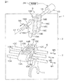
図1は、本発明の一実施形態に係る変速機駆動装置3が適用された変速装置1の概略構成の分解斜視図である。
変速装置1は、変速機2と、変速機2を変速駆動するための変速機駆動装置3とを備えている。
Hereinafter, embodiments of the present invention will be described in detail with reference to the accompanying drawings.
FIG. 1 is an exploded perspective view of a schematic configuration of a transmission 1 to which a
The transmission 1 includes a
変速機2は、公知の常時かみ合い式の平行軸歯車変速機構により構成された動力伝達機構と、動力伝達機構の動力伝達経路を、複数の動力伝達経路の間で切り換えるための変速操作機構6と、これら動力伝達機構および変速操作機構6を収容するギヤハウジング7とを備え、乗用車やトラックなどの車両に搭載される。動力伝達機構における動力伝達経路の切換えにより、動力伝達比を異ならせることができる。
The
変速操作機構6は、ギヤハウジング7内に収容され、互いに平行に延びる複数のフォーク軸10A,10B,10Cを有している。複数のフォーク軸10A,10B,10Cは、軸方向M1,M2,M3から見て一直線上に位置するように並置されている。各フォーク軸10A,10B,10Cの途中部には、変速機駆動装置3によって駆動されるフォークヘッド12A,12B,12Cが固定されている。これらのフォークヘッド12A,12B,12Cは、軸方向M1,M2,M3に関して揃っている。各フォークヘッド12A,12B,12Cは、変速機駆動装置3に対向する対向面13A,13B,13Cを有している。これら対向面13A,13B,13Cは同一平面を有している。各対向面13A,13B,13Cの中央部には、係合凹所14A,14B,14Cが形成されている。また、各フォーク軸10A,10B,10Cには、動力伝達機構の動力伝達経路を切り換えるために操作される被操作部材(図示しない。たとえばクラッチスリーブ)と係合するためのシフトフォーク11が固定されている(図1ではフォーク軸10Aに設けられたシフトフォーク11のみを示す)。シフトフォーク11の軸方向M1,M2,M3移動により、シフトフォーク11を被操作部材に係合させることができ、その被操作部材を駆動することができる。なお、後述する図2には係合凹所14A,14B,14Cとして係合溝が示されているが、係合溝に代えて係合孔を採用してもよいのは言うまでもない。
The speed
変速機駆動装置3は、変速操作機構6にシフト動作を行わせるための円柱状のシフト軸15と、シフト軸15をシフト動作させるための駆動源として用いられる電動アクチュエータ(回転駆動手段)23とを備えている。シフト軸15は、ギヤハウジング7に中心軸線17まわりに回転可能に支持されている。シフト軸15はフォーク軸10A,10B,10Cのそれぞれといわゆる90°の食い違い軸の関係をなす状態に配置されており、中心軸線17を有している。
The
シフト軸15の途中部(ギヤハウジング7内に収容される部分)には、その軸方向M4に並ぶ複数(この実施形態では3つ)のインターナルレバー16A,16B,16Cが設けられている。各インターナルレバー16A,16B,16Cは、フォークヘッド12A,12B,12Cに1対1に対応して設けられている。各インターナルレバー16A,16B,16Cは、対応するフォークヘッド12A,12B,12Cに近接して配置されている。
A plurality (three in this embodiment) of
第1インターナルレバー16Aはフォークヘッド12Aに対応して設けられている。第1インターナルレバー16Aは、シフト軸15に固定されたフレーム(本体部)18Aと、フレーム18Aに対して出退するアクチュエータ19Aとを備えている。アクチュエータ19Aの先端部(図1に示す下端部)は、フォークヘッド12Aの対向面13Aに対向配置されており、対向面13Aに形成された係合凹所14A内に進入してフォークヘッド12Aと係合できるようになっている。
The first
第2インターナルレバー16Bはフォークヘッド12Bに対応して設けられている。第2インターナルレバー16Bは、シフト軸15に固定されたフレーム18Bと、フレーム18Bに対して出退するアクチュエータ19Bとを備えている。アクチュエータ19Bの先端部(図1に示す下端部)は、フォークヘッド12Bの対向面13Bに対向配置されており、対向面13Bに形成された係合凹所14B内に進入してフォークヘッド12Bと係合できるようになっている。
The second
第3インターナルレバー16Cはフォークヘッド12Cに対応して設けられている。第3インターナルレバー16Cは、シフト軸15に固定されたフレーム18Cと、フレーム18Cに対して出退するアクチュエータ19Cとを備えている。アクチュエータ19Cの先端部(図1に示す下端部)は、フォークヘッド12Cの対向面13Cに対向配置されており、対向面13Cに形成された係合凹所14C内に進入してフォークヘッド12Cと係合できるようになっている。
The third
図2は、第1〜第3インターナルレバー16A,16B,16Cおよびフォークヘッド12A,12B,12Cの要部構成を示す断面図である。各インターナルレバー16A,16B,16Cは、プル型の電磁ソレノイド22A,22B,22Cを備えている。電磁ソレノイド22A,22B,22Cは互いに同等の構成であるので、各電磁ソレノイド22A,22B,22Cについて以下では電磁ソレノイド22Aを例に挙げて説明し、電磁ソレノイド22Bおよび電磁ソレノイド22Cの構成の説明を省略する。
FIG. 2 is a cross-sectional view showing the main configuration of the first to third
図2に示すように、電磁ソレノイド22Aは、プランジャ(可動鉄芯)として機能するアクチュエータ19Aと、アクチュエータ19Aと磁芯を構成する固定鉄芯25と、磁芯の周囲を取り囲むように配置された電磁コイル20と、アクチュエータ19A、固定鉄芯25および電磁コイル20を収容するフレーム18Aとを備えている。
フレーム18Aは略箱状をなしており、強磁性体(たとえば鋼)を用いて形成されている。フレーム18Aの基部側がシフト軸15に固定されている。フレーム18Aの先端壁(図2に示す下端壁)には、フォークヘッド12Aの係合凹所14Aに対向する部分に開口21が形成されている。固定鉄芯25は強磁性体(たとえば鋼)を用いて形成されており、フレーム18Aに固定されている。なお、フレーム18Bおよびフレーム18Cは、フレーム18Aと同等の構成であるのは前述の通りである。
As shown in FIG. 2, the
The
アクチュエータ19Aは、シフト軸15の回転半径方向の一方向(より具体的には、変速操作の中立状態では、アクチュエータ19はそのシフト軸15の軸方向M4およびフォーク軸10A,10B,10Cの軸方向M1,M2,M3の双方に直交する方向)M5に沿って延びる長尺部材であり、強磁性体(たとえば鋼)を用いて形成されている。図1ではアクチュエータ19Aとして略角柱状のものを示しているが、棒状であってもよいし、その断面形状が円形のものであってもよい。
アクチュエータ19Aの先端部は、開口21を通ってフレーム18Aの外方に露出し、フォークヘッド12Aの係合凹所14Aに対向している。アクチュエータ19Aは前記の回転半径方向の一方向M5に沿って移動可能に設けられている。また、アクチュエータ19Aの先端部の形状は、対応する係合凹所14Aの底部に応じた形状などに応じて種々の形状を採用することができる。なお、アクチュエータ19Bおよびアクチュエータ19Cは、アクチュエータ19Aと同等の構成であるのは前述の通りである。
The tip of the
電磁コイル20はボビン(図示しない)に銅線などの線材を巻回することにより設けられている。電磁コイル20(の線材)に通電されると、電磁コイル20に磁界が発生する。
電磁ソレノイド22Aは、アクチュエータ19Aを係合位置D1に向けて弾性的に付勢する付勢部材(図示しない)を備えている。電磁コイル20に通電されていない状態では、電磁コイル20に磁界は発生せず、そのため、アクチュエータ19Aは係合位置D1に位置している。一方、電磁コイル20に通電された状態では、電磁コイル20に磁界が発生し、アクチュエータ19Aは固定鉄芯25に吸引されて、付勢部材の付勢力に抗って係合解除位置D2にまで移動する。係合位置D1とは、アクチュエータ19Aの先端部が対応するフォークヘッド12Aの係合凹所14A内に進入し、アクチュエータ19Aがフォークヘッド12Aに係合する位置をいい、係合解除位置D2とは、アクチュエータ19Aの先端部が対応する係合凹所14Aから退避して、アクチュエータ19Aがフォークヘッド12Aに係合しない位置をいう。すなわち電磁コイル20への切電状態と通電状態とを切り換えることにより、アクチュエータ19Aは係合位置D1と係合解除位置D2との間で変位する。
The
The
前述のように電磁ソレノイド22A,22B,22Cは互いに同等の構成である。すなわち、アクチュエータ19Bおよびアクチュエータ19Cも、それぞれ、係合位置D1と係合解除位置D2との間で変位可能に設けられている。なお、図2には、アクチュエータ19Aが係合解除位置D2にあり、アクチュエータ19Bが係合位置D1にあり、また、アクチュエータ19Cが係合解除位置D2にある状態を示している。
As described above, the
フォークヘッド12Aを所要のフォークヘッド(選択先のフォークヘッド)とする場合、変速操作機構6による選択操作(セレクト操作)は、フォークヘッド12Aに対応するアクチュエータ19Aが係合位置D1に位置させられるともに、他のフォークヘッド12B,12Cに対応するアクチュエータ19B,19Cが係合解除位置D2に位置させられることにより達成される。そして、フォークヘッド12Aに係合しているアクチュエータ19Aが係合位置D1に保持させられつつ、シフト軸15がその中心軸線17まわりに回転させられることにより、アクチュエータ19Aが中心軸線17まわりに揺動し、アクチュエータ19Aと係合しているフォークヘッド12Aがフォーク軸10Aの軸方向M1に移動する。これにより、変速操作機構6によるシフト操作が達成される。
When the
図2に示すように、電磁ソレノイド22A,22B,22Cには、ソレノイド駆動回路26が接続されている。ソレノイド駆動回路26には、電源(図示しない)から給電されている。ソレノイド駆動回路26は、電源とグランドとの間に、電磁ソレノイド22Aを駆動するための第1回路(図示しない)、電磁ソレノイド22Bを駆動するための第2回路(図示しない)、および電磁ソレノイド22Cを駆動するための第3回路(図示しない)を並列に接続した構成を有している。
As shown in FIG. 2, a
さらに、この変速機駆動装置3には、ソレノイド駆動回路26内に備えられた各回路(第1、第2および第3回路)の開閉を切り換えるためのリレーなどの切換え機構(図示しない)を駆動するためのリレー駆動部27が備えられている。リレー駆動部27の駆動により、各回路(第1、第2および第3回路)の開閉が切り換えられて、電源からの電力がソレノイド駆動回路26を介して電磁ソレノイド22A,22B,22Cに個別に供給されるようになっている。なお、電磁ソレノイド22A,22B,22Cに対する給電は、たとえばハーネスによる配線などを介して行われている。
Further, the
変速機駆動装置3は、ECU(Electronic Control Unit:電子制御ユニット)を含む制御部(制御手段)24を備えている。ソレノイド駆動回路26、リレー駆動部27および制御部24は、ギヤハウジング7外、より具体的にはたとえば次に述べる電動アクチュエータ23のハウジング内に収容されている。制御部24にはリレー駆動部27が制御対象として接続されている。制御部24は、リレー駆動部27を駆動して、各電磁ソレノイド22A,22B,22Cへの通電/切電を切り換える。また、図1に示すように、制御部24は電動アクチュエータ23の駆動制御も行う。
The
次に、セレクト操作を含む変速操作機構6の変速操作によって動力伝達経路(図示しない)を切り換える場合について検討する。たとえば、動力伝達経路の切換え前にフォーク軸10Aのシフトフォーク11が被操作部材に係合し、動力伝達経路の切換え後に、フォーク軸10Bのシフトフォーク11が被操作部材に係合する場合を例に挙げて説明する。
変速操作の開始タイミングになると、制御部24は電動アクチュエータ23を制御して、シフト軸15を中心軸線17まわりに回転させ、フォーク軸10Aの軸方向M1位置を中立位置(図1に示す位置)に戻させる。これにより、フォーク軸10Aのシフトフォーク11と被操作部材との係合が外れる。
Next, a case where a power transmission path (not shown) is switched by a speed change operation of the speed
At the start timing of the speed change operation, the
次いで、制御部24は電磁ソレノイド22Aを制御して、フォークヘッド12Aに係合していたアクチュエータ19Aを、係合位置D1から係合解除位置D2まで退避させる。これにより、インターナルレバー16Aとフォークヘッド12Aとの係合が解除される。また、制御部24は、電磁ソレノイド22Bを制御して、係合解除位置D2にあったアクチュエータ19Bを係合位置D1まで進出させる。これにより、インターナルレバー16Bとフォークヘッド12Bとを係合させることができる。また、アクチュエータ19Bは係合解除位置D2のまま変位しない。これらアクチュエータ19A,19Bの出退動作によりセレクト操作が達成される。このとき、アクチュエータ19Aの退避動作とアクチュエータ19Bの進出動作とは同時に行われる。
Next, the
次いで、制御部24は、電動アクチュエータ23を駆動してシフト軸15を中心軸線17まわりに回転させ、フォーク軸10Bを軸方向M2移動させる。これにより、フォーク軸10Bのシフトフォーク11が被操作部材に係合し、動力伝達経路の切り換えが達成される。
以上により、この実施形態によれば、アクチュエータ19A,19B,19Cの出退動作によってフォークヘッド12A,12B,12Cのセレクト操作を行うことができるから、シフト軸15やインターナルレバー16A,16B,16Cを軸方向M1,M2,M3移動させる場合と比較して、セレクト操作に要する時間を短縮することができる。しかも、アクチュエータ19Aの退避動作とアクチュエータ19Bの進出動作とが同時に行われるので、セレクト操作をより一層短時間で実行することができる。これにより、変速機2の変速操作を短時間で行うことができる。
Next, the
As described above, according to this embodiment, the fork heads 12A, 12B, and 12C can be selected by moving the
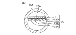
図3は、本発明の他の実施形態に係る変速機駆動装置におけるシフト軸の断面図である。この実施形態において、図1および図2に示す実施形態に示された各部に対応する部分には、図1および図2に示す実施形態と同一の参照符号を付して示し、説明を省略する。図3に示す実施形態が、図1および図2に示す実施形態と相違する点は、シフト軸に関連して設けられた給電機構30を用いて、ギヤハウジング7外のソレノイド駆動回路26から、ギヤハウジング7内の電磁ソレノイド22A,22B,22Cに給電するようにした点である。
FIG. 3 is a cross-sectional view of a shift shaft in a transmission drive apparatus according to another embodiment of the present invention. In this embodiment, parts corresponding to those shown in the embodiment shown in FIGS. 1 and 2 are denoted by the same reference numerals as those in the embodiment shown in FIGS. 1 and 2, and description thereof is omitted. . The embodiment shown in FIG. 3 is different from the embodiment shown in FIGS. 1 and 2 in that the
この実施形態では、図1および図2に示す中実のシフト軸15に代えて中空円筒状のシフト軸15Aを採用している。シフト軸15Aは、中空であること以外はシフト軸15と同等の構成であり、中心軸線17Aを有している。給電機構30はシフト軸15Aの内部に収容され、シフト軸15Aの軸方向M4(図4参照)に沿って延びる長尺の基板31と、基板31上に配置され、シフト軸15Aの軸方向M4に沿って延びる複数本(この実施形態では4本)の金属配線の一例としての銅配線(たとえば銅バスプレート)32A,32B,32C,32Dとを備えている。基板31および銅配線32A,32B,32C,32Dは、シフト軸15Aの内部を、ギヤハウジング7(図1参照)の内外に跨って延びている。
In this embodiment, a hollow
基板31は絶縁材料(ポリフェニレンサルファイド樹脂(PPS)やガラスエポキシ樹脂などの合成樹脂)を用いて形成されている。図3では基板31は平板であり、側端縁がシフト軸15Aの内周壁に固定支持されている。そのため、基板31および銅配線32A,32B,32C,32Dはシフト軸15Aに一体回転可能に設けられている。銅配線32A,32B,32C,32Dは、基板31の一方側主面(シフト軸15Aの中心軸線17A側に対向する面)に配置されている。銅配線32A,32B,32C,32Dはたとえば鋳造により形成されており、互いに間隔を空けて配置されている。これら4本の銅配線32A,32B,32C,32Dは互いに平行に延びている。
The
銅配線32A,32B,32C,32Dの一方側(ギヤハウジング7の外側)端部には、ブラシ機構を介してソレノイド駆動回路26(図2参照)が接続されている。ブラシ機構を介在しているため、銅配線32A,32B,32C,32Dのシフト軸15Aの中心軸線17Aまわりの回転姿勢に関わりなく、銅配線32A,32B,32C,32Dとソレノイド駆動回路26との間の電気的接続は常に保たれている。銅配線32A,32B,32Cはソレノイド駆動回路26を介して電源と接続可能に設けられており、銅配線32Dは、ソレノイド駆動回路26のグランドと接続可能に設けられている。
A solenoid drive circuit 26 (see FIG. 2) is connected to one end (outside of the gear housing 7) of the
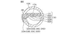
図4は、シフト軸15Aの外周における要部の構成を示す側面図である。図5は、図4の切断面線V−Vから見た断面図である。シフト軸15Aにおけるインターナルレバー16A(図1および図2参照)の近傍位置には、その外周に、複数(この実施形態では4つ)のリード部材(接続構造)33A,33B,33C,33Dがシフト軸15Aの軸方向M4に沿って並置されている。リード部材33A,33B,33C,33Dは、銅配線32A,32B,32C,32Dに1対1に対応付けられている。
FIG. 4 is a side view showing the configuration of the main part on the outer periphery of the
図5に示すように、各リード部材33A,33B,33C,33Dは周方向に長くかつシフト軸15Aの外周面に沿う円弧状の円弧帯状をなしている(図5にはリード部材33Aのみを図示。リード部材33B,33C,33Dはリード部材33Aと同等の構成)。各リード部材33A,33B,33C,33Dは、所定の周方向長さを有している。図4では複数のリード部材33A,33B,33C,33Dを、シフト軸15Aの中心軸線17Aに沿う直線状に並べた構成を示しているが、複数のリード部材33A,33B,33C,33Dはシフト軸15Aの周方向に関してずれていてもよい。図4では、リード部材33D,33C,33B,33Aが電動アクチュエータ23側からこの順に、かつ等間隔を空けて配置された構成を例に挙げているが、リード部材33A,33B,33C,33Dの順序はこの態様に限られず、また、リード部材33A,33B,33C,33Dの配置間隔も等間隔でなくてもよい。
As shown in FIG. 5, each
シフト軸15Aにおける各リード部材33A,33B,33C,33Dの配置位置に関して、中空のシフト軸15Aの内周壁と外周壁とを貫通する貫通孔35(図5には、リード部材33Aの配置位置に形成される貫通孔35のみを図示。)が形成されている。各銅配線32A,32B,32C,32Dにはリード線34A,34B,34C,34Dの一端部が接続されている。リード線34A〜34Dの他端部は、貫通孔35を挿通してシフト軸15Aの外周に引き出され、対応するリード部材33A,33B,33C,33Dに接続されている。これにより、銅配線32A,32B,32C,32Dと、対応するリード部材33A,33B,33C,33Dとが電気的に接続されている。
With respect to the arrangement position of each
リード部材33Aには、たとえば電磁ソレノイド22A(図2参照)の一方側端子が電気的に接続されている。リード部材33Bには、たとえば電磁ソレノイド22B(図2参照)の一方側端子が電気的に接続されている。リード部材33Cには、たとえば電磁ソレノイド22C(図2参照)の一方側端子が電気的に接続されている。リード部材33Dには、たとえば電磁ソレノイド22A,22B,22Cの他方側端子がそれぞれ電気的に接続されている。
For example, one side terminal of an
図2〜図5を参照して、制御部24が、電磁ソレノイド22Aに通電されるようにリレー駆動部27を駆動したときには、電源からの電流が、銅配線32A、リード線34Aおよびリード部材33Aを通って電磁ソレノイド22Aに流れるとともに、リード部材33D、リード線34Dおよび銅配線32Dを通ってグランドに流れる。
また、制御部24が、電磁ソレノイド22Bに通電されるようにリレー駆動部27を駆動したときには、電源からの電流が、銅配線32B、リード線34Bおよびリード部材33Bを通って電磁ソレノイド22Bに流れるとともに、リード部材33D、リード線34Dおよび銅配線32Dを通ってグランドに流れる。
2 to 5, when the
When the
さらに、制御部24が、電磁ソレノイド22Cに通電されるようにリレー駆動部27を駆動したときには、電源からの電流が、銅配線32C、リード線34Cおよびリード部材33Cを通って電磁ソレノイド22Cに流れるとともに、リード部材33D、リード線34Dおよび銅配線32Dを通ってグランドに流れる。
この実施形態(図3〜図5に示す実施形態)によれば、電磁ソレノイド22A,22B,22Cには、ギヤハウジング7外に配置されたソレノイド駆動回路26から、シフト軸15Aの内部に配設された給電機構30を介して給電される。給電機構30がシフト軸15Aに一体回転可能に設けられているので、シフト軸15Aおよび電磁ソレノイド22A,22B,22Cの回転姿勢に関わらず、リード部材33A〜33Dと電磁ソレノイド22A,22B,22Cとを接続するために必要な配線の長さ(この場合リード線34A〜34Dの長さ)が一定である。そのため、変速操作機構6のシフト操作に伴う配線長さの変化を考慮する必要がないので、電磁ソレノイド22A,22B,22Cの配置レイアウト設計を比較的容易に行うことができる。
Further, when the
According to this embodiment (the embodiment shown in FIGS. 3 to 5), the
図6は、本発明のさらに他の実施形態に係る変速機駆動装置におけるシフト軸の断面図である。この実施形態において、図1および図2に示す実施形態に示された各部に対応する部分には、図1および図2に示す実施形態と同一の参照符号を付して示し、説明を省略する。図6に示す実施形態が、図3〜図5に示す実施形態と相違する点は、中空のシフト軸15Aに代えて中実のシフト軸15Bを採用した点である。また、給電機構30に代えて、シフト軸15Bの外周に関連して設けられた給電機構40を採用した点にある。シフト軸15Bはシフト軸15と同等の構成であり、中心軸線17Bを有している。
FIG. 6 is a cross-sectional view of a shift shaft in a transmission drive apparatus according to still another embodiment of the present invention. In this embodiment, parts corresponding to those shown in the embodiment shown in FIGS. 1 and 2 are denoted by the same reference numerals as those in the embodiment shown in FIGS. 1 and 2, and description thereof is omitted. . The embodiment shown in FIG. 6 is different from the embodiment shown in FIGS. 3 to 5 in that a
給電機構40は、シフト軸15Bの外周に配置され、シフト軸15Bの軸方向(図6において紙面に直交する方向)に沿って延びる長尺の基板41と、基板41上に、シフト軸15Bの軸方向に沿って延びる複数本(この実施形態では4本)の金属配線の一例としての銅配線42A,42B,42C,42Dとを備えている。基板41および銅配線42A,42B,42C,42Dは、シフト軸15Bの外周で、ギヤハウジング7(図1参照)の内外に跨って延びている。
The
基板41は絶縁材料(ポリフェニレンサルファイド樹脂(PPS)やガラスエポキシ樹脂などの合成樹脂)を用いて形成されている。図6に示すように基板41はシフト軸15Bの外周に沿う円弧状板であり、シフト軸15Bの外周壁に固定支持されている。そのため、基板41および銅配線42A,42B,42C,42Dはシフト軸15Bに一体回転可能に設けられている。銅配線42A,42B,42C,42Dは、基板41の一方側主面(シフト軸15Bの中心軸線17B側に対向する面)に配置されている。銅配線42A,42B,42C,42Dはたとえば鋳造により形成されており、互いに間隔を空けて配置されている。これら4本の銅配線42A,42B,42C,42Dは互いに平行に延びている。
The
銅配線42A,42B,42C,42Dの一方側(ギヤハウジング7の外側)端部には、ブラシ機構を介してソレノイド駆動回路26(図2参照)が接続されている。銅配線42A,42B,42Cはソレノイド駆動回路26を介して電源と接続可能に設けられており、銅配線42Dは、ソレノイド駆動回路26のグランドと接続可能に設けられている。
銅配線42A,42B,42C,42Dの他方側端部(シフト軸15Bにおけるインターナルレバー16A〜16C近傍位置)には、リード線(図示しない)を介して電磁ソレノイド22A(図2参照)、電磁ソレノイド22B(図2参照)および電磁ソレノイド22C(図2参照)の端子が接続されている。
A solenoid drive circuit 26 (see FIG. 2) is connected to one end (outside of the gear housing 7) of the
An
具体的には、銅配線42Aの他方側端部には、電磁ソレノイド22Aの一方側端子が電気的に接続されている。銅配線42Bの他方側端部には、電磁ソレノイド22Bの一方側端子が電気的に接続されている。銅配線42Cの他方側端部には、電磁ソレノイド22Cの一方側端子が電気的に接続されている。銅配線42Dの他方側端部には、電磁ソレノイド22A,22B,22Cの他方側端子がそれぞれ電気的に接続されている。
Specifically, one end terminal of the
そして、制御部24が、電磁ソレノイド22Aに通電されるようにリレー駆動部27を駆動したときには、電源からの電流が、銅配線42Aおよびリード線を通って電磁ソレノイド22Aに流れるとともに、リード線および銅配線42Dを通ってグランドに流れる。
図2および図6を参照して、制御部24が、電磁ソレノイド22Bに通電されるようにリレー駆動部27を駆動したときには、電源からの電流が、銅配線42Bおよびリード線を通って電磁ソレノイド22Bに流れるとともに、リード線および銅配線42Dを通ってグランドに流れる。
When the
Referring to FIGS. 2 and 6, when
さらに、制御部24が、電磁ソレノイド22Cに通電されるようにリレー駆動部27を駆動したときには、電源からの電流が、銅配線42Cおよびリード線を通って電磁ソレノイド22Cに流れるとともに、リード線および銅配線42Dを通ってグランドに流れる。
この実施形態(図6に示す実施形態)によれば、電磁ソレノイド22A,22B,22Cには、ギヤハウジング7外に配置されたソレノイド駆動回路26から、シフト軸15Bの外周に配設された給電機構40を介して給電される。給電機構40がシフト軸15Bに一体回転可能に設けられているので、シフト軸15Bおよび電磁ソレノイド22A,22B,22Cの回転姿勢に関わらず、銅配線42A〜42Dと電磁ソレノイド22A,22B,22Cとを接続するために必要な配線の長さ(この場合リード線の長さ)が一定である。そのため、変速操作機構6のシフト操作に伴う配線長さの変化を考慮する必要がないので、電磁ソレノイド22A,22B,22Cの配置レイアウト設計を比較的容易に行うことができる。
Further, when the
According to this embodiment (the embodiment shown in FIG. 6), the
以上、この発明の3つの実施形態について説明したが、この発明は他の形態で実施することもできる。たとえば、電磁ソレノイド22A,22B,22Cとして、プル型の電磁ソレノイドを例に挙げたが、プッシュ型の電磁ソレノイドやプッシュプル型の電磁ソレノイドが採用されていてもよい。
また、前述の実施形態では、電磁ソレノイド22A,22B,22Cのプランジャをアクチュエータ19A,19B,19Cとして用いたが、アクチュエータを、電磁ソレノイド22A,22B,22Cのプランジャとは別に設けてもよい。この場合、たとえば、電磁ソレノイド22A,22B,22Cのプランジャの先端部にアクチュエータを配設してもよい。
Although three embodiments of the present invention have been described above, the present invention can be implemented in other forms. For example, as the
In the above-described embodiment, the plungers of the
また、ソレノイド駆動回路26やリレー駆動部27、制御部24がギヤハウジング7内に収容されていてもよい。
また、アクチュエータ19A,19B,19Cを駆動する駆動部材として、電磁ソレノイド22A,22B,22Cに代えて、モータその他の駆動部材を採用できるのは言うまでもない。
Further, the
Further, it goes without saying that motors or other driving members can be employed as the driving members for driving the
また、給電機構30,40に金属配線として銅配線を例に挙げたが、その他の導電材料を用いて配線を形成することもできる。
また、前述したように、電磁ソレノイド22A〜22Cへの給電構造としてハーネスによる配線などを採用してもよいのは言うまでもない。
その他、特許請求の範囲に記載された事項の範囲で種々の設計変更を施すことが可能である。
Moreover, although copper wiring was mentioned as an example in the
Further, as described above, it goes without saying that wiring by a harness or the like may be adopted as a power feeding structure to the
In addition, various design changes can be made within the scope of matters described in the claims.
3…変速機駆動装置、6…変速操作機構、7…ギヤハウジング、10A,10B,10C…フォーク軸、12A,12B,12C…フォークヘッド、15…シフト軸、15A…シフト軸、15B…シフト軸、16A,16B,16C…インターナルレバー、17…中心軸線、17A…中心軸線、17B…中心軸線、18A,18B,18C…フレーム(本体部)、19A,19B,19C…アクチュエータ(プランジャ)、22A,22B,22C…電磁ソレノイド、23…電動アクチュエータ(回転駆動手段)、24…制御部(制御手段)、30…給電機構、32A,32B,32C,32D…銅配線(金属配線)、33A,33B,33C,33D…リード部材(接続構造)、42A,42B,42C,42D…銅配線(金属配線)、D1…係合位置、D2…係合解除位置、M1…(フォーク軸10Aの)軸方向、M2…(フォーク軸10Bの)軸方向、M3…(フォーク軸10Cの)軸方向、M4…(シフトセレクト軸15,15Aの)軸方向、M5…前記回転半径方向の一方向
DESCRIPTION OF
Claims (5)
中心軸線を有するシフト軸と、
各フォークヘッドに対応して前記シフト軸に設けられたインターナルレバーとを含み、
各インターナルレバーは、前記シフト軸の途中部に固定された本体部と、前記本体部に、当該本体部に対して前記シフト軸の回転半径方向に沿って移動可能に支持されたアクチュエータと、
各アクチュエータを、対応する前記フォークヘッドに係合する係合位置と、前記係合位置よりも前記回転半径方向の内方に位置し、対応する前記フォークヘッドに係合しない係合解除位置との間で移動させるアクチュエータ移動手段と、
前記シフト軸を前記中心軸線まわりに回転させる回転駆動手段と
を含む、変速機駆動装置。 A transmission drive device for driving a transmission having a plurality of fork shafts and a fork head fixedly attached to an axial middle portion of each fork shaft,
A shift axis having a central axis;
Including an internal lever provided on the shift shaft corresponding to each fork head,
Each internal lever includes a main body fixed to a middle portion of the shift shaft, and an actuator supported on the main body so as to be movable along the rotational radius direction of the shift shaft with respect to the main body.
An engagement position where each actuator is engaged with the corresponding fork head, and an engagement release position which is located inward in the rotational radial direction from the engagement position and does not engage with the corresponding fork head. An actuator moving means for moving between,
And a rotation driving means for rotating the shift shaft around the central axis.
前記シフト軸の内部に前記シフト軸と一体回転可能に収容され、当該シフト軸の軸方向に延びる金属配線、および前記金属配線と各電磁ソレノイドとを電気的に接続するための接続構造を有し、前記金属配線および接続構造を介して電源からの電力を前記複数の電磁ソレノイドに給電するための給電機構をさらに含む、請求項1または2記載の変速機駆動装置。 The shift shaft is a hollow shaft;
The shift shaft includes a metal wire that is rotatably accommodated with the shift shaft and extends in the axial direction of the shift shaft, and a connection structure for electrically connecting the metal wire and each electromagnetic solenoid. The transmission drive device according to claim 1, further comprising a power feeding mechanism for feeding power from a power source to the plurality of electromagnetic solenoids through the metal wiring and the connection structure.
前記制御手段は、前記フォークヘッドと係合している前記インターナルレバーの前記アクチュエータを前記係合解除位置に退避させるのと同時に、前記フォークヘッドと係合していない前記インターナルレバーの前記アクチュエータを前記係合位置に進出させるように、前記アクチュエータ移動手段を制御する、請求項1〜4のいずれか一項に記載の変速機駆動装置。 And further comprising control means for controlling the actuator moving means and the rotation driving means,
The control means retracts the actuator of the internal lever engaged with the fork head to the disengagement position, and at the same time the actuator of the internal lever not engaged with the fork head The transmission driving device according to any one of claims 1 to 4, wherein the actuator moving means is controlled so that the actuator moves to the engagement position.
Priority Applications (1)
| Application Number | Priority Date | Filing Date | Title |
|---|---|---|---|
| JP2011061043A JP2012197826A (en) | 2011-03-18 | 2011-03-18 | Transmission driving device |
Applications Claiming Priority (1)
| Application Number | Priority Date | Filing Date | Title |
|---|---|---|---|
| JP2011061043A JP2012197826A (en) | 2011-03-18 | 2011-03-18 | Transmission driving device |
Publications (1)
| Publication Number | Publication Date |
|---|---|
| JP2012197826A true JP2012197826A (en) | 2012-10-18 |
Family
ID=47180275
Family Applications (1)
| Application Number | Title | Priority Date | Filing Date |
|---|---|---|---|
| JP2011061043A Withdrawn JP2012197826A (en) | 2011-03-18 | 2011-03-18 | Transmission driving device |
Country Status (1)
| Country | Link |
|---|---|
| JP (1) | JP2012197826A (en) |
Cited By (1)
| Publication number | Priority date | Publication date | Assignee | Title |
|---|---|---|---|---|
| JP2022520796A (en) * | 2019-02-12 | 2022-04-01 | クノル-ブレムゼ ジステーメ フューア ヌッツファールツォイゲ ゲゼルシャフト ミット ベシュレンクテル ハフツング | Shift member for vehicle transmission |
-
2011
- 2011-03-18 JP JP2011061043A patent/JP2012197826A/en not_active Withdrawn
Cited By (1)
| Publication number | Priority date | Publication date | Assignee | Title |
|---|---|---|---|---|
| JP2022520796A (en) * | 2019-02-12 | 2022-04-01 | クノル-ブレムゼ ジステーメ フューア ヌッツファールツォイゲ ゲゼルシャフト ミット ベシュレンクテル ハフツング | Shift member for vehicle transmission |
Similar Documents
| Publication | Publication Date | Title |
|---|---|---|
| US8893674B2 (en) | Valve drive train device | |
| KR101109099B1 (en) | Power switchgear with malfunction prevention function | |
| US9964190B2 (en) | Gear shift operation mechanism | |
| CN107631020B (en) | Gear actuator for dual clutch transmission | |
| JP2016100264A (en) | Electromagnetic switch for starter | |
| JP2008301626A (en) | Rotary actuator device | |
| JP6225710B2 (en) | Electromagnetic actuator | |
| JP2008300404A (en) | Solenoid device | |
| JP2019140207A (en) | Electromagnet device and magnetic relay | |
| EP3557098B1 (en) | Driving module and transmission | |
| JP2012052648A (en) | Transmission driving device | |
| JP6423962B2 (en) | Electromagnetic switch and engine starting device | |
| JP2013162098A (en) | Lock device and driving device | |
| KR102125874B1 (en) | Stator and motor including the same | |
| JP2016074351A (en) | Key interlock device | |
| JP6382161B2 (en) | Engine starter | |
| JP2018041911A (en) | solenoid | |
| JP5698162B2 (en) | Drive device | |
| JP2018142502A (en) | Electromagnetic relay | |
| CN105207417A (en) | Starter Motor | |
| JP2014096516A (en) | Coil winding method and coil unit | |
| KR102754188B1 (en) | Power module and transmission | |
| CN118306577A (en) | Onboard electric servo device | |
| JP2016208700A (en) | Actuator device | |
| JP3194414U (en) | Electromagnetic clutch |
Legal Events
| Date | Code | Title | Description |
|---|---|---|---|
| A300 | Withdrawal of application because of no request for examination |
Free format text: JAPANESE INTERMEDIATE CODE: A300 Effective date: 20140603 |