JP2012197937A - 液圧式の制御弁装置 - Google Patents
液圧式の制御弁装置 Download PDFInfo
- Publication number
- JP2012197937A JP2012197937A JP2012063458A JP2012063458A JP2012197937A JP 2012197937 A JP2012197937 A JP 2012197937A JP 2012063458 A JP2012063458 A JP 2012063458A JP 2012063458 A JP2012063458 A JP 2012063458A JP 2012197937 A JP2012197937 A JP 2012197937A
- Authority
- JP
- Japan
- Prior art keywords
- control
- valve
- line
- counter balance
- hydraulic cylinder
- Prior art date
- Legal status (The legal status is an assumption and is not a legal conclusion. Google has not performed a legal analysis and makes no representation as to the accuracy of the status listed.)
- Granted
Links
Images
Classifications
-
- F—MECHANICAL ENGINEERING; LIGHTING; HEATING; WEAPONS; BLASTING
- F15—FLUID-PRESSURE ACTUATORS; HYDRAULICS OR PNEUMATICS IN GENERAL
- F15B—SYSTEMS ACTING BY MEANS OF FLUIDS IN GENERAL; FLUID-PRESSURE ACTUATORS, e.g. SERVOMOTORS; DETAILS OF FLUID-PRESSURE SYSTEMS, NOT OTHERWISE PROVIDED FOR
- F15B11/00—Servomotor systems without provision for follow-up action; Circuits therefor
- F15B11/003—Systems with load-holding valves
-
- F—MECHANICAL ENGINEERING; LIGHTING; HEATING; WEAPONS; BLASTING
- F15—FLUID-PRESSURE ACTUATORS; HYDRAULICS OR PNEUMATICS IN GENERAL
- F15B—SYSTEMS ACTING BY MEANS OF FLUIDS IN GENERAL; FLUID-PRESSURE ACTUATORS, e.g. SERVOMOTORS; DETAILS OF FLUID-PRESSURE SYSTEMS, NOT OTHERWISE PROVIDED FOR
- F15B2211/00—Circuits for servomotor systems
- F15B2211/30—Directional control
- F15B2211/305—Directional control characterised by the type of valves
- F15B2211/30505—Non-return valves, i.e. check valves
- F15B2211/30515—Load holding valves
-
- F—MECHANICAL ENGINEERING; LIGHTING; HEATING; WEAPONS; BLASTING
- F15—FLUID-PRESSURE ACTUATORS; HYDRAULICS OR PNEUMATICS IN GENERAL
- F15B—SYSTEMS ACTING BY MEANS OF FLUIDS IN GENERAL; FLUID-PRESSURE ACTUATORS, e.g. SERVOMOTORS; DETAILS OF FLUID-PRESSURE SYSTEMS, NOT OTHERWISE PROVIDED FOR
- F15B2211/00—Circuits for servomotor systems
- F15B2211/50—Pressure control
- F15B2211/505—Pressure control characterised by the type of pressure control means
- F15B2211/50509—Pressure control characterised by the type of pressure control means the pressure control means controlling a pressure upstream of the pressure control means
- F15B2211/50518—Pressure control characterised by the type of pressure control means the pressure control means controlling a pressure upstream of the pressure control means using pressure relief valves
- F15B2211/50527—Pressure control characterised by the type of pressure control means the pressure control means controlling a pressure upstream of the pressure control means using pressure relief valves using cross-pressure relief valves
-
- F—MECHANICAL ENGINEERING; LIGHTING; HEATING; WEAPONS; BLASTING
- F15—FLUID-PRESSURE ACTUATORS; HYDRAULICS OR PNEUMATICS IN GENERAL
- F15B—SYSTEMS ACTING BY MEANS OF FLUIDS IN GENERAL; FLUID-PRESSURE ACTUATORS, e.g. SERVOMOTORS; DETAILS OF FLUID-PRESSURE SYSTEMS, NOT OTHERWISE PROVIDED FOR
- F15B2211/00—Circuits for servomotor systems
- F15B2211/70—Output members, e.g. hydraulic motors or cylinders or control therefor
- F15B2211/705—Output members, e.g. hydraulic motors or cylinders or control therefor characterised by the type of output members or actuators
- F15B2211/7051—Linear output members
- F15B2211/7053—Double-acting output members
Landscapes
- Engineering & Computer Science (AREA)
- Physics & Mathematics (AREA)
- Fluid Mechanics (AREA)
- Mechanical Engineering (AREA)
- General Engineering & Computer Science (AREA)
- Fluid-Pressure Circuits (AREA)
Abstract
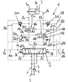
【解決手段】複動式の液圧シリンダ7を制御するための制御弁装置1であって、制御弁2がポンプ4の搬送管路3、タンク5に通じるタンク管路6及び液圧シリンダ7に通じる消費機管路8a,8bと接続され、制御液圧PA;PBによって制御位置2b;2cに向かって操作され、該制御位置において消費機管路8a;8bが、搬送管路に接続された供給側か流出側を形成し、消費機管路にカウンタバランス弁15a,15bが液圧シリンダ7の遮断のために配置され、該カウンタバランス弁は遮断位置16a,16bと貫流位置18a,18bとを有し、流出側に配置されたカウンタバランス弁は、制御弁の制御液圧PA;PBによって貫流位置18b;18aに向かって操作可能である。
【選択図】図1
Description
Claims (4)
- 複動式の液圧シリンダ(7)を制御するための液圧式の制御弁装置(1)であって、中間位置において絞り作用を有する制御弁(2)が設けられていて、該制御弁(2)は、ポンプ(4)の搬送管路(3)、タンク(5)に通じるタンク管路(6)及び液圧シリンダ(7)に通じる消費機管路(8a,8b)と接続されており、制御弁(2)は、各1つの制御液圧(PA;PB)によって1つの制御位置(2b;2c)に向かって操作されるようになっており、該制御位置(2b;2c)において1つの消費機管路(8a;8b)が、搬送管路(3)に接続された供給側を形成し、かつ別の消費機管路(8b;8a)は、タンク(5)に接続された流出側を形成しており、消費機管路(8a,8b)には、弁座シール作用を有する各1つのカウンタバランス弁(15a,15b)が液圧シリンダ(7)のリークオイルのない遮断のために配置されており、該カウンタバランス弁(15a,15b)は漏れのない遮断位置(16a,16b)と貫流位置(18a,18b)とを有している形式のものにおいて、流出側に配置された弁座シール作用を有するカウンタバランス弁(15b;15a)は、制御弁(2)の制御液圧(PA;PB)によって貫流位置(18b;18a)に向かって操作可能であることを特徴とする、液圧式の制御弁装置。
- 負の負荷が液圧シリンダ(7)に作用した場合に、液圧シリンダ(7)の供給側における供給圧に関連して、カウンタバランス弁(15b,15a)を貫流位置へと負荷する制御液圧(PA;PB)に影響を及ぼすことができる、請求項1記載の制御弁装置。
- カウンタバランス弁(15b,15a)を操作するためにパイロット制御管路(20a;20b)が設けられていて、該パイロット制御管路(20a;20b)は、カウンタバランス弁(15b;15a)の、貫流位置(18b;18a)に向かって作用する制御面から延びて、制御弁(2)の制御液圧(PA;PB)を導く制御圧管路(10a;10b)へと接続されており、しかもパイロット制御管路(20a;20b)には絞り装置(21a,21b)が配置されていて、パイロット制御管路(20a;20b)は絞り装置(21a;21b)とカウンタバランス弁(15b;15a)との間において、供給側に通じる流出管路(22a;22b)と接続されており、該流出管路(22a;22b)内に別の絞り装置(23a;23b)が配置され、かつ該別の絞り装置(23a;23b)の下流に、供給側に向かって開放する遮断弁(24a;24b)が配置されている、請求項1又は2記載の制御弁装置。
- 絞り装置(21a;21b;23a;23b)がオリフィス又はノズルとして形成されている、請求項3記載の制御弁装置。
Applications Claiming Priority (2)
| Application Number | Priority Date | Filing Date | Title |
|---|---|---|---|
| DE201110014685 DE102011014685A1 (de) | 2011-03-22 | 2011-03-22 | Hydraulische Steuerventileinrichtung |
| DE102011014685.7 | 2011-03-22 |
Publications (2)
| Publication Number | Publication Date |
|---|---|
| JP2012197937A true JP2012197937A (ja) | 2012-10-18 |
| JP5959252B2 JP5959252B2 (ja) | 2016-08-02 |
Family
ID=45841217
Family Applications (1)
| Application Number | Title | Priority Date | Filing Date |
|---|---|---|---|
| JP2012063458A Active JP5959252B2 (ja) | 2011-03-22 | 2012-03-21 | 液圧式の制御弁装置 |
Country Status (4)
| Country | Link |
|---|---|
| EP (1) | EP2503161B1 (ja) |
| JP (1) | JP5959252B2 (ja) |
| CN (1) | CN102691683B (ja) |
| DE (1) | DE102011014685A1 (ja) |
Cited By (7)
| Publication number | Priority date | Publication date | Assignee | Title |
|---|---|---|---|---|
| WO2015031821A1 (en) * | 2013-08-30 | 2015-03-05 | Eaton Corporation | Control method and system for using a pair of independent hydraulic metering valves to reduce boom oscillations |
| WO2016011193A1 (en) * | 2014-07-15 | 2016-01-21 | Eaton Corporation | Methods and apparatus to enable boom bounce reduction and prevent un-commanded motion in hydraulic systems |
| US9810242B2 (en) | 2013-05-31 | 2017-11-07 | Eaton Corporation | Hydraulic system and method for reducing boom bounce with counter-balance protection |
| US10316929B2 (en) | 2013-11-14 | 2019-06-11 | Eaton Intelligent Power Limited | Control strategy for reducing boom oscillation |
| US10344783B2 (en) | 2013-11-14 | 2019-07-09 | Eaton Intelligent Power Limited | Pilot control mechanism for boom bounce reduction |
| US11204048B2 (en) | 2017-04-28 | 2021-12-21 | Eaton Intelligent Power Limited | System for damping mass-induced vibration in machines having hydraulically controlled booms or elongate members |
| US11209028B2 (en) | 2017-04-28 | 2021-12-28 | Eaton Intelligent Power Limited | System with motion sensors for damping mass-induced vibration in machines |
Citations (4)
| Publication number | Priority date | Publication date | Assignee | Title |
|---|---|---|---|---|
| JPH0231085A (ja) * | 1988-02-25 | 1990-02-01 | Bennies Marrel | 油圧容器用の安全弁とそれを備える油圧回路 |
| JP2001002371A (ja) * | 1999-06-25 | 2001-01-09 | Kobe Steel Ltd | 建設機械のアクチュエータ駆動装置 |
| JP2002022054A (ja) * | 2000-07-05 | 2002-01-23 | Hitachi Constr Mach Co Ltd | 方向制御弁 |
| JP2008039042A (ja) * | 2006-08-04 | 2008-02-21 | Hitachi Constr Mach Co Ltd | 油圧アクチュエータ回路の負荷保持装置 |
Family Cites Families (6)
| Publication number | Priority date | Publication date | Assignee | Title |
|---|---|---|---|---|
| JPS6424163U (ja) * | 1987-08-03 | 1989-02-09 | ||
| DE10224731B4 (de) | 2001-06-29 | 2012-09-20 | Linde Material Handling Gmbh | Hydrostatisches Antriebssystem |
| US6912849B2 (en) * | 2002-04-09 | 2005-07-05 | Komatsu Ltd. | Cylinder driving system and energy regenerating method thereof |
| DE10253340B4 (de) * | 2002-04-26 | 2007-02-15 | Volkmann Gmbh | Betätigungsventil für einen zweiseitig wirksamen Pneumatikzylinder sowie Verwendung eines solchen Betätigungsventils für mittels Pneumatikzylindern ansteuerbare Spulengatter |
| JP3776067B2 (ja) * | 2002-08-12 | 2006-05-17 | 株式会社クボタ | 水田作業機の昇降装置 |
| WO2009102740A2 (en) * | 2008-02-12 | 2009-08-20 | Parker-Hannifin Corporation | Flow management system for hydraulic work machine |
-
2011
- 2011-03-22 DE DE201110014685 patent/DE102011014685A1/de not_active Withdrawn
-
2012
- 2012-02-28 CN CN201210055999.0A patent/CN102691683B/zh not_active Expired - Fee Related
- 2012-03-01 EP EP12157756.3A patent/EP2503161B1/de active Active
- 2012-03-21 JP JP2012063458A patent/JP5959252B2/ja active Active
Patent Citations (4)
| Publication number | Priority date | Publication date | Assignee | Title |
|---|---|---|---|---|
| JPH0231085A (ja) * | 1988-02-25 | 1990-02-01 | Bennies Marrel | 油圧容器用の安全弁とそれを備える油圧回路 |
| JP2001002371A (ja) * | 1999-06-25 | 2001-01-09 | Kobe Steel Ltd | 建設機械のアクチュエータ駆動装置 |
| JP2002022054A (ja) * | 2000-07-05 | 2002-01-23 | Hitachi Constr Mach Co Ltd | 方向制御弁 |
| JP2008039042A (ja) * | 2006-08-04 | 2008-02-21 | Hitachi Constr Mach Co Ltd | 油圧アクチュエータ回路の負荷保持装置 |
Cited By (17)
| Publication number | Priority date | Publication date | Assignee | Title |
|---|---|---|---|---|
| US10502239B2 (en) | 2013-05-31 | 2019-12-10 | Eaton Intelligent Power Limited | Hydraulic system and method for reducing boom bounce with counter-balance protection |
| US9810242B2 (en) | 2013-05-31 | 2017-11-07 | Eaton Corporation | Hydraulic system and method for reducing boom bounce with counter-balance protection |
| US11028861B2 (en) | 2013-05-31 | 2021-06-08 | Eaton Intelligent Power Limited | Hydraulic system and method for reducing boom bounce with counter-balance protection |
| US11326627B2 (en) | 2013-08-30 | 2022-05-10 | Danfoss Power Solutions Ii Technology A/S | Control method and system for using a pair of independent hydraulic metering valves to reduce boom oscillations |
| US10036407B2 (en) | 2013-08-30 | 2018-07-31 | Eaton Intelligent Power Limited | Control method and system for using a pair of independent hydraulic metering valves to reduce boom oscillations |
| WO2015031821A1 (en) * | 2013-08-30 | 2015-03-05 | Eaton Corporation | Control method and system for using a pair of independent hydraulic metering valves to reduce boom oscillations |
| US10724552B2 (en) | 2013-08-30 | 2020-07-28 | Eaton Intelligent Power Limited | Control method and system for using a pair of independent hydraulic metering valves to reduce boom oscillations |
| US10316929B2 (en) | 2013-11-14 | 2019-06-11 | Eaton Intelligent Power Limited | Control strategy for reducing boom oscillation |
| US10344783B2 (en) | 2013-11-14 | 2019-07-09 | Eaton Intelligent Power Limited | Pilot control mechanism for boom bounce reduction |
| US11047406B2 (en) | 2013-11-14 | 2021-06-29 | Eaton Intelligent Power Limited | Pilot control mechanism for boom bounce reduction |
| US11566642B2 (en) | 2013-11-14 | 2023-01-31 | Danfoss Power Solutions Ii Technology A/S | Pilot control mechanism for boom bounce reduction |
| US10323663B2 (en) | 2014-07-15 | 2019-06-18 | Eaton Intelligent Power Limited | Methods and apparatus to enable boom bounce reduction and prevent un-commanded motion in hydraulic systems |
| US11209027B2 (en) | 2014-07-15 | 2021-12-28 | Eaton Intelligent Power Limited | Methods and apparatus to enable boom bounce reduction and prevent un-commanded motion in hydraulic systems |
| WO2016011193A1 (en) * | 2014-07-15 | 2016-01-21 | Eaton Corporation | Methods and apparatus to enable boom bounce reduction and prevent un-commanded motion in hydraulic systems |
| US11204048B2 (en) | 2017-04-28 | 2021-12-21 | Eaton Intelligent Power Limited | System for damping mass-induced vibration in machines having hydraulically controlled booms or elongate members |
| US11209028B2 (en) | 2017-04-28 | 2021-12-28 | Eaton Intelligent Power Limited | System with motion sensors for damping mass-induced vibration in machines |
| US11536298B2 (en) | 2017-04-28 | 2022-12-27 | Danfoss Power Solutions Ii Technology A/S | System with motion sensors for damping mass-induced vibration in machines |
Also Published As
| Publication number | Publication date |
|---|---|
| EP2503161A3 (de) | 2016-02-10 |
| EP2503161B1 (de) | 2017-10-04 |
| JP5959252B2 (ja) | 2016-08-02 |
| EP2503161A2 (de) | 2012-09-26 |
| CN102691683A (zh) | 2012-09-26 |
| CN102691683B (zh) | 2016-02-03 |
| DE102011014685A1 (de) | 2012-09-27 |
Similar Documents
| Publication | Publication Date | Title |
|---|---|---|
| JP5959252B2 (ja) | 液圧式の制御弁装置 | |
| RU2353823C1 (ru) | Гидравлическое вентильное устройство | |
| KR101727636B1 (ko) | 건설기계용 유량 컨트롤밸브 | |
| KR950008996A (ko) | 작업기계의 유압장치 | |
| JP5452993B2 (ja) | 圧力補償付き電磁比例方向流量制御弁 | |
| JP2018063048A (ja) | 多重制御式の液圧回路 | |
| CN101688546A (zh) | 具有外部压力补偿器的液压系统 | |
| KR101716591B1 (ko) | 파워 셔블의 유체압 제어 장치 | |
| JP2014098403A (ja) | 作業機械の油圧駆動装置 | |
| KR20130086120A (ko) | 건설기계의 유압제어밸브 | |
| CN102562694B (zh) | 负荷传感调节式静液压驱动系统 | |
| KR101692696B1 (ko) | 유압 작동기의 유압 방향전환 블록 | |
| KR101641270B1 (ko) | 건설기계의 주행 제어시스템 | |
| JP6282941B2 (ja) | 作業機械の油圧駆動装置 | |
| JP4088606B2 (ja) | 建設重装備用流量制御装置 | |
| KR101714284B1 (ko) | 파워 셔블의 유체압 제어 장치 | |
| JP2006505746A (ja) | ロードセンシング技術を用いた液圧式の制御装置 | |
| JP5219691B2 (ja) | 油圧ショベルの油圧回路 | |
| CN104136783A (zh) | 液压的载荷传感控制系统 | |
| KR100957739B1 (ko) | 유압 작동식 밸브의 신속한 비상 차단용 시스템 및 밸브장치 | |
| JP2010047983A5 (ja) | ||
| JP4895595B2 (ja) | フォークリフト用制御回路 | |
| US7854116B2 (en) | Hydraulic pump flow shut-off valve | |
| JP3240286B2 (ja) | 油圧システム | |
| CN103775409B (zh) | 静液压驱动系统 |
Legal Events
| Date | Code | Title | Description |
|---|---|---|---|
| A711 | Notification of change in applicant |
Free format text: JAPANESE INTERMEDIATE CODE: A711 Effective date: 20130603 |
|
| A621 | Written request for application examination |
Free format text: JAPANESE INTERMEDIATE CODE: A621 Effective date: 20141126 |
|
| RD04 | Notification of resignation of power of attorney |
Free format text: JAPANESE INTERMEDIATE CODE: A7424 Effective date: 20150521 |
|
| A131 | Notification of reasons for refusal |
Free format text: JAPANESE INTERMEDIATE CODE: A131 Effective date: 20150928 |
|
| A977 | Report on retrieval |
Free format text: JAPANESE INTERMEDIATE CODE: A971007 Effective date: 20150928 |
|
| RD04 | Notification of resignation of power of attorney |
Free format text: JAPANESE INTERMEDIATE CODE: A7424 Effective date: 20151012 |
|
| A521 | Request for written amendment filed |
Free format text: JAPANESE INTERMEDIATE CODE: A523 Effective date: 20151209 |
|
| TRDD | Decision of grant or rejection written | ||
| A01 | Written decision to grant a patent or to grant a registration (utility model) |
Free format text: JAPANESE INTERMEDIATE CODE: A01 Effective date: 20160523 |
|
| A61 | First payment of annual fees (during grant procedure) |
Free format text: JAPANESE INTERMEDIATE CODE: A61 Effective date: 20160621 |
|
| R150 | Certificate of patent or registration of utility model |
Ref document number: 5959252 Country of ref document: JP Free format text: JAPANESE INTERMEDIATE CODE: R150 |
|
| R250 | Receipt of annual fees |
Free format text: JAPANESE INTERMEDIATE CODE: R250 |
|
| R250 | Receipt of annual fees |
Free format text: JAPANESE INTERMEDIATE CODE: R250 |
|
| R250 | Receipt of annual fees |
Free format text: JAPANESE INTERMEDIATE CODE: R250 |
|
| R250 | Receipt of annual fees |
Free format text: JAPANESE INTERMEDIATE CODE: R250 |
|
| R250 | Receipt of annual fees |
Free format text: JAPANESE INTERMEDIATE CODE: R250 |
|
| R250 | Receipt of annual fees |
Free format text: JAPANESE INTERMEDIATE CODE: R250 |
|
| S531 | Written request for registration of change of domicile |
Free format text: JAPANESE INTERMEDIATE CODE: R313531 |
|
| S533 | Written request for registration of change of name |
Free format text: JAPANESE INTERMEDIATE CODE: R313533 |
|
| R350 | Written notification of registration of transfer |
Free format text: JAPANESE INTERMEDIATE CODE: R350 |
|
| R250 | Receipt of annual fees |
Free format text: JAPANESE INTERMEDIATE CODE: R250 |