JP2012199635A - Gutter with antenna - Google Patents
Gutter with antenna Download PDFInfo
- Publication number
- JP2012199635A JP2012199635A JP2011060862A JP2011060862A JP2012199635A JP 2012199635 A JP2012199635 A JP 2012199635A JP 2011060862 A JP2011060862 A JP 2011060862A JP 2011060862 A JP2011060862 A JP 2011060862A JP 2012199635 A JP2012199635 A JP 2012199635A
- Authority
- JP
- Japan
- Prior art keywords
- antenna
- power feeding
- metal plate
- side pieces
- cable
- Prior art date
- Legal status (The legal status is an assumption and is not a legal conclusion. Google has not performed a legal analysis and makes no representation as to the accuracy of the status listed.)
- Granted
Links
Images


Landscapes
- Waveguide Aerials (AREA)
- Details Of Aerials (AREA)
- Support Of Aerials (AREA)
Abstract
【課題】給電ケーブルと給電部の接続部分の厚み寸法を短くして樋体の外方への突出長さを抑制し、簡単な操作で給電ケーブルを給電部に確実に接続する。
【解決手段】雨水を流すための樋体1と、この樋体1の表面に重複されるアンテナ部2を有する金属板3と、前記アンテナ部2に設けた給電部9とを備える。前記給電部9に一対の差込孔6を形成する。この一対の差込孔6に止め金具8の両側片15を差し込んで前記両側片15で給電ケーブル11の導電部7を保持させる。前記給導電部7を前記金属板3に接触させるか、又は、前記止め金具8の中央片14を前記金属板3に接触させる。
【選択図】図1An object of the present invention is to reduce the thickness of a connecting portion between a power feeding cable and a power feeding portion to suppress the outward projecting length of the housing, and to securely connect the power feeding cable to the power feeding portion by a simple operation.
A housing 1 for flowing rainwater, a metal plate 3 having an antenna portion 2 overlapped on the surface of the housing 1, and a power feeding portion 9 provided on the antenna portion 2 are provided. A pair of insertion holes 6 are formed in the power feeding portion 9. Both side pieces 15 of the stopper 8 are inserted into the pair of insertion holes 6, and the conductive portions 7 of the power feeding cable 11 are held by the both side pieces 15. The feeding portion 7 is brought into contact with the metal plate 3 or the central piece 14 of the stopper 8 is brought into contact with the metal plate 3.
[Selection] Figure 1
Description
本発明は、アンテナ付き樋に関するものである。 The present invention relates to a bag with an antenna.
特許文献1には、既に施工されている竪樋の外面にアンテナ部を取付ける技術が開示されている。
このアンテナ部は、半円筒状の折り返し部の側方に半円筒状の給電部を突出した導電体からなるアンテナ素体を2枚組み合わせて構成される。 This antenna portion is configured by combining two antenna element bodies made of a conductor projecting a semi-cylindrical power feeding portion on the side of a semi-cylindrical folded portion.
アンテナ部は、既に施工されている竪樋の長手方向の中間部の外面側に、2枚のアンテナ素体の折り返し部を配置し、ねじにより2枚のアンテナ素体を連結することで、竪樋に取付ける。 The antenna part is formed by arranging two antenna element folding parts on the outer surface side of the intermediate part in the longitudinal direction of the already installed eaves and connecting the two antenna element bodies with screws. Install in the cage.
アンテナ部を竪樋外面側に取付けた状態で、半円筒状の給電部が竪樋の外面から側方に突出する。この突出した給電部の突出先端には、端子板がねじ止めされており、端子板に給電ケーブルの端部が接続される。 With the antenna part attached to the outer surface side of the bag, the semi-cylindrical power feeding unit protrudes laterally from the outer surface of the bag. A terminal plate is screwed to the protruding tip of the protruding power supply portion, and the end of the power supply cable is connected to the terminal plate.
特許文献1に示された従来例は以下の問題点がある。
The conventional example shown in
給電部、端子板が竪樋外面から側方に突出しているため、竪樋の外面から給電ケーブルとの接続部分までの突出距離が長くなり、竪樋としての外観を損ね、建物の価値が低下し、また、給電部への給電ケーブルの接続部分に人や物が引っ掛かりやすい。 Since the power feeding part and terminal board protrude from the outer surface of the fence to the side, the protruding distance from the outer surface of the fence to the connection part with the power supply cable becomes longer, deteriorating the appearance of the fence and reducing the value of the building In addition, people and objects are easily caught on the connecting portion of the power supply cable to the power supply unit.
また、ネジ止めで接続するので、接続作業が煩雑となる。また、ネジが緩むと接続が不良となるおそれがある。 Moreover, since it connects by screwing, a connection operation becomes complicated. Further, if the screw is loosened, the connection may be poor.
本発明の目的は、給電ケーブルと給電部の接続部分の厚み寸法を短くして樋体の外方への突出長さを抑制し、簡単な操作で給電ケーブルを給電部に確実に接続できるアンテナ付き樋を提供するにある。 It is an object of the present invention to shorten the thickness dimension of the connecting portion between the feeding cable and the feeding portion to suppress the outward projecting length of the housing, and to reliably connect the feeding cable to the feeding portion with a simple operation. To provide a spear.
本発明のアンテナ付き樋は、雨水を流すための樋体と、この樋体の表面に重複されるアンテナ部を有する金属板と、前記アンテナ部に設けた給電部とを備え、前記給電部に一対の差込孔を形成し、この一対の差込孔に止め金具の両側片を差し込んで前記両側片で給電ケーブルの導電部を保持させ、前記導電部を前記金属板に接触させるか、又は、前記止め金具の中央片を前記金属板に接触させることを特徴とする。 The cage with an antenna of the present invention includes a housing for flowing rainwater, a metal plate having an antenna portion overlapped on the surface of the housing, and a power feeding portion provided on the antenna portion, and the power feeding portion. Forming a pair of insertion holes, inserting both side pieces of a metal fitting into the pair of insertion holes to hold the conductive portion of the feeding cable with the both side pieces, and contacting the conductive portion with the metal plate, or The center piece of the fastener is brought into contact with the metal plate.
また、前記給電ケーブルが同軸ケーブルよりなり、前記一対の給電部のうち前記一方の給電部側に差し込んだ前記止め金具の前記両側片を前記同軸ケーブルの芯線部に接触させ、前記一対の給電部のうち前記他方の給電部側に差し込んだ前記止め金具の前記両側片を前記同軸ケーブルの外側導電線に接触させることが好ましい。 In addition, the power supply cable is a coaxial cable, and the both side pieces of the fastener inserted into the one power supply portion side of the pair of power supply portions are brought into contact with the core wire portion of the coaxial cable, and the pair of power supply portions Of these, it is preferable that the both side pieces of the metal fitting inserted into the other power feeding section are brought into contact with the outer conductive wire of the coaxial cable.
また、前記両側片間の最も離れた部位間の距離が、前記一対の差込孔間の距離より長いことが好ましい。 Moreover, it is preferable that the distance between the farthest parts between the both side pieces is longer than the distance between the pair of insertion holes.
また、前記両側片を前記導電部の外周に沿って折り曲げて密着させることが好ましい。 Moreover, it is preferable that the both side pieces are bent and adhered along the outer periphery of the conductive portion.
本発明は、給電部と給電ケーブルとの接続部分の厚み寸法を短くし樋体の外方への突出する突出長さを抑制でき、アンテナ付き樋としての外観を損なわず、接続部分に物や人が引っ掛かるのを抑制することが可能となる。また、一対の差込孔に止め金具の両側片を差し込んで前記両側片を給電ケーブルの導電部の外面に接触させ、前記止め金具の中央片を金属板に接触させるので、ネジ締めをすることなく簡単な操作で給電ケーブルを給電部に接続できる。またネジが緩んで接続が緩むおそれを回避することが可能となる。 The present invention shortens the thickness dimension of the connecting portion between the power feeding portion and the power feeding cable and can suppress the protruding length of the housing projecting outward, without impairing the appearance of the housing with the antenna, It becomes possible to suppress a person from being caught. Also, insert both side pieces of the metal fittings into a pair of insertion holes, bring the both side pieces into contact with the outer surface of the conductive portion of the power supply cable, and bring the central piece of the metal fittings into contact with the metal plate. The power supply cable can be connected to the power supply unit with a simple operation. Further, it is possible to avoid the possibility that the screw is loosened and the connection is loosened.
添付図面に基づいて一実施形態を説明する。 One embodiment is described based on an accompanying drawing.
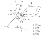
アンテナ付き樋22は、基本的構成要素として、雨水を流すための樋体1と、この樋体1の外面に重複されるアンテナ板5を備える。
The antenna-equipped
添付図面の実施形態では、アンテナ付き樋22は、更に、筒状をした樋体1を覆う外筒部23を備えることで二重筒構造となっており、また、長手方向の端部に、樋体1に連通接続する接続体24を備える。
In the embodiment of the attached drawings, the antenna-equipped
アンテナ板5は、金属板3にアンテナ部2を設けることで形成される。
The
アンテナ部2は、導電性の縦長矩形状の薄い金属板3(金属箔も含まれる)に樋体1の軸方向に沿って長く形成されたスロット28を設けたスロットアンテナにより構成される。
The
図7の実施形態では、金属板3に形成するアンテナ部2にはスロット28が上下方向に複数並べて設けられており、隣接するスロット28同士は細溝25で接続されている。各スロット28は三角形の頂点を互いに突き合わせたようなボウタイ形状に形成されている。
In the embodiment of FIG. 7, a plurality of
アンテナ部2は、第一の周波数帯(例えば473〜600MHz)の電波を受信する第一の受信部29と、第二の周波数帯(例えば600〜720MHz)の電波を受信する第二の受信部30を有している。
The
第一の受信部29は、スロット28及び当該スロット28の周縁部により構成される。第二の受信部30は、このスロット28に対し上下方向に隣接する鋼板部分により構成される。
The
第一の受信部29を構成するスロット28の上下方向の長さは、前記第一の周波数帯内の電波の電気的な半波長の長さと同じである。また、第二の受信部30の周方向の長さは、前記第二の周波数帯内の電波の電気的な半波長の長さと同じである。
The length of the
すなわち、第一の周波数帯内の中心周波数が536.5MHzであり、第一の周波数帯内の電波の電気的な半波長λ/2は約28cmであることから、各スロット28の上下方向の長さは約28cmとなっている。また、第二の周波数帯の中心周波数が660MHzであり、第二の周波数帯内の電波の電気的な半波長λ/2は約23cmであることから、第二の受信部30の周方向の長さは約23cmとなっている。
That is, the center frequency in the first frequency band is 536.5 MHz, and the electrical half wavelength λ / 2 of the radio wave in the first frequency band is about 28 cm. The length is about 28cm. Further, since the center frequency of the second frequency band is 660 MHz and the electric half wavelength λ / 2 of the radio wave in the second frequency band is about 23 cm, the circumferential direction of the second receiving
添付図面に示す実施形態では金属板3のスロット28の両側の三角形の頂点部分がそれぞれ給電部9となっている。
In the embodiment shown in the accompanying drawings, the apex portions of the triangles on both sides of the
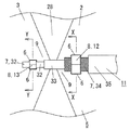
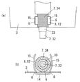
両給電部9にはそれぞれ図2に示すように、一対の差込孔が形成される。
As shown in FIG. 2, a pair of insertion holes is formed in each of the
給電部9には給電ケーブル11が接続される。
A
給電部9に接続する給電ケーブル11は同軸ケーブルにより構成され、図2に示すように、内側の芯線32の外側を芯線外皮部33で覆い、芯線外皮部33の外周を編線よりなる外側導電線34で覆い、更に外側導電線34を外側外皮部35で覆うことで構成される。
The
給電ケーブル11の端部は、外側外皮部35を除去して外側導電線34の端部が露出した部分が導電部7として形成され、更に、外側導電線34の端部より突出して芯線外皮部33が露出する部分が形成され、更に、芯線外皮部33の端部より芯線32が突出するする部分が他の導電部7として形成される。
The end portion of the
給電ケーブル11の芯線32、外側導電線34はそれぞれ一対の給電部9に止め金具8により接続される。
The
止め金具8は、弾性を有する黄銅板、ステンレス板等の金属材により形成され、図2、図10(c)、(d)に示すように中央片14の両端からそれぞれ中央片14に対して側片15を突出して略コ字状又は略C字状に形成される。
The
図10において、止め金具8の両側片15の突出基部間の距離をA、両側片15の突出先端間の距離をB、両側片15の突出方向の略中央部間の距離をC、止め金具8の巾をE、一対の差込孔間の距離をF、差込孔の長さをGとすると、A≒B≒F、G>E、C>Fとなっている。
In FIG. 10, the distance between the protruding bases of the both
止め金具8は、芯線止め金具13と、外側導線止め金具12の2種類があり、芯線止め金具13と芯線止め金具13が差し込まれる一対の差込み孔の各寸法関係、外側導線止め金具12と外側導線止め金具12が差し込まれる差込み孔の各寸法関係は、上記の寸法関係となっている。
There are two types of
給電ケーブル11の外側導電線34を一方の給電部9に外側導電線止め金具12で接続するには以下のようにして接続される。
In order to connect the outer conductive wire 34 of the
すなわち、外側導電線止め金具12の両側片15を一方の給電部9に設けた一対の差込み孔に差し込む。この場合、両側片15は弾性変形しながら差し込まれ、差し込んだ状態ではC>Fなので、外側導電線止め金具12が差込み孔から不用意に抜けないように保持される。
That is, the both
次に、図11のように、両側片15間に外側導電線34を嵌め込む。次に、図12(a)のように、かしめ装置16のかしめダイ17に設けた位置決め部18に中央片14を位置決めするようにセットし、図12(b)のようにかしめ装置16のかしめパンチ19を下降させ、両側片15を導電部7である外側導電線34の外周に沿って折り曲げて密着させる。これにより外側導電線34が両側片15により保持され、外側導電線34が金属板3に接触させられると共に外側導線止め金具12の中央片14が金属板3に接触させられ、電気的、機械的に接続される。
Next, as shown in FIG. 11, the outer conductive wire 34 is fitted between the both
なお、金属板3との電気的接続は、前述の例のように、金属板3に対して外側導電線34と中央片14が電気的に接触するものだけに限定されず、金属板3に外側導電線34のみが電気的に接触させられたり、あるいは、金属板に中央片14のみが電気的に接触させられたりしてもよい。
The electrical connection with the
また、図13(b)の寸法Jは、止め金具8の肉厚をD、金属板3の肉厚をH、外側導電線34の外径をKとすると、J=2D+H+Kとなり、きわめて短い寸法となり、外側外皮部35の外径とほぼ等しくなる。
The dimension J in FIG. 13B is an extremely short dimension with J = 2D + H + K, where D is the thickness of the
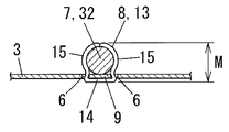
給電ケーブル11の芯線32を他方の給電部9に芯線止め金具13で接続するには、前述の外側導電線34接続と同様にして行われ、図14のように電気的、機械的に接続される。
The connection of the
図14における寸法Mは、芯線32の径が外側導電線34の径よりも短いので、図13(b)の寸法Jよりも短い寸法となる。
The dimension M in FIG. 14 is shorter than the dimension J in FIG. 13B because the diameter of the
このように、接続することで、接続に当ってネジ締めが不要になり生産性を向上することが可能となる。また、ネジ締めのためのビスやナットが不要となり、コストダウンが測れる。更に、ネジ締めでなく、かしめ固定することで、振動などによるネジの緩みながなく接続不良を抑制し、信頼性を向上させることができる。 Thus, by connecting, it is not necessary to tighten the screw in connection, and productivity can be improved. In addition, screws and nuts for screw tightening are unnecessary, and cost reduction can be measured. Furthermore, by fixing by caulking instead of screw tightening, there is no looseness of the screw due to vibration or the like, connection failure can be suppressed, and reliability can be improved.
また、接続部の寸法(図13(b)の寸法J、図14の寸法M)を短くでき、特に、寸法Jを外側外皮部35の外径とほぼ等しくできる。
Further, the dimension of the connecting portion (dimension J in FIG. 13B, dimension M in FIG. 14) can be shortened. In particular, the dimension J can be made substantially equal to the outer diameter of the
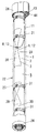
前記のように、給電ケーブル11を接続した状態のアンテナ板5は、水平断面C字状又は多角形状となるよう上下方向に一様に湾曲させて円筒状又は角筒状をした樋体1の外周面に巻いて重ね、接着や取付部材31を用いて取付けられる。
As described above, the
添付図面に示す実施形態は、図8に示すような取付部材31を用いて図5、図6に示すように取付けた例を示している。
The embodiment shown in the accompanying drawings shows an example in which the
前述のように給電部9に機械的、電気的に接続された給電ケーブル11は樋体1の外面に巻付けられたアンテナ板5の外面に樋体1の軸方向に沿って配置される。
As described above, the
軸方向に沿って配置するに当っては、スロット28を避けて配置される。
In arranging along the axial direction, the
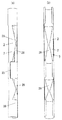
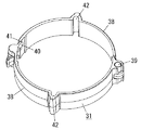
アンテナ板5を樋体1の外周面に取付けるための取付部材31は、非導電性の合成樹脂のような非導電性材料により形成されている。また、図8のように、取付部材31は、一対の半体38の一端部同士を軸受部39で回動自在に連結して構成され、一対の半体38の他端部の係止部40と被係止部41が係止自在となっている。
The
取付部材31は、給電ケーブル11のアンテナ板5に対する位置を保持するケーブル保持部42を備え、このケーブル保持部42に給電ケーブル11が保持される。
The
また、各取付部材31は、径外方向に突出する複数の突出部を有する。本実施形態の取付部材31は、軸受部39と、係止部40及び被係止部41と、ケーブル保持部42との計4箇所の突出部を有する。突出部は周方向に等間隔で配置されており、すなわち90°ごとに径外方向に突出する。
Each
外周にアンテナ板5を巻いた樋体1に外筒部23を被せることで、二重筒構造のアンテナ付き樋22が構成される。
A
外周にアンテナ板5を巻いた樋体1に外筒部23を被せると、取付部材31に突出部を設けているので、外筒部23の略中心に樋体1と樋体1に設けられたアンテナ板5の中心が配置されると共に、外筒部23の内周面に当接又は近接対向するようになる。
When the
給電ケーブル11の導電部7と給電部9との接続部は外筒部23により覆われ、また、給電ケーブル11は、樋体1の外周に巻いたアンテナ板5の外面と外筒部23との間に配置される。
A connecting portion between the
ここで、図13(b)の寸法Jが短い(外側外皮部35の外径とほぼ等しい)ので、アンテナ板5の外面と外筒部23との間の隙間寸法は、給電ケーブル11を配置するために必要な寸法を確保すれば、隙間内に導電部7と給電部9との接続部を十分納めることができる。
Here, since the dimension J of FIG. 13B is short (substantially equal to the outer diameter of the outer skin portion 35), the gap between the outer surface of the
これにより外筒部23の径を小さくすることが可能で、コストを低下でき、また、二重筒構造のアンテナ付き樋22の外観がよくなる。
Thereby, the diameter of the
なお、給電ケーブル11の芯線32は外側導電線34よりも径が小さいので、芯線32の接続に当っては、芯線止め金具13を用いることなく、ビスとナットを用いたネジ式で接続することも可能である。この場合、芯線32の接続部分の厚み寸法を短くすることが可能である。
Since the
また、導電部7と給電部9との接続部が外筒部23で覆われることで、接続部分を保護できて、接続部分に物や人が引っ掛かったりせず、また、外気、太陽光、雨水から接続部分を保護することが可能となり、信頼性が向上する。
Moreover, the connection part of the
二重筒構造のアンテナ付き樋22は、長手方向の端部に、接続体24が備えられ、上下の接続体24に樋体1と、外筒部23の上下方向の両端部が接続され、上下の接続体24は樋体1に連通する。
The double cylinder-structured
樋体1の軸方向に沿った給電ケーブル11は、接続体24に設けた引出部43に至り、給電ケーブル11の端部に設けた接続具44が引出部43を構成する孔に嵌め込んで取付けられる。
The
接続具44には、テレビ側ケーブル45の端部に設けた接続具が電気的に接続される。このテレビ側ケーブル45は、建物46の外壁47や軒天井48から建物内に導入され、既存の建物46内のテレビ側に接続される。
A connection tool provided at an end of the
図9は、アンテナ付き樋22が竪樋の一部として用いられた例を示している。図9において、符号49は軒樋、50は集水器、51はエルボ、52は呼び樋、53は一般の竪樋を示している。
FIG. 9 shows an example in which the
アンテナ付き樋22を竪樋の一部として用いる場合、アンテナ付き樋22の接続体24を一般の竪樋53やエルボ51に接続し、筒状をした樋体1内に雨水を流す。
When the antenna-equipped
接続の際、アンテナ付き樋22を軸芯を中心に回転して、アンテナ部2を最も強い受信方向に向ける。
At the time of connection, the antenna-equipped
なお、アンテナ部2を有する金属板3の表裏両面又は表面を電気的絶縁性を有する被覆フィルム4を積層してアンテナ板5を形成してもよい。
The
金属板3の表裏両面に被覆フィルム4を積層したアンテナ板5の場合は、図15のように、表裏両面又は片面の被覆フィルム4の給電部に対応する部位を除去して金属板3を露出させ、この露出面20に導電部7又は止め金具8の中央片14を電気的に接触させる。
In the case of the
金属板3の表面に被覆フィルム4を積層したアンテナ板5の場合は、給電部9の裏面が露出しているので、この露出面20に止め金具8の中央片14を電気的に接触させる。
In the case of the
このように、金属板3の表裏両面に被覆フィルム4を積層することで、金属板3を保護でき、金属板3の錆の発生を抑制でき、アンテナ性能が劣化するのを抑制できる。
Thus, by laminating the
前述の実施形態においては、外筒部23を設けた例で説明したが、外筒部23を設けないものであってもよい。
In the above-described embodiment, the example in which the
外筒部23を設けない場合、前述のように金属板3を被覆フィルム4で覆ったアンテナ板5においては、金属板3は雨水、外気、太陽光にさらされず、アンテナ部2の劣化を抑制できる。
When the
また、この場合も、導電部7と給電部9との接続部の厚さ方向の寸法を短くでき、樋体1の外面からの突出長さを短くでき、接続部分に人や物が引っ掛かるのが抑制される。
Also in this case, the dimension in the thickness direction of the connecting portion between the
1 樋体
2 アンテナ部
3 金属板
6 差込孔
7 導電部
8 止め金具
9 給電部
14 中央片
15 側片
DESCRIPTION OF
Claims (4)
前記給電部に一対の差込孔を形成し、この一対の差込孔に止め金具の両側片を差し込んで前記両側片で給電ケーブルの導電部を保持させ、前記導電部を前記金属板に接触させるか、又は、前記止め金具の中央片を前記金属板に接触させることを特徴とするアンテナ付き樋。 A housing for flowing rainwater, a metal plate having an antenna portion overlapped on the surface of the housing, and a power feeding portion provided in the antenna portion,
A pair of insertion holes are formed in the power feeding portion, and both side pieces of the metal fitting are inserted into the pair of insertion holes to hold the conductive portion of the power feeding cable with the both side pieces, and the conductive portion is in contact with the metal plate. Or a hook with an antenna, wherein the central piece of the stopper is brought into contact with the metal plate.
4. The scissor with an antenna according to claim 1, wherein the both side pieces are bent and adhered along the outer periphery of the conductive portion. 5.
Priority Applications (1)
| Application Number | Priority Date | Filing Date | Title |
|---|---|---|---|
| JP2011060862A JP5608117B2 (en) | 2011-03-18 | 2011-03-18 | 樋 with antenna |
Applications Claiming Priority (1)
| Application Number | Priority Date | Filing Date | Title |
|---|---|---|---|
| JP2011060862A JP5608117B2 (en) | 2011-03-18 | 2011-03-18 | 樋 with antenna |
Publications (2)
| Publication Number | Publication Date |
|---|---|
| JP2012199635A true JP2012199635A (en) | 2012-10-18 |
| JP5608117B2 JP5608117B2 (en) | 2014-10-15 |
Family
ID=47181463
Family Applications (1)
| Application Number | Title | Priority Date | Filing Date |
|---|---|---|---|
| JP2011060862A Expired - Fee Related JP5608117B2 (en) | 2011-03-18 | 2011-03-18 | 樋 with antenna |
Country Status (1)
| Country | Link |
|---|---|
| JP (1) | JP5608117B2 (en) |
Citations (6)
| Publication number | Priority date | Publication date | Assignee | Title |
|---|---|---|---|---|
| JPH03195201A (en) * | 1989-12-25 | 1991-08-26 | Matsushita Electric Works Ltd | Gutter antenna |
| JPH056918U (en) * | 1991-06-28 | 1993-01-29 | セントラル硝子株式会社 | Glass antenna connection structure |
| JPH0653721A (en) * | 1992-07-31 | 1994-02-25 | Central Glass Co Ltd | Connection structure for glass antenna |
| JPH09148839A (en) * | 1995-11-20 | 1997-06-06 | Sansei Denki Kk | Antenna for portable radio telephone set and constituting method therefor |
| JP2004031068A (en) * | 2002-06-25 | 2004-01-29 | Harada Ind Co Ltd | Connection terminal structure for film antenna |
| JP2010226550A (en) * | 2009-03-25 | 2010-10-07 | Mitsumi Electric Co Ltd | Antenna device |
-
2011
- 2011-03-18 JP JP2011060862A patent/JP5608117B2/en not_active Expired - Fee Related
Patent Citations (6)
| Publication number | Priority date | Publication date | Assignee | Title |
|---|---|---|---|---|
| JPH03195201A (en) * | 1989-12-25 | 1991-08-26 | Matsushita Electric Works Ltd | Gutter antenna |
| JPH056918U (en) * | 1991-06-28 | 1993-01-29 | セントラル硝子株式会社 | Glass antenna connection structure |
| JPH0653721A (en) * | 1992-07-31 | 1994-02-25 | Central Glass Co Ltd | Connection structure for glass antenna |
| JPH09148839A (en) * | 1995-11-20 | 1997-06-06 | Sansei Denki Kk | Antenna for portable radio telephone set and constituting method therefor |
| JP2004031068A (en) * | 2002-06-25 | 2004-01-29 | Harada Ind Co Ltd | Connection terminal structure for film antenna |
| JP2010226550A (en) * | 2009-03-25 | 2010-10-07 | Mitsumi Electric Co Ltd | Antenna device |
Also Published As
| Publication number | Publication date |
|---|---|
| JP5608117B2 (en) | 2014-10-15 |
Similar Documents
| Publication | Publication Date | Title |
|---|---|---|
| US6669511B1 (en) | Structure for connecting shielded cable to shield connector | |
| US8410378B1 (en) | Grounding fitting | |
| US7901256B1 (en) | Bonding and grounding clamp/connector for electrode conductors | |
| CN103855660A (en) | Electrical junction box | |
| US9106007B2 (en) | Electrical junction box | |
| US7446725B2 (en) | Antenna structure assembly | |
| CN109780301B (en) | Coil and expansion valve for valve | |
| JP5608117B2 (en) | 樋 with antenna | |
| JP5593909B2 (en) | Housing grounding mechanism | |
| JP6506923B2 (en) | Antenna device | |
| JP2012195862A (en) | Gutter with antenna | |
| JP2012195859A (en) | Gutter with antenna | |
| JP5699281B2 (en) | A member wrapped with a metal plate | |
| JP4540325B2 (en) | TV receiving antenna device | |
| JP2012195861A (en) | Gutter with antenna and manufacturing method of antenna plate used in the gutter with the antenna | |
| WO2006103820A1 (en) | On-vehicle antenna | |
| JP5524916B2 (en) | Mounting structure of antenna to rain gutter | |
| JP5608134B2 (en) | Antenna device | |
| JP3656720B2 (en) | Antenna unit for wireless remote control system of switchgear | |
| US20240022009A1 (en) | Electrical terminal and assembly | |
| JP4166418B2 (en) | Insulation cover spacer | |
| JP2000113940A (en) | Connection structure of conductive tube | |
| JP2007067970A (en) | Antenna and antenna cable attaching structure | |
| JP4339105B2 (en) | Loop antenna | |
| JP2012199001A (en) | Connection structure of conductive wire to metal plate covered with insulation material |
Legal Events
| Date | Code | Title | Description |
|---|---|---|---|
| A621 | Written request for application examination |
Free format text: JAPANESE INTERMEDIATE CODE: A621 Effective date: 20130711 |
|
| A977 | Report on retrieval |
Free format text: JAPANESE INTERMEDIATE CODE: A971007 Effective date: 20140109 |
|
| A131 | Notification of reasons for refusal |
Free format text: JAPANESE INTERMEDIATE CODE: A131 Effective date: 20140128 |
|
| A521 | Written amendment |
Free format text: JAPANESE INTERMEDIATE CODE: A523 Effective date: 20140331 |
|
| TRDD | Decision of grant or rejection written | ||
| A01 | Written decision to grant a patent or to grant a registration (utility model) |
Free format text: JAPANESE INTERMEDIATE CODE: A01 Effective date: 20140805 |
|
| A61 | First payment of annual fees (during grant procedure) |
Free format text: JAPANESE INTERMEDIATE CODE: A61 Effective date: 20140829 |
|
| LAPS | Cancellation because of no payment of annual fees |