JP2012199802A - Imaging apparatus, control method of the same, and program - Google Patents
Imaging apparatus, control method of the same, and program Download PDFInfo
- Publication number
- JP2012199802A JP2012199802A JP2011062925A JP2011062925A JP2012199802A JP 2012199802 A JP2012199802 A JP 2012199802A JP 2011062925 A JP2011062925 A JP 2011062925A JP 2011062925 A JP2011062925 A JP 2011062925A JP 2012199802 A JP2012199802 A JP 2012199802A
- Authority
- JP
- Japan
- Prior art keywords
- frequency
- vibration
- image
- distortion
- distortion amount
- Prior art date
- Legal status (The legal status is an assumption and is not a legal conclusion. Google has not performed a legal analysis and makes no representation as to the accuracy of the status listed.)
- Granted
Links
Images








Classifications
-
- H—ELECTRICITY
- H04—ELECTRIC COMMUNICATION TECHNIQUE
- H04N—PICTORIAL COMMUNICATION, e.g. TELEVISION
- H04N25/00—Circuitry of solid-state image sensors [SSIS]; Control thereof
- H04N25/50—Control of the SSIS exposure
- H04N25/53—Control of the integration time
- H04N25/531—Control of the integration time by controlling rolling shutters in CMOS SSIS
-
- H—ELECTRICITY
- H04—ELECTRIC COMMUNICATION TECHNIQUE
- H04N—PICTORIAL COMMUNICATION, e.g. TELEVISION
- H04N23/00—Cameras or camera modules comprising electronic image sensors; Control thereof
- H04N23/60—Control of cameras or camera modules
- H04N23/68—Control of cameras or camera modules for stable pick-up of the scene, e.g. compensating for camera body vibrations
- H04N23/681—Motion detection
- H04N23/6811—Motion detection based on the image signal
Landscapes
- Engineering & Computer Science (AREA)
- Multimedia (AREA)
- Signal Processing (AREA)
- Studio Devices (AREA)
- Transforming Light Signals Into Electric Signals (AREA)
Abstract
【課題】ローリングシャッタ問題による歪みを補正する場合の補正残り、あるいは過補正を低減する。
【解決手段】ローリングシャッタ方式で駆動する撮像素子を用いて画像を撮像する場合に、当該撮像素子の露光期間における撮像装置の振動を検出し、検出された振動の時間特性を取得する。振動の時間特性について、振動に起因して画像に生じる被写体像の歪み量の周波数分布を解析し、当該周波数分布から歪み量が極大となる周波数を、歪み量の中心周波数として決定する。そして少なくとも中心周波数について、振動の時間特性を取得した際に生じた位相ズレがなくなるように、振動の時間特性を補償し、補償後の振動の時間特性から算出された補正量を用いて、撮像素子のラインごとに振動に起因して生じた被写体像の歪みを補正する。
【選択図】図2Remaining correction or overcorrection when correcting distortion due to a rolling shutter problem is reduced.
When an image is picked up using an image pickup device driven by a rolling shutter system, vibration of the image pickup apparatus during an exposure period of the image pickup device is detected, and a time characteristic of the detected vibration is acquired. Regarding the time characteristics of vibration, the frequency distribution of the distortion amount of the subject image generated in the image due to the vibration is analyzed, and the frequency at which the distortion amount is maximized is determined from the frequency distribution as the center frequency of the distortion amount. Then, at least for the center frequency, the vibration time characteristic is compensated so as to eliminate the phase shift that occurs when the vibration time characteristic is acquired, and imaging is performed using the correction amount calculated from the compensated vibration time characteristic. The distortion of the subject image caused by vibration is corrected for each element line.
[Selection] Figure 2
Description
本発明は、撮像された画像に含まれる、手ぶれによる画像の歪みを補正する技術に関する。 The present invention relates to a technique for correcting image distortion caused by camera shake included in a captured image.
近年、デジタルビデオカメラのような撮像装置は、撮像素子として、CCDより消費電力が低いCMOSセンサが用いられるようになってきている。CCDとCMOSセンサの違いは、消費電力だけでなく、その撮影時の露光方式についても両者は異なる。 In recent years, an imaging apparatus such as a digital video camera has come to use a CMOS sensor whose power consumption is lower than that of a CCD as an imaging element. The difference between the CCD and the CMOS sensor is not only the power consumption but also the exposure method at the time of photographing.
CCDでは1つの撮像画像を撮像する際に、撮像素子の全ての画素の露光タイミング及び露光期間が同一であるのに対し、CMOSセンサでは撮像素子を構成するラインごとにシャッタの開閉タイミングが異なるため露光期間に差が生じる。CMOSセンサのような駆動方式は、ローリングシャッタ方式と呼ばれる。 In the CCD, when one captured image is captured, the exposure timing and the exposure period of all the pixels of the image sensor are the same, whereas in the CMOS sensor, the shutter opening / closing timing differs for each line constituting the image sensor. Differences occur in the exposure period. A driving method such as a CMOS sensor is called a rolling shutter method.
このようなローリングシャッタ方式の撮像素子で撮影を行った場合、例えば露光中の被写体の移動、あるいは露光中の撮像装置を把持する撮影者の手ぶれにより、撮像素子のラインごとに被写体像が移動するため、撮像画像において歪みが生じることがあった。当該歪みが発生する現象は、「ローリングシャッタ問題」や「フォーカルプレーン現象」と呼ばれる。特にローリングシャッタ問題による歪みは、メカシャッタを用いる静止画撮影よりも、メカシャッタを用いない動画撮影において、より顕著に現れうる。 When shooting is performed with such a rolling shutter type imaging device, the subject image moves for each line of the imaging device due to, for example, movement of the subject during exposure or camera shake of the photographer holding the imaging device during exposure. Therefore, distortion may occur in the captured image. The phenomenon in which the distortion occurs is called “rolling shutter problem” or “focal plane phenomenon”. In particular, distortion due to the rolling shutter problem can be more noticeable in moving image shooting that does not use a mechanical shutter than in still image shooting that uses a mechanical shutter.
上述したようなローリングシャッタ問題による歪みのうち、撮影者の手ぶれにより生じた歪みを補正する技術が特許文献1に開示されている。特許文献1では、撮像装置に設けられた角速度センサにより検出した手ぶれ速度を積分することにより手ぶれの時間特性を取得し、撮像素子のラインごとの撮影時の撮像装置の位置変化に応じて歪みを補正することが開示されている。
Among the distortions due to the rolling shutter problem as described above, a technique for correcting distortion caused by camera shake of a photographer is disclosed in
しかしながら、角速度センサのサンプリング周波数が数kHz〜数十kHzであるのに対し、手ぶれの周波数は0Hz〜15Hz程度であり、両者の周波数はオーダーが著しく異なる。このような角速度センサの出力信号から手ぶれの時間特性を取得するために、特許文献1に示されるFIR(有限インパルス応答)フィルタを用いて信号処理する場合、多くのタップ数が必要となるため、回路規模を増大させてしまうことになる。
However, while the sampling frequency of the angular velocity sensor is several kHz to several tens of kHz, the frequency of camera shake is about 0 Hz to 15 Hz, and the order of both frequencies is significantly different. In order to acquire the time characteristic of camera shake from the output signal of such an angular velocity sensor, when signal processing is performed using the FIR (finite impulse response) filter disclosed in
回路規模の増大を回避するためには、FIRフィルタではなくIIR(無限インパルス応答)フィルタを用いることが考えられるが、IIRフィルタは直線位相ではないため、周波数帯ごとに異なる位相遅れあるいは位相進みを生じる。即ち、このようにIIRフィルタを用いて得られた手ぶれの時間特性にはIIRフィルタの位相特性による位相ズレが生じているため、手ぶれの周波数によってはローリングシャッタ問題による歪みを補正するための補正量が正しく算出されないことがある。つまり、IIRフィルタを用いて得られた手ぶれの時間特性から算出した補正量を用いて、ローリングシャッタ問題による歪みを補正した場合、画像に補整残り、あるいは過補正といった現象が生じることになる。 In order to avoid an increase in circuit scale, it is conceivable to use an IIR (infinite impulse response) filter instead of an FIR filter. However, since an IIR filter is not a linear phase, a phase lag or phase lead that differs for each frequency band is used. Arise. That is, since the phase shift due to the phase characteristic of the IIR filter occurs in the time characteristic of the camera shake obtained by using the IIR filter in this way, a correction amount for correcting distortion due to the rolling shutter problem depending on the frequency of the camera shake. May not be calculated correctly. In other words, when the distortion due to the rolling shutter problem is corrected using the correction amount calculated from the time characteristic of camera shake obtained using the IIR filter, a phenomenon such as residual correction or overcorrection occurs in the image.
本発明は、上述の問題点に鑑みてなされたものであり、ローリングシャッタ問題による歪みを補正する場合の補正残り、あるいは過補正を低減することを目的とする。 The present invention has been made in view of the above-described problems, and an object thereof is to reduce residual correction or overcorrection when correcting distortion due to a rolling shutter problem.
前述の目的を達成するために、本発明の撮像装置の一態様は、以下の構成を備える。
ローリングシャッタ方式で駆動する撮像素子を備える撮像装置であって、撮像素子を用いて画像を撮像する場合に、当該撮像素子の露光期間における撮像装置の振動を検出する検出手段と、検出手段により検出された振動の時間特性を取得する取得手段と、振動の時間特性について、振動に起因して画像に生じる被写体像の歪み量の周波数分布を解析する解析手段と、歪み量の周波数分布から、当該歪み量が極大となる周波数を歪み量の中心周波数として決定する決定手段と、少なくとも中心周波数について、前記取得手段により生じた位相ズレがなくなるように、振動の時間特性を補償する補償手段と、補償手段により補償された振動から算出された補正量を用いて、撮像素子のラインごとに振動に起因して生じた被写体像の歪みを補正する補正手段と、を備えることを特徴とする。
In order to achieve the above object, one aspect of an imaging apparatus of the present invention has the following configuration.
An image pickup apparatus including an image pickup element driven by a rolling shutter method, and when an image is picked up using the image pickup element, detection means for detecting vibration of the image pickup apparatus during an exposure period of the image pickup element, and detection by the detection means From the acquisition means for acquiring the time characteristic of the vibration, the analysis means for analyzing the frequency distribution of the distortion amount of the subject image generated in the image due to the vibration, and the frequency distribution of the distortion amount A determination unit that determines a frequency at which the distortion amount is maximum as a center frequency of the distortion amount, a compensation unit that compensates a time characteristic of vibration so as to eliminate a phase shift caused by the acquisition unit at least for the center frequency, and a compensation Using the correction amount calculated from the vibration compensated by the means, the distortion of the subject image caused by the vibration is corrected for each line of the image sensor. Characterized in that it comprises a correcting means.
また、本発明の撮像装置の別の態様は、以下の構成を備える。
ローリングシャッタ方式で駆動する撮像素子を備える撮像装置であって、撮像素子を用いて画像を撮像する場合に、当該撮像素子の露光期間における撮像装置の振動を検出する検出手段と、検出手段により検出された振動の時間特性を取得する取得手段と、画像を撮像時の撮像装置のパラメータに基づいて、振動に起因して画像に生じる被写体像の歪み量の中心周波数が存在すると推定される周波数帯を含む複数の周波数を検波周波数として選択する第1の選択手段と、振動の時間特性について、振動のうちの検波周波数に起因して画像に生じる被写体像の歪み量の周波数分布を解析する解析手段と、歪み量の周波数分布から、当該歪み量が極大となる周波数を歪み量の中心周波数として決定する決定手段と、少なくとも中心周波数について、前記取得手段により生じた位相ズレがなくなるように、振動の時間特性を補償する補償手段と、補償手段により補償された振動から算出された補正量を用いて、撮像素子のラインごとに振動に起因して生じた被写体像の歪みを補正する補正手段と、を備えることを特徴とする。
Another aspect of the imaging apparatus of the present invention has the following configuration.
An image pickup apparatus including an image pickup element driven by a rolling shutter method, and when an image is picked up using the image pickup element, detection means for detecting vibration of the image pickup apparatus during an exposure period of the image pickup element, and detection by the detection means The frequency band in which the center frequency of the distortion amount of the subject image generated in the image due to the vibration exists based on the acquisition means for acquiring the time characteristic of the vibration and the imaging device parameters at the time of capturing the image A first selection unit that selects a plurality of frequencies including a detection frequency, and an analysis unit that analyzes a frequency distribution of a distortion amount of a subject image generated in the image due to the detection frequency of the vibration with respect to time characteristics of vibration Determining means for determining the frequency at which the distortion amount is maximum from the frequency distribution of the distortion amount as the center frequency of the distortion amount, and at least the center frequency The compensation means for compensating the time characteristic of vibration so as to eliminate the phase shift caused by the acquisition means, and the correction amount calculated from the vibration compensated by the compensation means Correction means for correcting the distortion of the subject image generated in this way.
このような構成により本発明によれば、ローリングシャッタ問題による歪みを補正する場合の補正残り、あるいは過補正を低減することが可能となる。 With such a configuration, according to the present invention, it is possible to reduce the remaining correction or overcorrection when correcting distortion due to the rolling shutter problem.
(実施形態1)
以下、本発明の好適な一実施形態について、図面を参照して詳細に説明する。なお、以下に説明する一実施形態は、撮像装置の一例としての、ローリングシャッタ問題による歪みのうち、手ぶれに起因して生じる歪みを補正可能なデジタルビデオカメラに、本発明を適用した例を説明する。しかし、本発明は、ローリングシャッタ問題による歪みのうち、手ぶれに起因して生じる歪みを補正することが可能な任意の機器に適用可能である。また、本明細書において、「ローリングシャッタ問題により生じる歪み」のうち、手ぶれに起因して生じる歪みを「ローリング歪み」として記載し、以下に説明するものとする。
(Embodiment 1)
Hereinafter, a preferred embodiment of the present invention will be described in detail with reference to the drawings. Note that in the embodiment described below, an example in which the present invention is applied to a digital video camera that can correct distortion caused by camera shake among distortions due to a rolling shutter problem as an example of an imaging apparatus will be described. To do. However, the present invention can be applied to any device capable of correcting distortion caused by camera shake among distortions due to the rolling shutter problem. Further, in this specification, among the “distortions caused by the rolling shutter problem”, distortions caused by camera shake are described as “rolling distortion” and will be described below.
(デジタルビデオカメラ100の機能構成)
図1は、本発明の実施形態に係るデジタルビデオカメラ100の機能構成を示すブロック図である。
(Functional configuration of digital video camera 100)
FIG. 1 is a block diagram showing a functional configuration of a
制御部101は、例えばCPUであり、デジタルビデオカメラ100が備える各ブロックの動作を制御する。具体的には制御部101は、例えばROM102に記憶されている撮影処理等の処理プログラムを読み出して、不図示の揮発性メモリに展開して実行することにより、デジタルビデオカメラ100が備える各ブロックの動作を制御する。ROM102は、書き換え可能な不揮発性メモリであり、上述した処理プログラムに加え、各ブロックの動作において必要なパラメータ等が記憶される。
The
なお、本実施形態ではハードウェアとしてデジタルビデオカメラ100が備える各ブロックにおいて各処理が実現されるものとして説明するが、本発明の実施はこれに限らず、各ブロックの処理は当該各ブロックと同様の処理を行うプログラムで実現されてもよい。
In the present embodiment, description will be made assuming that each process is realized in each block of the
撮像部103は、例えばCMOSセンサ等のローリングシャッタ方式の撮像素子を備えるブロックである。撮像部103は、不図示の光学系により撮像素子に結像された光学像を光電変換して得られたアナログ画像信号に対してA/D変換処理を適用し、デジタル画像信号(画像データ)を出力する。撮像部103より出力された画像データは、例えば画像メモリ104に一時的に格納される。
The
画像処理部107は、撮像部103により撮像されて画像メモリ104に格納された画像データに対して、ゲイン調整、ホワイトバランス調整等の画像処理を適用するブロックである。また画像処理部107は、後述する歪み補正量算出部106により算出された歪み補正量を用いて、画像メモリ104に格納された画像データに生じている、ローリング歪みをラインごとに補正する。
The
デジタルビデオカメラ100を用いて動画撮影を行う場合、画像処理部107において各種画像処理あるいはローリング歪み補正処理が実行された画像データは、所定の符号化方式に従って画像処理部107において符号化される。そして符号化されて得られた動画データは、記録媒体108に伝送されて記録される。
When moving image shooting is performed using the
ブレ検出部105は、例えば角速度センサであって、デジタルビデオカメラ100に加わったぶれ(手ぶれ)により生じる角速度を検出するセンサである。ブレ検出部105は、検出したデジタルビデオカメラ100の3軸の角速度を、例えば歪み補正量算出部106に出力する。
The
歪み補正量算出部106は、手ぶれにより画像データ内の像に生じたローリング歪みを補正する補正量を算出するブロックであり、算出した補正量の情報を画像処理部107に出力する。
The distortion correction
(歪み補正量算出部106の内部構成)
ここで、歪み補正量算出部106の内部構成、及び歪み補正量算出部106内で行われる処理について、図を用いて以下に詳細に説明する。
(Internal configuration of distortion correction amount calculation unit 106)
Here, the internal configuration of the distortion correction
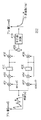
図2(a)は、本実施形態に係る歪み補正量算出部106の内部構成を示した図である。歪み補正量算出部106には、ブレ検出部105により検出された、1フレームの画像の撮像中に生じた角速度変化の情報が入力される。
FIG. 2A is a diagram illustrating an internal configuration of the distortion correction
ブレ量算出部201は、入力された1フレームの画像の撮像中に生じた角速度変化の情報から、当該角速度変化による撮像素子上の画素を単位とした像のブレ量の時間特性を取得する。
The blur
ブレ量算出部201は、図3に示すような構成となっており、まず入力された角速度変化の情報はIIRフィルタ301で手ぶれの周波数に合わせて信号処理される。さらにブレ量算出部201により出力された角速度変化情報は、積分器302において積分処理がなされることにより、手ぶれの角変位情報θとして出力される。なお、手ぶれの角変位情報θは、例えばローリング歪みが生じうる、撮像素子の撮像面に対するピッチ方向及びヨー方向の角度について出力される。
The shake
ブレ量変換部303は、積分器302から入力された角変位情報θを、当該角変異により生じる、撮像素子上の画素を単位とした像のブレ量に変換する。具体的にはブレ量変換部303は、以下の式を用いて角変位情報θから、撮像素子上の像のブレ量に変換する。
fL・tanθ/p
ここで、fLは焦点距離、pは撮像素子上の画素ピッチである。
The blur
f L · tan θ / p
Here, f L is a focal length, and p is a pixel pitch on the image sensor.
このように算出されたブレ量の時間特性は、位相補償部205及びブレ量解析部202に出力される。
The time characteristic of the shake amount calculated in this way is output to the
なお、ブレ量算出部201では、IIRフィルタ301による手ぶれの周波数に応じた位相ズレ、及び積分器302の積分演算によるπ/2の位相遅れが生じることになる。このうち後者の積分演算による位相遅れについては手ぶれの周波数によらず固定の位相ズレであるため、π/2位相進めるように処理することにより影響をなくすことができる。本実施形態では、手ぶれの周波数に応じた位相ズレを低減するために、1フレームの撮像中に生じた手ぶれの周波数分布から手ぶれの中心周波数を特定する。そして、後述のブレ量解析部202、中心周波数決定部203、及び位相補償制御部204の処理において、少なくとも当該中心周波数について位相ズレが積分演算によるπ/2のみとなるように位相補償パラメータを算出し、位相補償部205に出力する。
In the shake
ブレ量解析部202は、入力された手ぶれの時間特性に対して離散フーリエ変換を実行することにより、手ぶれの周波数分布を解析する。ブレ量解析部202における離散フーリエ変換は、図4に示すような回路構成によりハードウェアにおいて実行可能である。
The shake
入力された手ぶれの時間特性は、乗算器401及び乗算器402のそれぞれにおいて、所望の周波数の正弦波または余弦波が乗算され、加算器403または加算器404に入力される。シフトレジスタ405は、加算器403からの出力を遅延させ、乗算器407及び加算器403に出力する。同様にシフトレジスタ406は、加算器404からの出力を遅延させ、乗算器408及び加算器404に出力する。乗算器407及び乗算器408は、それぞれシフトレジスタ405及びシフトレジスタ406の出力を2乗する。そして乗算された結果は加算器409で足し合わせられた後、平方根演算器410で平方根を算出する。このようにすることで、離散フーリエ変換をハードウェアとして実行できる。
The time characteristics of the input camera shake are multiplied by a sine wave or cosine wave of a desired frequency in each of the
ブレ量解析部202で解析されたブレ量の周波数分布は、中心周波数決定部203に出力される。一般にはブレ量の周波数分布は図4に示すように、0〜15Hzに分布し、低周波であるほどブレ量、即ち手ぶれの振幅(最大ブレ量)が大きくなる傾向を示す。
The frequency distribution of the blur amount analyzed by the blur
中心周波数決定部203は、入力されたブレ量の周波数分布から、1フレームの撮像中に生じた手ぶれの中心周波数を決定する。
The center
ブレ量解析部202で解析されたブレ量の周波数分布から、手ぶれの時間特性のうち、単一周波数fの振動は、当該周波数における最大ブレ量である振幅A(f)を用いて、
A(f)・sin(ωt) (ω=2πf)
と表すことができる。即ち、周波数ごとの振動の速度は、手ぶれの時間特性を微分して
A(f)ω・cos(ωt)
と表すことができる。
From the frequency distribution of the shake amount analyzed by the shake
A (f) · sin (ωt) (ω = 2πf)
It can be expressed as. That is, the vibration speed for each frequency is obtained by differentiating the time characteristic of camera shake by A (f) ω · cos (ωt)
It can be expressed as.
例えば、撮像素子の連続するライン間の露光開始の時刻の差がΔtである場合、前のラインの撮像が開始されてから次のラインの撮像が開始されるまでの期間Δtでの像の変位量は、図5(a)のようなΔtの中央の時刻t0の速度を平均速度とみなし、
A(f)ω・cos(ωt0)・Δt
と表すことができる。当該式から、既にブレ量解析部202より得られているA(f)(図5(b))を分離し、ωt0が一定として近似すると、残りの項は
ω・cos(ωt0)・Δt
⇒2π・cos(ωt0)・Δt×f=c×f (c=const.)
と変形でき、図5(c)のような周波数に対する一次関数で表すことができる。
For example, when the difference in exposure start time between successive lines of the image sensor is Δt, the image displacement in the period Δt from the start of imaging of the previous line to the start of imaging of the next line As for the quantity, the speed at the time t 0 at the center of Δt as shown in FIG.
A (f) ω · cos (ωt 0 ) · Δt
It can be expressed as. If A (f) (FIG. 5 (b)) already obtained from the blur
⇒ 2π · cos (ωt 0 ) · Δt × f = c × f (c = const.)
And can be expressed by a linear function with respect to the frequency as shown in FIG.
即ち、中心周波数決定部203では、入力された図5(b)のようなブレ量の周波数分布に対して、図5(c)のような一次関数を乗じることにより、図5(d)のような撮像画像における歪み量の周波数分布を得ることができる。
That is, the center
本実施形態では、撮像画像における歪み量の周波数分布において歪み量が最大となる周波数faを中心周波数として決定する。そして、当該中心周波数においてIIRフィルタ301による位相遅れがπ/2となるように後述する位相補償制御部204に位相補償パラメータを設定させる。このようにすることで、歪み量が最も大きい、即ち位相ズレが生じた場合に像の補整残りまたは過補正による歪みが目立ちやすい周波数(中心周波数)において歪みをなくすようにできる。
In the present embodiment, the distortion amount is determined as the center frequency f a which maximizes the frequency distribution of the amount of distortion in the captured image. Then, a phase compensation parameter is set in the
位相補償制御部204は、位相補償部205での手ぶれの時間特性の位相補償処理において、中心周波数決定部203で決定した中心周波数近傍の位相遅れがπ/2となるような位相補償パラメータを算出して、位相補償部205に出力する。なお、位相補償パラメータは、中心周波数近傍の周波数帯において、位相補償後のブレ量の位相が目標位相である−π/2となるように、公知の方法で決定される。
The phase
位相補償部205は、位相補償フィルタであり、例えば当該位相補償フィルタの位相特性は図7(a)のようになる。位相補償部205は、入力された手ぶれの時間特性を、中心周波数決定部203で決定された中心周波数でIIRフィルタ301により生じた位相ズレを補償し、当該周波数での位相遅れが積分器302により生じたπ/2となるように位相補償を行う。
The
位相補償部205の内部構成は、例えば図6のようになる。加算器601は、入力された手ぶれの時間特性(ブレ量)と、後述する増幅器603の出力とを足し合わせ、位相補償後のブレ量を撮像画像歪み量算出部206に出力する。またシフトレジスタ602は、入力された位相補償後のブレ量を遅延させ、増幅器603に出力する。増幅器603は、シフトレジスタ602からの出力に対して、位相補償制御部204より入力された位相補償パラメータであるフィルタ係数Kを乗算して加算器601に出力する。
The internal configuration of the
このような構成により、位相補償制御部204で適切に設定された位相補償パラメータを用いて、位相補償部205の出力であるブレ量の位相特性を、図7(b)のように中心周波数において−π/2とすることができる。
With such a configuration, using the phase compensation parameter appropriately set by the phase
撮像画像歪み量算出部206は、入力された位相補償後の手ぶれの時間特性を用いて、ブレ量算出部201における位相ズレが補償された、撮像素子のラインごとの撮像画像の歪み量を算出する。撮像素子のライン間の撮像画像の歪み量は、例えばNライン目とN+1ライン目の間に生じる歪み量を例にとると、図8に示すように露光開始時刻におけるブレ量の差から算出することができる。
The captured image distortion
このように算出された歪み量をなくすように決定された補正量を用いて、画像処理部107は、撮像素子のラインごとに、ローリングシャッタ問題による撮像画像の歪みを補正することができる。
Using the correction amount determined so as to eliminate the distortion amount calculated in this way, the
(まとめ)
以上説明したように、本実施形態の撮像装置は、ローリングシャッタ問題による歪みを補正する場合の補正残り、あるいは過補正を低減することができる。具体的には撮像装置は、ローリングシャッタ方式で駆動する撮像素子を用いて画像を撮像する場合に、当該撮像素子の露光期間における撮像装置の振動を検出し、検出された振動の時間特性を取得する。振動の時間特性について、振動に起因して画像に生じる被写体像の歪み量の周波数分布を解析し、当該周波数分布から歪み量が極大となる周波数を、歪み量の中心周波数として決定する。そして少なくとも中心周波数について、振動の時間特性を取得した際に生じた位相ズレがなくなるように、振動の時間特性を補償し、補償後の振動の時間特性から算出された補正量を用いて、撮像素子のラインごとに振動に起因して生じた被写体像の歪みを補正する。
(Summary)
As described above, the imaging apparatus according to the present embodiment can reduce the remaining correction or overcorrection when correcting distortion due to the rolling shutter problem. Specifically, when an imaging device captures an image using an imaging device driven by a rolling shutter method, the imaging device detects vibration of the imaging device during the exposure period of the imaging device, and obtains time characteristics of the detected vibration. To do. Regarding the time characteristics of vibration, the frequency distribution of the distortion amount of the subject image generated in the image due to the vibration is analyzed, and the frequency at which the distortion amount is maximized is determined from the frequency distribution as the center frequency of the distortion amount. Then, at least for the center frequency, the vibration time characteristic is compensated so as to eliminate the phase shift that occurs when the vibration time characteristic is acquired, and imaging is performed using the correction amount calculated from the compensated vibration time characteristic. The distortion of the subject image caused by vibration is corrected for each element line.
このようにすることで、少なくとも、撮像画像における歪み量が最も大きく、補整残りあるいは過補正による歪みが目立ちやすい中心周波数について、IIRフィルタを用いたことによる位相ズレを補償することができる。このため、ローリングシャッタ問題による歪みを補正した場合に、撮像画像全体において歪みを目立たなくすることができる。さらに、1フレームの画像を撮像中の手ぶれの時間特性に応じて動的に中心周波数を決定するため、適切にローリングシャッタ問題による歪みを補正することができる。 By doing so, at least the center frequency at which the distortion amount in the captured image is the largest and the correction residual or distortion due to overcorrection is conspicuous can be compensated for the phase shift caused by using the IIR filter. For this reason, when the distortion due to the rolling shutter problem is corrected, the distortion can be made inconspicuous in the entire captured image. Furthermore, since the center frequency is dynamically determined in accordance with the time characteristics of camera shake during imaging of one frame image, distortion due to the rolling shutter problem can be corrected appropriately.
(実施形態2)
上述した実施形態1では、手ぶれの時間特性の全ての周波数についてブレ量の周波数分布を解析して中心周波数を決定する方法について説明した。本実施形態2では、限られた周波数についてのブレ量の周波数分布を解析することにより中心周波数を決定する方法について説明する。
(Embodiment 2)
In the first embodiment described above, the method for determining the center frequency by analyzing the frequency distribution of the blur amount for all the frequencies of the time characteristic of camera shake has been described. In the second embodiment, a method for determining the center frequency by analyzing the frequency distribution of the blur amount for a limited frequency will be described.
(歪み補正量算出部106の内部構成)
図2(b)は、本実施形態に係る歪み補正量算出部106の内部構成を示した図である。なお、本実施形態の歪み補正量算出部106において、上述した実施形態1と同一の構成については、同一の参照符号を付して説明を省略し、本実施形態に特徴的な構成あるいは処理の説明に留める。
(Internal configuration of distortion correction amount calculation unit 106)
FIG. 2B is a diagram illustrating an internal configuration of the distortion correction
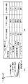
本実施形態の歪み補正量算出部106には、ブレ検出部105により検出された、1フレームの画像の撮像中に生じた角速度変化の情報に加え、当該画像の撮像時のデジタルビデオカメラ100の状態を示す補助情報が制御部101により入力される。補助情報とは、例えば不図示のジャイロセンサの最大加速度(ジャイロデータ)、焦点距離、主被写体情報、あるいはシャッタスピード等の情報であり、本実施形態では当該補助情報は補助情報解析部211に入力される。
The distortion correction
補助情報解析部211は、入力された補助情報から、デジタルビデオカメラ100の撮影状況が、両手持ち撮影、片手持ち撮影、及び歩き撮り撮影のいずれであるかを推定する。一般的にこれらの撮影状況では、撮影者による把持方法や移動状態により、デジタルビデオカメラ100に生じうる手ぶれの周波数分布が図9(a)のように異なる。具体的には、移動しながらの撮影である歩き撮り撮影では、手ぶれによるブレ量は相対的に大きくなり、これに対して撮影者が移動せずに両手でデジタルビデオカメラ100を構える両手持ち撮影では、手ぶれによるブレ量は相対的に小さくなると考えられる。
The auxiliary
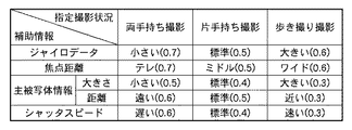
ジャイロデータについては、例えば2〜3Hz程度の1つの低周波を検波することで、当該周波数におけるブレ量を、閾値を用いて「大きい」、「標準」、及び「小さい」のいずれかに分類する。そして補助情報解析部211は、ブレ量が大きい場合は「歩き撮り撮影」、小さい場合は「両手持ち撮影」と推定する。
For gyro data, for example, by detecting one low frequency of about 2 to 3 Hz, the amount of blur at the frequency is classified into “large”, “standard”, and “small” using a threshold value. . The auxiliary
焦点距離については、ズーム位置がテレ寄りであるほど、手ぶれが像の歪みとして現れやすいため、撮影者はデジタルビデオカメラ100をしっかりと固定して撮影する状況が推定される。即ち、補助情報解析部211は、焦点距離が長い場合は「両手持ち撮影」、焦点距離が短い場合は「歩き撮り撮影」と推定する。
Regarding the focal length, as the zoom position is closer to the telephoto, camera shake is more likely to appear as image distortion. Therefore, it is estimated that the photographer is shooting with the
主被写体情報については、ズーム位置がワイド時の撮像画像における主被写体の大きさが小さい、あるいは主被写体までの距離が遠い場合、即ちズーム位置をテレ寄りにした撮影がなされると思われる。即ち、補助情報解析部211は、主被写体の大きさが小さい、あるいは主被写体までの距離が遠い場合は「両手持ち撮影」、主被写体の大きさが大きい、あるいは主被写体までの距離が近い場合は「歩き撮り撮影」と推定する。
As for the main subject information, it is considered that the main subject in the captured image when the zoom position is wide is small or the distance to the main subject is long, that is, the zoom position is telephoto. That is, the auxiliary
シャッタスピードについては、露光時間が長い場合は蓄積ブレの影響が大きくなり、低周波のブレに起因する撮像画像の歪みは目立ちにくくなると考えられる。即ち、補助情報解析部211は、シャッタスピードが遅い場合は低周波成分のブレ量が少ない「両手持ち撮影」と推定し、位相補償周波数を高周波側に寄せる。
Regarding the shutter speed, when the exposure time is long, the influence of the accumulated blur becomes large, and it is considered that the distortion of the captured image due to the low-frequency blur becomes inconspicuous. That is, when the shutter speed is slow, the auxiliary
即ち、補助情報解析部211は、入力された補助情報のそれぞれについて、予め定められた状態や閾値を用いて、それぞれのパラメータを図9(b)のように分類し、補助情報のパラメータごとに撮影状況を推定する。このようにすることで、一般的なブレ量の周波数分布から実際の手ぶれの時間特性の中心周波数を決定するために検波する周波数を、後述の検波周波数決定部212で決定することができる。
That is, the auxiliary
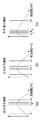
検波周波数決定部212は、補助情報解析部211で推定された補助情報のパラメータごとの撮影状況から、実際の手ぶれの時間特性についてのブレ量の周波数分布を検波する周波数(検波周波数)を決定(第1の選択)する。撮像画像における歪み量の周波数分布を考えると、中心周波数が撮影状況ごとに例えば図10のような傾向になるため、当該傾向に基づいて、実際の手ぶれの時間特性の中心周波数は推定可能である。即ち、このように推定された中心周波数近傍の周波数について、重点的に実際の手ぶれの時間特性についてのブレ量の周波数分布を検波すれば、実際の中心周波数を簡易的に特定可能であると考えられる。
The detection
検波周波数決定部212は、まず補助情報のそれぞれのパラメータに対する検波周波数を離散的に選択する。具体的には検波周波数決定部212は、補助情報のそれぞれのパラメータについて推定された撮影状況に対応した、図11のような一般的なブレ量の周波数分布の中心周波数に基づいて予め設定された離散的な検波周波数のセットを、当該パラメータごとに選択する。
The detection
そして検波周波数決定部212は、補助情報のそれぞれのパラメータに対して選択された離散的な検波周波数のセットを組み合わせて、後述するブレ量検波部213で実際の手ぶれの時間特性を検波する最終的な検波周波数のセットを決定する。
Then, the detection
例えば、補助情報の2つのパラメータを用いて最終的な検波周波数のセットを決定する場合を考える。1つのパラメータについて選択された検波周波数のセットが図12(a)であり、もう一方のパラメータについて選択された検波周波数のセットが図12(b)である場合、最終的な検波周波数のセットは1番目から5番目それぞれの周波数の平均をとり、
1番目:(2+2)/2=2Hz
2番目:(3+7)/2=5Hz
3番目:(4+8)/2=6Hz
4番目:(5+9)/2=7Hz
5番目:(12+12)/2=12Hz
となる(図12(c)に示される)。
For example, consider a case where a final set of detection frequencies is determined using two parameters of auxiliary information. When the set of detection frequencies selected for one parameter is FIG. 12 (a) and the set of detection frequencies selected for the other parameter is FIG. 12 (b), the final set of detection frequencies is Take the average of the 1st to 5th frequencies,
First: (2 + 2) / 2 = 2Hz
2nd: (3 + 7) / 2 = 5Hz
3rd: (4 + 8) / 2 = 6Hz
4th: (5 + 9) / 2 = 7Hz
5th: (12 + 12) / 2 = 12Hz
(Shown in FIG. 12 (c)).
このようにすることで、離散的に決定された周波数に対して、実際の手ぶれの時間特性からブレ量の周波数分布を検波するため、全周波数に対するブレ量の周波数分布の解析(検波)より、当該処理に係る処理負荷を軽減できる。 By doing so, in order to detect the frequency distribution of the shake amount from the time characteristics of the actual camera shake with respect to the discretely determined frequency, from the analysis (detection) of the shake amount frequency distribution for all frequencies, The processing load related to the processing can be reduced.
ブレ量検波部213は、入力された手ぶれの時間特性について、検波周波数決定部212で決定された検波周波数のセットに含まれる周波数について離散フーリエ変換し、それぞれの周波数のブレ量の周波数分布を得る。得られるブレ量の周波数分布は、例えば図13のように離散的となる。中心周波数決定部203は、当該周波数分布に対して2π・cos(ωt0)・Δtを乗算することにより、極大の歪み量を示す周波数を中心周波数として決定する。
The shake
以上説明したように、本実施形態の撮像装置は、撮影状況を推定して検波周波数を決定することにより、手ぶれの時間特性の中心周波数を算出する処理を軽減することができる。このようにして得られた中心周波数を用いることで、上述の実施形態1と同様に少なくとも、補整残りあるいは過補正による歪みが目立ちやすい周波数について、IIRフィルタを用いたことによる位相ズレを補償することができる。 As described above, the imaging apparatus according to the present embodiment can reduce the processing for calculating the center frequency of the time characteristic of camera shake by estimating the imaging situation and determining the detection frequency. By using the center frequency obtained in this way, the phase shift due to the use of the IIR filter is compensated for at least the frequency that remains as a correction residue or distortion due to overcorrection as in the first embodiment. Can do.
(変形例1)
上述した実施形態2では、検波周波数決定部212は補助情報のパラメータそれぞれについて選択された固定の検波周波数のセットの平均をとって、実際の手ぶれの時間特性を検波する検波周波数のセットを決定するものとして説明した。本変形例1では、補助情報のパラメータそれぞれについて推定した撮影状況について信頼度を設け、各撮影状況の中心周波数の信頼度に基づいて検波周波数のセットを決定する方法について説明する。
(Modification 1)
In the second embodiment described above, the detection
例えば、補助情報のパラメータそれぞれについて推定した撮影状況について、図14に示すような推定の信頼度が設定されている場合を考える。検波周波数決定部212は、補助情報解析部211により補助情報のパラメータそれぞれについて推定された撮影状況に対して、予め定められた図10のような中心周波数を選択し、当該中心周波数を中心として検波周波数のセットを選択する。
For example, let us consider a case where the estimation reliability as shown in FIG. 14 is set for the shooting situation estimated for each parameter of the auxiliary information. The detection
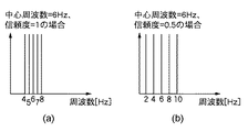
例えば、推定された撮影状況の信頼度が1である場合、図15(a)に示すように中心周波数6Hzを中心とした検波周波数のセットが、1Hz間隔の4、5、6、7、8Hzの周波数となるように設定されているとする。検波周波数決定部212は、補助情報の1つのパラメータの推定された撮影状況の信頼度が0.5である場合、信頼度1の検波周波数のセットに比べ、検波周波数のセットの間隔が当該撮影状況の信頼度の逆数、即ち2倍となるように検波周波数のセットを選択する。つまり、推定された撮影状況の中心周波数6Hzを中心として、検波する周波数の周波数間隔が2倍である2Hz間隔となる、図15(b)のような検波周波数のセットが当該パラメータに対して選択される。
For example, when the reliability of the estimated imaging situation is 1, as shown in FIG. 15A, a set of detection frequencies centered on a center frequency of 6 Hz is 4, 5, 6, 7, 8 Hz at 1 Hz intervals. It is assumed that the frequency is set to be. When the reliability of the estimated imaging state of one parameter of the auxiliary information is 0.5, the detection
そして検波周波数決定部212は、補助情報のパラメータそれぞれについて撮影状況の信頼度に基づいて選択された検波周波数のセットを平均することにより、実際の手ぶれの時間特性を検波する、最終的な検波周波数のセットを決定する。
Then, the detection
このように、補助情報である撮影時のデジタルビデオカメラ100の状態に応じて、撮影状況を推定する際に、推定の信頼度を用いることで、より撮影時の状態に柔軟に対応した検波周波数を用いて、手ぶれの時間特性の検波を実行することができる。
In this way, when estimating the shooting state according to the state of the
なお、本変形例の説明において、検波周波数のセットは、周波数の間隔が信頼度の逆数となるように中心周波数を中心として選択されるものとして説明したが、本発明の実施はこれに限らない。例えば、信頼度ごとに周波数の間隔が予め定められていてもよいし、中心周波数に応じて周波数の間隔が変化してもよい。あるいは、検波周波数のセットにおける周波数の間隔は、等間隔でなくてもよい。 In the description of the present modification, the set of detection frequencies has been described as being centered on the center frequency so that the frequency interval is the inverse of the reliability. However, the present invention is not limited to this. . For example, the frequency interval may be determined in advance for each reliability, or the frequency interval may change according to the center frequency. Alternatively, the frequency intervals in the set of detection frequencies may not be equal.
(変形例2)
上述した実施形態1及び変形例1では、検波周波数決定部212が決定した検波周波数のセットについて検波を行って、手ぶれの時間特性についての中心周波数を、当該検波周波数のセットのうち、歪み量が極大となる周波数に決定するものとして説明した。本変形例ではさらに、検波周波数で手ぶれの時間特性を検波した結果の歪み量の周波数分布をフィードバックすることにより、より正確な中心周波数を決定する方法について説明する。
(Modification 2)
In the first embodiment and the first modification described above, the detection frequency set determined by the detection
(歪み補正量算出部106の内部構成)
図2(c)は、本変形例に係る歪み補正量算出部106の内部構成を示した図である。なお、本実施形態の歪み補正量算出部106において、上述した実施形態1及び実施形態2と同一の構成については、同一の参照符号を付して説明を省略し、本実施形態に特徴的な構成あるいは処理の説明に留める。
(Internal configuration of distortion correction amount calculation unit 106)
FIG. 2C is a diagram illustrating an internal configuration of the distortion correction
検波周波数調整部221は、中心周波数決定部203で得られた手ぶれの時間特性を検波した結果の歪み量の周波数分布に基づいて、ブレ量検波部213で検波に用いる検波周波数のセットを制御するブロックである。
The detection
例えば中心周波数決定部203で、検波周波数についてのブレ量の周波数分布に対して、2π・cos(ωt0)・Δtが乗じられることにより得られた、撮像画像における歪み量の周波数分布が図16(a)のようであった場合を考える。当該周波数分布では、極大の歪み量を有する周波数が4Hzであり、当該周波数を挟む周波数である2Hz及び6Hzにおいて歪み量が減少しているため、手ぶれの時間特性の正確な中心周波数は2〜6Hzの周波数帯に存在すると考えられる。
For example, the frequency distribution of the distortion amount in the captured image obtained by multiplying the frequency distribution of the blur amount for the detection frequency by 2π · cos (ωt 0 ) · Δt by the center
検波周波数調整部221は、周波数分布の結果を中心周波数決定部203より入力されると、上述のような傾向を判別し、検波周波数決定部212から入力されて1度ブレ量検波部213に出力した検波周波数のセットを変更する。例えば図16(a)のような周波数分布の結果である場合は、図16(b)のように検波周波数の中心である周波数をシフトして新たな検波周波数のセットを設定(第2の選択)し、ブレ量検波部213に出力する。
When the frequency distribution result is input from the center
このようにすることで、中心周波数決定部203は複数回の検波結果を用いて中心周波数を決定することが可能になるため、よりIIRフィルタ301による位相ズレの補償精度を向上させることができる。
By doing so, the center
なお、上述した変形例1及び2は、別々の実施形態として説明したが、当該変形例が組み合わせ可能であることは、容易に想像されよう。
In addition, although the
(その他の実施形態)
また、本発明は、以下の処理を実行することによっても実現される。即ち、上述した実施形態の機能を実現するソフトウェア(プログラム)を、ネットワーク又は各種記憶媒体を介してシステム或いは装置に供給し、そのシステム或いは装置のコンピュータ(またはCPUやMPU等)がプログラムを読み出して実行する処理である。
(Other embodiments)
The present invention can also be realized by executing the following processing. That is, software (program) that realizes the functions of the above-described embodiments is supplied to a system or apparatus via a network or various storage media, and a computer (or CPU, MPU, or the like) of the system or apparatus reads the program. It is a process to be executed.
Claims (9)
前記撮像素子を用いて画像を撮像する場合に、当該撮像素子の露光期間における前記撮像装置の振動を検出する検出手段と、
前記検出手段により検出された前記振動の時間特性を取得する取得手段と、
前記振動の時間特性について、前記振動に起因して前記画像に生じる被写体像の歪み量の周波数分布を解析する解析手段と、
前記歪み量の周波数分布から、当該歪み量が極大となる周波数を前記歪み量の中心周波数として決定する決定手段と、
少なくとも前記中心周波数について、前記取得手段により生じた位相ズレがなくなるように、前記振動の時間特性を補償する補償手段と、
前記補償手段により補償された前記振動から算出された補正量を用いて、前記撮像素子のラインごとに前記振動に起因して生じた被写体像の歪みを補正する補正手段と、
を備えることを特徴とする撮像装置。 An image pickup apparatus including an image pickup element driven by a rolling shutter method,
Detecting means for detecting vibrations of the imaging device during an exposure period of the imaging element when an image is captured using the imaging element;
Obtaining means for obtaining a time characteristic of the vibration detected by the detecting means;
Analyzing means for analyzing the frequency distribution of the distortion amount of the subject image generated in the image due to the vibration with respect to the time characteristics of the vibration;
Determining means for determining, from the frequency distribution of the distortion amount, a frequency at which the distortion amount is maximized as a center frequency of the distortion amount;
Compensation means for compensating the time characteristics of the vibration so that there is no phase shift caused by the acquisition means at least for the center frequency;
Correction means for correcting distortion of the subject image caused by the vibration for each line of the image sensor using a correction amount calculated from the vibration compensated by the compensation means;
An imaging apparatus comprising:
前記撮像素子を用いて画像を撮像する場合に、当該撮像素子の露光期間における前記撮像装置の振動を検出する検出手段と、
前記検出手段により検出された前記振動の時間特性を取得する取得手段と、
前記画像を撮像時の前記撮像装置のパラメータに基づいて、前記振動に起因して前記画像に生じる被写体像の歪み量の中心周波数が存在すると推定される周波数帯を含む複数の周波数を検波周波数として選択する第1の選択手段と、
前記振動の時間特性について、前記振動のうちの前記検波周波数に起因して前記画像に生じる被写体像の歪み量の周波数分布を解析する解析手段と、
前記歪み量の周波数分布から、当該歪み量が極大となる周波数を前記歪み量の中心周波数として決定する決定手段と、
少なくとも前記中心周波数について、前記取得手段により生じた位相ズレがなくなるように、前記振動の時間特性を補償する補償手段と、
前記補償手段により補償された前記振動から算出された補正量を用いて、前記撮像素子のラインごとに前記振動に起因して生じた被写体像の歪みを補正する補正手段と、
を備えることを特徴とする撮像装置。 An image pickup apparatus including an image pickup element driven by a rolling shutter method,
Detecting means for detecting vibrations of the imaging device during an exposure period of the imaging element when an image is captured using the imaging element;
Obtaining means for obtaining a time characteristic of the vibration detected by the detecting means;
Based on the parameters of the imaging device at the time of capturing the image, a plurality of frequencies including a frequency band in which the center frequency of the distortion amount of the subject image generated in the image due to the vibration is estimated as a detection frequency First selecting means for selecting;
Analyzing means for analyzing the frequency distribution of the distortion amount of the subject image generated in the image due to the detection frequency of the vibration with respect to the time characteristics of the vibration;
Determining means for determining, from the frequency distribution of the distortion amount, a frequency at which the distortion amount is maximized as a center frequency of the distortion amount;
Compensation means for compensating the time characteristics of the vibration so that there is no phase shift caused by the acquisition means at least for the center frequency;
Correction means for correcting distortion of the subject image caused by the vibration for each line of the image sensor using a correction amount calculated from the vibration compensated by the compensation means;
An imaging apparatus comprising:
前記解析手段は、前記振動の時間特性について前記振動のうちの前記新たな検波周波数に起因して前記画像に生じる被写体像の歪み量の周波数分布を解析し、
前記決定手段は、前記検波周波数についての歪み量の周波数分布、及び前記新たな検波周波数についての歪み量の周波数分布を用いて、前記中心周波数を決定することを特徴とする請求項2に記載の撮像装置。 Based on the frequency distribution of the distortion amount analyzed by the analysis means, further comprising second selection means for selecting a new detection frequency different from the detection frequency,
The analysis means analyzes the frequency distribution of the distortion amount of the subject image generated in the image due to the new detection frequency of the vibration with respect to the time characteristic of the vibration,
The said determination means determines the said center frequency using the frequency distribution of the distortion amount about the said detection frequency, and the frequency distribution of the distortion amount about the said new detection frequency, The said center frequency is characterized by the above-mentioned. Imaging device.
前記第1の選択手段は、前記撮像時のパラメータに基づいて前記画像を撮像時の前記撮像装置の撮影状況を推定し、当該推定された撮影状況ごとに予め定められた周波数を用いて前記検波周波数を選択することを特徴とする請求項2または3に記載の撮像装置。 The parameter at the time of imaging is at least one of vibration at the time of imaging, focal length, main subject information, and shutter speed,
The first selection unit estimates a shooting situation of the imaging device at the time of shooting the image based on the parameters at the time of shooting, and uses the frequency determined in advance for each of the estimated shooting situations. The imaging apparatus according to claim 2, wherein a frequency is selected.
検出手段が、前記撮像素子を用いて画像を撮像する場合に、当該撮像素子の露光期間における前記撮像装置の振動を検出する検出工程と、
取得手段が、前記検出工程において検出された前記振動の時間特性を取得する取得工程と、
解析手段が、前記振動の時間特性について、前記振動に起因して前記画像に生じる被写体像の歪み量の周波数分布を解析する解析工程と、
決定手段が、前記歪み量の周波数分布から、当該歪み量が極大となる周波数を前記歪み量の中心周波数として決定する決定工程と、
補償手段が、少なくとも前記中心周波数について、前記取得工程において生じた位相ズレがなくなるように、前記振動の時間特性を補償する補償工程と、
補正手段が、前記補償工程において補償された前記振動から算出された補正量を用いて、前記撮像素子のラインごとに前記振動に起因して生じた被写体像の歪みを補正する補正工程と、
を備えることを特徴とする撮像装置の制御方法。 A method for controlling an imaging apparatus including an imaging element driven by a rolling shutter system,
A detection step of detecting vibrations of the imaging device during an exposure period of the imaging device when the detection means captures an image using the imaging device;
An acquisition step in which an acquisition unit acquires a time characteristic of the vibration detected in the detection step;
An analysis step for analyzing a frequency distribution of a distortion amount of a subject image generated in the image due to the vibration with respect to a time characteristic of the vibration; and
A determining step for determining, from the frequency distribution of the distortion amount, a frequency at which the distortion amount is maximized as a center frequency of the distortion amount;
A compensating step for compensating a time characteristic of the vibration so that a compensation means eliminates a phase shift generated in the obtaining step at least for the center frequency;
A correcting step for correcting distortion of a subject image caused by the vibration for each line of the image sensor using a correction amount calculated from the vibration compensated in the compensating step;
An image pickup apparatus control method comprising:
検出手段が、前記撮像素子を用いて画像を撮像する場合に、当該撮像素子の露光期間における前記撮像装置の振動を検出する検出工程と、
取得手段が、前記検出工程において検出された前記振動の時間特性を取得する取得工程と、
第1の選択手段が、前記画像の撮像時のパラメータから、前記振動に起因して前記画像に生じる被写体像の歪み量の中心周波数が存在すると推定される周波数帯を含む複数の周波数を検波周波数として選択する第1の選択工程と、
解析手段が、前記振動の時間特性について、前記振動のうちの前記検波周波数に起因して前記画像に生じる被写体像の歪み量の周波数分布を解析する解析工程と、
決定手段が、前記歪み量の周波数分布から、当該歪み量が極大となる周波数を前記歪み量の中心周波数として決定する決定工程と、
補償手段が、少なくとも前記中心周波数について、前記取得工程において生じた位相ズレがなくなるように、前記振動の時間特性を補償する補償工程と、
補正手段が、前記補償工程において補償された前記振動から算出された補正量を用いて、前記撮像素子のラインごとに前記振動に起因して生じた被写体像の歪みを補正する補正工程と、
を備えることを特徴とする撮像装置の制御方法。 A method for controlling an imaging apparatus including an imaging element driven by a rolling shutter system,
A detection step of detecting vibrations of the imaging device during an exposure period of the imaging device when the detection means captures an image using the imaging device;
An acquisition step in which an acquisition unit acquires a time characteristic of the vibration detected in the detection step;
The first selection means detects a plurality of frequencies including a frequency band in which a center frequency of a distortion amount of a subject image generated in the image due to the vibration exists from a parameter at the time of capturing the image. A first selection step to select as
An analyzing step for analyzing a frequency distribution of a distortion amount of a subject image generated in the image due to the detection frequency of the vibration with respect to a time characteristic of the vibration;
A determining step for determining, from the frequency distribution of the distortion amount, a frequency at which the distortion amount is maximized as a center frequency of the distortion amount;
A compensating step for compensating a time characteristic of the vibration so that a compensation means eliminates a phase shift generated in the obtaining step at least for the center frequency;
A correcting step for correcting distortion of a subject image caused by the vibration for each line of the image sensor using a correction amount calculated from the vibration compensated in the compensating step;
An image pickup apparatus control method comprising:
Priority Applications (3)
| Application Number | Priority Date | Filing Date | Title |
|---|---|---|---|
| JP2011062925A JP5249377B2 (en) | 2011-03-22 | 2011-03-22 | Imaging apparatus, control method therefor, and program |
| US13/407,897 US8970712B2 (en) | 2011-03-22 | 2012-02-29 | Image sensing apparatus for correcting image distortion caused by hand shake, and control method thereof |
| CN201210078556.3A CN102694979B (en) | 2011-03-22 | 2012-03-22 | The control method of picture pick-up device and picture pick-up device |
Applications Claiming Priority (1)
| Application Number | Priority Date | Filing Date | Title |
|---|---|---|---|
| JP2011062925A JP5249377B2 (en) | 2011-03-22 | 2011-03-22 | Imaging apparatus, control method therefor, and program |
Publications (2)
| Publication Number | Publication Date |
|---|---|
| JP2012199802A true JP2012199802A (en) | 2012-10-18 |
| JP5249377B2 JP5249377B2 (en) | 2013-07-31 |
Family
ID=46860246
Family Applications (1)
| Application Number | Title | Priority Date | Filing Date |
|---|---|---|---|
| JP2011062925A Active JP5249377B2 (en) | 2011-03-22 | 2011-03-22 | Imaging apparatus, control method therefor, and program |
Country Status (3)
| Country | Link |
|---|---|
| US (1) | US8970712B2 (en) |
| JP (1) | JP5249377B2 (en) |
| CN (1) | CN102694979B (en) |
Cited By (1)
| Publication number | Priority date | Publication date | Assignee | Title |
|---|---|---|---|---|
| WO2015190317A1 (en) * | 2014-06-11 | 2015-12-17 | ソニー株式会社 | Image processing device, image processing method, and program |
Families Citing this family (24)
| Publication number | Priority date | Publication date | Assignee | Title |
|---|---|---|---|---|
| US9460495B2 (en) * | 2012-04-06 | 2016-10-04 | Microsoft Technology Licensing, Llc | Joint video stabilization and rolling shutter correction on a generic platform |
| WO2014068779A1 (en) * | 2012-11-05 | 2014-05-08 | 株式会社モルフォ | Image processing device, image processing method, image processing program, and storage medium |
| JP5794705B2 (en) * | 2013-02-01 | 2015-10-14 | キヤノン株式会社 | Imaging apparatus, control method thereof, and program |
| JP6097936B2 (en) * | 2013-03-22 | 2017-03-22 | パナソニックIpマネジメント株式会社 | Image stabilizer, interchangeable lens, camera system |
| US10136063B2 (en) * | 2013-07-12 | 2018-11-20 | Hanwha Aerospace Co., Ltd | Image stabilizing method and apparatus |
| JP6150655B2 (en) * | 2013-08-01 | 2017-06-21 | キヤノン株式会社 | Image shake correction apparatus and control method therefor, lens barrel, optical apparatus, and imaging apparatus |
| JP6257207B2 (en) * | 2013-08-01 | 2018-01-10 | キヤノン株式会社 | Image shake correction apparatus and control method therefor, lens barrel, and imaging apparatus |
| CN103841336B (en) * | 2014-03-28 | 2016-09-28 | 深圳市大疆创新科技有限公司 | Imaging device and shutter control method thereof |
| JP6096382B2 (en) * | 2014-04-11 | 2017-03-15 | 富士フイルム株式会社 | Image processing apparatus, imaging apparatus, image processing method, and program |
| JP2016019076A (en) * | 2014-07-07 | 2016-02-01 | ソニー株式会社 | IMAGING DEVICE, IMAGING METHOD, PROGRAM, AND REPRODUCTION DEVICE |
| FR3027143B1 (en) * | 2014-10-10 | 2016-11-11 | Parrot | MOBILE APPARATUS, IN PARTICULAR ROTATING SAIL DRONE, PROVIDED WITH A VIDEO CAMERA DELIVERING IMAGE SEQUENCES DYNAMICALLY CORRECTED BY THE "WOBBLE" EFFECT |
| JP6598549B2 (en) * | 2015-07-23 | 2019-10-30 | キヤノン株式会社 | Image processing apparatus and control method thereof, imaging apparatus and control method thereof |
| CN105657273B (en) * | 2016-02-19 | 2018-09-04 | 广东欧珀移动通信有限公司 | Setting method, device and the mobile terminal of safety shutter time |
| CN107493686B (en) * | 2016-04-13 | 2019-11-29 | 华为技术有限公司 | A kind of method, apparatus and camera installation setting exposure time |
| CN106027885B (en) * | 2016-05-18 | 2020-01-10 | Oppo广东移动通信有限公司 | Electronic device method and device, first electronic device and second electronic device |
| WO2017206079A1 (en) * | 2016-05-31 | 2017-12-07 | 深圳曼塔智能科技有限公司 | Unmanned aerial vehicle, and device and method for image anti-jitter thereof |
| CN110166697B (en) * | 2019-06-28 | 2021-08-31 | Oppo广东移动通信有限公司 | Camera anti-shake method, device, electronic device and computer-readable storage medium |
| CN112308783B (en) * | 2019-07-24 | 2024-06-28 | 株式会社理光 | Rolling shutter effect correction method, device and computer readable storage medium |
| WO2021070173A2 (en) * | 2019-10-07 | 2021-04-15 | Inspekto A.M.V. Ltd | Motion in images used in a visual inspection process |
| CN112161694B (en) * | 2020-09-21 | 2022-07-05 | 武汉大学 | Method for measuring error of high-speed camera caused by environmental excitation |
| CN112215782B (en) * | 2020-10-29 | 2022-10-14 | 中国科学院长春光学精密机械与物理研究所 | A method and device for image correction of a rolling shutter imaging device |
| CN112637496B (en) * | 2020-12-21 | 2022-05-31 | 维沃移动通信有限公司 | Image correction method and device |
| CN113472991B (en) * | 2021-07-09 | 2023-04-25 | Oppo广东移动通信有限公司 | Control method, control device, camera assembly, electronic device and medium |
| CN115696047B (en) * | 2022-09-23 | 2026-02-06 | Oppo广东移动通信有限公司 | Anti-shake method and device, storage medium and electronic equipment |
Citations (2)
| Publication number | Priority date | Publication date | Assignee | Title |
|---|---|---|---|---|
| JP2007189602A (en) * | 2006-01-16 | 2007-07-26 | Pentax Corp | Imaging device |
| JP2010016700A (en) * | 2008-07-04 | 2010-01-21 | Canon Inc | Vibration correcting device |
Family Cites Families (5)
| Publication number | Priority date | Publication date | Assignee | Title |
|---|---|---|---|---|
| JP4389779B2 (en) | 2004-12-27 | 2009-12-24 | ソニー株式会社 | Method for correcting distortion of captured image signal and distortion correction apparatus for captured image signal |
| US8139149B2 (en) * | 2006-03-22 | 2012-03-20 | Victor Company Of Japan, Limited | Still image acquisition device, still image acquisition method, and image fluctuation correction device |
| KR20090123901A (en) * | 2007-03-23 | 2009-12-02 | 가부시끼가이샤 도시바 | Image stabilization device, image pickup device, computer readable recording medium recording image stabilization program, computer readable recording medium recording image recording program, image stabilization method, image pickup method |
| JP5298269B2 (en) * | 2007-12-25 | 2013-09-25 | セミコンダクター・コンポーネンツ・インダストリーズ・リミテッド・ライアビリティ・カンパニー | Vibration compensation control circuit |
| JP2011039340A (en) * | 2009-08-13 | 2011-02-24 | Sony Corp | Image capturing apparatus |
-
2011
- 2011-03-22 JP JP2011062925A patent/JP5249377B2/en active Active
-
2012
- 2012-02-29 US US13/407,897 patent/US8970712B2/en not_active Expired - Fee Related
- 2012-03-22 CN CN201210078556.3A patent/CN102694979B/en not_active Expired - Fee Related
Patent Citations (2)
| Publication number | Priority date | Publication date | Assignee | Title |
|---|---|---|---|---|
| JP2007189602A (en) * | 2006-01-16 | 2007-07-26 | Pentax Corp | Imaging device |
| JP2010016700A (en) * | 2008-07-04 | 2010-01-21 | Canon Inc | Vibration correcting device |
Cited By (3)
| Publication number | Priority date | Publication date | Assignee | Title |
|---|---|---|---|---|
| WO2015190317A1 (en) * | 2014-06-11 | 2015-12-17 | ソニー株式会社 | Image processing device, image processing method, and program |
| JP2016001771A (en) * | 2014-06-11 | 2016-01-07 | ソニー株式会社 | Image processor, image processing method and program |
| US9906693B2 (en) | 2014-06-11 | 2018-02-27 | Sony Semiconductor Solutions Corporation | Image processing apparatus, image processing method, and program |
Also Published As
| Publication number | Publication date |
|---|---|
| JP5249377B2 (en) | 2013-07-31 |
| US8970712B2 (en) | 2015-03-03 |
| CN102694979B (en) | 2016-01-20 |
| CN102694979A (en) | 2012-09-26 |
| US20120242847A1 (en) | 2012-09-27 |
Similar Documents
| Publication | Publication Date | Title |
|---|---|---|
| JP5249377B2 (en) | Imaging apparatus, control method therefor, and program | |
| JP5501119B2 (en) | Imaging apparatus and control method thereof | |
| JP7277513B2 (en) | a lens device, a lens device control method, and a lens device control program; | |
| JP5553597B2 (en) | Imaging apparatus and control method thereof | |
| JP5409342B2 (en) | Imaging apparatus and control method thereof | |
| US10425584B2 (en) | Image pickup system, control method thereof, image pickup apparatus, and lens device | |
| JP6478504B2 (en) | Imaging apparatus and control method thereof | |
| JP6530602B2 (en) | Image pickup apparatus and control method thereof | |
| JP6108940B2 (en) | Image blur correction apparatus, control method therefor, program, and storage medium | |
| JP2011139167A5 (en) | Imaging apparatus and control method thereof | |
| JP2017090580A (en) | Image blur correction apparatus and method | |
| US20150256753A1 (en) | Image stabilization apparatus, method of controlling the same, image capturing apparatus, lens apparatus, and storage medium | |
| JP2012058545A (en) | Imaging device | |
| JP5249378B2 (en) | Imaging apparatus, control method therefor, and program | |
| JP5247782B2 (en) | Optical apparatus, imaging apparatus including the same, and control method of optical apparatus | |
| JP2007114466A (en) | An imaging device having an image stabilization function | |
| JP3865126B2 (en) | Image processing apparatus and method, recording medium, and program | |
| US10771700B2 (en) | Image blur correction apparatus, interchangeable lens, camera body, image blur correction method, and storage medium | |
| US10848675B2 (en) | Image blur correction apparatus, camera body, image blur correction method, and storage medium | |
| JP7236268B2 (en) | Image blur correction device, interchangeable lens, camera body, image blur correction method, and program | |
| US11863870B2 (en) | Image stabilization apparatus and method of controlling the same | |
| JP2014126859A (en) | Imaging apparatus, method of controlling the same, program and storage medium | |
| JP2003234946A (en) | Image processing apparatus and method, recording medium, and program | |
| JP7214424B2 (en) | Imaging device and its control method | |
| JP7599855B2 (en) | Imaging device and control method thereof |
Legal Events
| Date | Code | Title | Description |
|---|---|---|---|
| A131 | Notification of reasons for refusal |
Free format text: JAPANESE INTERMEDIATE CODE: A131 Effective date: 20121221 |
|
| A521 | Request for written amendment filed |
Free format text: JAPANESE INTERMEDIATE CODE: A523 Effective date: 20130218 |
|
| TRDD | Decision of grant or rejection written | ||
| A01 | Written decision to grant a patent or to grant a registration (utility model) |
Free format text: JAPANESE INTERMEDIATE CODE: A01 Effective date: 20130315 |
|
| A61 | First payment of annual fees (during grant procedure) |
Free format text: JAPANESE INTERMEDIATE CODE: A61 Effective date: 20130411 |
|
| FPAY | Renewal fee payment (event date is renewal date of database) |
Free format text: PAYMENT UNTIL: 20160419 Year of fee payment: 3 |