JP2012201030A - 金型装置およびインサート成形品の製造方法 - Google Patents
金型装置およびインサート成形品の製造方法 Download PDFInfo
- Publication number
- JP2012201030A JP2012201030A JP2011068765A JP2011068765A JP2012201030A JP 2012201030 A JP2012201030 A JP 2012201030A JP 2011068765 A JP2011068765 A JP 2011068765A JP 2011068765 A JP2011068765 A JP 2011068765A JP 2012201030 A JP2012201030 A JP 2012201030A
- Authority
- JP
- Japan
- Prior art keywords
- metal plate
- cavity
- mold
- resin material
- pressing
- Prior art date
- Legal status (The legal status is an assumption and is not a legal conclusion. Google has not performed a legal analysis and makes no representation as to the accuracy of the status listed.)
- Granted
Links
- 238000004519 manufacturing process Methods 0.000 title claims description 12
- 239000002184 metal Substances 0.000 claims abstract description 122
- 239000011347 resin Substances 0.000 claims abstract description 60
- 229920005989 resin Polymers 0.000 claims abstract description 60
- 239000000463 material Substances 0.000 claims abstract description 57
- 238000010438 heat treatment Methods 0.000 claims description 45
- 238000002347 injection Methods 0.000 claims description 15
- 239000007924 injection Substances 0.000 claims description 15
- 238000001816 cooling Methods 0.000 claims description 4
- 230000010354 integration Effects 0.000 claims description 3
- 238000000465 moulding Methods 0.000 abstract description 13
- 238000003825 pressing Methods 0.000 description 137
- 230000002093 peripheral effect Effects 0.000 description 15
- 230000005855 radiation Effects 0.000 description 11
- 238000000034 method Methods 0.000 description 9
- 239000004745 nonwoven fabric Substances 0.000 description 8
- 229920000139 polyethylene terephthalate Polymers 0.000 description 8
- 239000005020 polyethylene terephthalate Substances 0.000 description 8
- 239000010687 lubricating oil Substances 0.000 description 7
- 230000000052 comparative effect Effects 0.000 description 6
- 230000005674 electromagnetic induction Effects 0.000 description 5
- 239000010410 layer Substances 0.000 description 5
- -1 polytetrafluoroethylene Polymers 0.000 description 5
- 229920000106 Liquid crystal polymer Polymers 0.000 description 4
- 239000004977 Liquid-crystal polymers (LCPs) Substances 0.000 description 4
- 229910052736 halogen Inorganic materials 0.000 description 4
- 150000002367 halogens Chemical class 0.000 description 4
- 239000012212 insulator Substances 0.000 description 4
- 238000005452 bending Methods 0.000 description 3
- 230000005540 biological transmission Effects 0.000 description 3
- 238000004140 cleaning Methods 0.000 description 3
- 239000003086 colorant Substances 0.000 description 3
- 230000008602 contraction Effects 0.000 description 3
- 230000000694 effects Effects 0.000 description 3
- 230000015572 biosynthetic process Effects 0.000 description 2
- 238000000605 extraction Methods 0.000 description 2
- 239000000314 lubricant Substances 0.000 description 2
- 229920001343 polytetrafluoroethylene Polymers 0.000 description 2
- 239000004810 polytetrafluoroethylene Substances 0.000 description 2
- 229910000831 Steel Inorganic materials 0.000 description 1
- 238000010586 diagram Methods 0.000 description 1
- 238000002844 melting Methods 0.000 description 1
- 230000008018 melting Effects 0.000 description 1
- 239000003921 oil Substances 0.000 description 1
- 230000000630 rising effect Effects 0.000 description 1
- 238000005096 rolling process Methods 0.000 description 1
- 238000007790 scraping Methods 0.000 description 1
- 239000010959 steel Substances 0.000 description 1
- 239000002344 surface layer Substances 0.000 description 1
- 229920001187 thermosetting polymer Polymers 0.000 description 1
- XLYOFNOQVPJJNP-UHFFFAOYSA-N water Substances O XLYOFNOQVPJJNP-UHFFFAOYSA-N 0.000 description 1
Images


Classifications
-
- G—PHYSICS
- G03—PHOTOGRAPHY; CINEMATOGRAPHY; ANALOGOUS TECHNIQUES USING WAVES OTHER THAN OPTICAL WAVES; ELECTROGRAPHY; HOLOGRAPHY
- G03G—ELECTROGRAPHY; ELECTROPHOTOGRAPHY; MAGNETOGRAPHY
- G03G15/00—Apparatus for electrographic processes using a charge pattern
- G03G15/20—Apparatus for electrographic processes using a charge pattern for fixing, e.g. by using heat
- G03G15/2003—Apparatus for electrographic processes using a charge pattern for fixing, e.g. by using heat using heat
- G03G15/2014—Apparatus for electrographic processes using a charge pattern for fixing, e.g. by using heat using heat using contact heat
- G03G15/206—Structural details or chemical composition of the pressure elements and layers thereof
Landscapes
- Physics & Mathematics (AREA)
- General Physics & Mathematics (AREA)
- Fixing For Electrophotography (AREA)
- Moulds For Moulding Plastics Or The Like (AREA)
- Injection Moulding Of Plastics Or The Like (AREA)
Abstract
【解決手段】長尺なキャビティ302を有する金型304と、長手方向をキャビティ302の長手方向に向けられてキャビティ302に入れられた長尺な金属板130を、キャビティ302の横断面から見た場合において、キャビティ302の中心からオフセットした位置で挟持する挟持部材318と、キャビティ302に樹脂材を注入するための注入口312と、を有し、金属板130を挟持部材318によって挟持した状態で注入口312よりキャビティ302に樹脂材を注入したときに金属板130の両側に注入される樹脂材の量が均等となるように、金型304および挟持部材318の形状が決定されるように構成する。
【選択図】図16
Description
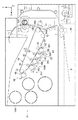
図1は、本発明の実施形態に係る定着装置を有する画像形成装置の構成の一例を示している。画像形成装置10の装置本体10Aの上下方向を矢印Y方向、左右方向を矢印X方向、奥行き方向を矢印Z方向として記載する。
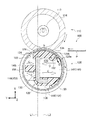
次に、定着装置100の詳細について説明する。
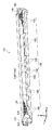
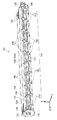
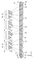
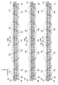
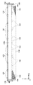
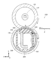
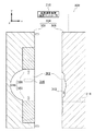
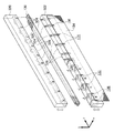
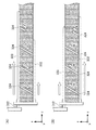
次に、インサート成形品である押付部材124の製造に用いられる金型装置300について図14〜図20を用いて説明する。金型装置300の上下方向を矢印y方向、左右方向を矢印x方向、奥行き方向を矢印z方向として記載する。
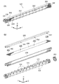
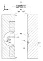
次に、インサート成形品である押付部材124の製造方法について図14〜図17、図21を用いて説明する。
14 中間転写体ベルト(被転写体の一例)
16 発光体ドラム(像保持体の一例)
18 帯電ローラ
20 LEDプリントヘッド(LPH)(露光装置の一例)
22 現像装置
24 現像ローラ
26 クリーニングブレード
28 画像形成ユニット
30 転写ローラ(転写装置の一例)
34 二次転写装置
100 定着装置
110 加熱ロール(ローラの一例)
112 ハロゲンランプ(熱源の一例)
114 ローラ部
120 加圧ローラ
122 無端状ベルト
124 押付部材
126 案内部
128 押付部
128a 内方面
128b 外方面
130 金属板(板材の一例)
132 突出部
134 シート部材
136 貫通孔
138 長尺部
140 第1のリブ群(複数のリブの一例)
142 第2のリブ群
144 第3のリブ群
146 サイド部
148 張出部
150 不織布
152 リブ
154 連結部
156 逃げ溝
158 熱収縮部
160 リブ
162 係止部
164 リブ
166 露出部分
300 金型装置
302 キャビティ
304 金型
306 固定側金型
308 可動側金型
310 加熱装置
312 注入口
314 吸引口
316 位置決め溝
318 挟持部材
320 下部可動コア
320 上部可動コア
322 下部可動コア
324 リブ用溝
326 連結部用溝
328 挟持部
330 押付部相当部
332 長尺部相当部
Claims (4)
- 長尺なキャビティを有する金型と、
長手方向を前記キャビティの長手方向に向けられて前記キャビティに入れられた長尺な金属板を、前記キャビティの横断面から見た場合において、前記キャビティの中心からオフセットした位置で挟持する挟持部材と、
前記キャビティに樹脂材を注入するための注入口と、
を有し、
前記金属板を前記挟持部材によって挟持した状態で前記注入口より前記キャビティに樹脂材を注入したときに前記金属板の両側に注入される樹脂材の量が均等となるように、前記金型および前記挟持部材の形状が決定されている金型装置。 - 前記挟持部材は、前記キャビティの長手方向において間を隔てて設けられる複数の挟持部を有し、
前記キャビティには、可撓性を有するシート部材が前記複数の挟持部に渡って配置されるように入れられ、
前記注入口は、前記キャビティに注入される前記樹脂材によって前記シート部材が前記複数の挟持部に押し付けられるように、前記キャビティの横断面から見た場合において、前記シート部材に対して前記複数の挟持部とは反対側に設けられている請求項1に記載の金型装置。 - 前記挟持部材は、前記金属板の厚みを縮小させつつ前記金属板を挟持する請求項1または請求項2に記載の金型装置。
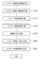
- 請求項1に記載の金型装置の前記キャビティに前記金属板を入れ、前記挟持部材によって前記金属板を挟持する挟持工程と、
前記金属板が前記金型および前記挟持部材と同温度となるように、前記金属板を加熱する金属板加熱工程と、
前記注入口から前記樹脂材を前記金属板が入れられたキャビティに注入する注入工程と、
前記樹脂材を冷却し、前記金属板と前記樹脂材をインサート成形品として一体化する一体化工程と、
前記インサート成形品を前記キャビティから取り出す取出工程と、
を有するインサート成形品の製造方法。
Priority Applications (3)
| Application Number | Priority Date | Filing Date | Title |
|---|---|---|---|
| JP2011068765A JP5772131B2 (ja) | 2011-03-25 | 2011-03-25 | 金型装置およびインサート成形品の製造方法 |
| US13/214,750 US8944797B2 (en) | 2011-03-25 | 2011-08-22 | Molding apparatus and method for manufacturing insert molded article |
| CN201110353091.3A CN102692853B (zh) | 2011-03-25 | 2011-11-09 | 用于制造插入模制件的模制装置和方法 |
Applications Claiming Priority (1)
| Application Number | Priority Date | Filing Date | Title |
|---|---|---|---|
| JP2011068765A JP5772131B2 (ja) | 2011-03-25 | 2011-03-25 | 金型装置およびインサート成形品の製造方法 |
Publications (2)
| Publication Number | Publication Date |
|---|---|
| JP2012201030A true JP2012201030A (ja) | 2012-10-22 |
| JP5772131B2 JP5772131B2 (ja) | 2015-09-02 |
Family
ID=46858404
Family Applications (1)
| Application Number | Title | Priority Date | Filing Date |
|---|---|---|---|
| JP2011068765A Expired - Fee Related JP5772131B2 (ja) | 2011-03-25 | 2011-03-25 | 金型装置およびインサート成形品の製造方法 |
Country Status (3)
| Country | Link |
|---|---|
| US (1) | US8944797B2 (ja) |
| JP (1) | JP5772131B2 (ja) |
| CN (1) | CN102692853B (ja) |
Families Citing this family (1)
| Publication number | Priority date | Publication date | Assignee | Title |
|---|---|---|---|---|
| JP6544993B2 (ja) * | 2014-06-23 | 2019-07-17 | キヤノン株式会社 | 定着用部材の製造装置 |
Citations (2)
| Publication number | Priority date | Publication date | Assignee | Title |
|---|---|---|---|---|
| JPS5828314A (ja) * | 1981-07-15 | 1983-02-19 | Hitachi Ltd | 金属板と樹脂の複合成形品 |
| JP2005249992A (ja) * | 2004-03-03 | 2005-09-15 | Fuji Xerox Co Ltd | 定着装置および画像形成装置 |
Family Cites Families (10)
| Publication number | Priority date | Publication date | Assignee | Title |
|---|---|---|---|---|
| JPH04328838A (ja) | 1991-04-30 | 1992-11-17 | Hitachi Cable Ltd | 回路基板の製造方法 |
| JP3119002B2 (ja) | 1992-11-13 | 2000-12-18 | キヤノン株式会社 | 加熱装置 |
| JP3524265B2 (ja) | 1996-04-26 | 2004-05-10 | キヤノン株式会社 | 加熱装置 |
| JP3723522B2 (ja) * | 2001-08-03 | 2005-12-07 | 富士通株式会社 | 金属成形体製造方法 |
| TWI327756B (en) * | 2002-11-29 | 2010-07-21 | Apic Yamada Corp | Resin molding machine |
| US7497679B2 (en) * | 2004-06-21 | 2009-03-03 | Mamada Sangyo | Injection mold having a switching valve |
| JP2006133294A (ja) | 2004-11-02 | 2006-05-25 | Canon Inc | 加熱装置 |
| JP2008064924A (ja) | 2006-09-06 | 2008-03-21 | Seiko Epson Corp | 定着装置及び画像形成装置 |
| JP5776256B2 (ja) * | 2011-03-25 | 2015-09-09 | 富士ゼロックス株式会社 | 定着装置および画像形成装置 |
| JP5776257B2 (ja) * | 2011-03-25 | 2015-09-09 | 富士ゼロックス株式会社 | 定着装置および画像形成装置 |
-
2011
- 2011-03-25 JP JP2011068765A patent/JP5772131B2/ja not_active Expired - Fee Related
- 2011-08-22 US US13/214,750 patent/US8944797B2/en active Active
- 2011-11-09 CN CN201110353091.3A patent/CN102692853B/zh not_active Expired - Fee Related
Patent Citations (2)
| Publication number | Priority date | Publication date | Assignee | Title |
|---|---|---|---|---|
| JPS5828314A (ja) * | 1981-07-15 | 1983-02-19 | Hitachi Ltd | 金属板と樹脂の複合成形品 |
| JP2005249992A (ja) * | 2004-03-03 | 2005-09-15 | Fuji Xerox Co Ltd | 定着装置および画像形成装置 |
Also Published As
| Publication number | Publication date |
|---|---|
| JP5772131B2 (ja) | 2015-09-02 |
| CN102692853A (zh) | 2012-09-26 |
| US20120242001A1 (en) | 2012-09-27 |
| US8944797B2 (en) | 2015-02-03 |
| CN102692853B (zh) | 2016-01-13 |
Similar Documents
| Publication | Publication Date | Title |
|---|---|---|
| JP5669010B2 (ja) | 定着装置及びその定着装置を備えた画像形成装置 | |
| JP5776256B2 (ja) | 定着装置および画像形成装置 | |
| EP2177955B1 (en) | Fixing Device and Image Forming Apparatus with Heating Member Heated Uniformly in Circumferential Direction | |
| US7945198B2 (en) | Fixing device and image forming apparatus comprising same | |
| US8781379B2 (en) | Fusing device, print device and apparatus for heating belt | |
| JP5776257B2 (ja) | 定着装置および画像形成装置 | |
| JP6111657B2 (ja) | 定着装置及び画像形成装置 | |
| JP2014186211A (ja) | 定着装置及び画像形成装置 | |
| JP6108730B2 (ja) | 定着装置 | |
| JP2012252338A (ja) | 定着装置及び画像形成装置 | |
| JP6350137B2 (ja) | 定着装置及び画像形成装置 | |
| JP2014048624A5 (ja) | ||
| JP2017173774A (ja) | 冷却装置及び画像形成装置 | |
| US8331840B2 (en) | Fixing device and image forming apparatus using interdigitated rollers | |
| JP2015011142A (ja) | 定着装置及び画像形成装置 | |
| JP5772131B2 (ja) | 金型装置およびインサート成形品の製造方法 | |
| JP5289175B2 (ja) | 像加熱装置 | |
| JP6665526B2 (ja) | 定着装置及び画像形成装置 | |
| US20150110529A1 (en) | Fuser for uniforming temperature of heating device | |
| JP6638469B2 (ja) | ガイド部材の製造方法、端部ガイド部材の製造方法および定着装置 | |
| JP2021148956A (ja) | 加熱装置、定着装置および画像形成装置 | |
| JP5645037B2 (ja) | 定着装置および画像形成装置 | |
| JP2005250298A (ja) | 定着装置及び画像形成装置 | |
| JP6071351B2 (ja) | 画像加熱装置 | |
| JP2014174536A (ja) | 定着装置及び画像形成装置 |
Legal Events
| Date | Code | Title | Description |
|---|---|---|---|
| A621 | Written request for application examination |
Free format text: JAPANESE INTERMEDIATE CODE: A621 Effective date: 20140218 |
|
| A977 | Report on retrieval |
Free format text: JAPANESE INTERMEDIATE CODE: A971007 Effective date: 20150116 |
|
| A131 | Notification of reasons for refusal |
Free format text: JAPANESE INTERMEDIATE CODE: A131 Effective date: 20150127 |
|
| A521 | Written amendment |
Free format text: JAPANESE INTERMEDIATE CODE: A523 Effective date: 20150212 |
|
| TRDD | Decision of grant or rejection written | ||
| A01 | Written decision to grant a patent or to grant a registration (utility model) |
Free format text: JAPANESE INTERMEDIATE CODE: A01 Effective date: 20150602 |
|
| A61 | First payment of annual fees (during grant procedure) |
Free format text: JAPANESE INTERMEDIATE CODE: A61 Effective date: 20150615 |
|
| R150 | Certificate of patent or registration of utility model |
Ref document number: 5772131 Country of ref document: JP Free format text: JAPANESE INTERMEDIATE CODE: R150 |
|
| LAPS | Cancellation because of no payment of annual fees |